Design of Dual Circularly Polarized Sequentially-Fed Patch Antennas for Satellite Applications
by
 , , and
Santi Concetto Pavone
1,2,*,† ,
,
Giorgio Sebastiano Mauro
3,4,† ,
,
Loreto Di Donato
1,2,† and
Gino Sorbello
1,2,†
1
Department of Electrical, Electronics, and Computer Engineering (DIEEI), Viale Andrea Doria 6, 95125 Catania, Italy
2
Consorzio Nazionale Interuniversitario per le Telecomunicazioni (CNIT), Viale G.P. Usberti, 181/A Pal. 3, 43124 Parma, Italy
3
National Institute for Nuclear Physics (INFN), National Southern Laboratories (LNS), Via S. Sofia 62, 95123 Catania, Italy
4
Department of Information Engineering, Infractructures, and Sustainable Energy, “Mediterranea” University of Reggio Calabria, Salita Melissari, 89124 Reggio Calabria, Italy
*
Author to whom correspondence should be addressed.
†
These authors contributed equally to this work.
Appl. Sci. 2020, 10(6), 2107; https://doi.org/10.3390/app10062107
Submission received: 22 January 2020
/
Revised: 9 March 2020
/
Accepted: 16 March 2020
/
Published: 20 March 2020
(This article belongs to the Collection Electromagnetic Antennas for HF, VHF, and UHF Band Applications)
Abstract
:In this paper, we present the design and fabrication of two dual circularly polarized (CP) patch antennas that can be profitably used as feeders for reflector systems normally adopted for satellite applications. In the first part of the manuscript, we propose the optimization of a dual-CP patch antenna, loaded by a fence of passive monopoles around it to increase antenna gain for high elevation angles. To achieve dual-CP operation mode, the circular patch has been sequentially-fed by three pins, whose mutual phase-shift is equal to . The antenna feeding network was placed on the antenna back and designed using microstrip technology. Two different input ports provide both right-hand (RH) and left-hand (LH) circular polarizations. A prototype of such an antenna was fabricated and measured at GHz. Furthermore, to test the versatility of the proposed single radiating patch, in the second part of the manuscript, we present the results of geometrically scaling at GHz (higher UHF band) and this was used as a building block for the design of a dual-CP sequentially-fed 2-by-2 array antenna. The results for both the proposed antennas are satisfactory in terms of impedance bandwidth, broad radiation pattern, gain and cross-polarization rejection, thus they can be profitably used as feeders for reflectors at relatively low frequencies.
1. Introduction
Among various kinds of antennas radiating non-directive beams, patches can be undoubtedly considered widely-adopted low-cost and low-profile solutions. Indeed, patch antennas can be easily fabricated by using the standard and commonly-used microstrip technology. In such a way, different single patch shapes, as well as patch arrangements in arrays, can be easily fabricated on the same substrate without increasing the whole circuit fabrication complexity, depending on target application.
Circularly polarized (CP) antennas [1,2,3,4] at relatively low frequencies (higher UHF band) have been profitably adopted in several satellite applications such as CubeSats [5,6], MEO satellites [7], telemetry tracking and command (TTC) antennas [8], near-field focusing [9,10,11] only to mention a few. In particular, CP patch antennas combine the advantages of fabrication easiness and of CP: the antenna does not need to be oriented along a particular direction, it is insensible to Faraday rotation, and the channel capacity is inherently duplicated by using the two orthogonal circular polarizations. Such requirements are of primary importance especially for satellite or RADAR [12,13] applications, in which the effects of ionosphere and rain have to be carefully taken into account in antenna design.
However, two important drawbacks of single-feed patch antennas are their reduced axial ratio (AR) bandwidth and their poor polarization purity. To mitigate such effects, it is sometimes useful to exploit sequentially-rotated multi-feed patch antennas, as outlined in [14,15].
To deal with these issues, in the first part of the paper we propose the design and fabrication of a sequentially-fed [15,16] circular patch antenna with relative phases of , and and operating at GHz. The antenna radiates dual-CP by connecting alternatively the two input ports of the microstrip feeding network printed on the antenna back. Useful and comprehensive techniques to design both antenna arrays and feeding networks in microstrip technology can be found in [17]. Thanks to their inherent compactness, microstrip feeding networks have been adopted both for applications at relatively low frequencies, i.e., in UHF band [18] and also in the range of microwaves [19].
Moreover, to increase antenna compactness and to allow more flexibility in aperture distribution shaping, in the second part, the sequentially-fed patch antenna was properly scaled and adopted as building block for the design of a 2-by-2 array for applications in the higher UHF band, at the operating frequency of GHz. The array configuration increases antenna gain and can be also used to synthesize the difference (delta, ) radiation pattern normally used to track satellites from ground stations. It is worth noting that a set of properly designed passive monopoles has been included in the antenna design to compensate unavoidable gain loss for large elevation angles. Indeed, passive monopoles are usually adopted to compensate antenna gain loss and to preserve also CP purity at high elevation angles () [20].
The resulting low axial ratio (AR) and the symmetric broad radiation pattern allow the antennas to be profitably used as a reflector primary feeders for satellite applications.
The paper is organized as follows. In Section 2, the operating principles of a dual-CP polarized sequentially-fed patch antenna loaded by a fence of passive monopoles are discussed, considering the design and realization of a prototype operating at GHz. In Section 3, the proposed single radiating element is used as a building block for the design of a 2-by-2 array operating in the higher UHF band at GHz for satellite applications, and in Section 4 the proposed array is experimentally tested. Finally, conclusions are drawn.
2. Design and Characterization of a Dual-CP Sequentially-Fed Single Patch Antenna
In this Section, the design and fabrication of a dual-CP sequentially-fed patch antenna are presented, extending the results shown in [21] through the prototype fabrication and experimental characterization in an anechoic chamber.
Let us consider a circular metallic patch suspended in air to minimize losses due to the dielectric (Figure 1). It is fed in such a way to radiate a broad beam in the boresight direction () by exciting the fundamental mode, according to the cavity model in [22]. Such a circular patch is sequentially-fed by using three pins rotated of each other [15], in such a way to generate a CP with a considerable AR bandwidth.
The proper phase-shift was achieved by designing the feeding network in microstrip technology on the antenna back. With reference to Figure 2a, the microstrip line impedances and lengths were properly synthesized according to the systematic methods explained in [23,24,25,26,27,28], and for the sake of convenience are reported in Table 1. The substrate used to realize the feeding network was a ROGERS TMM4 of thickness mm, relative electrical permittivity and loss tangent . In such a network, the two input ports allow dual-CP operation mode, by simply alternatively feeding the two ports.
To increase the antenna gain close to the end-fire direction (), a fence of eight passive monopoles, connected to the antenna ground plane, was placed. This solution mitigates the unavoidable cross-polarization at high elevation angles [21], and is lightweight relative to cavity-backed antenna solutions [29].
The antenna geometry was parametrically studied by using the full-wave commercial software Ansys HFSS, by acting on its relevant parameters, whose optimized values are summarized for the sake of conciseness in Table 2. It is worth mentioning that the antenna was optimized by means of physical considerations and not by using blind multi-variable optimization algorithms. The dominant physical effects associated to most relevant geometrical parameters on final antenna radiation pattern. For instance, monopole heights were tuned from to to achieve satisfactory gain compensation at high elevation angles. Moreover, patch radius was chosen to set antenna central frequency, according to the general considerations in [22]. Finally, the patch height was also used for tuning purposes.
Furthermore, to verify the correctness of the design procedure, a prototype of sequentially-fed circular patch antenna was fabricated for operating over the bandwidth GHz, as shown in Figure 2b. The effect of passive monopoles on the radiated field pattern was investigated by simulating the resulting antenna both in presence and in absence of monopoles, as shown in Figure 3a,b, both in cut planes. As it is apparent, the monopoles have the positive effect of increasing antenna gain for elevation angles far from broadside direction ().
As it can be inferred from Figure 3c, simulated (empty triangular/squared markers, dashed lines) and also measured (filled triangular/squared markers, continuous lines) antenna impedance matching at the two input ports are satisfactory and almost constants ( dB in both cases) in all of the considered band. It has to be noticed that the degradation of measured reflection coefficient with respect to the ideal simulated one (with a commercial circuital software) is mainly due to fabrication tolerances and to the low-cost adopted technology. Moreover, the isolation between input RHCP and LHCP ports ( parameter) was simulated (empty circular markers, dashed line) and measured (filled circular markers, dashed line); they are satisfactory ( dB) and almost constant over all the considered bandwidth GHz.
The measured antenna co-polar and cross-polar gain patterns are shown in Figure 3d. Although the antenna radiates a broad pattern in the elevation plane, it exhibits a good cross-polarization rejection, also thanks to the monopole fence positive effect, that allows us to compensate the pattern gain reduction at high elevation angles typical of patch antennas.
3. Dual-CP 2-by-2 Array Antenna for Satcom Applications
Once we evaluated the radiation performances and the polarization purity of a single sequentially-fed patch antenna loaded by a fence of passive monopoles, the antenna was properly scaled to be used as a building block for the design of a dual-CP 2-by-2 array, operating in the higher UHF band at GHz. In this case, the antenna was loaded at its center and around it by passive monopoles to increase the antenna gain close to end-fire direction. In Figure 4a the array geometry is presented by highlighting the relevant parameters for antenna optimization. To enhance the antenna compactness, the circular patches composing the array were cut in correspondence of array symmetry axes, without significantly affecting the radiation pattern due to the two-folded symmetry preservation. In addition, the presence of four passive monopoles at the antenna center helps to compensate tip/edge effects due to the cuts. The final parameter list used to fabricate the antenna prototype is shown in Table 3.
Moreover, in Figure 4b, the simulated reflection coefficient (, ) versus frequency, obtained by alternatively feeding both RHCP and LHCP ports, is shown, thus demonstrating a good array impedance matching. Instead, in Figure 4c the antenna gain at is shown over all the considered bandwidth, clearly demonstrating a satisfactory gain for a feeder of reflectors in Satcom applications.
On the other hand, in Figure 4d, the simulated broadside AR versus frequency is presented in the bandwidth GHz, by considering both presence (traces with filled markers) and absence (traces with empty markers) of monopoles. As it is apparent, monopoles are able to greatly increase antenna polarization purity at high elevation angles (), since the simulated AR can be decreased up to 1 dB over almost all the operating bandwidth. Moreover, to highlight the effect of monopoles also on antenna gain elevation pattern, in Figure 5, the simulated RHCP () and LHCP () gain patterns versus elevation angle are shown, with (filled markers) and without (empty markers) monopoles around the 2-by-2 array, for the cut-planes at (a) and at (b) . As it is apparent, the presence of monopoles results in an increase of antenna gain for large elevation angles (), as well as in an enhancement of the polarization purity, since the cross-polar gain is remarkably reduced of 10 dB with respect to the case without monopoles.
The proposed array antenna was designed to be used as primary feeder of reflectors operating in S-band, because of this, the stability of phase center position versus frequency has to be verified in order to ensure efficient reflector illumination. For such kinds of arrays, in which geometric symmetries with respect to xz and yz planes, the phase center has to lie on the z-axis. If no phasing is imposed on the antenna aperture, the phase center is exactly on it, at the central frequency. When a frequency shift occurs, in general a linear phasing is present, hence the phase center moves a little bit on the z-axis. However, in our case the phase center displacement was almost negligible, since the operating bandwidth was not so large and the antenna size was smaller than the operating wavelength. In [30] further theoretical details can be found.
4. Array Prototype Fabrication and Measurements
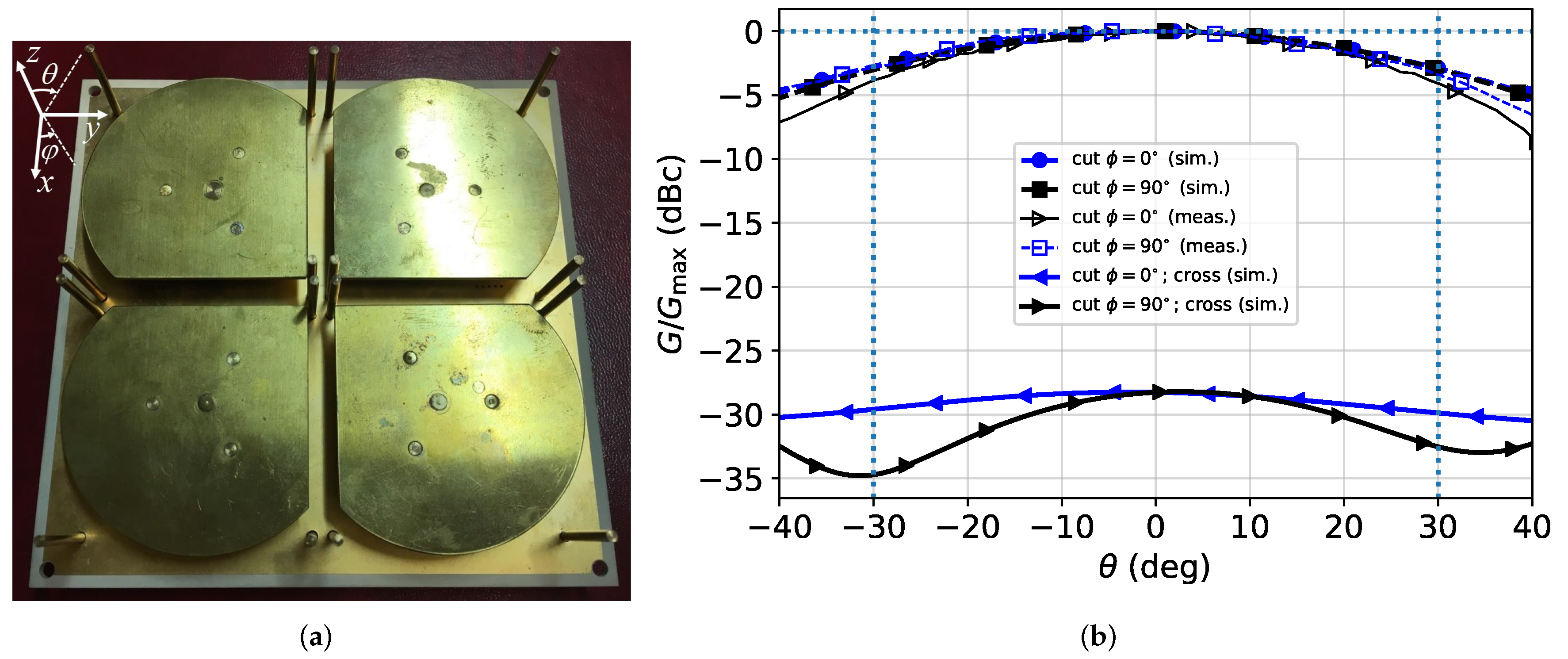
A prototype of the 2-by-2 array operating in the higher UHF band ( GHz) is shown in Figure 6a. The gain of such an antenna is reported in Figure 6b, in which a fair agreement between simulated and measured co-polar gain patterns can be found in the elevation angle range . Moreover, the array presents a very low cross-polar component (<−25 dB), as it can be inferred from the simulated traces with filled triangle markers.
It is worth noting that, to ensure the dual-CP antenna performances, the CP radiation pattern should be measured by feeding alternatively both RHCP and LHCP input ports. However, by considering that the radiated gain pattern does not differ significantly if the input port is switched, for the sake of brevity, in Figure 6b only the co-polar and cross-polar gain patterns radiated by the array are provided at the central frequency GHz, when the RHCP input port is fed. Such results allow the array to be used as a primary feeder for reflector systems for S-band satellite applications.
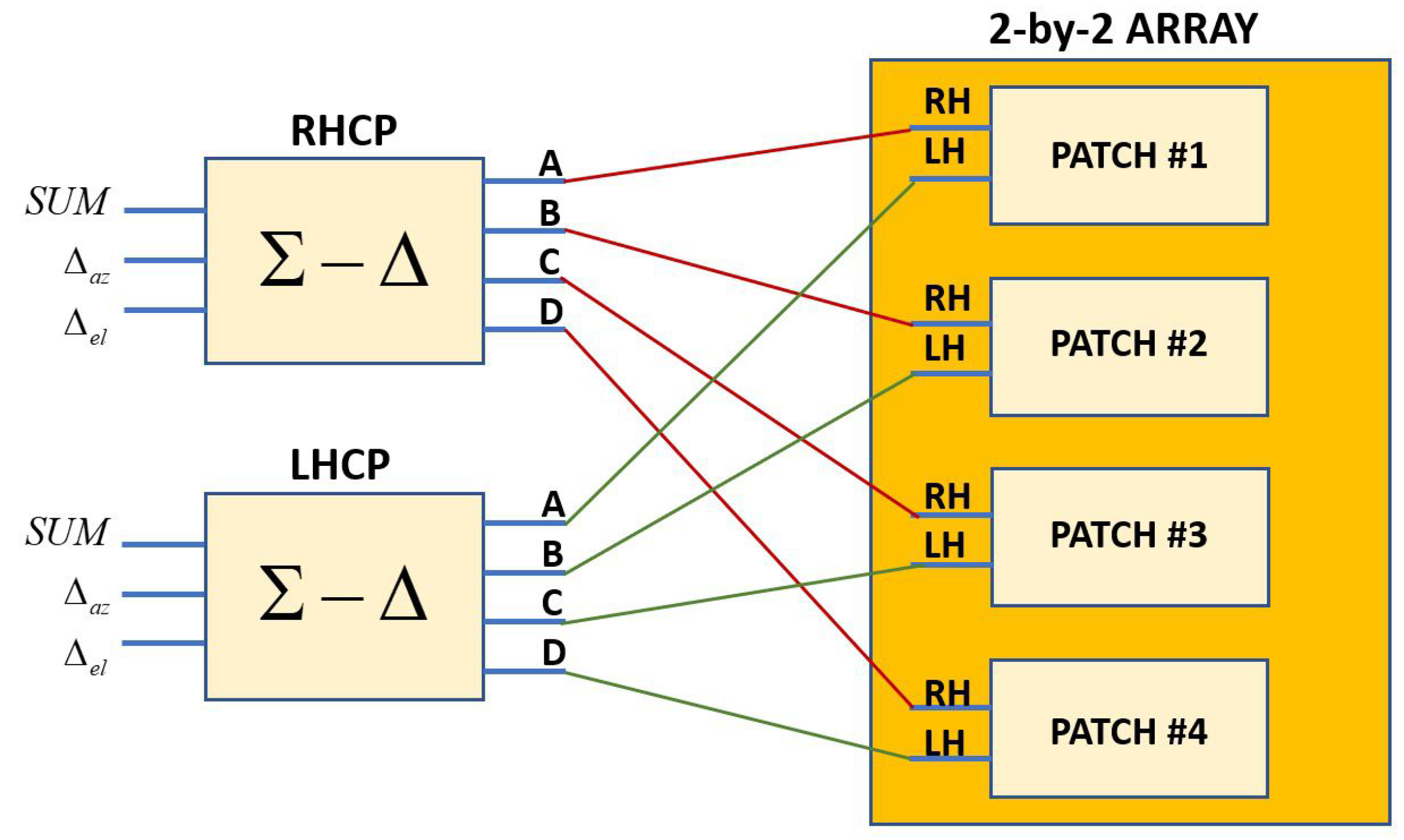
The feeding scheme that guarantees the proper phase shifts between the three pins used to feed array patches (already presented in Figure 2a), and thus CP, was scaled and replicated for each element of the array. Finally, the four RHCP (LHCP) ports were connected to two standard RHCP (LHCP) networks [31] to obtain the RHCP (LHCP) sum and difference patterns required for satellite tracking, as schematically shown in Figure 7. The two feeding networks were realized on a separate board in microstrip technology. On the other hand, the scaled networks used to feed each array element, schematically shown in Figure 2a, are printed on their back. The four feeding networks were fabricated by using a ROGERS TMM4 substrate, with different thickness mm, due to the frequency scaling at GHz.
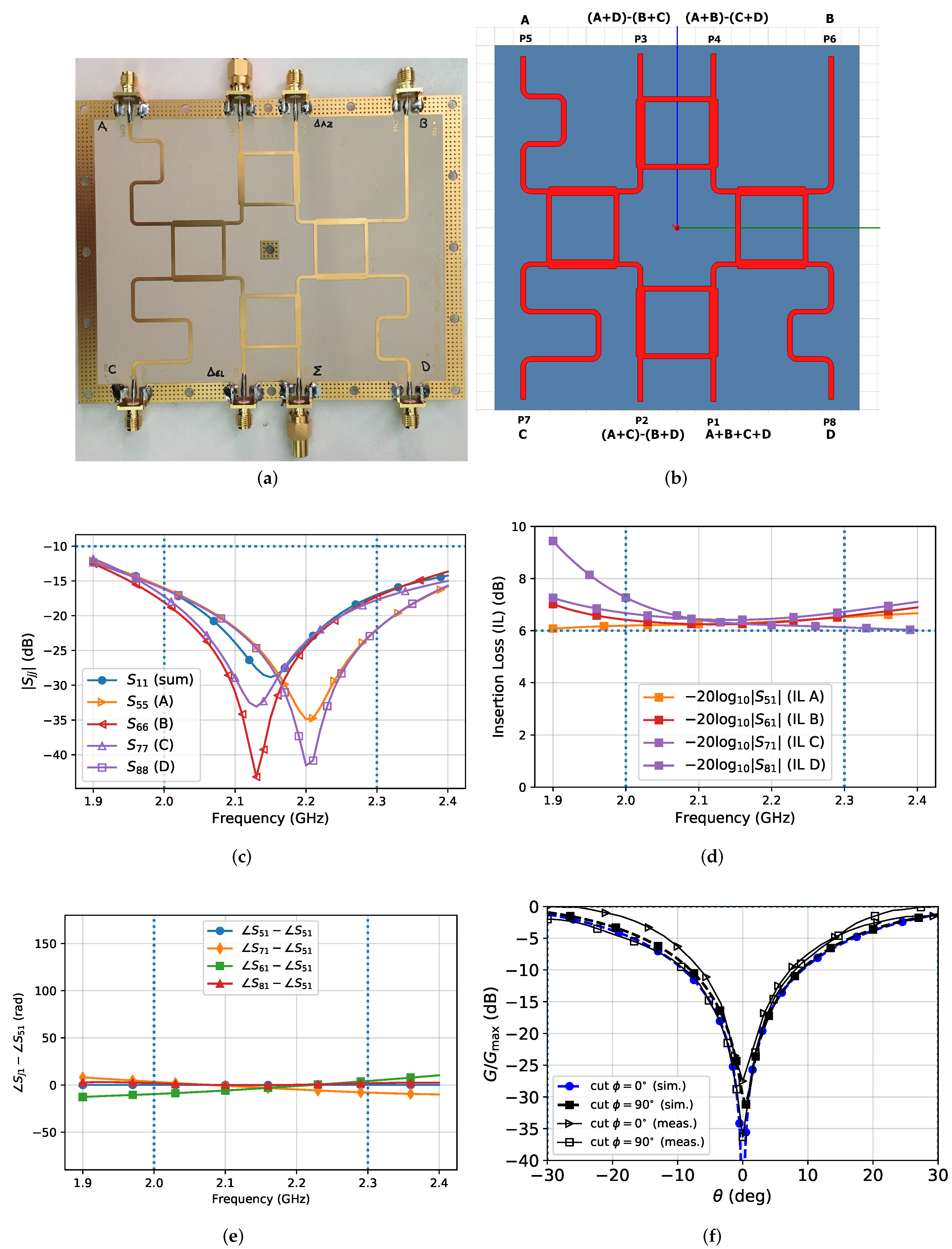
The feeding network was fabricated as shown in Figure 8a, whereas in Figure 8b the circuit layout is presented, in which all network ports are labeled from P1 to P8. According to [31], the network is able to synthesize the sum () and the difference (, ) patterns required for satellite azimuthal and elevation tracking. In particular, the RHCP (LHCP) networks were connected through the ports labeled by A, B, C and D to the four RHCP (LHCP) array input ports. The sum pattern (A+B+C+D signal) is obtained at port P1. The two difference patterns, i.e., and , are instead obtained by synthesizing the signals A+B-C-D and A+C-B-D at ports P4 and P2, respectively. Moreover, In Figure 8c the simulated reflection coefficients at network ports (), which are directly connected to the array RHCP/LHCP ports, are shown. For the sake of simplicity, in Figure 8d the simulated the insertion loss () between network output (A, B, C and D) and input (P1) ports is also presented. As it is apparent, good reflection coefficients and satisfactory insertion loss occur. In Figure 8e the simulated relative phases between network output (A, B, C and D) and input (P1) ports is also provided. Such a result clearly shows that all the output signals of networks, used to feed the 2-by-2 array (Figure 7), are in phase over all the considered bandwidth, as required. The phase shifts used to generate CP are then simply obtained by connecting the outputs of the two networks to the four scaled versions of patch feeding networks, already provided in Figure 2a. Finally, for the sake of completeness in Figure 8f a comparison of simulated and measured difference patterns is provided, that in this case shows a fair agreement.
5. Conclusions
In this paper, the design, fabrication and measurements of a dual-CP sequentially-fed circular patch antenna, loaded by a fence of passive monopoles, are proposed. The antenna radiates a broad pattern in both the azimuthal and elevation planes with a good cross-polarization rejection. To achieve dual-CP operation mode, the circular patch was sequentially-fed by three pins, whose mutual phase-shift is equal to , while the antenna feeding network was designed in microstrip technology. Moreover, the presented antenna was used as a building block for the design and fabrication of a 2-by-2 array for higher UHF band satellite applications, showing a fair agreement between simulations and measurements. The proposed antennas can be profitably adopted as primary feeds for reflector systems for Satcom application.
Author Contributions
G.S. defined the specific application requirements and selected the antenna topology. S.C.P., G.S. and L.D.D. addressed conceptualization and methodology for the study, development and analysis of circularly polarized antenna. G.S.M. carried out the antenna optimization and experimental characterizations. Writing—original draft preparation, S.C.P.; writing—review and editing, S.C.P., L.D.D. and G.S. The research was carried out in the framework of an ongoing collaboration between the University of Catania and Sicilsat Communications S.r.l, for the development of compact, low cost, circularly polarized antennas for Satcom applications. All authors have read and agreed to the published version of the manuscript.
Funding
This research received no external funding.
Acknowledgments
This work has been supported by the PON Research and Innovation project AIM (Attraction and Mobility of Researchers), Action I.2, granted by the FSE European Union program. The authors would like to thank Concetto Squadrito and Giuseppe Distefano from Sicilsat Communications S.r.l., for antenna pattern measurements in anechoic chamber.
Conflicts of Interest
The authors declare no conflict of interest.
References
- Di Carlo, C.; Di Donato, L.; Mauro, G.; La Rosa, R.; Livreri, P.; Sorbello, G. A circularly polarized wideband high gain patch antenna for wireless power transfer. Microw. Opt. Technol. Lett. 2018, 60, 620–625. [Google Scholar] [CrossRef]
- Pavone, S.C.; Casaletti, M.; Albani, M. Automatic Design of a CP Fan-Beam Linear Slotted Array in SIW Technology. IEEE Access 2019, 7, 155977–155985. [Google Scholar] [CrossRef]
- Liao, S.; Xue, Q. Compact UHF Three-Element Sequential Rotation Array Antenna for Satcom Applications. IEEE Trans. Antennas Propag. 2017, 65, 2328–2338. [Google Scholar] [CrossRef]
- Zaid, J.; Abdulhadi, A.; Kesavan, A.; Belaizi, Y.; Denidni, T.A. Multiport Circular Polarized RFID-Tag Antenna for UHF Sensor Applications. Sensors 2017, 17, 1576. [Google Scholar] [CrossRef] [PubMed] [Green Version]
- Yasin, T.; Baktur, R. Circularly polarized meshed patch antenna for small satellite application. IEEE Antennas Wirel. Propag. Lett. 2013, 12, 1057–1060. [Google Scholar] [CrossRef]
- Nascetti, A.; Pittella, E.; Teofilatto, P.; Pisa, S. High-Gain S-band Patch Antenna System for Earth-Observation CubeSat Satellites. IEEE Antennas Wirel. Propag. Lett. 2015, 14, 434–437. [Google Scholar] [CrossRef]
- Falade, O.P.; Rehman, M.U.; Gao, Y.; Chen, X.; Parini, C.G. Single feed stacked patch circular polarized antenna for triple band GPS receivers. IEEE Trans. Antennas Propag. 2012, 60, 4479–4484. [Google Scholar] [CrossRef]
- Squadrito, P.; Livreri, P.; Di Donato, L.; Squadrito, C.; Sorbello, G. A Telemetry, Tracking, and Command Antennas System for Small-Satellite Applications. Electronics 2019, 8, 689. [Google Scholar] [CrossRef] [Green Version]
- Pavone, S.C.; Ettorre, M.; Casaletti, M.; Albani, M. Transverse circular-polarized Bessel beam generation by inward cylindrical aperture distribution. Opt. Expr. 2016, 24, 11103–11111. [Google Scholar] [CrossRef]
- Pavone, S.C.; Mazzinghi, A.; Freni, A.; Albani, M. Comparison between broadband Bessel beam launchers based on either Bessel or Hankel aperture distribution for millimeter wave short pulse generation. Opt. Express 2017, 25, 19548–19560. [Google Scholar] [CrossRef]
- Comite, D.; Fuscaldo, W.; Pavone, S.C.; Valerio, G.; Ettorre, M.; Albani, M.; Galli, A. Propagation of nondiffracting pulses carrying orbital angular momentum at microwave frequencies. Appl. Phys. Lett. 2017, 110, 114102. [Google Scholar] [CrossRef] [Green Version]
- Wissan, V.; Firmansyah, I.; Rizki Akbar, P.; Sri Sumantyo, J.T.; Kuze, H.; Yohandri, V. Development of circularly polarized array antenna for synthetic aperture radar sensor installed on UAV. Prog. Electromagn. Res. 2011, 19, 119–133. [Google Scholar]
- Pavone, S.C.; Martini, E.; Albani, M.; Maci, S.; Renard, C.; Chazelas, J. A novel approach to low profile scanning antenna design using reconfigurable Metasurfaces. In Proceedings of the 2014 International Radar Conference, Lille, France, 13–17 October 2014; pp. 1–4. [Google Scholar] [CrossRef]
- Teshirogi, T.; Tanaka, M.; Chujo, W. Wideband circularly polarised array antenna with sequential rotations and phase shifts of elements. In Proceedings of the Intern. Symp. Antennas Propag (ISAP 85), Kyoto, Japan, 7–9 October 1985. [Google Scholar]
- Hall, P.S.; Dahele, J.S.; James, J.R. Design principles of sequentially fed, wide bandwidth, circularly polarised microstrip antennas. IEE Proc. 1989, 136, 381–389. [Google Scholar] [CrossRef]
- Deng, C.; Li, Y.; Zhang, Z.; Feng, Z. A Wideband Sequential-Phase Fed Circularly Polarized Patch Array. IEEE Trans. Antennas Propag. 2014, 62, 3890–3893. [Google Scholar] [CrossRef]
- Garg, R.; Bhartia, P.; Bahl, I.J.; Ittipiboon, A. Microstrip Antenna Design Handbook; Artech House: Massachusetts, MA, USA, 2001. [Google Scholar]
- Chen, X.; Fu, G.; Gong, S.; Yan, Y.; Zhao, W. Circularly Polarized Stacked Annular-Ring Microstrip Antenna With Integrated Feeding Network for UHF RFID Readers. IEEE Antennas Wirel. Propag. Lett. 2010, 9, 542–545. [Google Scholar] [CrossRef]
- Wincza, K.; Gruszczynski, S. Microstrip Antenna Arrays Fed by a Series-Parallel Slot-Coupled Feeding Network. IEEE Antennas Wirel. Propag. Lett. 2011, 10, 991–994. [Google Scholar] [CrossRef]
- Harine, G.; Pavone, S.C.; Di Donato, L.; Di Mariano, P.; Distefano, G.; Livreri, P.; Prabagarane, N.; Squadrito, C.; Sorbello, G. Design of a Compact Dual Circular-Polarized Antenna for L-Band Satellite Applications. IEEE Antennas Wirel. Propag. Lett. 2020. [Google Scholar] [CrossRef]
- Mauro, G.S.; Torrisi, G.; Di Mariano, P.; Squadrito, C.; Emanuele, S.; Di Donato, L.; Sorbello, G. Wide Bandwidth Dual Port, Dual Sense Circular Polarization Antenna for Satellite Applications. In Proceedings of the ICEAA 2019, Granada, Spain, 9–13 September 2019. [Google Scholar]
- Balanis, C.A. Advanced Engineering Electromagnetics; John Wiley & Sons: New York, NY, USA, 2012. [Google Scholar]
- Wong, Y.S.; Zheng, S.Y.; Chan, W.S. Quasi-Arbitrary Phase-Difference Hybrid Coupler. IEEE Trans. Microw. Theory Tech. 2012, 60, 1530–1539. [Google Scholar] [CrossRef]
- Wu, Y.; Jiao, L.; Xue, Q.; Liu, Y. A Universal Approach for Designing an Unequal Branch-Line Coupler With Arbitrary Phase Differences and Input/Output Impedances. IEEE Trans. Compon. Packag. Manuf. Technol. 2017, 7, 944–955. [Google Scholar] [CrossRef]
- Park, M. Comments on “Quasi-arbitrary phase-difference hybrid coupler”. IEEE Trans. Microw. Theory Tech. 2013, 61, 1397–1398. [Google Scholar] [CrossRef]
- Wu, Y.; Shen, J.; Liu, Y. Comments on “Quasi-Arbitrary Phase-Difference Hybrid Coupler”. IEEE Trans. Microw. Theory Tech. 2013, 61, 1725–1727. [Google Scholar] [CrossRef]
- Ahn, H.; Tentzeris, M.M. Comments on “A Universal Approach for Designing an Unequal Branch-Line Coupler With Arbitrary Phase Differences and Input/Output Impedances”. IEEE Trans. Compon. Packag. Manuf. Technol. 2019, 9, 1208–1209. [Google Scholar] [CrossRef]
- Wu, Y.; Jiao, L.; Xue, Q.; Liu, Y. Reply to “Comments on ‘A Universal Approach for Designing an Unequal Branch-Line Coupler with Arbitrary Phase Differences and Input/Output Impedances’”. IEEE Trans. Compon. Packag. Manuf. Technol. 2019, 9, 1210–1216. [Google Scholar] [CrossRef]
- Tran, H.H.; Park, I. Wideband circularly polarized cavity-backed asymmetric crossed bowtie dipole antenna. IEEE Antennas Wirel. Propag. Lett. 2015, 15, 358–361. [Google Scholar] [CrossRef]
- Pavone, S.C.; Albani, M. Exact Formulas for the Determination of Antenna Local Phase Center. In Proceedings of the 2019 13th European Conference on Antennas and Propagation (EuCAP), Kraków, Poland, 31 March–4 April 2019; pp. 1–3. [Google Scholar]
- Gharibi, H.; Hojjat-Kashani, F. Design of a wideband monopulse antenna using four conical helix antennas. Prog. Electromagn. Res. 2012, 29, 25–33. [Google Scholar] [CrossRef] [Green Version]
Figure 1.
Side-view of the proposed sequential-fed patch antenna loaded by monopoles properly designed to increase the antenna gain close to end-fire direction, in which the relevant geometrical parameters are highlighted.
Figure 1.
Side-view of the proposed sequential-fed patch antenna loaded by monopoles properly designed to increase the antenna gain close to end-fire direction, in which the relevant geometrical parameters are highlighted.
Figure 2.
(a) Schematic of the feeding network in microstrip technology. By alternatively feeding the antenna at ports RHCP or LHCP, dual-CP operation mode is enabled. (b) Prototype of sequentially-fed patch antenna surrounded by a fence of passive monopoles and operating at GHz.
Figure 2.
(a) Schematic of the feeding network in microstrip technology. By alternatively feeding the antenna at ports RHCP or LHCP, dual-CP operation mode is enabled. (b) Prototype of sequentially-fed patch antenna surrounded by a fence of passive monopoles and operating at GHz.

Figure 3.
Simulated RHCP (GR) and LHCP (GL) gain patterns versus elevation angle with (filled markers) and without (empty markers) monopoles around the single radiating patch, for the cut-planes at (a) ϕ = 0° and at (b) ϕ = 90°. The results are provided at the central frequency f = 2.2 GHz. (c) Simulated (empty triangular/squared markers, dashed lines) and measured (filled triangular/squared markers, continuous lines) reflection coefficients at RHCP (SRHCP) and LHCP (SLHCP) input ports, together with simulated (empty circular markers, dashed line) and measured (filled circular markers, continuous line) isolation between RHCP and LHCP ports (SISOL), in the considered bandwidth [8.1,8.4] GHz. (d) Measured co-polar and cross-polar gain patterns at ϕ = 0° versus elevation angle at the operating frequency f = 8.25 GHz.


Figure 4.
(a) Side-view of the proposed 2-by-2 patch array operating in the higher UHF band. (b) Reflection coefficient (,) versus frequency over the operating bandwidth. (c) Gain versus frequency over the operating bandwidth. (d) Simulated broadside axial ratio () versus frequency, for different elevation and azimuthal angles. As it is apparent, the monopoles are able to increase significantly antenna polarization purity.

Figure 5.
Simulated RHCP () and LHCP () gain patterns versus elevation angle with (filled markers) and without (empty markers) monopoles around the 2-by-2 array, for the cut-planes at (a) and at (b) . The results are provided at the central frequency GHz.
Figure 5.
Simulated RHCP () and LHCP () gain patterns versus elevation angle with (filled markers) and without (empty markers) monopoles around the 2-by-2 array, for the cut-planes at (a) and at (b) . The results are provided at the central frequency GHz.
Figure 6.
(a) Prototype of dual-CP sequentially-fed 2-by-2 antenna array. (b) Simulated co-polar (thin continuous black line with empty triangles for the cut plane at , thin blue dashed line with empty squares for the cut plane at ) and measured co-polar (thin continuous black line with empty triangles for the cut plane at , thin blue dashed line with empty squares for the cut plane at ) and simulated cross-polar (thick blue and black continuous lines with filled triangles for the cut planes at and , respectively) gains of the array antenna at the central frequency GHz.

Figure 7.
Block scheme of the connections between networks and the 2-by-2 array RH/LH CP ports.

Figure 8.
(a) Fabricated network. (b) Layout. (c) Reflection coefficient () over all the considered bandwidth (d) Insertion Loss. (e) Relative phase. (f) Comparison of simulated (filled markers) and measured (empty markers) normalized difference patterns required for satellite tracking. Such patterns are obtained by connecting the antenna array to a standard network.


Table 1.
Dual-circularly polarized (CP) single patch feeding network parameters.
| Microstrip Line | Impedance [] | Length [mm] |
|---|---|---|
Table 2.
Single patch antenna geometric parameters ().
| Parameter | Description | Value [mm] | Value [] |
|---|---|---|---|
| Antenna radius | |||
| Patch radius | |||
| Monopole position | 11 | ||
| Monopole diameter | |||
| Substrate thickness | |||
| Monopole heights | |||
| Patch height |
Table 3.
The 2-by-2 array geometric parameters ().
| Parameter | Description | Value [mm] | Value [] |
|---|---|---|---|
| Dielectric thickness | |||
| Air gap thickness | 9 | ||
| Patch radius | 29 | ||
| Monopole radius | 1 | ||
| Monopole heights | 24 | ||
| Patch cut length | 41 | ||
| Adjacent monopole distance | 4 |
© 2020 by the authors. Licensee MDPI, Basel, Switzerland. This article is an open access article distributed under the terms and conditions of the Creative Commons Attribution (CC BY) license (http://creativecommons.org/licenses/by/4.0/).
Share and Cite
MDPI and ACS Style
Pavone, S.C.; Mauro, G.S.; Donato, L.D.; Sorbello, G. Design of Dual Circularly Polarized Sequentially-Fed Patch Antennas for Satellite Applications. Appl. Sci. 2020, 10, 2107. https://doi.org/10.3390/app10062107
AMA Style
Pavone SC, Mauro GS, Donato LD, Sorbello G. Design of Dual Circularly Polarized Sequentially-Fed Patch Antennas for Satellite Applications. Applied Sciences. 2020; 10(6):2107. https://doi.org/10.3390/app10062107
Chicago/Turabian StylePavone, Santi Concetto, Giorgio Sebastiano Mauro, Loreto Di Donato, and Gino Sorbello. 2020. "Design of Dual Circularly Polarized Sequentially-Fed Patch Antennas for Satellite Applications" Applied Sciences 10, no. 6: 2107. https://doi.org/10.3390/app10062107
Note that from the first issue of 2016, this journal uses article numbers instead of page numbers. See further details here.