Design and Performance Analysis of a Supercritical Carbon Dioxide Heat Exchanger


1
Korea Atomic Energy Research Institute 989-111, Daedeok-daero, Yuseong-gu, Daejeon 34057, Korea
2
National Funsion Research Institute 169-148 Gwahak-ro, Yuseong-gu Daejeon 34133, Korea
*
Author to whom correspondence should be addressed.
Appl. Sci. 2020, 10(13), 4545; https://doi.org/10.3390/app10134545
Submission received: 29 May 2020
/
Revised: 23 June 2020
/
Accepted: 23 June 2020
/
Published: 30 June 2020
(This article belongs to the Special Issue Recent Advancement of Thermal Fluid Engineering in the Supercritical CO2 Power Cycle)
Abstract
:This paper presents a preliminary design and performance analysis of a supercritical CO2 (SCO2) heat exchanger for an SCO2 power generation system. The purpose of designing a SCO2 heat exchanger is to provide a high-temperature and high-pressure heat exchange core technology for advanced SCO2 power generation systems. The target outlet temperature and pressure for the SCO2 heat exchanger were 600 °C and 200 bar, respectively. A tubular type with a staggered tube bundle was selected as the SCO2 heat exchanger, and liquefied petroleum gas (LPG) and air were selected as heat sources. The design of the heat exchanger was based on the material selection and available tube specification. Preliminary performance evaluation of the SCO2 heat exchanger was conducted using an in-house code, and three-dimensional flow and thermal stress analysis were performed to verify the tube’s integrity. The simulation results showed that the tubular type heat exchanger can endure high-temperature and high-pressure conditions under an SCO2 environment.
1. Introduction
The supercritical carbon dioxide (SCO2) Brayton cycle has been considered one of the most promising alternatives to existing power generation systems, such as the steam Rankine and gas Brayton cycles. The steam Rankine cycle can achieve high thermal efficiency due to the low pumping power, but the overall size of the system is large because the steam density of the low pressure side is lower than the atmospheric pressure. The turbine inlet temperature (TIT) of the gas Brayton cycle is higher than in the steam Rankine cycle. It can achieve a high thermal power output, but material integrity and high compression work problems still remain. The SCO2 cycle has the advantages of both the steam Rankine and gas Brayton cycles because of its fluid characteristics. First of all, the supercritical region of the SCO2 is readily accessible (Tc = 31.1 °C, Pc = 73.8 bar); thus, the system can be controlled easily compared to other critical state fluids. Because the SCO2 cycle operates near the critical point, the fluid reflects both liquid and gas properties. The compression work of the SCO2 consumes less than the conventional gas Brayton cycle. In addition, the density difference between the hot and cold sides are small. This means that the overall size of the SCO2 power generation system can be minimized compared to the conventional power generation systems. Based on the advantages, the SCO2 cycle can be applied to various technologies, such as concentrating power, fossil fuel, geothermal, nuclear, ship-board propulsion, waste heat recovery, etc. Therefore, the development of the SCO2 power cycle has been extensively studied.
Studies on the SCO2 cycle have taken place since the 1960s, but its development did not occur due to these technological advances [1,2]. In the 2000s, Dostal et al. [3] studied the SCO2 cycle as the next power generation system for Generation IV nuclear reactors because the TIT for advanced nuclear reactors is about 550 °C, a system operating condition which is between the steam Rankine and gas Brayton cycles. Because the SCO2 cycle can be designed in a wide range of the TIT, the SCO2 system has received more attention as the next power generation system. In addition, the SCO2 cycle can also be used in various heat sources, such as fossil fuel, concentrating solar power, shipboard propulsion, waste heat recovery, and geothermal.
After validating the SCO2 cycle as a new power generation system, numerous studies have been conducted to verify the cycle. Sandia National Laboratories designed a recompression configuration, and various experimental facilities have been developed, such as turbine and compressor performance characterizations [4,5,6]. The Naval Nuclear Laboratory designed and built an integrated system test (IST) for the SCO2 Brayton cycle. The IST is a simple recuperated Brayton cycle for variable turbomachinery tests. The system demonstrated that the SCO2 Brayton cycle was controlled throughout the entire system operation, but inherent problems related to the SCO2 Brayton cycle were identified [7,8,9]. Ecogen Power Systems designed a SCO2 power cycle (EPS-100) for exhaust heat recovery applications. The EPS-100 is the first commercial-scale SCO2 system, and it has a 7MWe scale with multiple stages of recuperation and extraction from the heat source. The validation test of the EPS-100 was completed, and commercialization took place [10,11]. The SunShot program, which develops the SCO2 Brayton cycle for a concentrating solar power (CSP) system, was initiated with a simple recuperated cycle [12]. The target demonstration of the SCO2 system is 10 MWe with a 50% net thermal efficiency.
To demonstrate the major components in the SCO2 power generation system, the SCO2’s heat exchanger and turbo-expander have been tested in a 1 MWe test loop [13,14]. A tubular-type heat exchanger was selected as the primary heater, which was connected with a commercial natural gas-fired combustor [13]. The SunShot program is the first MW-scale SCO2 power cycle demonstration in which the TIT is higher than 700 °C. A demonstration of the SCO2 power cycle was performed by considering the unique characteristics of the CSP system [14].
In addition, the US Department of Energy (DOE) designated SCO2 research as a cross-cutting technology and supercritical transformational electric power (STEP) program with a collaboration between fossil, nuclear, and renewable energy [15]. The program has focused on designing, constructing, commissioning, and operating a 10-MWe SCO2 pilot plant test facility. The detailed design of the facility and equipment is now proceeding. Fabrication and construction of a pilot test facility with a simple-cycle test will be finished at the end of 2020, and facility operation and testing with the recompression cycle is scheduled until 2022 [16,17].
In Korea, various kinds of experimental facilities have been developed and investigated for the SCO2 power cycle [18,19,20,21]. Recently, the development and testing of the SCO2 power cycle for a waste heat recovery system started in the Korea Atomic Energy Research Institute (KAERI). The target of the project is to develop a prototype SCO2 power generation system for a waste heat recovery system. The project aims at developing SCO2 core technology, such as turbomachinery and heat exchangers. A simple recuperated cycle was selected. The major components of the prototype are an SCO2 compressor and turbine, precooler, recuperator, and waste heat recovery heat exchanger. The target of the TIT is about 430 °C. To secure the TIT, it is important to manage the high-temperature and high-pressure heat exchange technologies under a SCO2 environment.
In this research, the SCO2 heat exchanger that will be used in the SCO2 power generation prototype is designed. The maximum target of the SCO2 outlet temperature and pressure is 200 bar and 600 °C, respectively. Based on the design conditions of the SCO2 heat exchanger, heat exchanger type selection, material selection, and tube specification based on the commercial availability were conducted. Preliminary performance analysis of the SCO2 heat exchanger was conducted using an in-house heat exchanger code, and the flow and thermal stress analysis of the SCO2 heat exchanger were performed using commercially available computational fluid dynamic (CFD) codes.
2. Design Considerations of Supercritical CO2 Heat Exchanger
2.1. Operating Condition of SCO2 Heat Exchanger
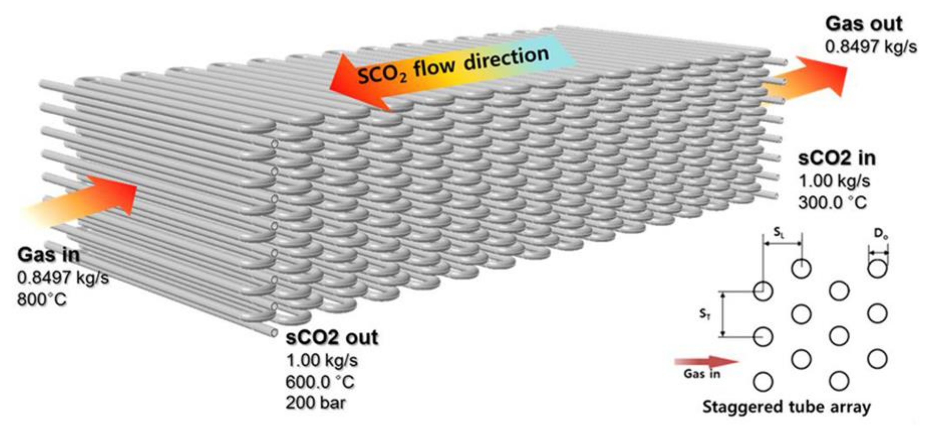
Table 1 lists the operating conditions of the SCO2 heat exchanger. The mass flow rate of the SCO2 is 1 kg/s, and the inlet and outlet temperatures of the SCO2 are 300 °C and 600 °C, respectively. The outlet pressure of the SCO2 is 200 bar. Based on the operating condition of the SCO2 power cycle, the pressure drop of the heat exchanger was limited to 1.5 bar. The heat duty of the SCO2 heat exchanger was 380kW. A combustion system was selected as a heat source for the SCO2. Flue gas is composed of liquefied petroleum gas (LPG) and air. The inlet temperature of the flue gas was set at 800 °C. The inlet temperature is based on the maximum allowable stress for the heat exchanger tube. The inlet mass flow rate of the flue gas was calculated as 0.8497 kg/s.
2.2. Heat Exchanger Type Selection
Heat exchanger types can be classified based on the number of working fluids, compactness, flow arrangements, and heat transfer mechanisms. Tubular, plate type, extended surface, and printed circuit heat exchanger types are typical heat exchangers used in industrial areas. Among the heat exchangers, the tubular heat exchanger is popular due to its flexibility: the core shape can be easily changed by the tube diameter, length, and arrangements. In addition, tubular heat exchangers are usually used in high-temperature and high-pressure conditions. A plate type heat exchanger consists of two flow membranes, and a number of plates are compressed or welded with a gasket. Therefore, it is not appropriate to use it in extreme operating conditions due to the possibility of leakage. Compared to the tubular and plate type heat exchangers, a higher effectiveness can be achieved by using extended surface heat exchangers. However, a high pressure drop can appear on extended surface heat exchangers. For compact size heat exchangers, printed circuit heat exchangers (PCHE) have been widely studied. The volume of a PCHE can be minimized up to 1/30 compared to conventional shell-and-tube heat exchangers with the same heat duty [22]. However, maintenance and inspection of a PCHE are difficult because these heat exchangers are manufactured by a diffusion bonding process. In addition, there are limitations in material selection for diffusion bonding processes.
The type of SCO2 heat exchanger can be determined by the desired operating condition. Because the target operating condition of the SCO2 heat exchanger is at a high temperature and high pressure (600 °C and 200 bar), the heat exchanger should endure high thermal stress and thermal shock. In addition, the maintenance and inspection of the heat exchanger should be easy. The tubular type heat exchanger has a low pressure drop and offers the least-risk design for the thermal shock resistance, and it has modest effectiveness. Because the flue gas was considered as the heat source, the pressure drop on the hot side should also be minimized. The flexible design of the tubular heat exchanger can offer a pressure drop on the flue gas side. Therefore, the tubular type was selected as the SCO2 heat exchanger.
2.3. Heat Exchanger Material Selection
Heat exchanger material selection is based on a combination of cost, moderate properties under the operating condition, fabricability, and availability. In addition, candidate materials are required to have good corrosion, oxidation, carburization, and brittleness resistance under the SCO2 condition. Because the operating condition of the SCO2 heat exchanger is at a high temperature and high pressure, it is important to determine an appropriate material that can endure extreme operating conditions. Based on the operating condition, the maximum material surface temperature was assumed to be 650 °C. The maximum allowable stress values were considered as criteria for the heat exchanger material selection [23]. According to the maximum allowable stress values for candidate materials in the SCO2 heat exchanger, S31042, S34709, and S34710 were selected because they have good corrosion and carburization resistance in SCO2 environments. Based on the experimental results of the corrosion and carburization resistance, experience at similar operating conditions, cost, and availability, S34709 was finally selected as the SCO2 heat exchanger material.
3. Design of Supercritical CO2 Heat Exchanger
Figure 1 illustrates a schematic of the SCO2 heat exchanger tube bundle. The tube specification was based on commercial availability and cost. The available tube diameter and the thickness of the S34709 material were 21.7 mm and 4.9 mm, respectively. The basic configuration of the SCO2 heat exchanger had a rectangular duct fed by a flue gas. The heat transfer from the hot flue gas to the cold SCO2 occurred in the rectangular duct. A staggered tube array with a counter-crossflow arrangement was considered. The tube length pitch (SL) and tube height pitch (ST) were 35 mm and 60 mm, respectively. The selection of the tube length pitch was based on the minimum thickness for pipe bends for induction and incrementing bending [24]. The straight line of the heat exchanger tube was 800 mm. The height and length of the tube were 471.7 mm and 2086.7 mm, respectively. Figure 2 shows the heat exchanger nozzle, header, and tube supporting structure. The total length of the SCO2 heat exchanger was estimated as 5132 mm, and the lengths of the SCO2 heat exchanger combustor and SCO2 heat exchanger chamber were 1577 mm and 2765 mm, respectively. As a concept for the tube-supporting structure, rectangular plates made by the welding method were considered.
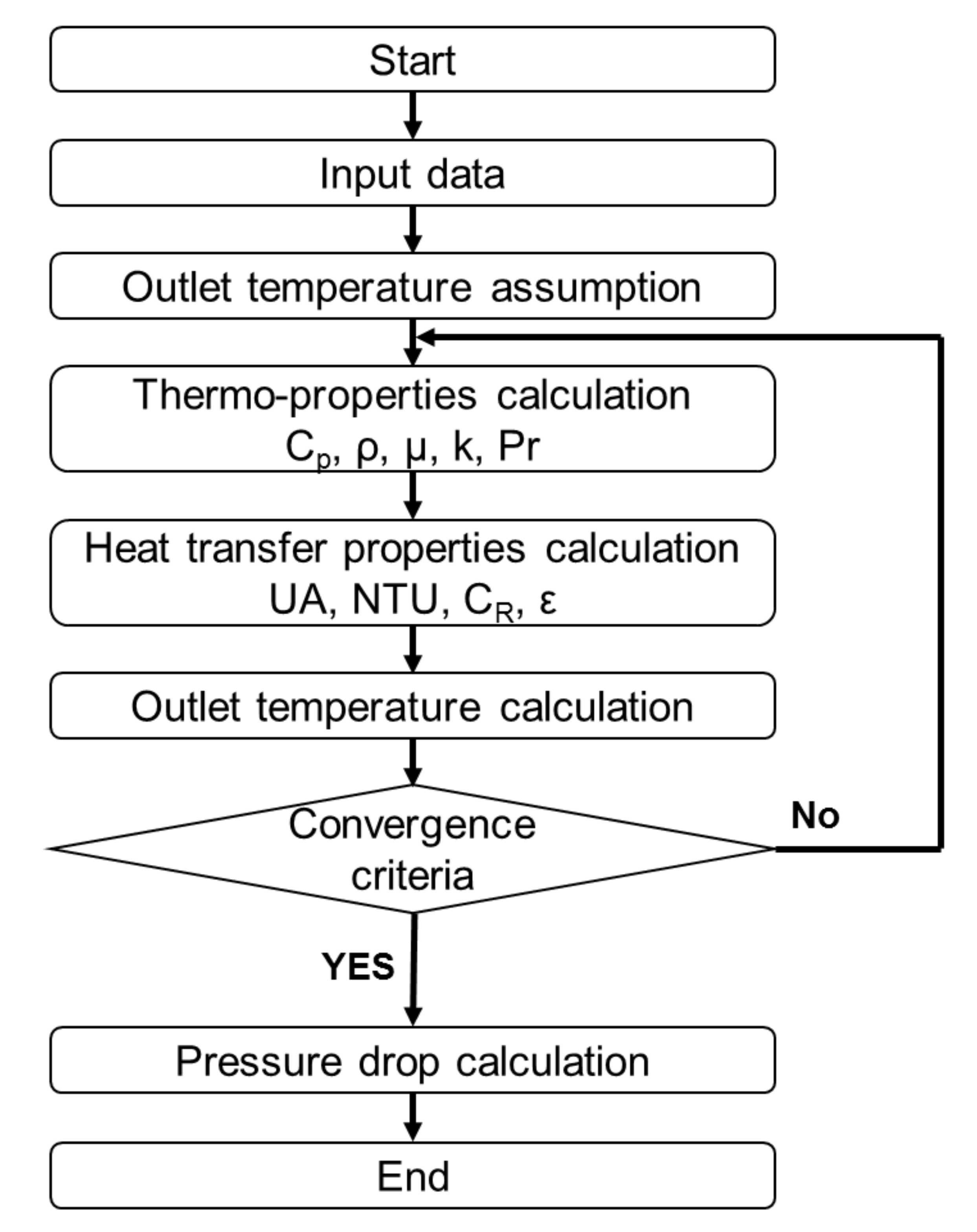
Preliminary simulation of the SCO2 heat exchanger was performed using an in-house heat exchanger analysis code. Figure 3 shows a program flow chart for the analysis of the SCO2 heat exchanger. An effective number of the transfer unit method was used for the simulation code. The thermo-properties of the flue gas and SCO2 were obtained from the NIST REFPROP Database 23, Version 9.1 [25]. The fluid properties, such as Reynolds number, heat transfer coefficient, and friction factor, were calculated based on the thermal properties of the working fluids. Then, the heat transfer characteristics, such as overall heat transfer coefficient, number of transfer units, and effectiveness, were computed to obtain the outlet temperature of the working fluid. The pressure drop of each fluid was then obtained when the calculation of the outlet temperature was converged. For the shell side, the heat transfer correlation proposed by Zukauskas [26] was used. The pressure drop correlation for the staggered tube banks was employed [27]. For the tube side, the heat transfer correlation proposed by Gnielinski [28] was used, and the pressure drop was calculated by considering the entrance, momentum, core friction, and exit effects [29]. The validation of the developed code was verified with other commercially available heat exchanger code. The simulation results showed that the outlet temperature (600.6 °C) can be obtained with the present design considerations of the SCO2 heat exchanger. In addition, the pressure drop on the SCO2 side satisfied the design constraints (<1.5 bar). However, there is a limitation in using the in-house heat exchanger code because it only represents the outlet conditions. This means that it is difficult to find local heat transfer characteristics along the heat exchanger tubes as well as thermal stress along the tubes. Therefore, the analysis of thermal characteristics was conducted using commercial three-dimensional CFD codes.
4. CFD Analysis of a Supercritical CO2 Heat Exchanger
Three-dimensional commercially available CFD codes were used to analyze the flow and thermal stress characteristics of the SCO2 heat exchanger. Flow and thermal stress analysis were performed. Based on the temperature and heat transfer coefficient distributions obtained from the flow analysis, thermal stress analysis was conducted to evaluate the tube’s integrity at the SCO2 heat exchanger operating condition.
4.1. Flow Analysis
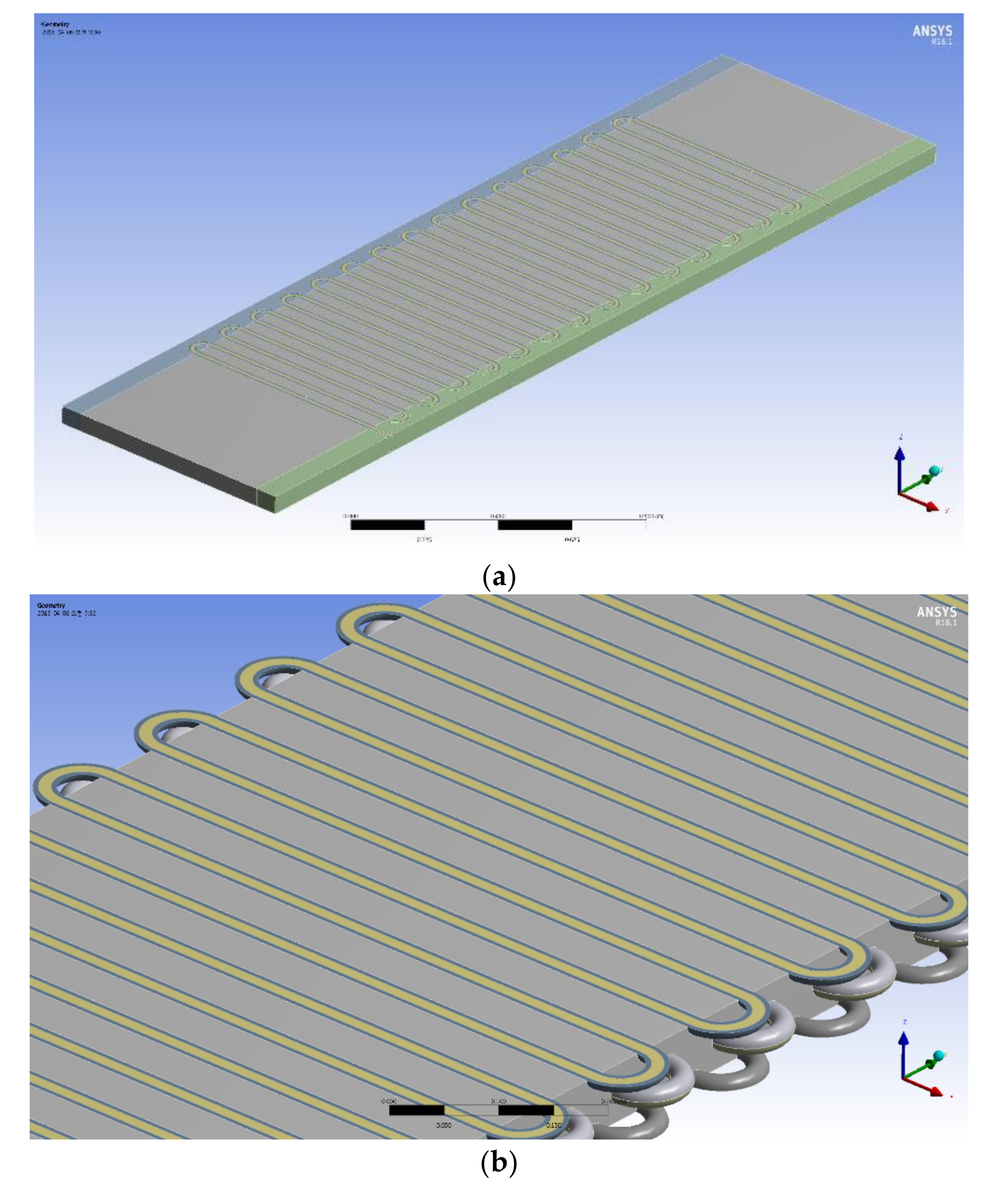
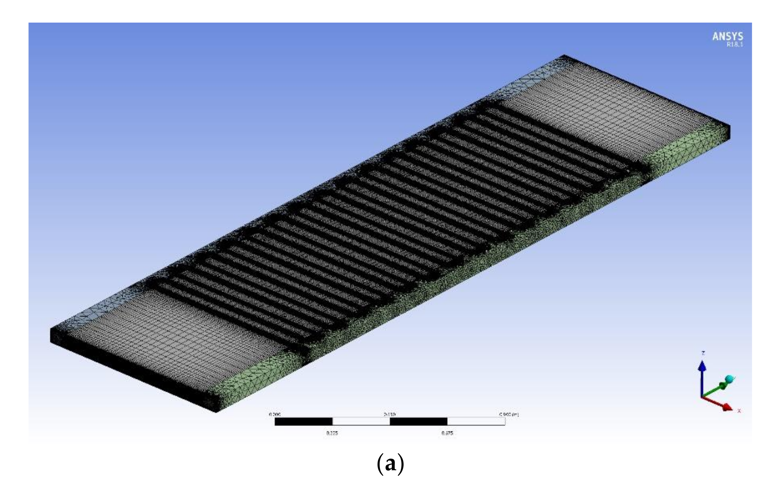
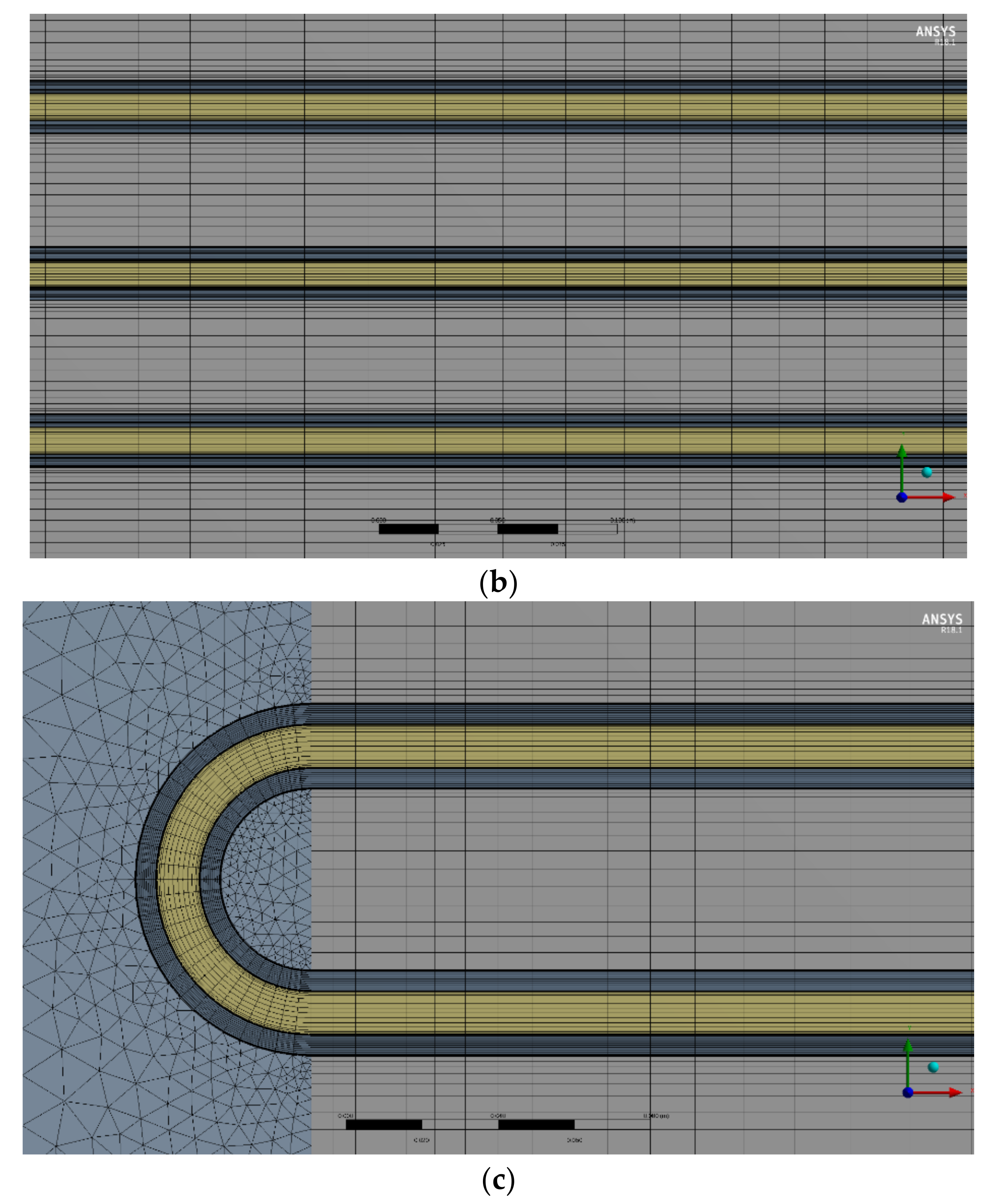
The thermal characteristics of the SCO2 heat exchanger were analyzed using a commercial CFD code, CFX. The overall performance simulation of the SCO2 heat exchanger was difficult due to the computing power. Therefore, a design of the scaled SCO2 heat exchanger was created for the CFD analysis. Figure 4 shows the scaled SCO2 heat exchanger: Figure 4a indicates the overall three-dimensional geometry, and Figure 4b illustrates the staggered tube array used in the flow CFD analysis. In the SCO2 heat exchange chamber, three heat exchanger tubes with a staggered tube array were positioned. The center of the heat exchanger tube reflected the full-scale tube specification, while the half-scale tube specification was considered in the bottom and top of the tubes. The numbers of nodes and elements for the analysis were 9,555,606 and 10,698,900, respectively. Figure 5 shows the mesh distributions on the scaled SCO2 heat exchanger. Figure 5a illustrates the overall mesh distributions in the scaled SCO2 heat exchanger, Figure 5b indicates the mesh structure around the straight tube position, and Figure 5c shows the mesh formation near the tube bending location. Precise cells near the wall surface were considered to keep the turbulence effect. Several grid layers were applied around the heat exchanger tubes to consider the wall effect on the working fluids.
For the turbulence model, a two-equation turbulence model of RNG k-ε was used: k is the turbulence kinetic energy, which is defined by the fluctuation in velocity, and ε is the turbulence eddy dissipation. The RNG k-ε model was improved from the standard k-ε model, and it was derived using the renormalization group theory. The RNG k-ε model has an additional term, which considers the eddy dissipation, average shear stress, and swirl effect. These features provide a more accurate turbulence model compared to the standard k-ε model. The transport equations for turbulence generation and dissipation are the same as those for the standard k-ε model, but the model constants differ [30].
For the continuity equation:
For the momentum equation:
For the transport equation for turbulence dissipation:
where ρ is the density, p’ is the modified pressure, μ is the viscosity, SM is the sum of body forces and Pk is the shear production of turbulence, while σεRNG, Cε1RNG constant, and Cε2RNG constant are the RNG k-ε constants.
The boundary conditions were based on the actual operation conditions of the SCO2 heat exchanger. For the actual SCO2 heat exchanger, the number of heat exchanger tubes was 16, as shown in Figure 1. Uniform mass flow distributions on each heat exchanger tube were assumed: the mass flow rate of the SCO2 in each tube was 0.0625 kg/s. For the flue gas in the scaled SCO2 heat exchanger, the mass flow rate was calculated as 0.1062 kg/s. The fluid properties were implemented in the CFD code with a real gas properties table format, using NIST REFPROP Database 23, Version 9.1 [25]. For the convergence criteria, the SCO2 outlet temperature was monitored in each step as well as solution imbalances (mass, momentum, and energy) less than 1%.
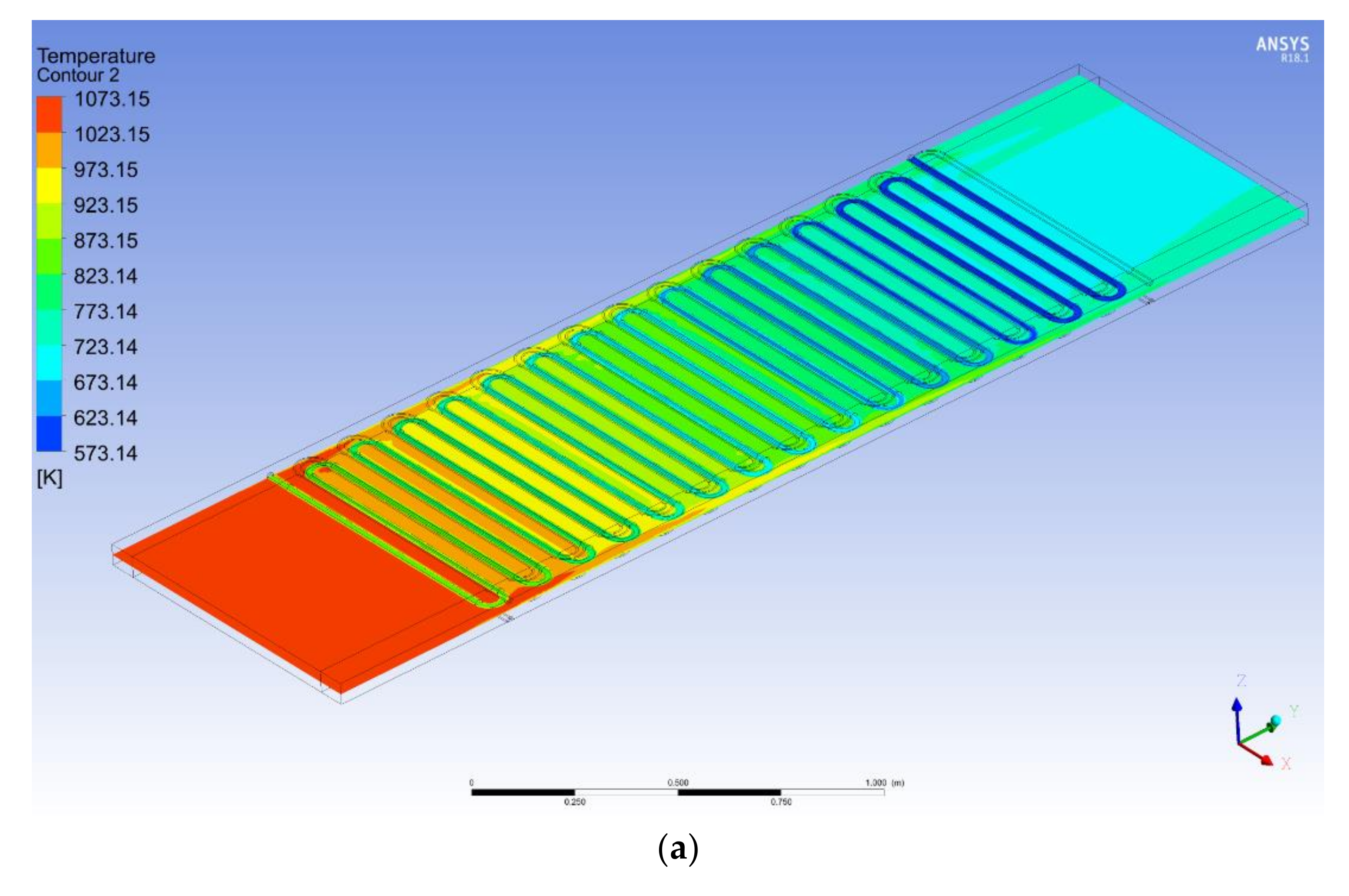
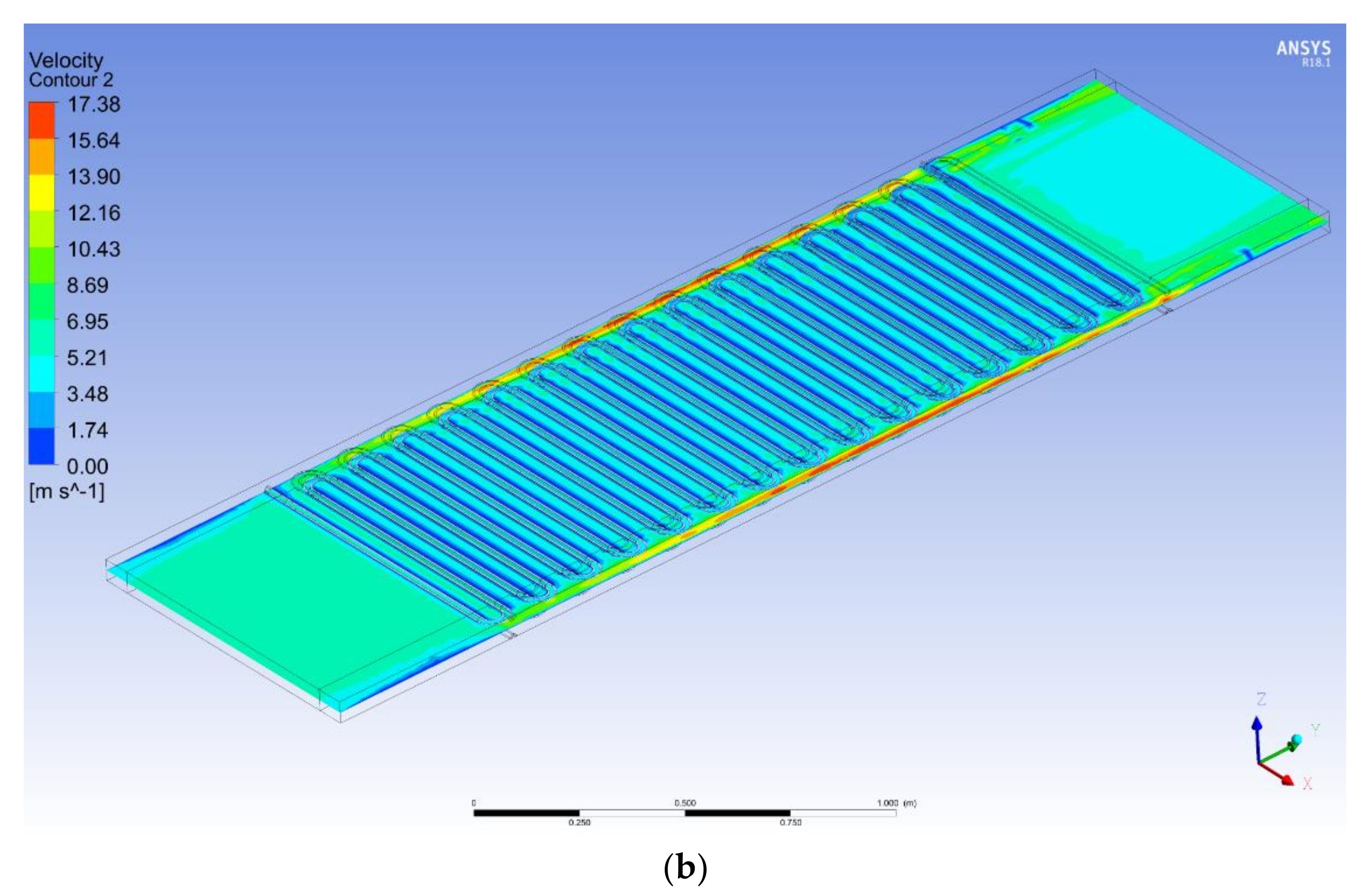
Figure 6 shows the CFD results for the center position of the SCO2 heat exchanger: Figure 6a,b show the temperature and velocity distributions, respectively. High-velocity regions were focused on the left and right sides of the SCO2 heat exchange chamber because there was empty space for installing the SCO2 heat exchanger and tube displacement margin due to the thermal stress. However, the in-house code did not consider the empty space at the corner of the SCO2 heat exchange chamber. The empty space could have resulted in different simulation results between the in-house code and the CFD analysis. However, the outlet temperature of the SCO2 showed a similar performance (602 °C) compared to the in-house code result. The pressure drop of the SCO2 flow path was calculated as 0.374 bar, which is lower than the design constraint. Further pressure drops should be considered in the heat exchanger headers and nozzles.
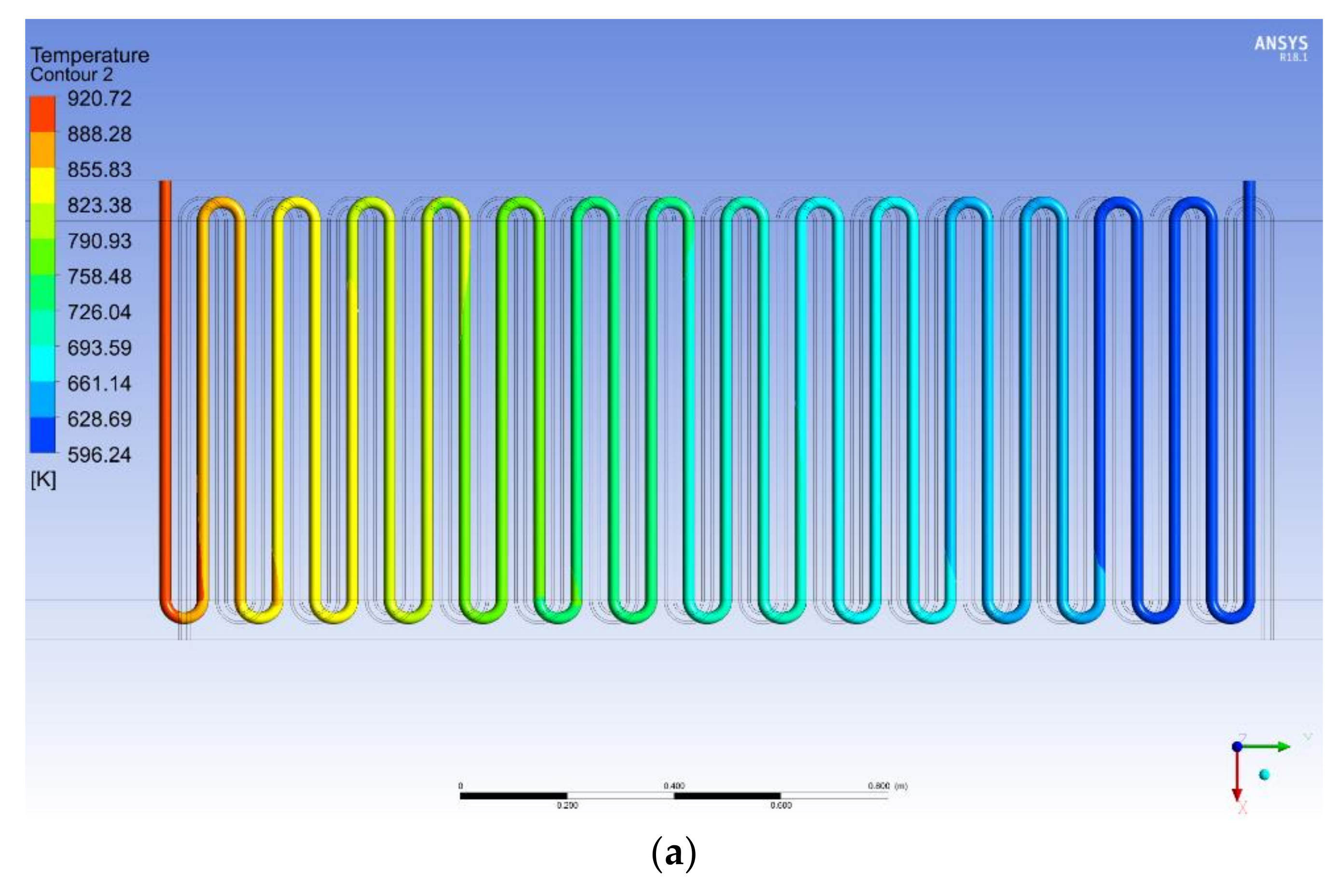
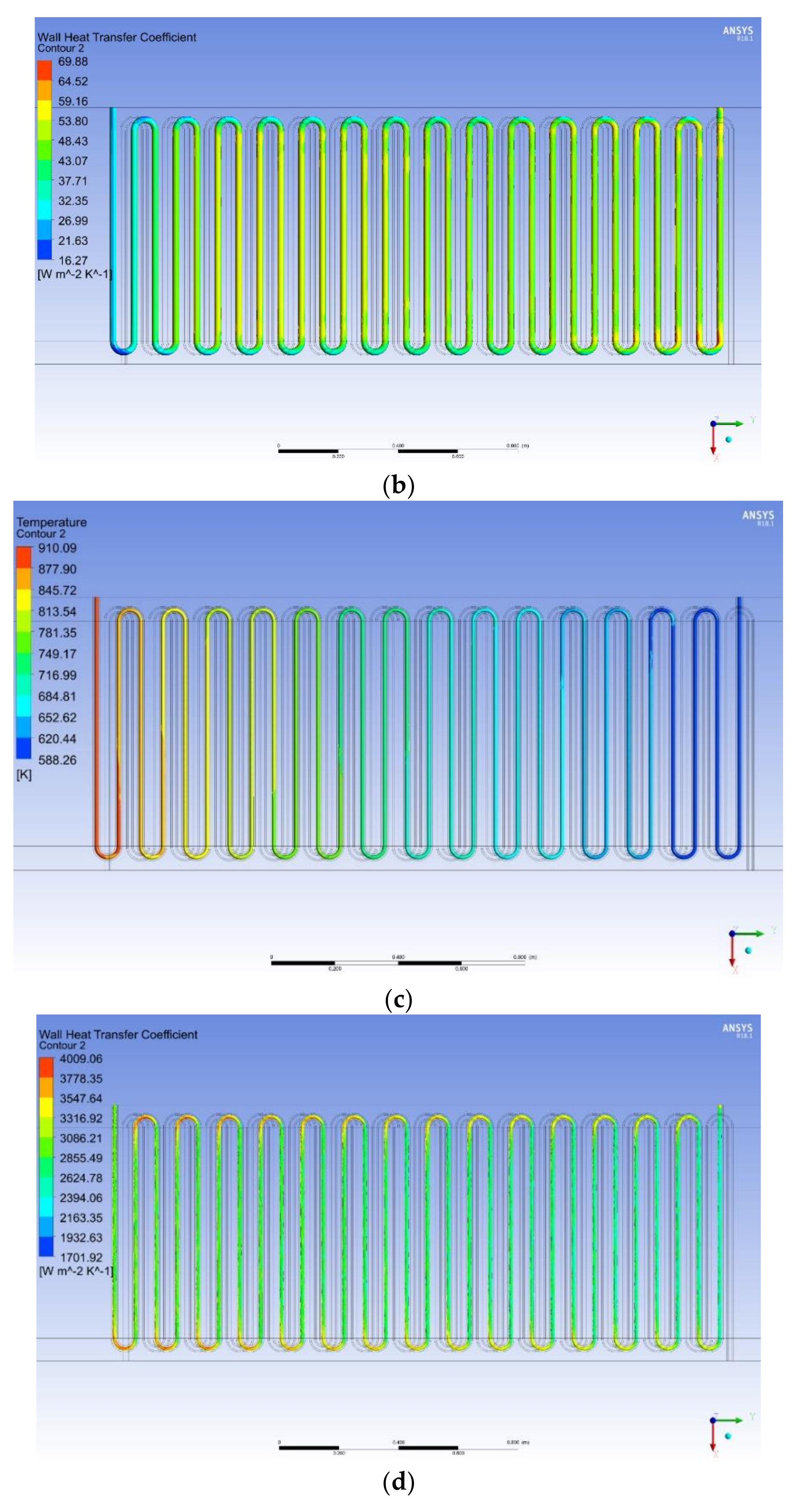
The temperature and heat transfer coefficient distributions on the heat exchanger are important because these parameters can influence the tube’s integrity. Figure 7 shows the temperature and heat transfer coefficient distributions on the inner and outer heat exchanger tubes. Figure 7a,b are the results of the tube’s outer surface and Figure 7c,d are the results of the tube’s inner surface. The tube’s maximum inner and outer surface temperatures were 647 °C and 637 °C, respectively. The tube’s maximum surface temperature was lower than the temperature assumption value (650 °C) in the heat exchanger material selection. For the tube’s inner area, the maximum heat transfer coefficient was about 4000 W/m2K, which was located at the tube’s bending location. For the outer tube area, the maximum heat transfer coefficient was located near the outlet position of the flue gas and was 70 W/m2K. Based on the temperature and heat transfer coefficient distributions on the heat exchanger tube, thermal stress analysis was performed.
4.2. Thermal Stress Analysis
To show the integrity of the SCO2 heat exchanger tube, thermal stress analysis was conducted using a commercial CFD code, ABAQUS [31]. High-temperature regions of the heat exchanger tube located near the SCO2 outlet region (flue inlet region) were analyzed. Therefore, 10 straight lines with 10 bending flow paths were modeled for the thermal stress simulation. With consideration of the symmetrical structure of the heat exchanger tube, a half scale of the heat exchanger tube was analyzed. 1,114,135 elements were used for the thermo-mechanical analysis. Three-dimensional continuum element DCC3D8 was used to obtain the temperature distribution, and the stress analysis was carried out using the C3D8 continuum solid element.
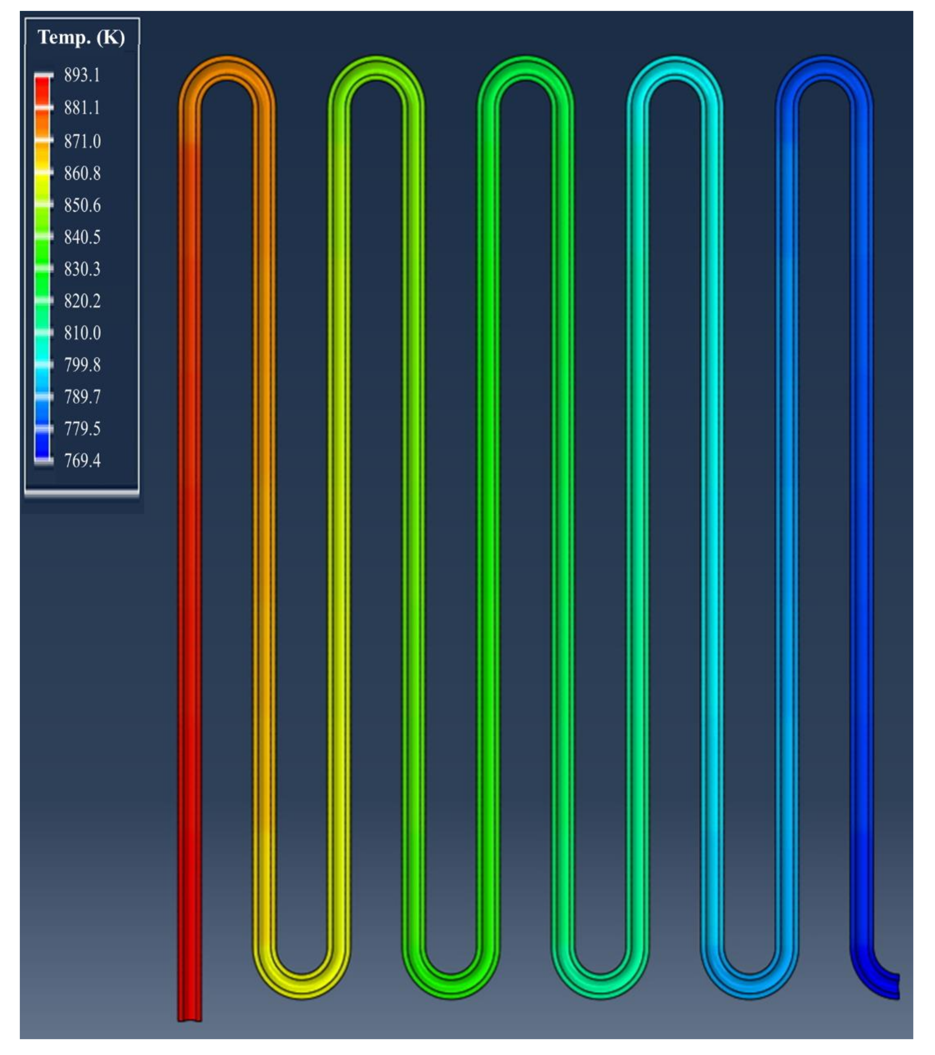
In order to obtain temperature distributions for the heat exchanger tube, temperature and heat transfer coefficient profiles obtained from the thermal analysis were used as the input for thermal stress analysis. Because the pressure drop in the heat exchanger and heat exchange chamber was negligible compared to the operating condition, the pressures in the SCO2 heat exchanger tube and the chamber were assumed to be 200 bar and atmospheric pressure, respectively. Figure 8 illustrates the temperature distribution in the scaled heat exchanger tube. A solid temperature of the heat exchanger tube is closer to the SCO2 temperature because the SCO2 heat transfer coefficient is higher than that of the flue gas. The evaluation of thermal stress analysis was based on the allowable stress value of S34709. The allowable stress value at a temperature of 650 °C is 539 bar, which is based on ASME Sec. II [23]. The finite element stress analysis was performed with three cases separately: (1) thermal loading, (2) pressure loading, and (3) thermal and pressure loading.
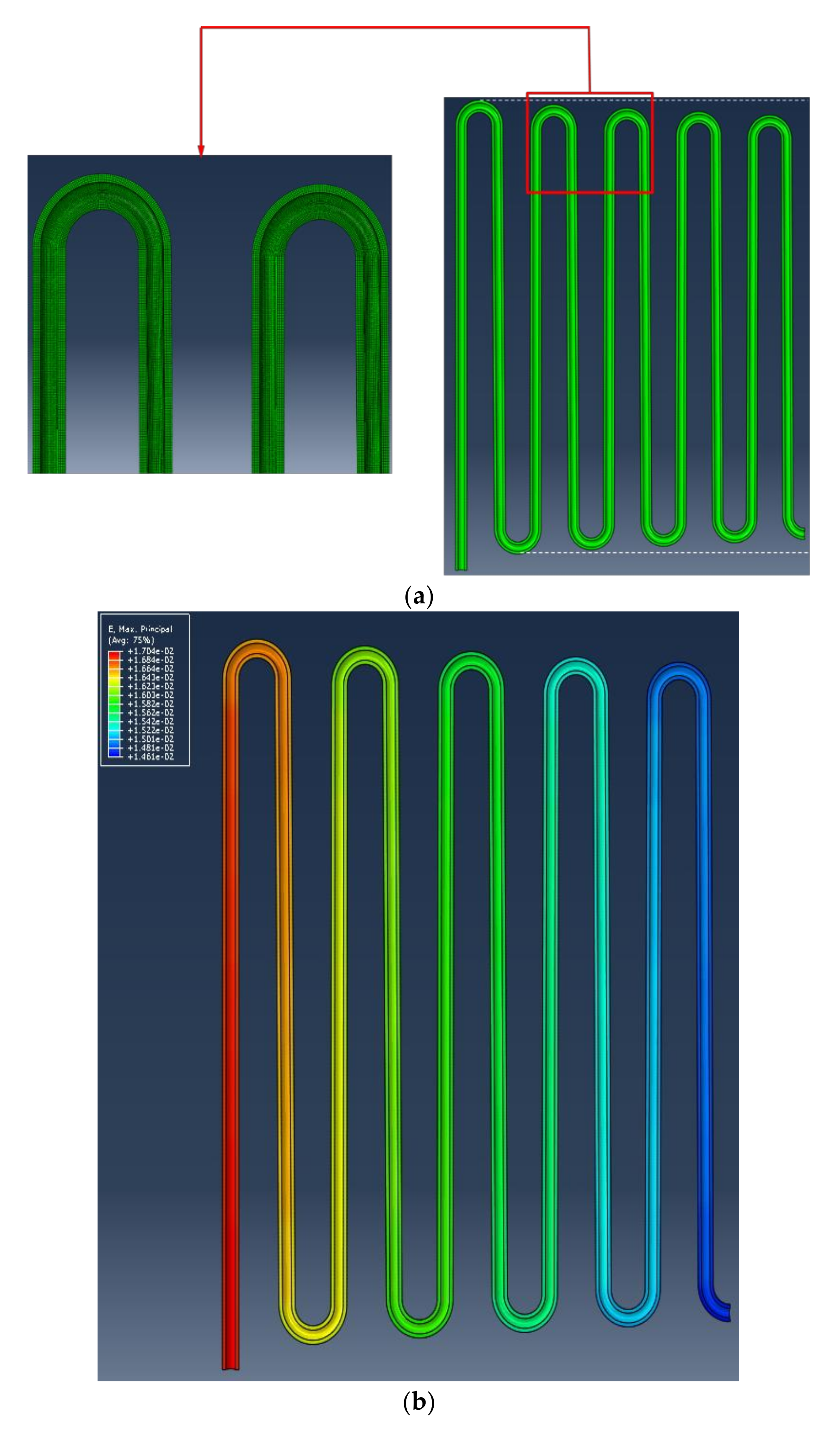
Figure 9 shows the tube displacement due to the temperature distribution in the heat exchanger tube. Figure 9a,b represent the tube displacement shape and the principal strain distributions, respectively. The high-temperature area near the exit of the SCO2 had a large tube expansion, and it gradually decreased. The principal strain distributions showed similar distributions compared to the tube displacement. The maximum principal strain value was discovered to be 0.017. If the deformation of the heat exchanger tube is not considered, thermal buckling due to excessive pressure stress can occur. In the present SCO2 heat exchanger design, empty space in the chamber was considered, which maintained the integrity of the tube even when the tube displacement appeared.
Von-Mises stress distributions are shown in Figure 10 along the scaled heat exchanger tube. Figure 10a,b are the results of the thermal and pressure loading cases, respectively. In the case of thermal loading, the maximum stress was found near the tube bending area. On the other hand, the maximum stress was located at the tube bending area for the pressure loading condition. The maximum local von-Mises stress values were 35.5 bar and 516 bar for the thermal and pressure loading cases, respectively. It was confirmed that these stress values were lower than the allowable stress value. Figure 10c is the result of thermal stress analysis considering both the thermal and pressure loading cases. The stress distributions in the tube were similar to the combination of the thermal and pressure loading cases. The maximum von-Mises value was calculated as 523 bar, which is lower than the allowable stress value considered in the present study. The stress evaluation loaded on the heat exchanger tube was conducted based on the ASME Sec. VIII. The membrane stress of the heat exchanger tube was 287 bar, while the allowable stress value was 539 bar. The sum of the membrane stress and the bending stress was 378 bar, which is lower than the constraint value (1.5 × allowable stress value = 808 bar). Therefore, the stress state of the SCO2 heat exchanger satisfied the ASME criteria.
5. Conclusions
This study focused on the design of an SCO2 heat exchanger for obtaining high-temperature and high-pressure heat exchange technologies under an SCO2 environment. A tubular type heat exchanger was selected because it has high durability in extreme conditions, such as having low pressure losses in both the hot and cold sides. The heat exchanger material selection was conducted based on the maximum allowable stress, corrosion resistance, cost, and availability. A staggered tube array with a counter-cross flow arrangement was determined and the overall size of the SCO2 heat exchanger was based on the tube bending criteria and the results of in-house heat exchanger performance code. Commercially available three-dimensional CFD codes were then used to analyze the flow and thermal characteristics of the SCO2 heat exchanger. The temperature and heat transfer coefficient distributions on the SCO2 heat exchanger were analyzed. Then, thermal stress analysis was conducted based on the obtained flow analysis results. The stressed state of the SCO2 heat exchanger was evaluated based on the ASME procedure. The membrane stress, bending stress, and local stress were lower than the allowable stress. The results indicate that the stress of the present heat exchanger satisfied the ASME criteria. Based on the design of the SCO2 heat exchanger, the manufacturing process can be performed.
Author Contributions
Conceptualization, H.S. and J.E.C.; Methodology, H.S. and J.E.C.; Software, H.S., J.K., and Y.-W.K.; Validation, H.S., J.K., and Y.-W.K.; Formal analysis, H.S., J.E.C., and I.S.; Investigation, H.S., J.K., and I.S.; Resources, H.S., Data Curation, H.S., J.K., and Y.-W.K.; Writing-Original Draft, H.S.; Writing-Review & Editing, J.E.C.; Visualization, H.S.; Supervision, H.S.; Project administration, H.S.; Funding acquisition, J.E.C. All authors have read and agreed to the published version of the manuscript.
Funding
This work was financially supported by the institute of Civil Military Technology Cooperation funded by the Defense Acquisition Program Administration and Ministry of Trade, Industry and Energy of Korean government under grant No. 17-CM-EN-04.
Conflicts of Interest
The authors declare no conflict of interest.
Nomenclature
| Nomenclature | |
| S | pitch |
| k | turbulence kinetic energy |
| P | pressure |
| T | temperature |
| P | shear production |
| U | velocity |
| Greek symbols | |
| ε | turbulence eddy dissipation |
| ρ | density |
| μ | viscosity |
| Subscripts | |
| c | critical |
| L | length |
| T | height |
References
- Feher, E.G. The Supercritical Thermodynamic Power Cycle. In Proceedings of the Intersociety Energy Conversion Engineering Conference, Miami Beach, FL, USA, 13–17 August 1967. Douglas Paper No. 4348. [Google Scholar]
- Angelino, G. Real Gas Effects in Carbon Dioxide Cycles. In Proceedings of the ASME 1969 Gas Turbine Conference and Products Show, Paper No. 69-GT-103. Cleveland, OH, USA, 9–13 March 1969. [Google Scholar]
- Dostal, V.; Driscoll, M.J.; Hejzlar, P. A Supercritical Carbon Dioxide Cycle for Next Generation Nuclear Reactors; MIT-ANP-TR-100; Massachusetts Institute of Technology: Cambridge, MA, USA, 2004. [Google Scholar]
- Wright, S.A.; Fuller, R.; Pickard, P.S.; Vernon, M.E. Initial status and test results from a supercritical CO2 Brayton cycle test loop. In Proceedings of the International Conference on Advances in Nuclear Power Plants, Anaheim, CA, USA, 8–12 June 2008. [Google Scholar]
- Wright, S.A.; Pickard, P.S.; Fuller, R.; Radel, R.F.; Vemon, M.E. Supercritical CO2 Brayton cycle power generation development program and initial results. In Proceedings of the ASME Power Conference, Albuquerque, NM, USA, 21–23 July 2009. [Google Scholar]
- Wright, S.A.; Radel, R.F.; Vernon, M.E.; Rochau, G.E.; Pickard, P.S. Operation and Analysis of a Supercritical CO2 Brayton Cycle; SAND2010-0171; Sandia National Laboratories: California, CA, USA, 2010. [Google Scholar]
- Clementoni, E.M.; Cox, T.L.; Sprague, C.P. Startup and operation of a supercritical carbon dioxide Brayton cycle. ASME J. Eng. Gas Turbines Power 2014, 136, 071701. [Google Scholar] [CrossRef]
- Clementoni, E.M.; Cox, T.L.; King, M.A. Off-nominal component performance in a supercritical carbon dioxide Brayton cycle. ASME J. Eng. Gas Turbines and Power 2016, 138, 011703. [Google Scholar] [CrossRef]
- Clementoni, E.M.; Cox, T.L.; King, M.A. Steady-State Power Operation of a Supercritical Carbon Dioxide Brayton Cycle; ASME Turbo Expo: Seoul, Korea, 2016. [Google Scholar]
- Held, T.J. Initial test results of a megawatt-class supercritical CO2 heat engine. In Proceedings of the 4th International Supercritical CO2 Power Cycles Symposium, San Antonio, TX, USA, 9–10 September 2014. [Google Scholar]
- Held, T.J. Commercialization of Supercritical CO2 Power Cycles. In Proceedings of the 1st European Seminar on Supercritical CO2 Power Systems, Vienna, Austria, 29–30 September 2016. [Google Scholar]
- Moore, J.; Brun, K.; Evans, N.; Kalra, C. Development of 1 MWe supercritical CO2 test loop. In Proceedings of the ASME Turbo Expo, Montreal, QC, Canada, 15–19 June 2015. [Google Scholar]
- Hoopes, K.; Rimpel, A. Development of a 2.6MW heater for SUNSHOT sCO2 turbine mechanical test. In Proceedings of the 5th International Supercritical CO2 Power Cycles Symposium, San Antonio, TX, USA, 28–31 March 2016. [Google Scholar]
- Moore, J.; Cich, S.; Day, M.; Allison, T.; Wade, J.; Hofer, D. Commissioning of a 1 MWe supercritical CO2 test loop. In Proceedings of the 6th International Supercritical CO2 Power Cycles Symposium, Sacramento, CA, USA, 27–29 March 2018. [Google Scholar]
- Department of Energy (DOE). Energy Department Announces New Investments in Supercritical Transformational Electric Power Program. Available online: https://www.energy.gov/ne/articles/energy-department-announces-new-investments-supercritical-transformational-electric#:~:text=WASHINGTON%20%2D%2D%20The%20U.S.%20Department,electrical)%20Supercritical%20Carbon%20Dioxide%20 (accessed on 15 December 2015).
- Bush, V. GTI STEP forward on sCO2 power. In Proceedings of the 6th International Supercritical CO2 Power Cycles Symposium, Sacramento, CA, USA, 27–29 March 2018. [Google Scholar]
- Huang, M.; Tang, C.; McClung, A. Steady state and transient modeling for the 10 MWe SCO2 test facility program. In Proceedings of the 6th International Supercritical CO2 Power Cycles Symposium, Sacramento, CA, USA, 27–29 March 2018. [Google Scholar]
- Cha, J.E.; Ahn, Y.; Lee, J.; Lee, J.I.; Choi, H.L. Installation of the Supercritical CO2 Compressor Performance Test Loop as a First Phase of the SCIEL facility. In Proceedings of the 4th International Supercritical CO2 Power Cycles Symposium, Pittsburgh, PA, USA, 9–10 September 2014. [Google Scholar]
- Cha, J.E.; Bae, S.W.; Lee, J.; Cho, S.K.; Lee, J.I.; Park, J.H. Operation Results of a Closed Supercritical CO2 Simple Brayton Cycle. In Proceedings of the 5th International Supercritical CO2 Power Cycles Symposium, Chicago, IL, USA, 28–31 March 2016. [Google Scholar]
- Cho, J.; Shin, H.; Ra, H.; Lee, G.; Rho, C.; Lee, B.; Baik, Y. Research on the development of a small-scale supercritical carbon dioxide power cycle experimental test loop. In Proceedings of the 5th International Supercritical CO2 Power Cycles Symposium, Chicago, IL, USA, 28–31 March 2016. [Google Scholar]
- Cho, J.; Shin, H.; Cho, J.; Ra, H.; Roh, C.; Lee, B.; Lee, G.; Choi, B.; Baik, Y. Preliminary power generating operation of the supercritical carbon dioxide power cycle experimental test loop with a turbo-generator. In Proceedings of the 6th International Supercritical CO2 Power Cycles Symposium, Sacramento, CA, USA, 27–29 March 2018. [Google Scholar]
- Natesan, K.; Moisseytsev, A.; Majumdar, S. Preliminary Issues Associated with the Next Generation Nuclear Plant Intermediate Heat Exchanger Design. J. Nucl. Mater. 2009, 392, 307–315. [Google Scholar] [CrossRef] [Green Version]
- ASME Boiler and Pressure Vessel Committee on Materials. ASME Boiler and Pressure Vessel Code Section II; American Society of Mechanical Engineers (ASME): New York, NY, USA, 2015. [Google Scholar]
- ASME Boiler and Pressure Vessel Committee on Materials. ASME Boiler and Pressure Vessel Code Section III; American Society of Mechanical Engineers (ASME): New York, NY, USA, 2015. [Google Scholar]
- Lemmon, E.W.; Huber, M.L.; McLinden, M.O. NIST Standard Reference Database 23: Reference Fluid Thermodynamic and Transport Properties-REFPROP, Version 9.1; National Institute of Standards and Technology: Gaithersburg, DC, USA, 2013. [Google Scholar]
- Zukauskas, A.A. High-Performance Single-Phase Heat Exchangers; Hemisphere Publishing Corp.: New York, NY, USA, 1989. [Google Scholar]
- Zukauskas, A.A.; Makarevicius, V.J.; Slanciauskas, A.A. Heat Transfer in Banks of Tubes in Crossflow of Fluid; Thermophysics 1; Mintis: Vilnius, Lithuania, 1968; pp. 47–68. [Google Scholar]
- Gnielinski, V. New Equations for Heat and Mass Transfer in Turbulent Pipe and Channel Flow. Int. Chem. Eng. 1976, 16, 359–368. [Google Scholar]
- Shah, R.K.; Sekulic, D.P. Fundamentals of Heat Exchanger Design; John Wiley and Sons, Inc.: Hoboken, NJ, USA, 2003. [Google Scholar]
- ANSYS. ANSYS CFX-Solver Theory Guide; ANSYS, Inc.: Canonsburg, PA, USA, 2017. [Google Scholar]
- ABAQUS/CAE. User’s Guide Version; Dassault Systems Simulia Corp.: Providence, RI, USA, 2013. [Google Scholar]
Figure 1.
Schematic of the SCO2 heat exchanger tube bundle.

Figure 2.
SCO2 heat exchanger header, nozzle, and tube-supporting structure.

Figure 3.
Heat exchanger performance analysis flow chart.

Figure 4.
Scaled SCO2 heat exchanger; (a) overall CFD analysis structure; (b) detailed view around heat exchanger tubes.
Figure 4.
Scaled SCO2 heat exchanger; (a) overall CFD analysis structure; (b) detailed view around heat exchanger tubes.

Figure 5.
Mesh distributions on the scaled SCO2 heat exchanger: (a) overall mesh distributions, (b) mesh distributions around the straight tube position, (c) mesh formation near the tube bending area.
Figure 5.
Mesh distributions on the scaled SCO2 heat exchanger: (a) overall mesh distributions, (b) mesh distributions around the straight tube position, (c) mesh formation near the tube bending area.


Figure 6.
CFD results at the centerline of the scaled SCO2 heat exchanger: (a) temperature and (b) velocity distributions.
Figure 6.
CFD results at the centerline of the scaled SCO2 heat exchanger: (a) temperature and (b) velocity distributions.


Figure 7.
CFD results around the heat exchanger tube: (a) temperature distributions on the outer tube surface, (b) heat transfer coefficient distributions on the outer tube surface, (c) temperature distributions on the inner tube surface, (d) heat transfer coefficient distributions on the inner tube surface.


Figure 8.
Heat exchanger tube temperature distributions used in the thermal stress analysis.

Figure 9.
Tube displacements on the tube: (a) tube displacement shape, (b) the maximum principal strain distributions.
Figure 9.
Tube displacements on the tube: (a) tube displacement shape, (b) the maximum principal strain distributions.

Figure 10.
Von-Mises stress distributions: (a) thermal loading, (b) pressure loading, (c) thermal and pressure loading cases.
Figure 10.
Von-Mises stress distributions: (a) thermal loading, (b) pressure loading, (c) thermal and pressure loading cases.


Table 1.
Operating condition of the SCO2 heat exchanger.
| Design Parameters | Operating Condition |
|---|---|
| Mass flow rate (SCO2) | 1 kg/s |
| Outlet pressure (SCO2) | 200 bar |
| Inlet & Outlet temperature (SCO2) | 300 & 600 °C |
| Flue gas inlet temperature | 800 °C |
| Outlet pressure (flue gas) | atmospheric pressure |
© 2020 by the authors. Licensee MDPI, Basel, Switzerland. This article is an open access article distributed under the terms and conditions of the Creative Commons Attribution (CC BY) license (http://creativecommons.org/licenses/by/4.0/).
Share and Cite
MDPI and ACS Style
Seo, H.; Cha, J.E.; Kim, J.; Sah, I.; Kim, Y.-W. Design and Performance Analysis of a Supercritical Carbon Dioxide Heat Exchanger. Appl. Sci. 2020, 10, 4545. https://doi.org/10.3390/app10134545
AMA Style
Seo H, Cha JE, Kim J, Sah I, Kim Y-W. Design and Performance Analysis of a Supercritical Carbon Dioxide Heat Exchanger. Applied Sciences. 2020; 10(13):4545. https://doi.org/10.3390/app10134545
Chicago/Turabian StyleSeo, Han, Jae Eun Cha, Jaemin Kim, Injin Sah, and Yong-Wan Kim. 2020. "Design and Performance Analysis of a Supercritical Carbon Dioxide Heat Exchanger" Applied Sciences 10, no. 13: 4545. https://doi.org/10.3390/app10134545
Note that from the first issue of 2016, this journal uses article numbers instead of page numbers. See further details here.