Investigation of a Radial Turbine Design for a Utility-Scale Supercritical CO2 Power Cycle

1
Centre for Energy and Power, School of Water Energy and Environment, Cranfield University, Cranfield MK43 0AL, UK
2
Centre for Propulsion Engineering, School of Aerospace Transport and Manufacturing, Cranfield University, Cranfield MK43 0AL, UK
*
Author to whom correspondence should be addressed.
Appl. Sci. 2020, 10(12), 4168; https://doi.org/10.3390/app10124168
Submission received: 26 May 2020
/
Revised: 10 June 2020
/
Accepted: 12 June 2020
/
Published: 17 June 2020
(This article belongs to the Special Issue Recent Advancement of Thermal Fluid Engineering in the Supercritical CO2 Power Cycle)
Abstract
:This paper presents the design procedure and analysis of a radial turbine design for a mid-scale supercritical CO power cycle. Firstly, thermodynamic analysis of a mid-range utility-scale cycle, similar to that proposed by NET Power, is established while lowering the turbine inlet temperature to 900 C in order to remove cooling complexities within the radial turbine passages. The cycle conditions are then considered for the design of a 100 MW power scale turbine by using lower and higher fidelity methods. A 510 mm diameter radial turbine, running at 21,409 rpm, capable of operating within a 5% range of the required cycle conditions, is designed and presented. Results from computational fluid dynamics simulations indicate the loss mechanisms responsible for the low-end value of the turbine total-to-total efficiency which is 69.87%. Those include shock losses at stator outlet, incidence losses at rotor inlet, and various mixing zones within the passage. Mechanical stress calculations show that the current blade design flow path of the rotor experiences tolerable stress values, however a more detailed re-visitation of disc design is necessitated to ensure an adequate safety margin for given materials. A discussion of the enabling technologies needed for the adoption of a mid-size radial turbine is given based on current advancements in seals, bearings, and materials for supercritical CO cycles.
1. Introduction
In compliance with the warnings of the Intergovernmental Panel on Climate Change [1] to limit CO discharges and keep the global temperature rise below 1.5 C, techniques for mitigating power generation emissions are being widely investigated; examples range from using non-conventional working fluids and increasing the efficiency of power plants to implementing carbon capture and storage (CCS) [2]. Oxy-combustion appears to be the most favourable CCS route because of the simple separation of carbon dioxide from the steam present in the flue gases [3]. The basis of this method is that a fuel is combusted with pure oxygen to produce a stream of exhaust gases consisting mainly of HO and CO which can be separated downstream through condensation [4].
With respect to unconventional working fluids, supercritical CO (sCO) cycles are attracting growing interest due to the advantages associated with the fluid. The attractiveness of the use of sCO fluid is based on its availability and inertness as well as the consistently cited advantages of such power cycles [5]:
- The nature of the high density sCO fluid means that power conversion systems are very compact compared to conventional power cycles [6] (≈ 30 times smaller than steam cycles and ≈ 6 times smaller than air cycles)
- High cycle efficiencies are also obtained, attributed to lower pumping power requirements and the non-ideal gas properties of sCO which translate into lower fuel consumption and lower capital and operating costs. Targeted efficiencies of large-scale, closed supercritical CO Brayton cycles approach 50%
- The suitability of the cycle for waste heat recovery from a variety of heat sources (e.g., nuclear, solar, fossil, geothermal, etc.)
- The application of these high-efficiency cycles reduces greenhouse gas effects because a CO emission is used as a working fluid or as a recycle stream (i.e., not emitted)
- The suitability of sCO cycle systems for use in arid climates because of their ability to use dry cooling (thus saving water) [7]
- Low purification requirements for fluid leakages because the cycle operates above the critical pressure of CO
The NET Power (Allam) cycle combines both originalities of oxy-combustion and supercritical CO fluids in one system which is aimed at high power generation efficiencies coupled with high levels of CO capture [8]. A review of oxy-combustion cycles has been reported by the International Energy Agency (IEA) identifying the main cycle configurations, requirements, benefits, complications and future developments by presenting cycle modelling and techno-economic study results [9]. The NET Power is one of the most attractive of the listed oxy-combustion cycles in terms of efficiency reaching 55% on lower heating value of fuel (LHV). Natural gas fuel or coal and oxygen from an air separation unit are combusted at high temperatures reaching 1200 C at high pressures (≈ 30 MPa) with the recirculated CO; due to the absence of N in the combustion process, the flue gases are mostly composed of CO and HO with no formation of NO (for a natural gas based cycle). The combustion products are then expanded in the CO turbine with a pressure ratio between 6 and 12 before entering a multi-flow economizer heat exchanger where the turbine cooling flow and the recycled CO and O streams to the combustor are pre-heated using the residual flue gas heat [10]. The exhaust stream is also cooled for condensation and separation of water from the mixture. A fraction of the remaining (mostly pure) CO stream is sent for carbon capture and storage while the rest is re-compressed and used as a temperature moderator in the combustor through mixing with the O coming from the ASU [11]. Cooling of the combustor and turbine components to allow operation at the relatively high turbine inlet temperature of 1200 C is more complex than in a conventional combined cycle gas turbine where cooling air can be bled directly from the compressor section. For the Allam cycle, the available cooling fluid is the CO stream, unless a closed loop system is implemented using a different fluid, e.g., steam, although this would add cost as there is no steam available in the cycle. This constraint could limit the cycle from further efficiency improvements through increased turbine entry temperature due to the counterbalancing cooling penalty.
One of the most critical barriers that inhibits the full-scale development of the novel NET Power cycle is the design of the high-pressure, high temperature turbine which dictates cooling requirements, material considerations and number of stages to name a few. The turbine operates at an unorthodox combination of high temperatures, comparable to those of gas turbines, and high pressures, analogous to steam plants, in the presence of unconventional working fluids. The design of a proposed and undisclosed axial turbine, developed by Toshiba [12], requires intricate cooling passages within the small-sized blades, hence poses significant constraints on the design thereby limiting aerodynamic performance and manufacturability. A radial turbine, which generally has a simpler construction and fewer stages when compared to its axial contestant, is suggested as a superior candidate arrangement for such cycles of high fluid density. For these reasons, the NET Power theme is taken as the basis of a paradigm cycle configuration around which restrictions of a radial turbine design can be applied. A thermodynamic analysis of a mid-range cycle is established while lowering the turbine inlet temperature to remove cooling complications within the radial turbine passages. The cycle conditions are then considered for the design of a multi-MW scale turbine by using lower-order preliminary and higher fidelity methods.
The focus of this paper is the analysis of the results from a single satisfactory radial turbine design which is obtained based on the identified cycle requirements. It aims at highlighting the flow behaviour within the blade passages as opposed to solely trying to optimise a turbine design. Eventually, the methods are used to provide the necessary understanding of the loss mechanisms specific to sCO radial turbines at such power scales, which in turn allow the identification of possible areas for re-design.
2. Modelling Methodology
The overall methodology followed throughout this piece of work is summarised in the flowchart of Figure 1. The main steps of the adopted modelling sequence are explained in the following Subsections. Initially, an uncooled cycle model is developed to obtain the turbine operating conditions required for the turbine design. The design procedure begins by performing initial calculations employing a meanline design code, and it is followed by generating a wide range of turbine geometries via preliminary design tools. The following stage involves the analysis of a set of the preliminary designs using 2D throughflow calculations where only a select few are taken further down the performance investigation using more advanced computational fluid dynamics (CFD) modelling. This is an iterative process until a suitable design that meets defined aerodynamic performance criteria is identified. Structural assessment is then performed for the chosen design to investigate the mechanical integrity of the rotor in operation.
2.1. Cycle Modelling
The licensed software Aspen Plus V9 [13] is used for simulating the cycle, which is based on the initial model of the work of Scaccabarozzi et al. [10], to obtain the necessary data for turbine design which include working fluid ratios, power output, flow rates, as well as temperatures and pressures. Cycle modelling and analysis are performed before detailed geometrical information or structural aspects of components are defined.
The cycle considered in this work is a modification of the NET Power cycle introduced in Section 1. The changes include a reduced turbine inlet temperature and a lower pressure ratio; the uncooled turbine case is considered as a datum configuration for the following reasons:
- One of the benefits of a supercritical CO cycle is small turbomachinery components which implies small blades that require intricate passages if cooling is employed. The design complexities associated with cooling are eliminated by the use of a smaller-scale radial turbine design
- Smaller power output scale so that a radial turbine can still be within acceptable efficiency ranges (power limit shown in Section 3.1.2)
- There is a lack of experience in radial turbine cooling for such high temperatures
The layout of the modified cycle under study is very similar to that in the work of Scaccabarozzi et al. [10]. Alterations to the original NET Power cycle model include the absence of cooling flows in the turbine (thus only one turbine component) and regenerator, plus the use of two flow compressors instead of four.
2.2. Meanline Design
The turbine operating conditions obtained from the cycle model are used in this intermediate step to give an insight on the possible performance range and geometric dimensions of the radial expander. A meanline design tool is developed using MATLAB by coding established turbomachinery equations.
The programme NIST REFPROP has been cited widely throughout the literature for defining the thermodynamic and transport properties in sCO turbomachinery design tools [14,15,16,17]. It provides thermophysical properties of pure and compound fluids over a broad range of states for liquids, gases and supercritical phases based on validated data and calculation methods.
The initial design procedure is carried out using a meanline approach, which assumes one-dimensional passage conditions at mean radius of the turbomachine. The meanline aerodynamic design procedure of this work follows the approach introduced by Aungier [18] that can encompass the full operating range of a radial turbine. This method is used to determine the outline geometry of the turbine, given specific inputs, and to investigate the dependency of overall performance (size, efficiency, power) on key design parameters and assumptions such as specific speed and operating conditions [19]. Within the MATLAB tool, the estimate of the turbomachinery efficiency is obtained without the integration of loss models as these get incorporated in later stages of design. The main goal of this step is to obtain a range of turbine size parameters for use in the preliminary design tool of AxSTREAM in Section 2.3.
2.3. Preliminary Design
The proceeding design methodology tasks employ the integrated suite of turbomachinery design tools, AXSTREAM, licensed by SoftInWay.
The preliminary design (PD) tool from AxSTREAM enables the fast computation to generate several possible turbine flow path designs for a set of given boundary conditions (pressure ratio, mass flow rate, range of rotational speed, flow coefficient) taking into account specified geometric constraints. The model follows a similar procedure to the meanline preliminary design process cited in Section 2.2, relying on the assignment of stage pressure drop and degree of reaction as independent variables of energy, continuity, state and process one-dimensional, steady, equilibrium and adiabatic equations. Firstly, velocity coefficients are refined to meet the criteria of the selected empirical design model, then losses are computed after obtaining a possible flow path, followed by the re-iteration of cascade angles for supersonic flows, and finally the definition of blade profiles is performed after obtaining flow angles.
The inverse task calculation of the preliminary design solves a set of equations, with the implementation of inlet and outlet boundary conditions, to search for the criteria of unknown flow angles as a function of generated design variables—flow coefficient and stage loading (both which relate to turbomachinery losses)—that are based on existing correlations. Details about the theoretical and mathematical background of the preliminary design tool can be found in [20]. Although there is a major three-dimensional aspect to the flow in a radial turbine, an approximate verification of 1D formulation is used in the PD step to provide an estimation of sizing data that depend heavily on the selected empirical loss methods [21].
The initial estimates obtained from the MATLAB meanline code (without loss models) are used as input data to AxSTREAM. The preliminary design tool generates a large pool of design solutions based on the given boundary data and geometric constraints. The particular license of the software employed does not provide the capability of having a fluid mixture (such as that present in the cycle) so the working fluid is taken as pure supercritical CO assigned by the AxS Carbon Dioxide property method which is a modified Redlich-Kwong equation of state that covers a wide range of pressures and enthalpies [22]. Default empirical methods and loss models for radial turbines embedded in AxSTREAM are used in the design tasks.
All the generated turbine solutions can be explored in depth in the counterpart of the PD tool of AxSTREAM, the design space explorer, where designs are filtered through by applying constraints and limitations to allow trade-offs between power, efficiency, geometric design and velocities. Table 1 shows the filters applied to the design space to narrow the results selection process. The turbine solutions that do not meet the pre-defined constraints are automatically discarded and the selected designs can be examined in terms of flow path geometry. This option also allows for a quick study of the influence of crucial parameters on performance and size at the early stages of preliminary design.
2.4. Turbine Throughflow Analysis
The selected turbines from the preliminary design step are then analysed using the throughflow tool of AxSTREAM. Meanline analysis can be performed by using only the mean curvature section of the blade. Whereas a more refined streamline benchmarking calculation is done using the direct solver that considers the cascade geometry at hub, mid-span and tip for both stator and rotor. Kinematic and thermodynamic parameters are obtained along the blade height at three sections (hub, mid-span and tip). The aim is to get more precise performance parameters of the turbine before proceeding to blade profiling and design if needed.
Once a number of results are obtained for a select number of turbines, the user can start the post-design process of reviewing and editing the turbine flow path if needed; turbines that have not shown good performance or have not achieved solution convergence are discarded at this step instead of trying to optimise and edit the design. The outcome of the streamline calculations include loss and velocity charts, updated velocity triangles, meridional flow path and the enthalpy- entropy diagram, all which can be saved to the main project database to override performance results from the PD step. The project database will hold all relevant turbine information for each section (hub, mean, tip) as well as details on geometric and loss values for the design. Another check on the required constraints is performed in case any design fails to meet the criteria so as not carry it further to higher fidelity simulations.
2.5. Computational Fluid Dynamics
AxSTREAM provides tools that generate geometries based on 1D meanline design and allows analysis using higher fidelity models ranging from streamline analysis, axi-symmetric 2D and 3D computational fluid dynamics (CFD). AxCFD is the tool used for pre-processing, mesh generation, calculation and results post-processing. This step allows for the evaluation of the designed flow path, the comparison of results between the different calculation models (meanline, streamline, 3D CFD), and the understanding of flow mechanisms within the turbine.
The turbine domain employing a mixing plane halfway between stator trailing edge and rotor leading edge is simulated using AxCFD. Boundary conditions, of P = 297 bar, T = 1173 K and P = 54.0 bar, and working parameters are taken directly from the AxSTREAM project case saved after the 2D analysis with values taken as spanwise averages of quantities at hub, mean and tip sections. Rotational speed and mass flow rate are also automatically inherited from the project database but are altered for off-design simulations. Like other CFD tools, AxCFD solves decomposed Reynolds-Stress-Averaged Navier Stokes (RANS) equations with time-averaged density, pressure and energy conservation, and mass-averaged velocity equations in discretised fluid domains.
Passage mesh creation is required before any aerodynamic assessment of the turbine. The way of defining the size and number of the mesh elements in AxCFD is through mesh quality, a value ranging between 1 (coarsest) and 10 (finest). A mesh sensitivity study is performed, with results discussed in Section 3.3.1, to allow for a compromise between accuracy (mesh refinement) and computational time. Structured HO-type mesh elements with the same quality in hub-to-shroud and blade-to-blade directions are used in all cases with additional parameters for mesh adjustment; values are taken based on recommendations by SoftInWay.
The meshing zones defined by points on leading edge (LE) and trailing edge (TE) are modified manually over the blade profile contour for hub and tip sections. A mesh quality check is performed; good quality elements are described as those with no Jacobian determinant less than 0.3 and no (or minimal) angle parameter less than 12.
The k- SST turbulence model is used for its suitability in viscous turbomachinery simulations based on previous experience [23,24,25], with a medium turbulence intensity of 5%. The first order upwind scheme is employed due to convergence difficulties when using second-order. Slightly fluctuating trends and considerably high value criteria for some residuals in the range of 10 are accepted for simulations of similar applications shown in [26,27], but convergence is also checked against inlet/outlet mass imbalance of within 0.2%. AxCFD also allows calculations over 2D spanwise fluid domain sections via axi-symmetric modelling which is used of off-design performance map generation.
3. Results
3.1. Cycle Modelling
Before proceeding to process modelling of the fully modified cycle and using it as a basis for turbine design, it is reasonable to try and understand if there are any cycle benefits which can be credited to the removal of turbine cooling beyond that of reducing design complexities. From a practical point, a comparison between thermodynamically-identical cycles is conducted where cooling is the only limiting distinction.
3.1.1. Cooled Cycle Comparison
In an attempt to compare the performance of an uncooled cycle (the target cycle of this work) to a cooled one, like-for-like working conditions are applied. Conditions of the optimised cycle model from the work of Scaccabarozzi et al. are adopted [10] which are compared against the data from IEA GHG report [9]. Optimisation work, to achieve maximum cycle efficiency target, was carried out by the authors of [10] after performing a sensitivity analysis on the most relevant cycle-affecting parameters. The thermal energy of the feedstock is kept the same as in the cited works by setting the natural gas inlet flow rate to 16.52 kg/s. For the sake of comparison, the uncooled turbine is assumed to be capable of operating at a full-size (≈700–800 MW) power scale.
The comparison between a number of cycle performance results is viewed in Table 2. Generally there is good agreement in the results with some discrepancies that can be attributed to the differences in minor quantitative assumptions, and because of using two compression stages instead of four [10] which lowers the power required to drive the compressors. The absence of turbine cooling gives a higher turbine outlet temperature which implies a lower temperature drop across the turbine contributing to a lower turbine specific work. However, the higher combustion flow rate, required to reach the desired temperature of the cycle, balances the drop in turbine specific work. Overall, the cycle with the uncooled turbine gives a superior cycle efficiency compared to the cooled case, a 1.54% efficiency point gain. The heat transfer associated to preheating the turbine cooling flow within the regenerator (which also contributes to expansion losses) is removed and thus the detrimental efficiency penalty affiliated with this process is eliminated causing a beneficial impact on the cycle efficiency.
In fact it is suggested that while turbine cooling allows an increase in turbine inlet temperature (TIT) which enhances cycle performance, it also increases energy losses in turbines and thus leads to a lower aerodynamic efficiency [28] that in turn would have a great negative impact on the net cycle efficiency [29]. Scaccabarozzi et al. [10] noted that the maximum net cycle efficiency is achieved at a relatively low turbine inlet temperature (lower than the maximum simulated TIT value) because of the substantial cooling mass flows required if a high combustor outlet temperature is implemented.
3.1.2. Modified Cycle
As discussed in Section 1, supercritical CO cycles, regardless of whether they employ cooling or not, have the beneficial characteristics of small turbomachinery components due to the high fluid density. Suggestions from literature limit the applicability of radial turbines to cycles of up to 30 MW [30]. The criteria for that power level was proposed on the basis of closed sCO cycles with lower operating pressures and temperature compared to conditions witnessed in cycles similar to the Allam cycle.
The numerical value of a turbine specific speed is used as an index of power output and passage size [31]; the dimensionless parameter is used by designers to determine turbine type and efficiency. Dixon shows that for a specific speed in the narrow range of 0.3–1.0, where this span corresponds to small turbine passage areas, a 90 inward-flow radial (IFR) turbine can reach high efficiencies in contrast with the conventional axial turbines which have a much broader spectrum of peak performance [31].
A larger-scale turbine—higher volumetric () or mass flow rate ()—corresponds to a higher specific speed value for fixed ideal heat drops () and rotational speeds (). Thus, taking a within-the-range recommended value of n = 0.7 [18,31] and knowing the ideal enthalpy drop from the cycle model ( = 284,370 J/kg), plus having performed some calculations on possible rotational speeds being in the range of 25,000 rpm, through initial turbine sizing (i.e., = 2618 rad/s) the corresponding maximum allowable mass flow rate is:
where is the density of the flow at turbine outlet and is around 33.2 kg/m from the cycle model.
The limit obtained for the largest size of a radial turbine operating under the conditions of a dense working environment, at TIT = 900 C, turbine inlet pressure (TIP) = 297 bar and pressure ratio () = 4.95, is used to assign the scale of the cycle and assess the applicability of such a size. The cycle model is altered with the selection of and an assumed medium-value turbine isentropic efficiency of 85%, and the final modified cycle performance parameters are listed in Table 3. Although the net electric power output of 67.33 MW is not within the scale range of the suggested 700 MW NET Power plans, the net work of this cycle is in the scale of gas turbines used in small industrial and commercial applications by major OEMs. The market for turbines in the range of less than or equal to 70 MW is believed to grow considerably in the near future [32].
To summarise, Table 4 offers the turbine boundary conditions which are used to design, size and assess a radial expander that could be fit for use. The obtained turbine fluid components is comparable to the NET Power working environment reported in literature [9] with a slightly higher CO mole fraction. This is because in the original NET Power cycle the combustion products are mixed with the turbine cooling stream which has a high CO component. Although the major fluid component entering the turbine is CO with 94.06% mole fraction, there are other fluid contaminants that could affect turbine design and performance. However, the assumption of a pure CO fluid is employed throughout the design process.
3.2. Preliminary Design
The design phase that builds on the results of the cycle analysis and the meanline code consists of the definition of three-dimensional geometries which are then further investigated using higher fidelity tools. The tool employed in this phase is the preliminary design solution generator, which is part of the AxSTREAM design suite, is initiated with defined settings (working fluid, loss models, number of stages), boundary conditions and geometry constraints. The boundary conditions required to obtain the preliminary design solutions are based on design specifications from the cycle requirements that are fixed, whereas all other parameters obtained from an initial meanline calculation are specified as a range of values. The particular range employed is defined based on the survey of literature together with outcomes of the sensitivity analysis from the initial calculations step. The inlet total temperature and outlet total pressure are used as boundary conditions and the criterion against which output designs are selected is based on the total-to-static efficiency. A vaned nozzle is used and based on results not shown in this paper, cases without volutes are selected which means that an annular collector would be required to gather the inlet flow to the turbine. The rotor inlet metal angle is set to 90 (i.e., straight radial blades at inlet) for manufacturability and structural reasons. Full input data generated from the meanline design code is found in Table 5.
The preliminary design space allows the visualisation of the estimated set of turbine solutions for the given input data. An example of a generated design space with 130 possible solutions is shown in Figure 2 with each point corresponding to a particular turbine design. The total-to-static efficiency is represented by the colour of each point for both plots. Higher efficiency values coincide with the lower range of flow coefficients and higher velocity ratios (faster rotational speeds). In some cases, a qualification between efficiency and velocity ratio is needed to limit the induced rotor tip speed from high rotational speeds because of permissible material limits. Greater power is produced from the designs with higher efficiencies as expected.
From the preliminary design space, designs are filtered through firstly by imposing general constraints within the design space explorer that automatically discards points, followed by manually selecting the turbines and assessing geometries and velocity triangles. The design space explorer is used to set constraints to narrow down the selection process, and to compare designs that meet the turbine requirements. Filter limits are specified to automatically and rapidly remove unsatisfactory points; the imposed criteria is to discard any turbines that have 100 MW and efficiencies < 80%. 78 out of the 130 solutions do not meet the imposed criteria and are removed from the selection process. The remaining solutions are individually selected for further assessment of the general geometric features and velocity triangles in order to ensure that the restrictions on tip speeds and flow angles are applied.
From the few selected designs, some are discarded because they either exhibit high circumferential rotor blade tip speed, or did not meet performance metrics, or the exit absolute flow angle was far from zero, or they had narrow passages which would incur high blockage. One particular design that meets the defined criteria, and which is characterised by a smooth rotor turning from the radial to the axial direction is presented in Figure 3, with the meridional dimensions given in Figure 4. Additional geometric parameters of the radial turbine are found in Table 6; the blade metal angle () is defined as the angle between the tangential reference plane and the blade camberline extension at leading edge for inlet, and trailing edge for outlet. In the case of no volute, the flow at vane inlet is assumed almost purely radial with straight radial blades at rotor inlet as well (). The shaft rotational speed is 21,409 rpm and the rotor tip clearance is 0.782 mm.
The performance parameters obtained upon completion of 2D throughflow analysis for the turbine case are listed in Table 7. These results are obtained assuming inviscid flow.
3.3. Computational Fluid Dynamics Analyses
Three-dimensional simulations are carried out for a single blade passage of the turbine to form a basis of obtaining performance results to be contrasted against lower-fidelity analysis techniques, and acquiring an insight into the turbine flow which can be used for comparison purposes with other designs (not presented in this paper), given that there is no available validation data for designs similar to the radial turbine under examination.
3.3.1. Mesh Sensitivity
A mesh sensitivity study is performed to examine the relationship between computational time, which is related to total nodal count, and convergence of results. Two sets of boundary conditions definition are imposed to check discrepancies between mesh densities with results listed in Table 8. The largest observed changes refer to the efficiency values which can be imputed to improved wall boundary layer resolutions as number of elements increase.
The finest mesh of 971,613 elements is used for flow visualisation. The y on the rotor surfaces is ≤2; it is harder to obtain low values of the non-dimensional distance on the stator and rotor shroud because of the high Reynolds number (Re ≈ 1.7 × 10, given that the fluid has a high density). The range of y values on all surfaces is between 0.14–200 (200 being the highest acceptable limit of y as referred to SoftInWay manual recommendations). Cerdoun et al. [33] also noted high values of y in specific regions of the CFD mesh (0.3–92.2). Lower y can be obtained by further increasing mesh element count but owing to the licensing restrictions of AxCFD and the limited computational resources available to run the simulations, the mentioned values are accepted. H-O grid topologies are used in both the stator and rotor domains for smooth alignment with the flow direction, and refinement made in regions near blade walls and leading/trailing edges to account for high normal gradients [34].
Inlet/outlet mass imbalance, monitoring of total-to-total efficiency stabilisation, and root mean square residuals of mass, density, pressure and turbulence equations (k and ) are used as criteria to assess solution convergence. For lower mesh densities, the residual values are set at ≤10 but for finer meshes, residuals require more iterations to reach steady higher values. This is observed in similar works by Wei [26] where increased residual values are accepted for off-design conditions and for finer mesh simulations.
3.3.2. Design Point Turbine Analysis
Performance data obtained from the numerical 3D turbulent simulations is listed in Table 9 which can be compared to the 2D analysis results found in Table 7. Global variables of mass flow, power, and non-dimensional parameters all show good agreement; the small difference in thermodynamic properties between the analyses outcomes (enthalpies and temperatures) lead to a greater difference in power output. The total pressure at turbine outlet is 62.9 bar with a total temperature of 975 K which are both slightly higher than the values initially anticipated. The most pronounced discrepancy can be observed in the values of efficiencies that can reach 20%. This change is not fully uncommon with comparisons of 15% efficiency difference between meanline design and CFD results noted by Sauret et al. [35] in their design of a R134A radial turbine, and almost 24% efficiency difference reported by Meijboom [23] between 1D design and 3D CFD modelling for a supercritical CO radial turbine. The source of this variance can be attributed to a number of factors, the turbine 3D blade geometries not being fully optimised, and the effects of three-dimensional viscous losses and tip clearance not accounted for in earlier analysis stages. The current design corresponds to an intermediate development stage and requires further adjustment based on the following observations made hereafter.
Figure 5 shows relative Mach number (M) distribution (absolute for stator) at three locations across the span. At the throat of the stator, the flow reaches its supersonic conditions with the onset of the trailing edge shock; high losses are associated with shockwaves which are mitigated by changing airfoil shape to lower Mach number values. Low Mach number values near the rotor pressure side (PS) leading edge is caused by incorrect incidence and the propagating suction side acceleration interacting with the presence of the rotor tip clearance; the area of incidence loss near the pressure side lessens from 10% to 90% span with the mean relative flow angle at rotor inlet = 28.22 which is lower than the calculated flow angle from throughflow analysis ( = 45.50). The low M values on the suction side indicate a region of flow separation that begins at SS leading edge and grows along the flow as end-span is approached (also reported in Dong et al.’s work [24]).
Figure 6 and Figure 7 can be viewed in conjunction to further investigate loss zones in the radial turbine rotor passage. This blade-to-blade view shows more detail regarding the flow characteristics on the suction and pressure surface of the rotor blade and omits details of stator and rotor leading edge flows. Boundary layer separation is observed towards the end of the span just after the rotor blade angle experiences a major deflection on the suction side; the separation zone in Figure 6 corresponds to the high entropy generation area in Figure 7. Smaller regions of entropy rise are noticed near the leading edge because of the reattachment of the leading edge separation (because of incorrect incidence) on the pressure side with the higher velocity flow on the suction side. Rotor wakes, produced by the velocity differential between the viscous layers at trailing edge from the suction and pressure sides, also correspond to higher irreversibility especially at mid-span. The severity of the loss locations and their expanse help explain the low efficiency obtained for the turbine design. The entropy rise across the passage is more than double the initially predicted value (88.92 J/kg K vs 41.07 J/kg K). The flow deceleration in some parts of the passage indicate separation or flow reversal. Similar flow behaviour patterns have been remarked in works on radial turbines and turbochargers performed by other researchers. Wei [26] reported separation on the blade suction side for a supercritical CO radial turbine and Rahbar et al. [19] outlined leading edge separation on the pressure side depending on rotor blade design and turning.
Total pressure losses occur in the rotor passage as indicated in Figure 8. At sections after rotor entry, the most pronounced total pressure loss (blue colour) happens on the suction side from hub to tip because the pressure side still maintains the high pressure characteristic. As the flow moves downstream, the total pressure loss vortex loses its magnitude compared to the bulk flow (green colour with no gradient), shifts towards the shroud region, and extends to reach the pressure side near rotor exit because of the formation of tip leakage.
An additional plane at rotor exit with contours of total pressure in the rotating frame of reference is plotted in Figure 9. The warm-coloured patches (regions tending to red) are areas with the highest total pressure, whilst cooler-coloured tones (tending to blue) are zones where total pressure is lost. The large tip clearance leakage area, visible at the rotor exit stream-section, adds to the amount of entropy/loss generation which leads to low efficiency values.
3.3.3. Off-Design Turbine Analysis
The turbine performance maps are generated using 2D CFD simulations rather than the full 3D ones, on account of the computational resources available as well as the long time required for the 3D simulations. The conditions extend over the range of total-to-static pressure ratio between 2 and 7 at three rotational speeds of 19,268 rpm, 21,409 rpm and 23,550 rpm. The variation of mass flow rate and stator outlet Mach number with the off-design conditions is shown in Figure 10. In general, the mass flow is expected to increase with higher pressure ratios but have lower values at higher rotational speeds, until choking occurs whereby the mass flow rate reaches its maximum asymptote. The radial turbine becomes choked at around = 3, thus for the operating range of the design, the turbine will almost always experience supersonic flows.
Both total-to-total and total-to-static efficiency maps are plotted in Figure 11. The difference between the efficiency values is solely attributed to the loss in the available kinetic energy at rotor outlet, i.e., related to the exit swirl (), because the axial velocity is not a function of rotational speed (but is related to pressure ratio). The trend for both efficiencies are broadly similar except for the value difference due to the mentioned loss. The highest efficiency value occurs with a pressure ratio of about 3 at 23,550 rpm and the lowest with = 7 at 29,268 rpm. The maximum Mach number at stator outlet is lower for higher (as deduced from Figure 10) meaning that the entropy rise in the stator exit channel is also lower, hence the higher efficiencies.
Table 10 shows the change in relative flow angle at rotor inlet and absolute flow angle at rotor outlet at the off-design conditions. The flow angle at rotor inlet () plays a role in determining incidence losses. The recommended values of rotor incidence angles for a radial turbine are in the range of −40–−20 [36]; incidence angles around the suggested values are only obtained in two cases (−37.01 & −44.19), all which correspond to pressure ratios below choking conditions and those cases correspond to relatively high efficiencies. Ideally, the closer the absolute flow angle at rotor outlet is to zero, the lower the kinetic energy loss will be; therefore the lower the difference between and is. Values of 0 are attained at higher rpms because of the lower Mach number at stator outlet/rotor inlet which in turn leads to a lower relative Mach at rotor outlet and thus can have lower absolute flow angles for similar pressure ratios at different speeds.
The total-to-static pressure ratio and rotational speed of the most and least efficient points are used in 3D CFD to visualise the flow behaviour for each case. Figure 12 shows the relative Mach number distribution for both cases at mid-span. One can note the absence of the shockwave and supersonic flows at the stator outlet channel for the conditions with high rpm which leads to much improved efficiency values ( = 82.40% = 72.39%). The right-hand-side figure (b) also shows that the inefficient turbine ( = 65.19% = 57.22%) exhibits loss features that include the presence of a vortex, incidence losses ( = 35.44) and suction side separation or flow reversal as explained in Section 3.3.2. Whereas, the left-hand-side figure (a) shows smooth flow acceleration and deceleration as would be ideal in a radial turbine case with proper rotor incidence of = −12.93. The aim would be to design a turbine that coincides with such flow behaviour, however, operating conditions imposed by the cycle might not allow the elimination of supersonic flows. Investigation of the total pressure losses at the rotor exit hub-to-tip surface also emphasises the efficiencies at each off-design condition. A small fraction of tip leakage losses with a pressure loss region near the hub (25% P loss near hub) corresponding to the better operating condition; whereas for the inefficient conditions, more pronounced shroud leakages with a proportionate value of 48% with respect to the areas of least pressure drop.
3.3.4. Isolated Rotor Analysis
An isolated rotor model is primarily developed for use in stress calculations but is also utilised for examination of the rotor performance without the inclusion of the stator effects. The boundary conditions are taken as dictated by the main project database of AxSTREAM with P = 270 bar, T = 1173 K at an absolute flow angle of 73.93 and P = 54.0 bar. Performance results of the rotor only model at design point are listed in Table 11. The computed total-to-static pressure drop is lower than the defined value of with the CFD value of P being 256 bar. The mass flow rate is very close to the design 354.6 kg/s rate along with much better efficiencies compared to the full turbine cascade. The power output is around 14% lower than the 100 MW because of the lower pressure ratio (absence of stator means no static pressure drop there). The solution indicates that a large portion of losses arise in the stator-rotor passage and the incorrect flow conditions supplied by the nozzle.
The visualisation of several parameters is seen in Figure 13 where two blade passages are set side by side at mid-span. At the rotor leading edge, the flow experiences, as expected, an acceleration on the suction side and a slowing down on the pressure side with the corresponding pressure changes. There still exists a rise in entropy on the blade suction surface with the diffusion of the flow. However, relative velocity and total pressure distributions do not indicate full flow separation or reversal. In addition to that, the absence of the incidence loss region and the excessive nozzle acceleration allow for a more uniform flow distribution on the rotor blade.
The isolated rotor model gives better performance characteristics than the full turbine passage (stator and rotor). However, the power output is 86.38 MW which is lower than the target 100 MW range meaning that either a greater pressure drop is required, or a new design of an integrated nozzle is needed. In the former case, the higher pressure ratio can be obtained via higher velocities (increasing rpm or changing blade angles) however, it is important to maintain the speeds imposed by material limits.
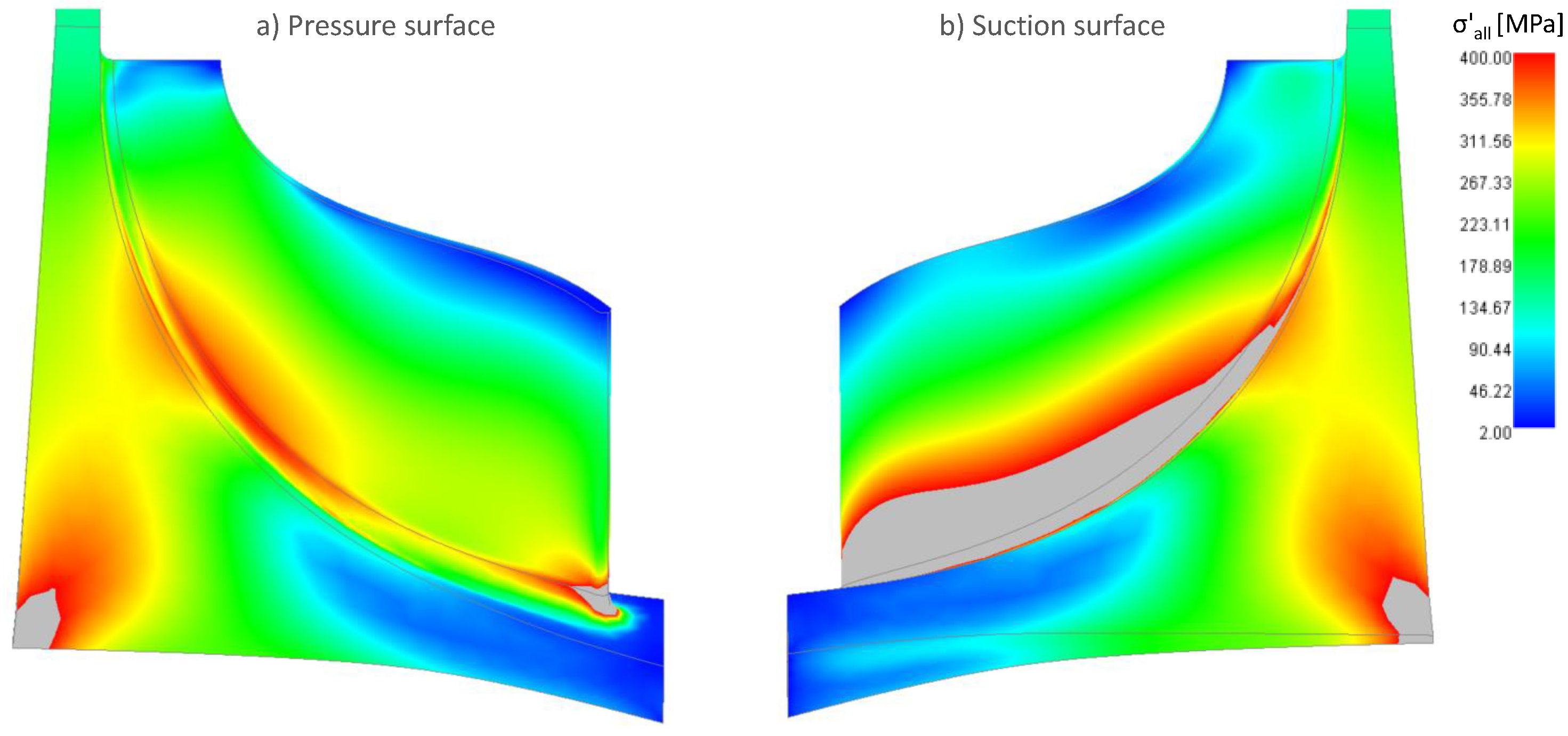
A generic Nickel-based alloy (IN 718), typically employed in gas turbine applications is used in the stress simulations of the rotor disk. Although the known materials are not used for sufficient yield strengths at temperatures exceeding 760 C [37], assumed properties are employed to investigate the range and areas of stress concentrations on a non-optimised rotor wheel design.
The static stress analysis performed signals a concern for the insufficient material strength at certain areas of the radial turbine. The aerodynamic part of the turbine itself (the designed rotor), even at higher loading than design point conditions, is mostly limited to stresses that are lower than the defined allowable von-Mises stress (400 MPa); the distribution of von Mises stresses is displayed using Figure 14. For better visualisation of the areas of high stress concentration, the contour limits of the displayed von Mises stress is set to the maximum 400 MPa; the grey regions are areas with stress over the permissible ceiling. The areas of stress concentration are defined as the disc root and the blade root both of which belong to the mechanical design aspect of the turbine. Regions of high stress reflect the need to revisit the mechanical design as part of the updated and optimised final design stage.
4. Discussion on Enabling Technologies
Several technological barriers associated to the development of turbomachinery components for sCO cycles have been identified in open literature [38]; a number of remarks can be made upon the outcomes presented in the paper based on the design of the radial turbine. The discussion to follow is rooted on information found in literature and on conversations with researchers working on related topics.
4.1. Materials Consideration
Material selection needs to be put at the forefront of the design considerations for the uncooled radial turbine for different reasons; firstly due to the creep and fatigue life, defined by material properties associated to the thermal and mechanical stresses and to the operating environment, and secondly for the synergistic effect of environment chemistry and parameters (temperature and pressure) on the material degradation. Materials have continuously evolved throughout the years to meet the high temperature operation market [39]. The proposed temperature of 900 C sits on the limit of operating temperatures that do not require cooling for turbomachinery blades; nonetheless, temperature is not the only critical limitation for the proposed work.
The required strength of material at peak temperature with the mechanical stress resulting from the loads and rotational speed, and the high thermo-physical heat transfer properties of the fluid, might dictate the use of complex single-crystal superalloys if no cooling is employed; thermal barrier coatings can be explored to enable the use of less costly materials. Wright et al. [40] show that for the temperature limit of 900 C the use of cast-alloy IN738 for turbine vanes and blades can be considered. There is a wide availability of materials, namely a range of steels, for the application in heat exchangers of state-of-the-art steam plants [41]. These cast alloys are more suitable for the turbomachinery casings, due to their high pressure capability, but not for use in the turbine blades where aero-mechanical stresses are significant.
The high inlet temperature of the turbine would dictate the use of superalloys usually employed in land based or aeroderivative gas turbines. Developments in metallurgy to reach single-crystal superalloys and coatings allow for a better creep deformation resistance in comparison to equiaxed crystal materials. Thus the extensive material database available for conventional gas and steam cycles is not appropriate for sCO applications as where a narrow selection of the high pressure- high temperature materials is limited to expensive Ni-based alloys [42].
Erosion is reported in turbines using pure supercritical CO so special attention needs to be given for erosion-resistant materials or coatings for the case of this cycle especially that the turbine operates with other contaminants coming from oxy-combustion [43]. Although short-term corrosion testing has been conducted by CSIRO for pure sCO with temperatures and pressure scales up to 1000 C and 250 bar respectively [41], results are limited because of the need to obtain more adequate long-term testing with actual conditions of impurities especially when HO is present in the working fluid. Within the same framework, increased corrosion has been reported with temperature rise; whereas the consequence of pressure change was found to be negligible. To mitigate the detrimental effect of internal oxidation and surface carburisation, the more expensive alloys with a high Chromium and Nickel content are necessitated; Austenitic steels have reduced corrosion resistance at high temperatures. Most oxidation and carburisation laboratory tests are also limited to ambient pressure environments with pure CO fluids [40].
From the information stated above, one can deduce that the current array of materials still has major testing gaps, and is not suitable for the proposed operating conditions of the turbine (900 C and 297 bar), unless cooling is incorporated. Collaborative efforts for all the material aspects is required for the actual adoption of the designed radial turbine.
4.2. Bearings
Bearings are of great design importance for the actual adaptation of the proposed radial turbine to provide support for the relative motion between the rotating parts. As the density of the fluid lowers from supercritical high density to subcritical conditions at the extreme pressure of the Allam cycle, a large axial force is generated on the turbine component; the axial thrust load issue is resolved using suitable thrust bearings [44]. Mechanical contact-type bearings such as rolling, sliding or flexing elements are not considered by researchers for sCO applications. Non contacting, fluid-film hydrodynamic bearings are suggested by some [45,46] for their prevalence in high load/high speed industrial applications. A conclusion was obtained that oil-film bearings are not suitable for supercritical CO utilisation because of the solvent-like characteristics of the sCO fluid [47]. Recommendations include a specific hybrid hydrostatically-assisted hydrodynamic gas-foil bearing design, developed by Mechanical Solutions Inc. [48], that provides both radial and thrust support in a single combination component. The maximum temperature cited is up to 650 C with a material coating which limits its applicability to the design in hand if no cooling is provided. Shaft size and weight will also limit the suitability since the inner diameter of the bearing geometry is 2 inches (≈51 mm) which is smaller than the expected shaft diameter of 120 mm (calculated for mechanical design). Another possibility is rare earth element magnetic bearings which could levitate for 100 MW shaft scales and are developed by Electron Energy Corporation [49]. In any case, because of the operating temperature and pressure ranges of the designed turbine, bearings, and other components like gears, need to be isolated from the turbine itself via shaft end seals (as discussed in the next heading). Turbomachinery design manufacturers can provide answers regarding bearing design for the configuration of the designed turbine based on shaft sizes, but it seems that commercially-ready solutions are not yet available.
4.3. Shaft End Seals
Suitable shaft end seals for sCO cycles can limit the leakage of the supercritical CO fluid to minimise cycle efficiency penalties. They are required to separate the high pressure turbine from the rest of the ancillary components. Knowing that the temperature at turbine inlet is 900 C, the seal at the end of the high-temperature/high-pressure side needs to be placed as far as possibly permissible from the turbine inlet without affecting rotordynamics. General Electric and the Southwest Research Institute [50] concluded that labyrinth seals are insufficient for providing the required low-leakage characteristics for the high-pressure fluid because the physical clearance is optimised for a single operating condition, and thus with the change of clearance gaps during different operation modes, leakage losses are aggravated. Non-contacting, dry gas lift-off face seals are suggested for high-temperature operation, with experimental testing by Sandia National Laboratories in collaboration with Flowserve Corporation at conditions of 700 C, 4400 psi (≈303 bar) and a shaft speed of 40,000 rpm [51]. In the case of the operating temperature of the modified NET Power cycle, Joule-Thomson or throttle cooling will need to be provided at that shaft end from compressor discharge to decrease the temperature to around 700 C and allow safe and effective seal operation. Commercially-ready dry gas seals are limited to shaft sizes in the range of 37.5 mm for high rotational speeds (near 50,000 rpm) and for slower speeds, they can reach up to 10 times bigger shaft diameters [45]. Looking back at the conditions of the designed turbine in terms of temperature (900 C), pressure (297 bar), rotational speed (≈20,000 rpm) and shaft diameter (≈120 mm), dry gas lift off seals are not a far measure from use for a 60–70 MW supercritical CO radial turbine.
4.4. Electrical Configuration
The turbine shaft rotational speed is in the range of 20,000 rpm which would require an appropriate choice of a step-down gearbox to speeds of 1800 rpm or 3600 rpm for coupling the turbine to a synchronous generator or for the requirement of separating the unknown speed of the compressor which is not designed yet. Not only is the selection of the gearing configuration dependant on shaft speed but also on the power scale; McClung et al. [45] report that General Electric (GE) has gearing configuration for power ratings reaching 60 MW. The availability of a gearbox providing a speed reduction from 12,000 rpm to 3600 rpm for a 50 MW turbine scale is also disclosed by Bidkar et al. [52]. Geared turbine generator sets are widely available for steam turbines with power output up to 40 MW as reported by GE and Mitsubishi Hitachi [53,54]. Gearbox manufacturers can provide information on the applicability of having a speed reduction ratio of around 6 from near 20,000 rpm for a 60–70 MW turbine.
Besides the mentioned technologies which need to be developed for successful use of the radial turbine, there are some operational design considerations reported for sCO turbines which require careful attention. Transient operation of the turbine might induce an overspeed risk and loss of electrical load due to the small size of the rotor. The necessitated temperature reduction near the turbine inlet, to safe margins tolerated by seals and bearings, incurs high thermal stresses in that region that needs addressing via further stress analysis.
5. Conclusions
This paper outlines the design procedure of a radial turbine for a cycle size of ≈100 MW starting with cycle modelling and moving towards preliminary design, performance analysis, CFD simulations, and mechanical assessment. Key findings include the identification of the areas within the turbine passage that require careful readjustment due to the presence of losses that diminish the performance. The final observation is that a radial turbine configuration is suitable for use in a utility-scale (100 MW) supercritical CO power cycle at the pressure and temperature levels of 297 bar and 900 C. The advantage of using a radial turbine is its compactness and its ability to endure a high pressure ratio in a single stage, about 5 for the designed turbine. The flow behaviour in the turbine design aligns well with results from other works on high fluid density radial turbines. However, the current design requires re-visitation to improve the overall turbine efficiency especially through optimising the design of the nozzle vanes through different stacking, or changing the number of blades to deliver better incidence to the rotor, and to reduce the exit Mach number, and thus the associated losses. The approach towards achieving the goal of employing a radial turbine in a mid-scale power plant requires further work. Future research should include, but is not limited to:
- Incorporation of the fluid mixture in the design processes to account for the influence on performance
- Optimisation of the blade profiles
- Additional stress analyses including modal, harmonic, and hot-to-cold simulations
- Experimental testing and validation
- Investigation of the relevant technologies such as seals, bearings, gearing
- Research on suitable material advancements
Author Contributions
T.E.S. performed the simulation and analysis, and drafted the manuscript. J.A.T. supervised the project, provided technical advice, and edited the manuscript. J.O. supervised the project, established research collaborations, and reviewed the manuscript. All authors have read and agreed to the published version of the manuscript.
Funding
This research received no external funding.
Acknowledgments
The authors would like to acknowledge the research group from Politecnico Di Milano that includes Prof. Paolo Chiesa, Prof. Emanuele Martelli and Roberto Scaccabarozzi for their collaboration on the cycle modelling part of the work. Also Prof. Giacomo Bruno Persico from the same institution for his input on the results of turbine design. The discussions with several researchers from the U.S. National Energy Technology Laboratory, Sandia National Laboratories, and Oak Ridge National Laboratories are highly valued. The authors appreciate the support from SoftInWay in matters relating to software.
Conflicts of Interest
The authors declare no conflict of interest.
Abbreviations
The following abbreviations are used in this manuscript:
| Roman Symbols: | |
| b | Passage width [mm] |
| c | Chord [mm] |
| M | Mach number [-] |
| Mass flow rate [kg/s] | |
| N | Number of blades [-] |
| n | Specific speed [-] |
| o | Throat [mm–m] |
| P | Pressure [bar] |
| q | Pitch [mm] |
| Volumetric flow rate [m/s] | |
| R | Degree of reaction [-] |
| r | Radius [mm] |
| s | Entropy [J/kg K] |
| T | Temperature [K– C] |
| t | Thickness [mm] |
| W | Relative velocity [m/s] |
| Power [MW] | |
| Z | Axial length [mm] |
| Greek Symbols: | |
| Absolute flow angle [] | |
| Relative flow angle [] | |
| Difference [-] | |
| Efficiency [%] | |
| Velocity ratio [-] | |
| Rotational speed [rad/s] | |
| Flow coefficient [-] | |
| Pressure ratio [-] | |
| Stage loading coefficient [-] | |
| Density [kg/m] | |
| Metal angle [] | |
| Subscripts: | |
| 0 | Total value |
| 2 | Stator inlet station |
| 3 | Stator outlet station |
| 4 | Rotor inlet station |
| 5 | Rotor outlet station |
| e | Electric |
| id | Ideal |
| m | Meanline |
| max | Maximum |
| out | Outlet |
| R | Rotor |
| rel | Relative reference frame |
| S | Stator |
| th | Thermal |
| ts | Total-to-static |
| tt | Total-to-total |
| Acronyms/Abbreviations: | |
| ASU | Air Separation Unit |
| CCS | Carbon Capture and Storage |
| CFD | Computational Fluid Dynamics |
| GE | General Electric |
| HTHE | High Temperature Heat Exchanger |
| IEA GHG | International Energy Agency GreenHouse Gas |
| LHV | Lower Heating Value |
| LTHE | Low Temperature Heat Exchanger |
| PS | Pressure Side |
| SS | Suction Side |
| TIP | Turbine Inlet Pressure |
| TIT | Turbine Inlet Temperature |
References
- Ahn, Y.; Lee, J.I. Study of Various Brayton Cycle Designs for Small Modular Sodium-Cooled Fast Reactor. Nucl. Eng. Des. 2014, 276, 128–141. [Google Scholar] [CrossRef]
- Dahlquist, A.; Genrup, M. Aerodynamic Turbine Design for an Oxy-Fuel Combined Cycle. In Proceedings of the ASME Turbo Expo 2016: Turbomachinery Technical Conference and Exposition (GT 2016), Seoul, Korea, 13–17 June 2016; Volume 2. [Google Scholar]
- Dahlquist, A.; Genrup, M.; Sjoedin, M.; Jonshagen, K. Optimization of an Oxyfuel Combined Cycle Regarding Performance and Complexity Level. In Proceedings of the ASME Turbo Expo 2013: Turbine Technical Conference and Exposition, San Antonio, TX, USA, 3–7 June 2013. [Google Scholar]
- Zhang, N.; Lior, N. Two Novel Oxy-Fuel Power Cycles Integrated with Natural Gas Reforming and CO2 Capture. Energy 2008, 33, 340–351. [Google Scholar] [CrossRef]
- Olumayegun, O.; Wang, M.; Kelsall, G. Closed-Cycle Gas Turbine for Power Generation: A State-of-the-Art Review. Fuel 2016, 180, 694–717. [Google Scholar] [CrossRef]
- Kato, Y.; Nitawaki, T.; Muto, Y. Medium Temperature Carbon Dioxide Gas Turbine Reactor. Nucl. Eng. Des. 2004, 230, 195–207. [Google Scholar] [CrossRef]
- Turchi, C.; Ma, Z.; Neises, T.W.; Wagner, M.J. Thermodynamic Study of Advanced Supercritical Carbon Dioxide Power Cycles for Concentrating Solar Power Systems. J. Sol. Energy Eng. 2013, 135, 041007. [Google Scholar] [CrossRef]
- Allam, R.; Palmer, M.; Brown, G.; Fetvedt, J.; Freed, D.; Nomoto, H.; Itoh, M.; Okita, N.; Jones, C. High Efficiency and Low Cost of Electricity Generation from Fossil Fuels while Eliminating Atmospheric Emissions, Including Carbon Dioxide. Energy Procedia 2013, 37, 1135–1149. [Google Scholar] [CrossRef] [Green Version]
- IEAGHG. Oxy-Combustion Turbine Power Plants; IEAGHG: Cheltenham, UK, 2015. [Google Scholar]
- Scaccabarozzi, R.; Gatti, M.; Martelli, E. Thermodynamic Analysis and Numerical Optimization of the NET Power Oxy-Combustion Cycle. Appl. Energy 2016, 178, 505–526. [Google Scholar] [CrossRef]
- Allam, R.; Fetvedt, J.; Forrest, B.; Freed, D. The Oxy-Fuel, Supercritical CO2 Allam Cycle: New Cycle Developments to Produce Even Lower-Cost Electricity From Fossil Fuels Without Atmospheric Emissions. In Proceedings of the ASME Turbo Expo 2014: Turbine Technical Conference and Exposition. American Society of Mechanical Engineers, Düsseldorf, Germany, 16–20 June 2014. [Google Scholar]
- Allam, R.; Martin, S.; Forrest, B.; Fetvedt, J.; Lu, X.; Freed, D.; Brown, G.; Sasaki, T.; Itoh, M.; Manning, J. Demonstration of the Allam Cycle: An Update on the Development Status of a High Efficiency Supercritical Carbon Dioxide Power Process Employing Full Carbon Capture. Energy Procedia 2017, 114, 5948–5966. [Google Scholar] [CrossRef]
- Aspen Technology Inc. Aspen Plus User Guide 10.2; Aspen Technology Inc.: Bedford, MA, USA, 2000. [Google Scholar]
- White, M.; Sayma, A. A Preliminary Comparison of Different Turbine Architectures for a 100kW Supercritical CO2 Rankine Sycle Turbine. In Proceedings of the 6th International Supercritical CO2 Power Cycles Symposium, Pittsburgh, PA, USA, 27–29 March 2018. [Google Scholar]
- Holaind, N.; Bianchi, G.; De Miol, M.; Saravi, S.; Tassou, S.; Leroux, A.; Jouhara, H. Design of Radial Turbomachinery for Supercritical CO2 Systems using Theoretical and Numerical CFD Methodologies. Energy Procedia 2017, 123, 313–320. [Google Scholar] [CrossRef]
- Zhang, H.; Zhao, H.; Deng, Q.; Feng, Z. Aerothermodynamic Design and Numerical Investigation of Supercritical Carbon Dioxide Turbine. In Proceedings of the ASME Turbo Expo 2015: Turbine Technical Conference and Exposition, Montreal, QC, Canada, 15–19 June 2015. [Google Scholar]
- Wang, Y.; Li, J.; Zhang, D.; Xie, Y. Numerical Investigation on Aerodynamic Performance of SCO2 and Air Radial-Inflow Turbines with Different Solidity Structures. Appl. Sci. 2020, 10, 2087. [Google Scholar] [CrossRef] [Green Version]
- Aungier, R. Turbine Aerodynamics Axial-Flow and Radial-Inflow Turbine Design and Analysis; ASME, Three Park Avenue: New York, NY, USA, 2006. [Google Scholar]
- Rahbar, K.; Mahmoud, S.; Al-Dadah, R. Mean-Line Modeling and CFD Analysis of a Miniature Radial Turbine for Distributed Power Generation Systems. Int. J. Low Carbon Technol. 2016, 11, 157–168. [Google Scholar] [CrossRef] [Green Version]
- Moroz, L.; Govorushchenko, Y.; Pagur, P.; Grebennik, K.; Kutrieb, W.; Kutrieb, M. Integrated Environment for Gas Turbine Preliminary Design. In Osaka International Gas Turbine Congress; Citeseer: Osaka, Japan, 2011; pp. 13–18. [Google Scholar]
- Shah, S.; Chaudhri, G.; Kulshreshtha, D.; Channiwalla, S. Radial Inflow Gas Turbine Flow Path Design. Int. J. Eng. Res. Dev. 2013, 5, 41–45. [Google Scholar]
- Aungier, R. A Fast, Accurate Real Gas Equation of State for Fluid Dynamic Analysis Applications. J. Fluids Eng. 1995, 117, 277–281. [Google Scholar] [CrossRef]
- Meijboom, L. Development of a Turbine Concept for Supercritical CO2 Power Cycles. Master’s Thesis, Delft University of Technology, Delft, The Netherlands, 2017. [Google Scholar]
- Dong, B.; Xu, G.; Luo, X.; Zhuang, L.; Quan, Y. Analysis of the Supercritical Organic Rankine Cycle and the Radial Turbine Design for High Temperature Applications. Appl. Therm. Eng. 2017, 123, 1523–1530. [Google Scholar] [CrossRef]
- Pecnik, R.; Rinaldi, E.; Colonna, P. Computational Fluid Dynamics of a Radial Compressor Operating with Supercritical CO2. J. Eng. Gas Turbines Power 2012, 134, 122301. [Google Scholar] [CrossRef]
- Wei, Z. Meanline Analysis of Radial Inflow Turbines at Design and Off-Design Conditions. Master’s Thesis, Carleton University, Ottawa, ON, Canada, 2014. [Google Scholar]
- Takagi, K.; Muto, Y.; Ishizuka, T.; Kikura, H.; Aritomi, M. Research on Flow Characteristics of Supercritical CO2 Axial Compressor Blades by CFD Analysis. In Proceedings of the 17th International Conference on Nuclear Engineering ICONE17, Brussels, Belgium, 12–16 July 2009; Volume 4, pp. 565–572. [Google Scholar]
- Horlock, J.; Torbidoni, L. Calculations of cooled turbine efficiency. J. Eng. Gas Turbines Power 2008, 130, 011703. [Google Scholar] [CrossRef]
- Wilcock, R.; Young, J.; Horlock, J. The Effect of Turbine Blade Cooling on the Cycle Efficiency of Gas Turbine Power Cycles. J. Eng. Gas Turbines Power 2005, 127, 109–120. [Google Scholar] [CrossRef]
- Fleming, D.; Holschuh, T.; Conboy, T.; Rochau, G.; Fuller, R. Scaling Considerations for a Multi-Megawatt Class Supercritical CO2 Brayton Cycle and Path Forward for Commercialization. In Proceedings of the ASME Turbo Expo 2012: Turbine Technical Conference and Exposition, Copenhagen, Denmark, 11–15 June 2012; pp. 953–960. [Google Scholar]
- Dixon, S.; Hall, C. Fluid Mechanics and Thermodynamics of Turbomachinery; Butterworth-Heinemann: Oxford, UK, 2010. [Google Scholar]
- Watch, M. Gas Turbine Market Size 2018- Global Analysis, Comprehensive Research Study, Development Status, Business Growth, Competitive Landscape, Future Plans and Trends by Forecast 2023. 2019. Available online: https://www.marketwatch.com/press-release/ (accessed on 18 December 2019).
- Cerdoun, M.; Ghenaiet, A. CFD Analyses of a Radial Inflow Turbine. In Proceedings of the 8th International Conference on Compressors and Their Systems, London, UK, 9–10 September 2013; Woodhead Publishing: Sawston, UK, 2013; pp. 635–647. [Google Scholar]
- Monteiro, V.; Zaparoli, E.; de Andrade, C.; de Lima, R. Numerical Simulation of Performance of an Axial Turbine First Stage. J. Aerosp. Technol. Manag. 2012, 4, 175–184. [Google Scholar] [CrossRef]
- Sauret, E.; Gu, Y. 3D CFD Simulations of a Candidate R143a Radial-Inflow Turbine for Geothermal Power Applications. In Proceedings of the ASME 2014 Power Conference: Turbine Technical Conference and Exposition, Düsseldorf, Germany, 16–20 June 2014. [Google Scholar]
- Baines, N. Introduction to Radial Turbine Technology; VKI Radial Turbines: Sint-Genesius-Rode, Belgium, 1992. [Google Scholar]
- Metals, H.T. Inconel 718 Technical Data. 2015. Available online: https://www.hightempmetals.com/techdata/hitempInconel718data.php (accessed on 18 December 2019).
- Brun, K.; Friedman, P.; Dennis, R. Fundamentals and Applications of Supercritical Carbon Dioxide (sCO2) Based Power Cycles; Woodhead Publishing: Sawston, UK, 2017. [Google Scholar]
- Barua, S. High-Temperature Hot Corrosion of Gas Turbine Materials. Master’s Thesis, Cranfield University, Cranfield, UK, 2018. [Google Scholar]
- Wright, I.; Pint, B.; Shingledecker, J.; Thimsen, D. Materials Considerations for Supercritical CO2 Turbine Cycles. In Proceedings of the ASME Turbo Expo 2013: Turbine Technical Conference and Exposition, San Antonio, TX, USA, 3–7 June 2013. [Google Scholar]
- Subbaraman, G.; Kung, S.; Saari, H. Materials for Supercritical CO2 Applications. In Proceedings of the 6th International Supercritical CO2 Power Cycles Symposium, Pittsburgh, PA, USA, 27–29 March 2018. [Google Scholar]
- Essilfie-Conduah, N. Operating Conditions and Materials Selection for Gas-Fired Supercritical CO2. Master’s Thesis, Cranfield University, Cranfield, UK, 2019. [Google Scholar]
- Finn, J.; He, X.; Apte, S. Erosion in Components of Supercritical CO2 Power Cycles. In Utsr Project Review Meeting; National Energy Technology Laboratory: Pittsburgh, PA, USA, 2018. [Google Scholar]
- Cho, J.; Choi, M.; Baik, Y.; Lee, G.; Ra, H.; Kim, B.; Kim, M. Development of the Turbomachinery for the Supercritical Carbon Dioxide Power Cycle. Int. J. Energy Res. 2016, 40, 587–599. [Google Scholar] [CrossRef]
- McClung, A.; Smith, N.; Allison, T.; Tom, B. Practical Considerations for the Conceptual Design of an sCO2 Cycle. In Proceedings of the 6th International Supercritical CO2 Power Cycles Symposium, Pittsburgh, PA, USA, 27–29 March 2018. [Google Scholar]
- Allison, T.; Wilkes, J.; Brun, K.; Moore, J. Turbomachinery Overview for Supercritical CO2 Power Cycles. In Proceedings of the 46th Turbomachinery and 33rd Pump Symposia, Houston, TX, USA, 12–14 December 2017; Southwest Research Institute: San Antonio, TX, USA, 2017. [Google Scholar]
- Fleming, D. Private Communication-Telephone; Sandia National Laboratories: Albuquerque, NM, USA, 2019. [Google Scholar]
- Chapman, P. Advanced Gas Foil Bearing Design for Supercritical CO2 Power Cycles. In Proceedings of the 5th International Supercritical CO2 Power Cycles Symposium, San Antonio, TX, USA, 28–31 March 2016. [Google Scholar]
- Liu, J.; Dent, P.; Palazzolo, A. Novel Ultra High Temperature Magnetic Bearings for Space Vehicle Systems; Technical Report; Electron Energy Corporation: Landisville, PA, USA, 2018. [Google Scholar]
- Bidkar, R.; Sevincer, E.; Wang, J.; Thatte, A.; Mann, A.; Peter, M.; Musgrove, G.; Allison, T.; Moore, J. Low-Leakage Shaft-End Seals for Utility-Scale Supercritical CO2 Turboexpanders. J. Eng. Gas Turbines Power 2016, 139, 022503. [Google Scholar] [CrossRef] [Green Version]
- Fleming, D. Experience with < 1MW Supercritical Power Generation Technology Development; Technical Report; Sandia National Laboratories: Albuquerque, NM, USA, 2017. [Google Scholar]
- Bidkar, R.; Mann, A.; Singh, R.; Sevincer, E.; Cich, S.; Day, M.; Kulhanek, C.; Thatte, A.; Peter, A.; Hofer, D.; et al. Conceptual Designs of 50 MWe and 450 MWe Supercritical CO2 Turbomachinery Trains for Power Generation from Coal. Part 1: Cycle and Turbine. In Proceedings of the 5th International Symposium—Supercritical CO2 Power Cycles, San Antonio, TX, USA, 28–31 March 2016. [Google Scholar]
- Systems, G.P. Steam Turbines for Industrial Applications. Available online: https://www.ge.com/content/dam/gepower-pgdp/global/en_US/documents/technical/ger/ger-3706d-steam-turbines-industrial-applications.pdf (accessed on 1 March 2020).
- Systems, M.H.P. Geared Turbines. Available online: https://www.mhps.com/products/steamturbines/lineup/industrial/deceleration/ (accessed on 18 March 2020).
Figure 1.
Overall methodology flowchart.

Figure 2.
Preliminary design space: (a) Flow coefficient vs velocity ratio, (b) Power vs velocity ratio.
Figure 2.
Preliminary design space: (a) Flow coefficient vs velocity ratio, (b) Power vs velocity ratio.
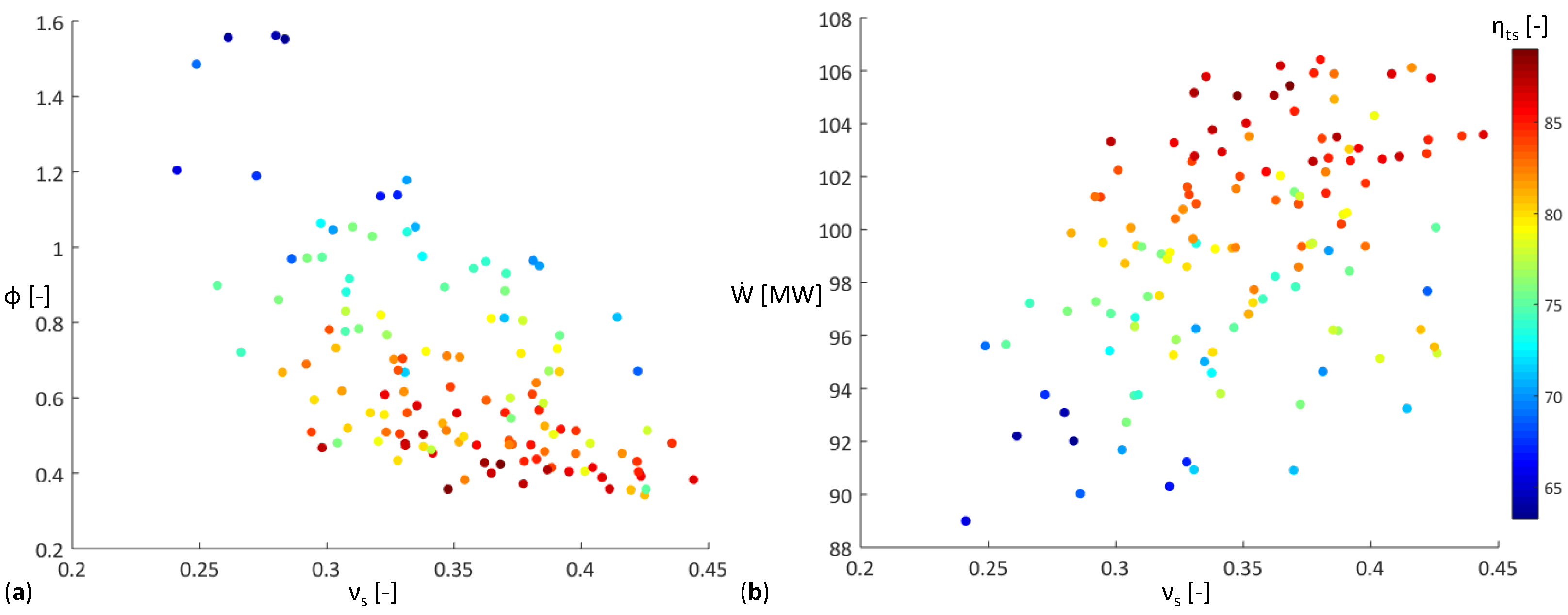
Figure 3.
3D model of selected turbine: (a) Front view, (b) Perspective view.
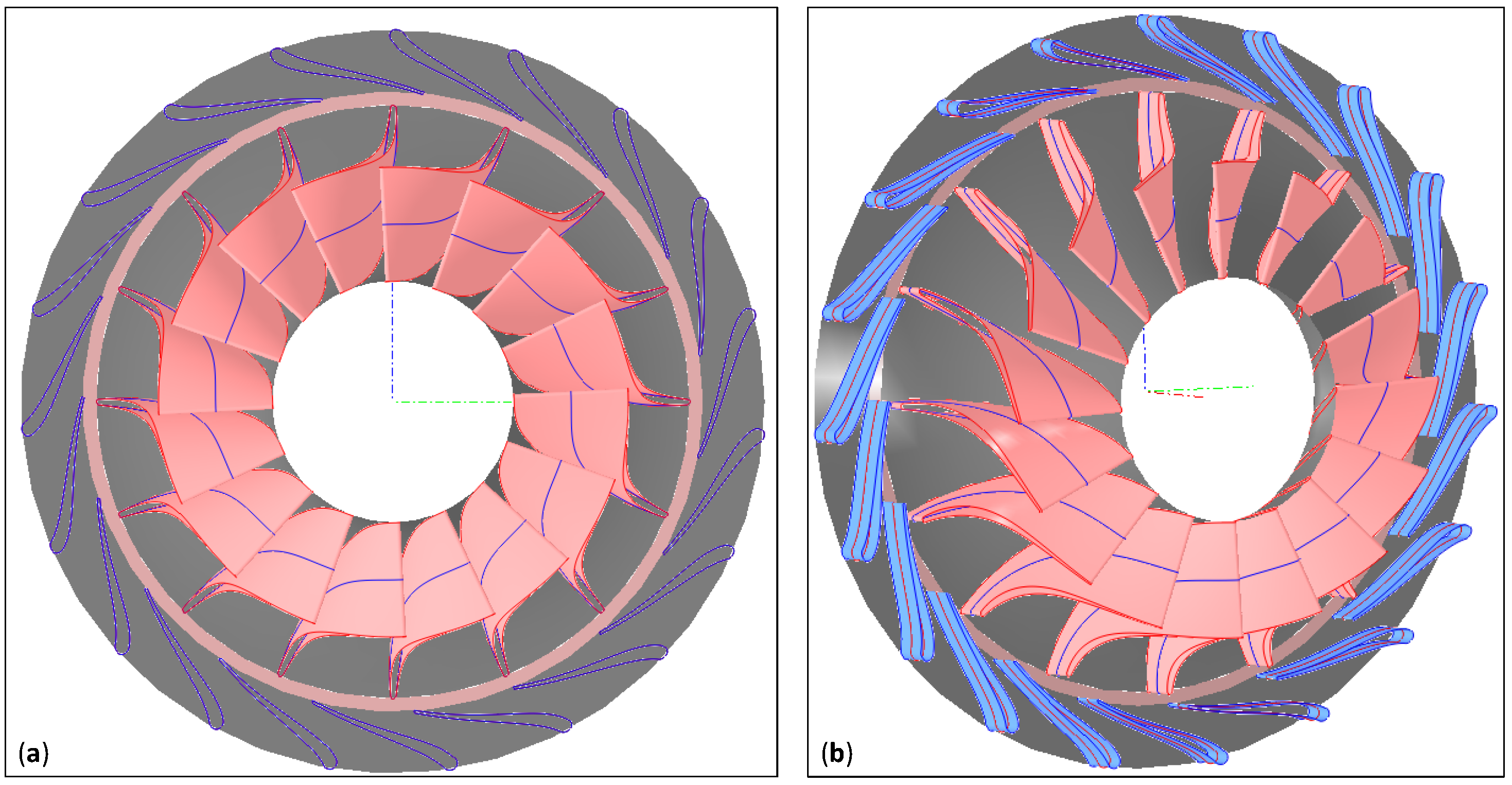
Figure 4.
Meridional dimensions of selected turbine.
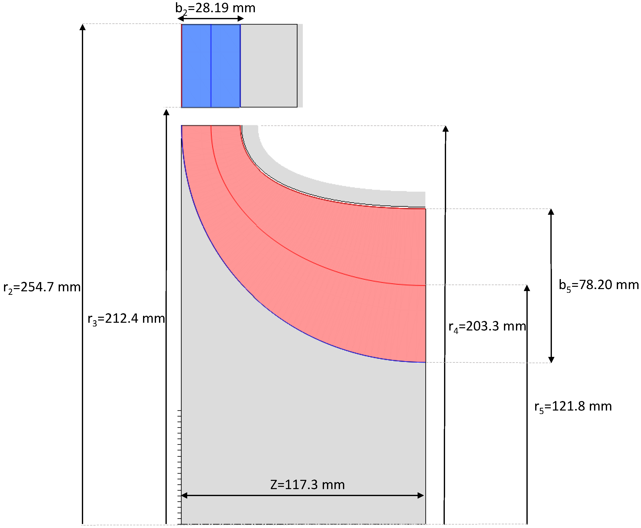
Figure 5.
Relative Mach number distribution at three spanwise turbine passage locations: (a) 10% span, (b) 50% span, (c) 90% span.
Figure 5.
Relative Mach number distribution at three spanwise turbine passage locations: (a) 10% span, (b) 50% span, (c) 90% span.
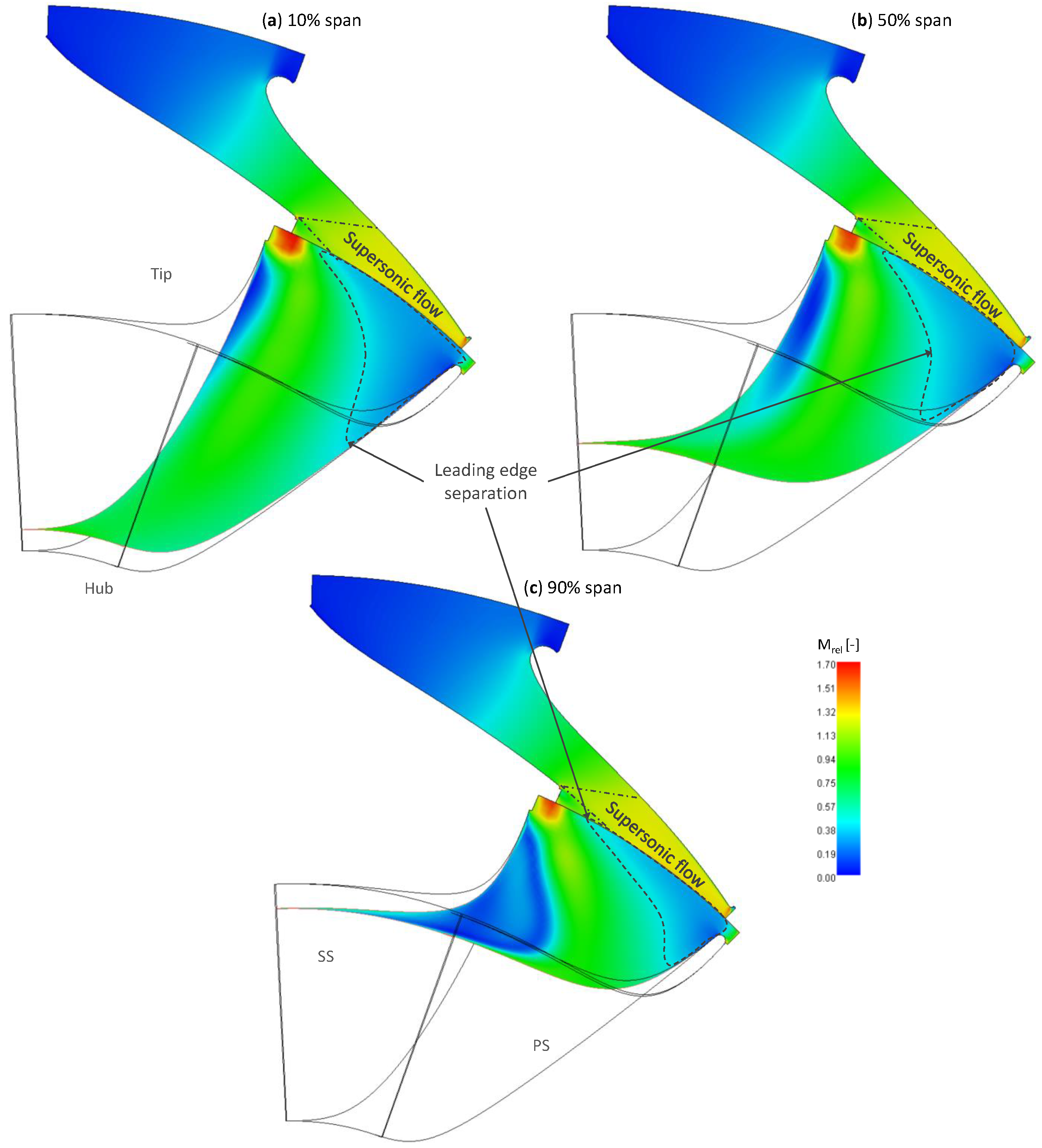
Figure 6.
Relative velocity contour at three spansiwse rotor passage locations: (a) 10% span, (b) 50% span, (c) 90% span.
Figure 6.
Relative velocity contour at three spansiwse rotor passage locations: (a) 10% span, (b) 50% span, (c) 90% span.
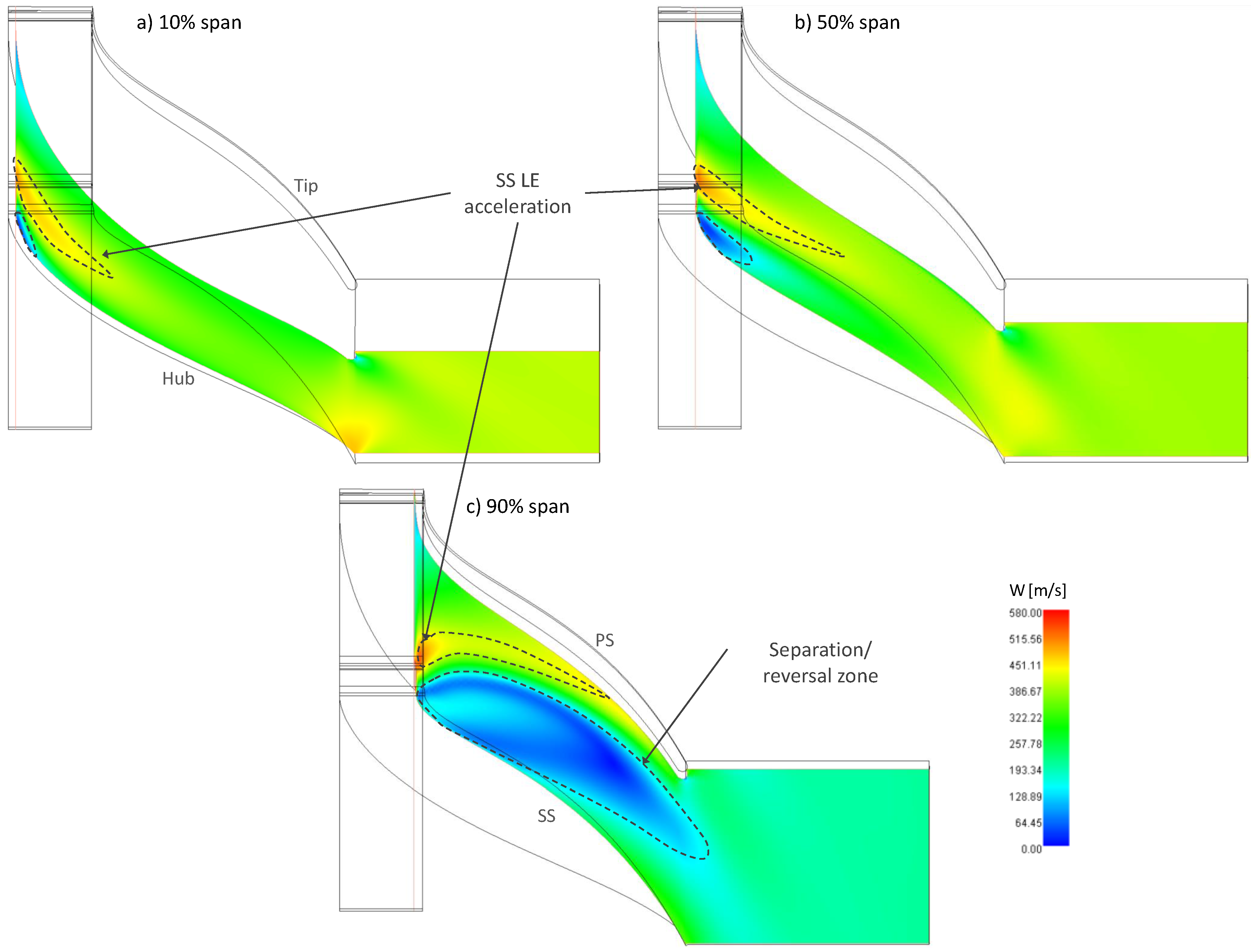
Figure 7.
Entropy contours at three spanwise rotor passage locations: (a) 10% span, (b) 50% span, (c) 90% span.
Figure 7.
Entropy contours at three spanwise rotor passage locations: (a) 10% span, (b) 50% span, (c) 90% span.

Figure 8.
(A) Domain stream definition, (B) Relative rotor pressure distribution in rotor stream-sections, flowing downstream: (a) R1, (b) R2, (c) R3, (c) R4.
Figure 8.
(A) Domain stream definition, (B) Relative rotor pressure distribution in rotor stream-sections, flowing downstream: (a) R1, (b) R2, (c) R3, (c) R4.
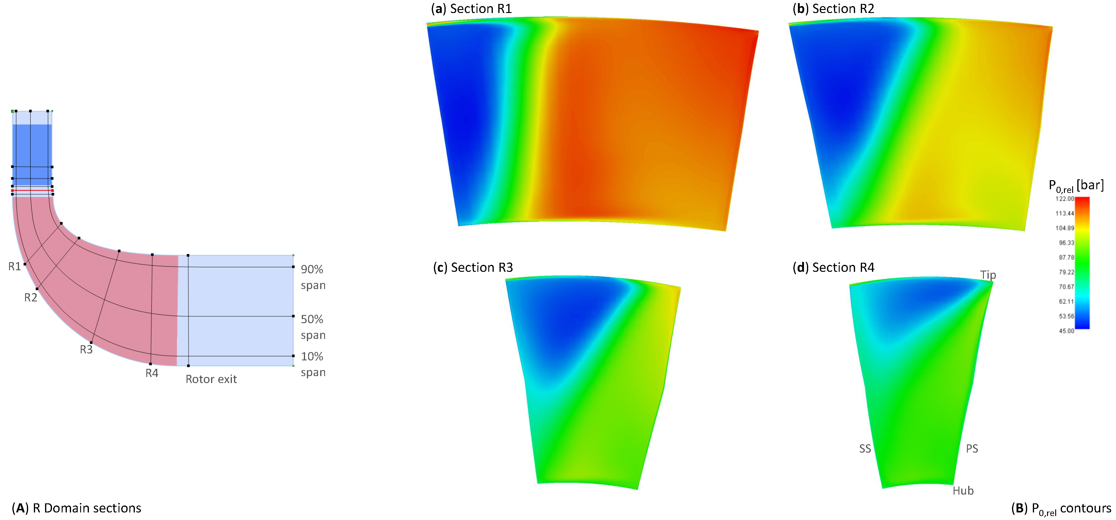
Figure 9.
Relative total pressure contours at rotor exit stream section.
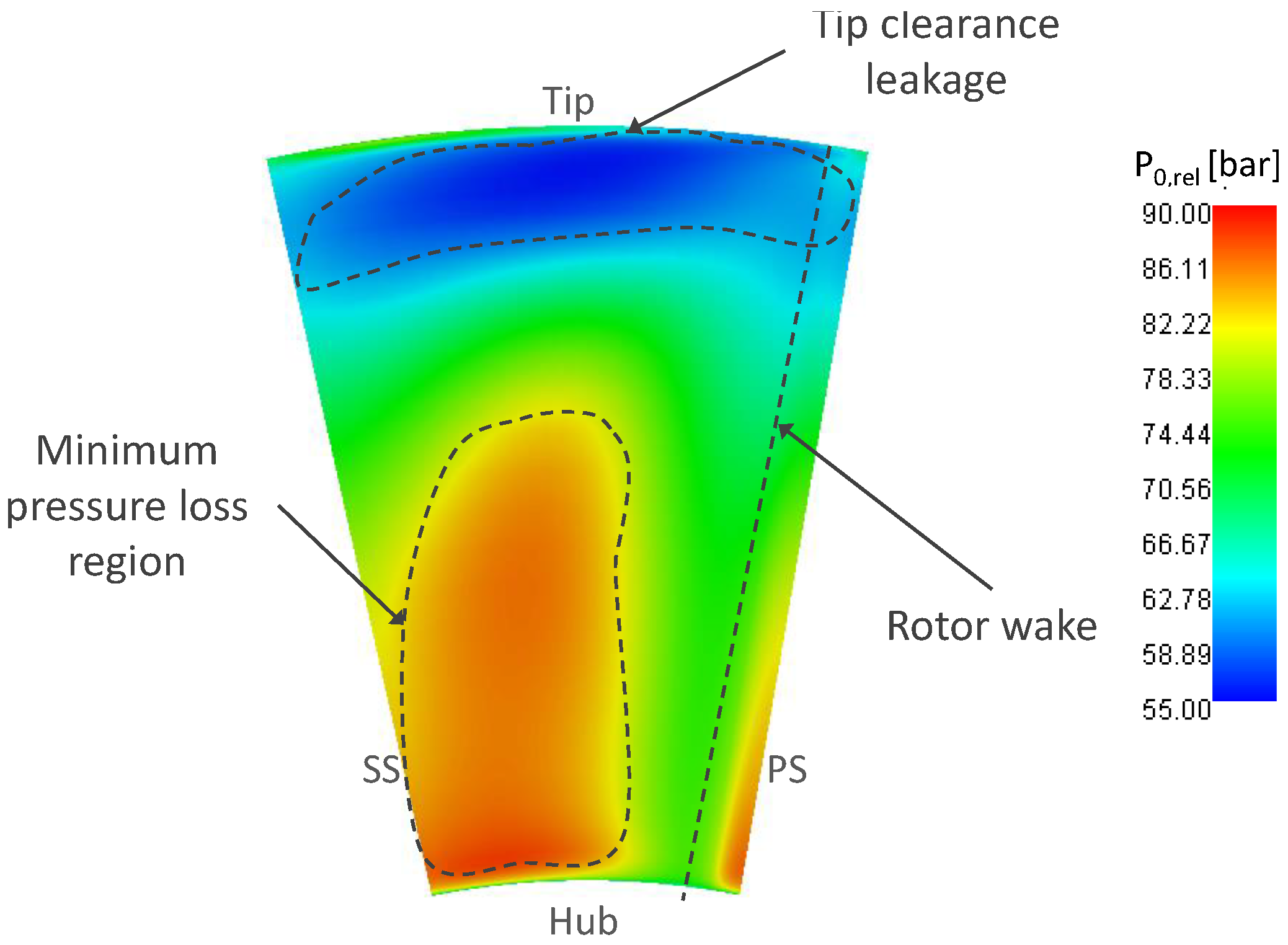
Figure 10.
Variation of parameters with total-to-static pressure ratio at three rotational speeds: (a) Mass flow, (b) Stator outlet Mach number.
Figure 10.
Variation of parameters with total-to-static pressure ratio at three rotational speeds: (a) Mass flow, (b) Stator outlet Mach number.

Figure 11.
Variation of efficiencies with total-to-static pressure ratio at three rotational speeds: (a) Total-to-total efficiency, (b) Total-to-static efficiency.
Figure 11.
Variation of efficiencies with total-to-static pressure ratio at three rotational speeds: (a) Total-to-total efficiency, (b) Total-to-static efficiency.

Figure 12.
Off-design relative Mach number distribution at mid-span from 3D CFD simulations: (a) 23,550 rpm & = 3, (b) 19,268 rpm & = 7.
Figure 12.
Off-design relative Mach number distribution at mid-span from 3D CFD simulations: (a) 23,550 rpm & = 3, (b) 19,268 rpm & = 7.

Figure 13.
Mid-span parameters distribution for isolated rotor 3D CFD model.

Figure 14.
Von-Mises stress distribution on rotor blade surfaces: (a) Pressure surface, (b) Suction surface.
Figure 14.
Von-Mises stress distribution on rotor blade surfaces: (a) Pressure surface, (b) Suction surface.

Table 1.
Design space explorer constraints.
| Parameter | Unit | Constraint |
|---|---|---|
| Power | MW | ≥ from cycle Section 3.1 |
| Efficiency | % | ≥80 |
| Flow coefficient | - | <1 |
| Rotor inlet blade speed | m/s | ≈450 |
| Rotor outlet absolute flow angle | ≈0 |
Table 2.
Comparison of optimised cycle between [10] and uncooled turbine model.
Table 2.
Comparison of optimised cycle between [10] and uncooled turbine model.
| Unit | Results of This Work | Results of [10] Optimised Cycle | |
|---|---|---|---|
| Thermal energy of feedstock (LHV) | MW | 768.21 | 768.31 |
| Turbine power output | MW | 610.55 | 609.74 |
| Recycle flow compressors | MW | 88.00 | 97.81 |
| Natural gas compressor | MW | 3.97 | - |
| Air separation unit | MW | 85.51 | - |
| Storage compressor | MW | 0.25 | - |
| Net electric power output | MW | 432.82 | 421.06 |
| Turbine outlet temperature | C | 830.53 | 783.81 |
| Turbine inlet flow rate | kg/s | 1567.7 | 1513.7 |
| Net electric efficiency (LHV) | % | 56.34 | 54.80 |
Table 3.
Modified cycle performance parameters.
| Data | Unit | Value |
|---|---|---|
| HTHE heat duty | MW | 242.92 |
| LTHE heat duty | MW | 43.42 |
| Thermal energy of feedstock (LHV) | MW | 137.18 |
| Turbine power output | MW | 99.31 |
| Vapor phase compressors | MW | 3.96 |
| Dense phase compressors | MW | 8.86 |
| Oxidant compressor | MW | 3.09 |
| Total flow compressors | MW | 15.91 |
| Natural gas compressor | MW | 0.74 |
| Air separation unit | MW | 15.29 |
| Storage compressor | MW | 0.045 |
| Net electric power output | MW | 67.33 |
| Net electric efficiency (LHV) | % | 49.08 |
Table 4.
Radial turbine boundary conditions from cycle model.
| Data | Unit | Value |
|---|---|---|
| Inlet temperature (T) | C | 900 |
| Inlet pressure (P) | bar | 297 |
| Mass flow rate | kg/s | 354.2 |
| Outlet pressure | bar | 60 |
| Thermal power output () | MW | 100.7 |
| Fluid Component Mole Fractions | ||
| CO | % | 94.06 |
| HO | % | 4.13 |
| N | % | 1.14 |
| Ar | % | 0.55 |
| O | % | 0.12 |
Table 5.
Input data for preliminary turbine design.
| Variable | Unit | Value |
|---|---|---|
| Boundary Conditions | ||
| Inlet total pressure | bar | 297 |
| Inlet total temperature | K | 1173 |
| Outlet total pressure | bar | 60 |
| Mass flow rate | kg/s | 354.2 |
| Inlet rotor metal angle | 90 | |
| Shaft rotational speed | rpm | 17,000–24,000 |
| Geometric Parameters and Constraints | ||
| Stator outlet mean diameter | m | 0.4–0.6 |
| Rotor blade height ratio | - | 2–3 |
| Rotor diameter ratio | - | 1.5–3 |
| Rotor inlet height | m | 0.01–0.04 |
| Hub reaction | - | 0.3–0.5 |
| Stator inlet diameter | m | 0.4–0.8 |
| Inlet flow angle | 1–179 | |
| Rotor outlet hub diameter | m | 0.05–0.3 |
Table 6.
Geometric parameters of turbine stator () and rotor () blades.
| Stator | Rotor | ||||
|---|---|---|---|---|---|
| Variable | Unit | Value | Data | Unit | Value |
| Blade count (N) | - | 19 | N | - | 16 |
| Chord (c) | mm | 99.90 | c | mm | 176.0 |
| Pitch (q) | mm | 70.24 | q | mm | 47.81 |
| Inlet thickness (t) | mm | 9.150 | t | mm | 3.520 |
| Outlet thickness (t) | mm | 1.830 | t | mm | 3.520 |
| Throat (o) | mm | 16.82 | o | mm | 28.35 |
| Inlet angle () | 112.42 | 90 | |||
| Outlet angle () | 13.86 | 36.37 | |||
Table 7.
Anticipated performance results.
| Variable | Unit | Value |
|---|---|---|
| kg/s | 354.6 | |
| MW | 101.6 | |
| Total-to-total efficiency () | % | 88.25 |
| Total-to-static efficiency () | % | 83.40 |
| - | 0.344 | |
| Stage loading () | - | 1.42 |
| - | 0.433 | |
| Degree of reaction (R) | - | 0.282 |
| - | 5.52 |
Table 8.
Performance results for 3D CFD mesh sensitivity study using two different boundary condition definitions.
Table 8.
Performance results for 3D CFD mesh sensitivity study using two different boundary condition definitions.
| Boundary Condition: & P | ||||
|---|---|---|---|---|
| Number of Elements [-] | P [bar] | [MW] | [%] | [%] |
| 51,110 | 224 | 83.97 | 72.66 | 67.50 |
| 209,308 | 281 | 93.16 | 73.48 | 67.98 |
| 971,613 | 282 | 102.2 | 69.77 | 63.17 |
| Boundary Condition: P & P | ||||
| Number of Elements [-] | [kg/s] | [MW] | [%] | [%] |
| 51,110 | 377.3 | 81.48 | 76.28 | 70.42 |
| 209,308 | 375.2 | 101.3 | 73.01 | 67.21 |
| 971,613 | 372.5 | 108.5 | 69.87 | 63.05 |
Table 9.
3D CFD performance results.
| Variable | Unit | Value |
|---|---|---|
| kg/s | 372.5 | |
| MW | 108.5 | |
| % | 69.87 | |
| % | 63.05 | |
| - | 1.34 | |
| - | 0.511 | |
| R | - | 0.355 |
| - | 5.51 |
Table 10.
Variation of relative flow angle at rotor inlet and absolute flow angle at rotor outlet at off-design conditions.
Table 10.
Variation of relative flow angle at rotor inlet and absolute flow angle at rotor outlet at off-design conditions.
| 2 | 3 | 4 | 5 | 6 | 7 | |
|---|---|---|---|---|---|---|
| [] | ||||||
| 19,268 rpm | −1.07 | 43.97 | 49.88 | 51.10 | 51.28 | 51.25 |
| 21,409 rpm | −37.01 | −44.19 | 40.92 | 44.21 | 45.29 | 45.65 |
| 23,550 rpm | −58.45 | 0.47 | 26.21 | 33.57 | 36.22 | 37.29 |
| [] | ||||||
| 19,268 rpm | 56.5 | 36.8 | 15.95 | 0.02 | −10.64 | −17.22 |
| 21,409 rpm | 63.06 | −27.85 | 26.09 | 9.56 | −2.35 | −10.27 |
| 23,550 rpm | 69.81 | 48.48 | 34.49 | 18.65 | 5.87 | −3.04 |
Table 11.
3D CFD performance results for the isolated rotor.
| Variable | Unit | Value |
|---|---|---|
| kg/s | 356.3 | |
| MW | 86.38 | |
| % | 87.80 | |
| % | 80.46 | |
| - | 1.21 | |
| - | 0.423 | |
| R | - | 0.406 |
| - | 4.75 |
© 2020 by the authors. Licensee MDPI, Basel, Switzerland. This article is an open access article distributed under the terms and conditions of the Creative Commons Attribution (CC BY) license (http://creativecommons.org/licenses/by/4.0/).
Share and Cite
MDPI and ACS Style
El Samad, T.; Amaral Teixeira, J.; Oakey, J. Investigation of a Radial Turbine Design for a Utility-Scale Supercritical CO2 Power Cycle. Appl. Sci. 2020, 10, 4168. https://doi.org/10.3390/app10124168
AMA Style
El Samad T, Amaral Teixeira J, Oakey J. Investigation of a Radial Turbine Design for a Utility-Scale Supercritical CO2 Power Cycle. Applied Sciences. 2020; 10(12):4168. https://doi.org/10.3390/app10124168
Chicago/Turabian StyleEl Samad, Tala, Joao Amaral Teixeira, and John Oakey. 2020. "Investigation of a Radial Turbine Design for a Utility-Scale Supercritical CO2 Power Cycle" Applied Sciences 10, no. 12: 4168. https://doi.org/10.3390/app10124168
Note that from the first issue of 2016, this journal uses article numbers instead of page numbers. See further details here.