1. Introduction
From a geotechnical perspective, engineering soils consist of the natural accumulation of mechanically separable mineral particles [
1], occurring with varying thicknesses. From a geomorphological perspective, they are produced by the weathering and sedimentation of unaltered bedrock, and occur at shallow depths. The geotechnical approach determines the engineering soils behaviour from its mechanical properties, when loads are applied by human structures, or by dynamics from its intrinsic properties in the natural environment [
2].
Different human activities are distributed geographically and depend on social, economic and environmental criteria, and geotechnical parameters are rarely considered during the first phases of territorial planning for soil use. This phenomenon is particularly important for natural parks, which comprise important resources (landscape, geology, fauna and vegetation as well as archaeological deposits). These spaces must be promoted as environmentally important through the construction of different facilities, such as classrooms in natural parks, bridges, didactic pathways; additional constructions for traditional soil uses; and the promotion of sustainable activities (agriculture and livestock). Urban development in these sectors, which are naturally fragile, must necessarily consider the geotechnical character of the different sectors in the territory.
The aim of this paper, is to prepare a set of engineering geology maps primarily to guide decision making on planning and management of two natural protected areas but also so that necessary urban and infrastructure development can be carried out with fewer impacts on fragile environments as well as reducing hazards and damage to constructions with consequent savings to society and the economy.
Engineering geology mapping includes basic previously derived information for urban development decision making in a territory, and it can facilitate important socioeconomic savings if a priori decisions consider the area’s natural hazards and spatial distribution. It is necessary to understand the resistance and deformability of each geological material as well as the geomechanical behaviours on a short-to-medium timescale to establish a priori the potential natural risks from physical maps (geomorphology, hydrology-hydrogeology, lithology and geotechnic).
The precedent in Spain for geotechnical mapping began in the 1970s [
3,
4,
5,
6,
7] and comprised geotechnical zoning by describing the following factors: bedrock lithology, superficial formations, geomorphology and hydrology/hydrogeology. In addition, geotechnical mapping includes the geotechnical conditions for each territorial sector, including the physical and mechanical characteristics of the soils and rock massifs. These maps, which were scaled at 1:200,000, were used to analyse the aptitude for numerous civil engineering projects because they included aspects such as topography, morphology, seismicity, lithological competence, mechanical properties, groundwater levels, vegetation, soil uses and climatology. The methodology followed in this mapping was promoted by UNESCO in Europe [
8]. Later, in the 1990s, geotechnical mapping was developed and included natural hazards for certain cities wherein urban development growth was notable; these maps were at a 1:25,000 scale and, in some sectors, a 1:5,000 scale [
9]. Worldwide, geotechnical cartographies have been applied to natural risks in large cities and regions [
10,
11,
12,
13,
14] or for certain infrastructures or movements in the area [
15,
16,
17].
The geographic information system (GIS) that includes geotechnical mapping considers many natural variables that are applied to planning urban areas and most wide territorial sectors [
18,
19,
20].
Herein, a methodological cartographic procedure is established that facilitates geotechnical characterisation of a region, which different administrations (national, regional government and/or municipal) use in the first phases of planning region. This procedure includes zoning that spatially differentiates and distributes the geological and geomorphologic factors with constructive incident, that can be attributed especially to the lithology, geomorphologic domains, hydrogeological units and geotechnical properties. In addition, this geotechnical, basic and preliminary characterisation facilitates estimation of the foundation conditions and typology as well as analysis and geotechnical classification of the soils in each territorial sector. This characterisation complements analysis of the physical environment on having integrated the different susceptibilities (lithological and hydrogeological, among others) that affect the geotechnical aspects. Without this characterisation, studies and geotechnical reports may not be fully used for each constructive typology considered for development. Further, the geotechnical mapping will aid in establishing the natural associated dangers or potential risks for each zone, which will preserve constructive activities in the above sectors or establish the appropriate structural measurements for different infrastructures (building houses, road construction and recreation areas, among others).
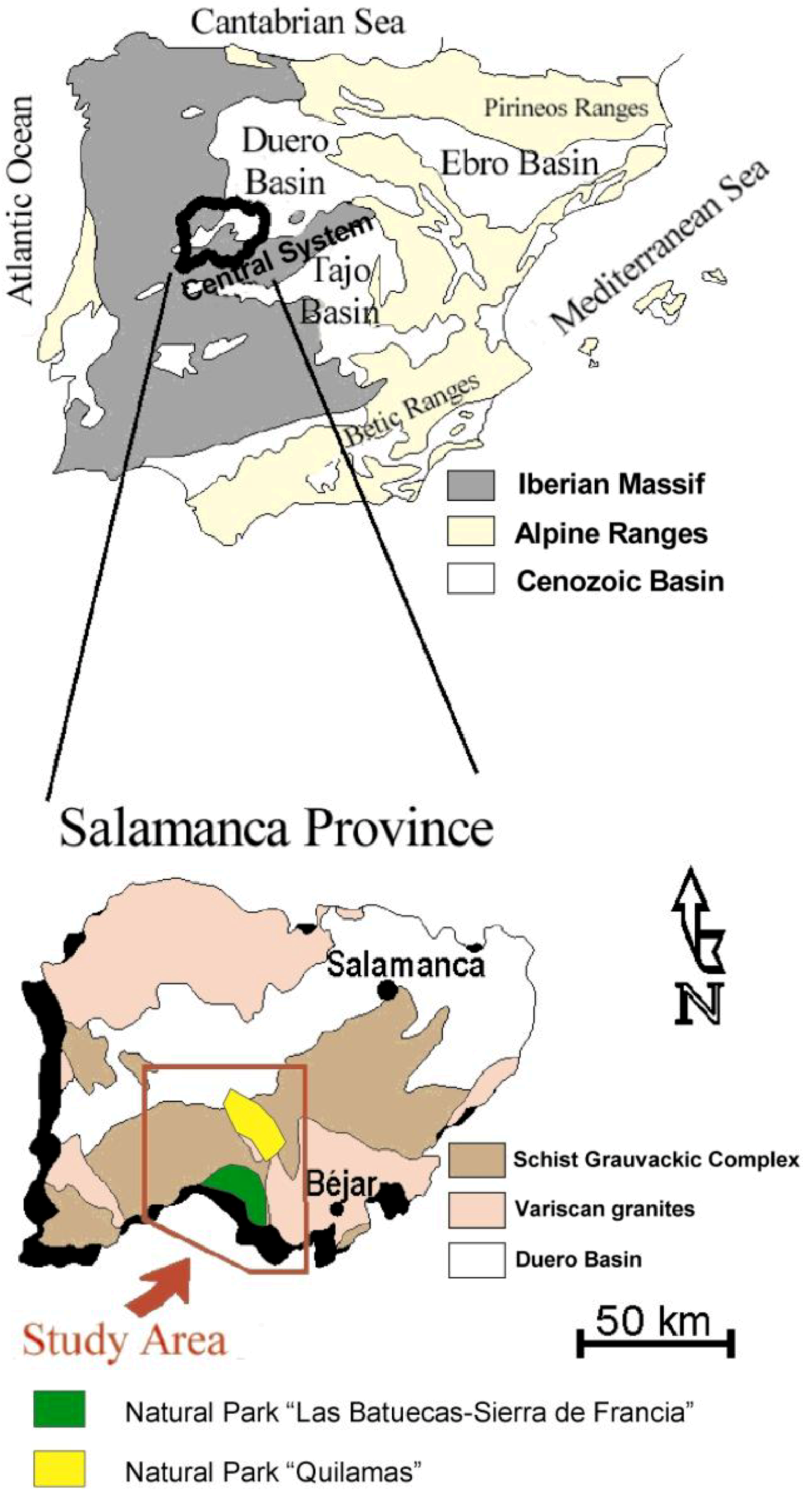
To verify and to validate this cartographic procedure, it was applied to two natural protected parks, “Las Batuecas-Sierra de Francia” and “Quilamas”, which are located in the spurs of the Central Spanish System south of the Autonomous Community of Castile and León and the province of Salamanca (
Figure 1). Nevertheless, though validation of this methodology was successful using these two natural parks, the methodology is global and applicable to any natural space. This methodology is different from other existing methodologies because it details certain factors with greater precision. Thus, for example morphological mapping in the geotechnical maps published in Spain is performed at 1:200,000, whereas here the geomorphological analysis and the synthetic mapping of geomorphological domains are performed at a working scale of 1:10,000 and 1:18,000, and are presented at a scale of 1:50,000 with the other maps. The structural and slope factors were obtained with greater precision since we were working with a digital terrain model created from a grid of individual geodesic reference points and level curves at a scale of 1:10,000. This enhanced precision is a result of the implementation of GIS technologies (mapping of slopes from the digital terrain model, and the mapping of alignments and fractures) and the elaboration of a natural hazards map based on the interactions among the factors analyzed, and it offers a non-structural measure to protect these sectors from potential uses that promote instability in the area, and which are so discontinuous and random that they pass unnoticed. The non-structural measures are hazard mitigation measures, which do not involve engineering work, and are good prevention tools that may include legislation, planning strategies, or thematic maps, such as that reported here. These measures allow certain hazards to be defined and prevented in the early steps of the spatial planning of different projects, affording alternatives for correct emplacement without the need for structural measures involving civil engineering. The “Las Batuecas-Sierra de Francia” natural park comprises a 32,300 ha surface in a zone with a socioeconomic influence affecting 44,800 ha. The number of visitors in 2009 was 38,518. The “Quilamas” natural park comprises an 11,100 ha surface. These natural protected parks form part of the Central Spanish System in the Iberian Massif. Lithologically, they comprise metasedimentary materials from the schist-greywacke complex from the Upper Vendiense to Lower Cambrian, materials from the Ordovician and Devonian (Armorican quartzites, grey and black slates), and the granitic outcrops and Neogene sediments that have formed the foothills of the saws.
Figure 1.
Study area: Protected natural park “Las Batuecas-Sierra de Francia” and “Quilamas”.
Figure 1.
Study area: Protected natural park “Las Batuecas-Sierra de Francia” and “Quilamas”.
2. Methods
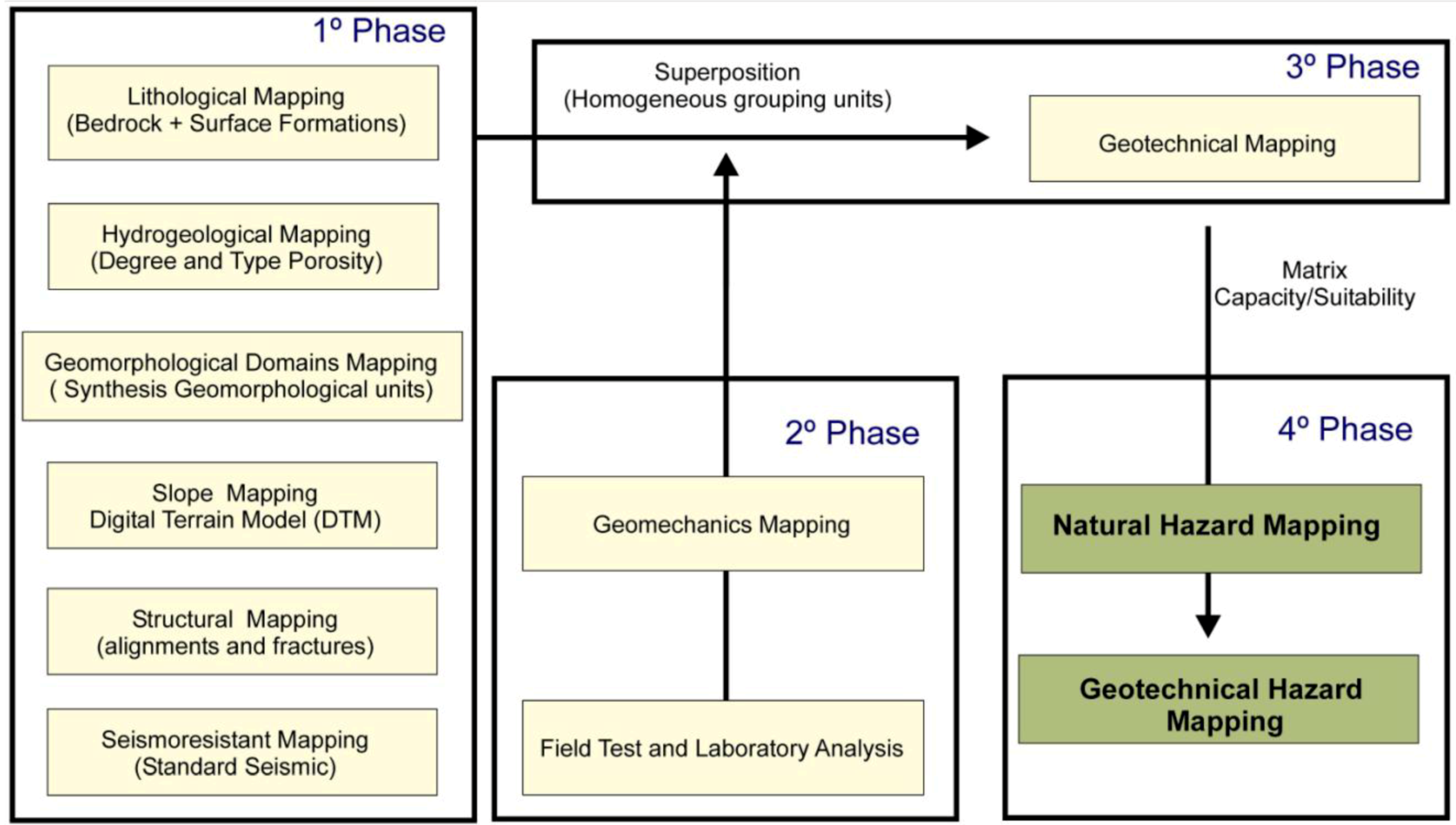
In the first phase (
Figure 2), the basic cartographies are known, including the lithological (bedrock and superficial formations), hydrogeological and geomorphologic (geomorphologic units) cartographies from aerial photographs and field campaigns. Next, certain cartographies at a 1:50,000 scale are synthesised to overlap the different maps and facilitate a manageable number of categories for zoning the area of study; in this form, the geomorphologic unit mapping has been simplified to geomorphologic domains cartography.
The spatial information that corresponds to the digital topographic database (vector format) on a 1:10,000 scale aids in the generation of a digital model terrain using GIS technologies, ArcGIS version 10. This digital model terrain comprises marked points as well as level curves and more accurately delimits certain geomorphologic domains (controls) using slope mapping (format grid). Using the extensions for the GIS ArcGIS version 10: Spatial Analyst and 3D Analyst, we generated a reliable, shaded model that facilitates analysis of the limits for adding existing fractures, which were produced using digitalization and obtained from other cartographies published and observed in the field. The territorial sectors near these zones comprising weakness and/or breaks were increasingly susceptible to risk, and danger, and they determine the instability for the area. Finally, the mapping considered seismoresistance because seismic risk is a factor in activation of instabilities.
Figure 2.
Methodological scheme for the production of the natural hazard cartography and geotechnical hazard cartography.
Figure 2.
Methodological scheme for the production of the natural hazard cartography and geotechnical hazard cartography.
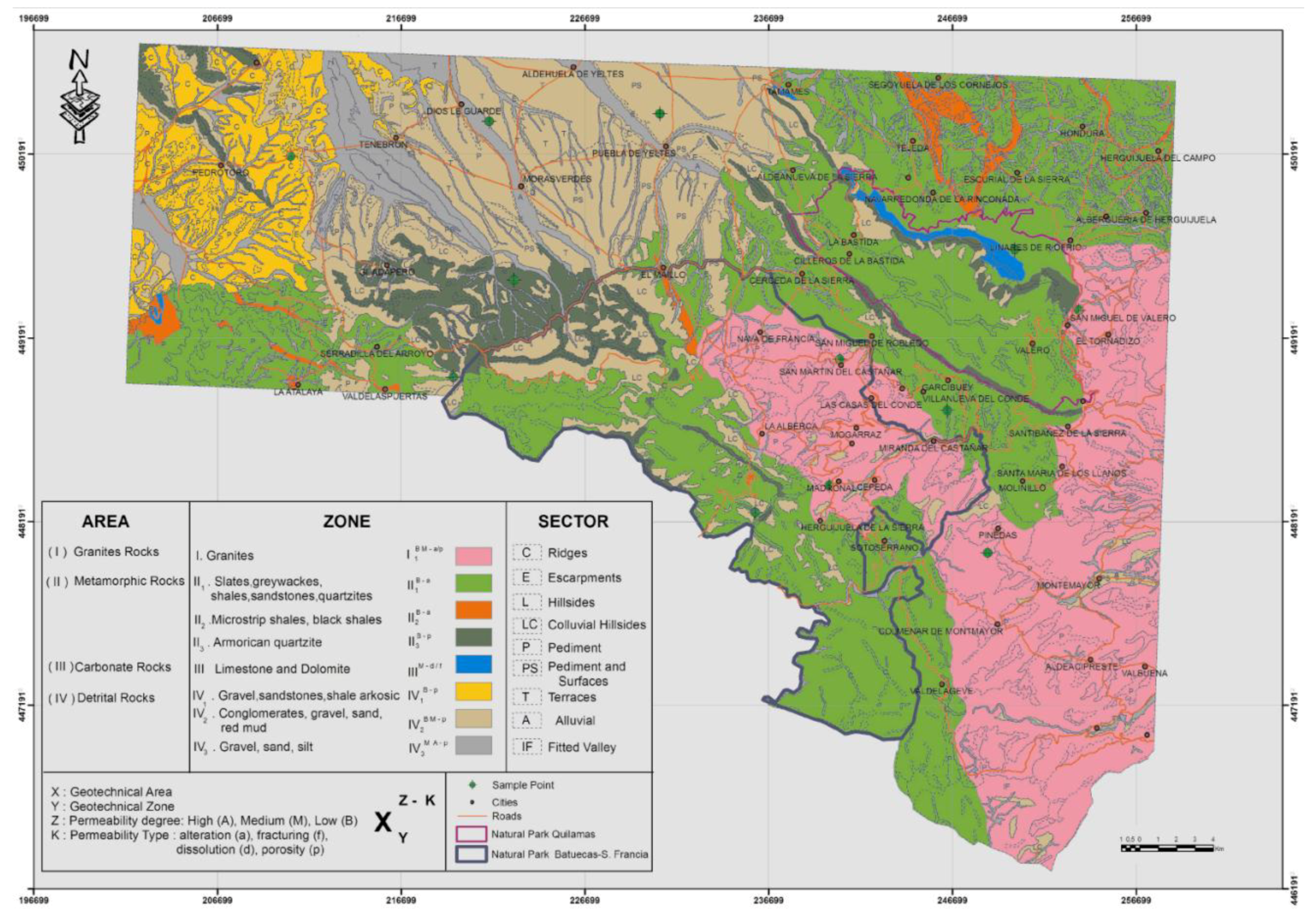
To generate the lithological mapping, we grouped the materials by related characteristics such as composition and geomechanical behaviour. Further, we differentiated two large lithological groups, the bedrock and superficial formations. To represent the bedrock, the geological national map (1:50,000) is used as the base, and the materials are grouped in broader categories such as composition and geomechanical properties, which creates homogeneous areas. The surficial deposits (Quaternary deposits) were mapped in their entirety, given the small amount of existing information in the official geological cartographies.
This method generates the first area division on the basis of different lithological groups. These areas were assigned with roman numbers: area I, granites; area II, metamorphic rocks; area III, carbonate rocks; and area IV, detritic rocks. Next, the lithology for each area or group differs, and considering these characteristics and compositional variations, the differences for the lithological II area that correspond to metamorphic rocks include the following three types of materials: II
1 slates, schists, graywackes and sandstones; II
2 black and micro-striped slates; and II
3 armorican quartzites. In the lithological area from detritic rocks IV, the following three materials differ: IV
1 arkosic conglomerates, sands and muds; IV
2 reddish-colour conglomerates, sands and mires; and IV
3 alluvial floor gravels and sands (
Figure 3a).
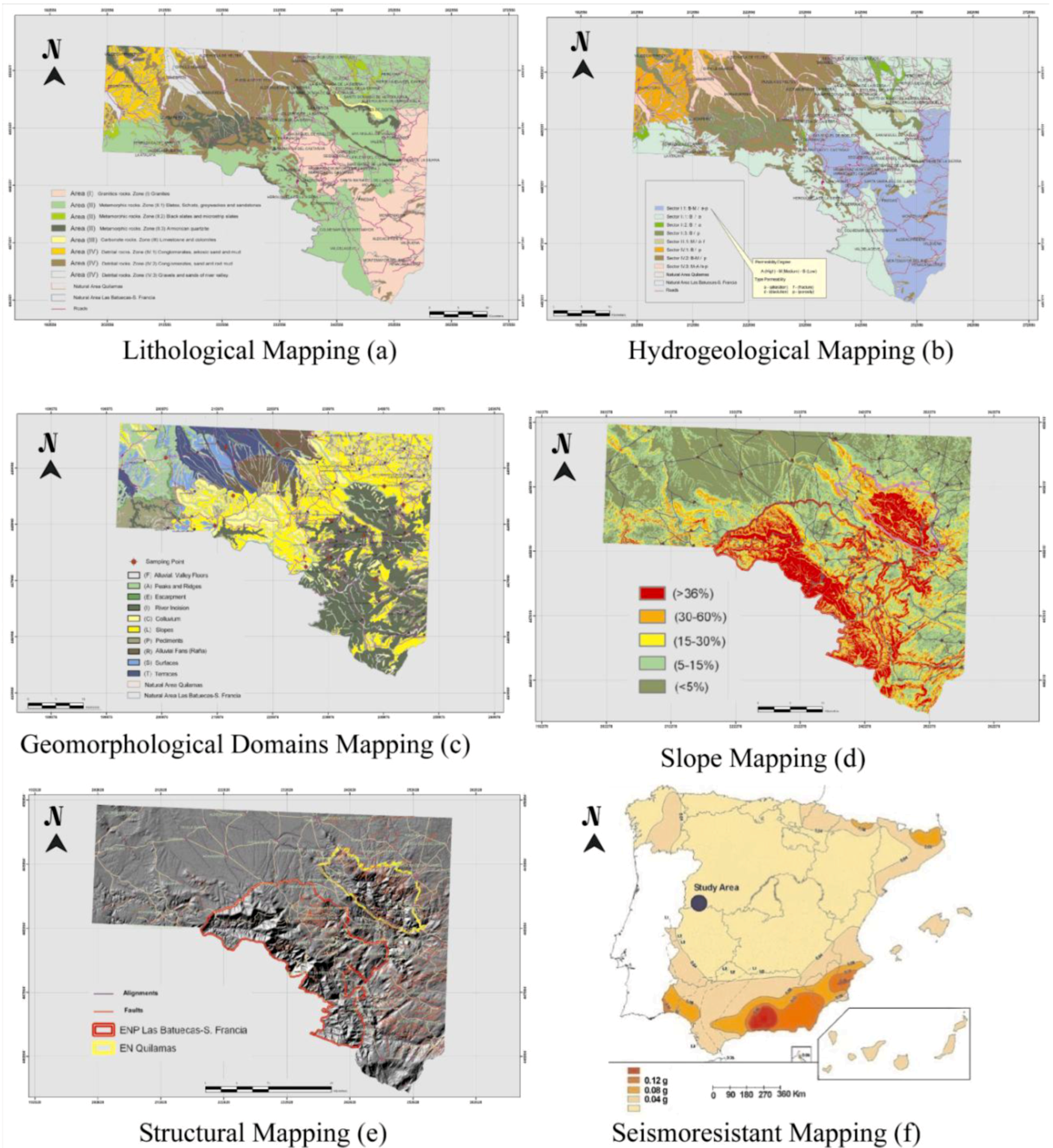
Figure 3.
Parametric cartography for the sector of study: (a) Lithological mapping; (b) hydrogeological mapping; (c) geomorphological domains mapping; (d) slope mapping; (e) structural mapping and (f) seismoresistant mapping.
Figure 3.
Parametric cartography for the sector of study: (a) Lithological mapping; (b) hydrogeological mapping; (c) geomorphological domains mapping; (d) slope mapping; (e) structural mapping and (f) seismoresistant mapping.
The hydrogeological characteristics were then analysed (hydrogeological units) using hydraulic parameters, which reclassified the previous areas (I, II, III and IV) by differentiating the more concrete lithological aspects that include the degree (high place: >1 × 10
−1 cm/s, middle: 1 × 10
−1–1 × 10
−5 cm/s and low: <1 × 10
−5 cm/s) [
21] and type of permeability (for porosity, fracturation, dissolution and alteration) for the different hydrogeological units. Permeability due to dissolution is limited to the limestone unit. Permeability due to fracturing is observed in all the lithologies, but the W sector has a lower density of fractures. Permeability due to porosity is mainly distributed in Quaternary detritic materials associated with water courses. Finally, permeability due to alteration is governed by the differential alteration of the various materials, their thickness and alteration intensity differing according to the environmental conditions of each sector. Thus, for example, the granite in the locality of La Alberca shows an alteration profile of dozens of meters, generating an arenization with low-medium permeability due to weathering and the porosity of the sandy detritic sediments. In contrast, the presence of slates has generated a lower degree of alteration, leading to clayey materials, which are less permeable. This methodology generated a synthetic mapping, with eight zones differentiated by their hydrogeological characteristics (
Figure 3b).
Further, the synthetic map of geomorphologic domains was generated and includes fundamental relief aspects to identify the most relevant geomorphologic aspects [
22,
23] that influence the geotechnical characterisation; “sectors” were created for morphologically similar and lithologically different areas (
Figure 3c). Likewise, the slopes that concern each geomorphologic domain come from the mapping of slopes generated from the digital model terrain (
Figure 3d) and the structural mapping (lineaments and fractures) (
Figure 3e) that illustrates the weak zones in the area. The lineaments reflect a structural arrangement: alignments of the topography, straight lines on the drainage network, and changes in or a noteworthy absence of rocky outcrops. Its causes may be due to lithostructural modelling or to deformation of the materials or hidden faults. These lineaments were obtained from the interpolation of topographic data of the terrain from the digital terrain model.
The R.D 997/2002 seismo-resistance norm for construction—antiseismic building code [
24]—establishes the level of seismicity by means of seismo-resistance mapping (
Figure 3f), on the basis of the basic seismic acceleration (the value of the horizontal acceleration of the surface of the terrain) and bearing in mind the amplification of seismic waves and the elastic response of the geotechnical characteristics of the terrain. As regards construction, sectors with values lower than 0.04 g, where “g” is gravity; do not have a seismic risk.
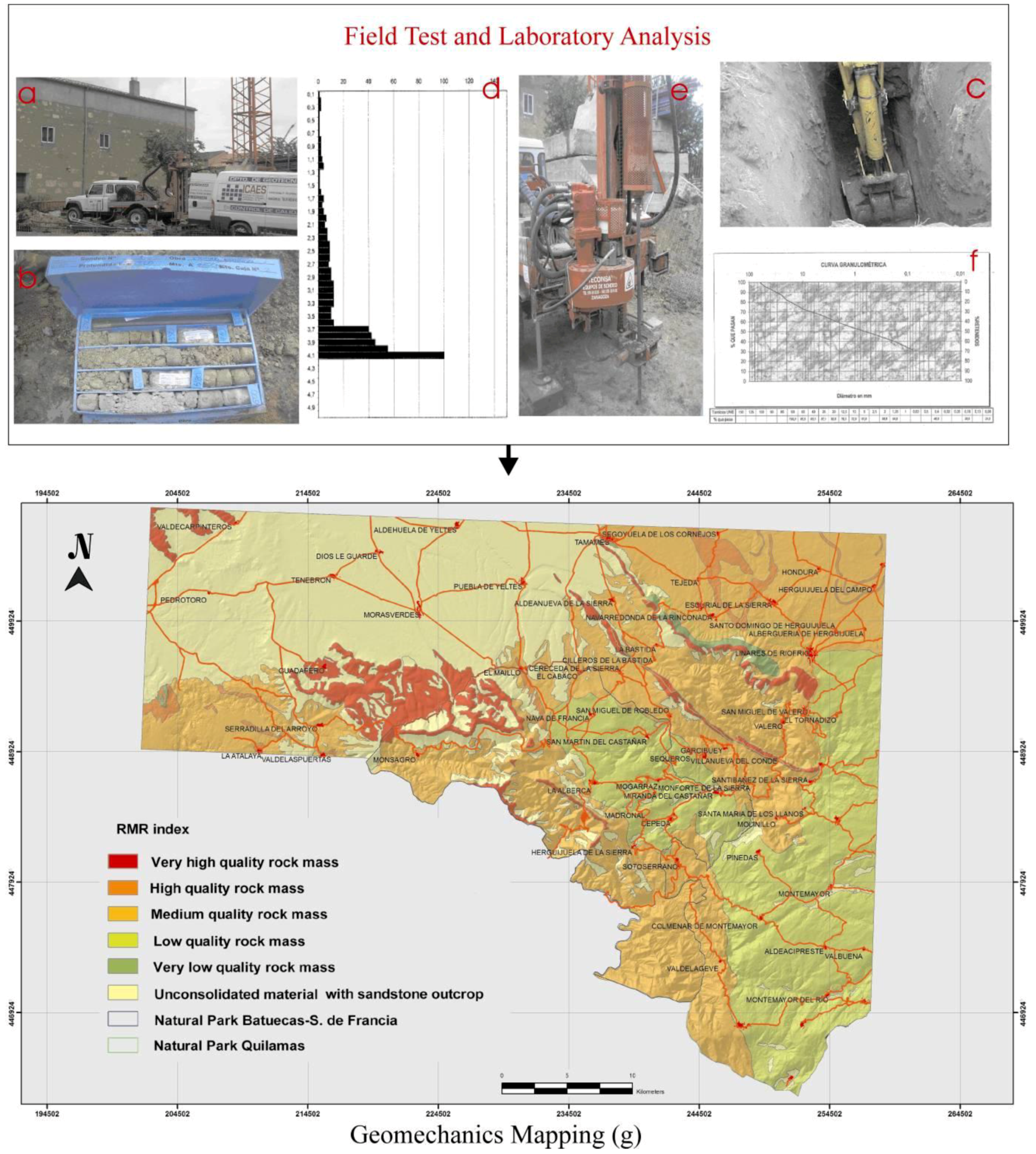
In the second phase, the geotechnical characterisation of the different lithological materials includes characterisation of different rocky massif outcrops according to the RMR geomechanical classification (Rock Mass Rating) [
25] (analysis of discontinuities: orientation, spread, continuity, ruggedness, resistance for sclerometer or Schmidt’s impact testers, openings, landfills and filtrations), characterisation of soils by withdrawing samples for laboratory analysis (granulometric analyses, textures of soils, mineralogical characterisation, Atterberg’s limits and simple compressions) and in-field tests (boreholes and dynamic penetrations). This characterisation consists of the pressures acting on the area (the degree of alteration of the rock unit), of the most common bedrock types in the study area (such as isolated or continuous footings), of the ease of excavation (altered non-rocky formations or young Quaternary sediments), and of the formations of the unaltered bedrock. Non-rippable Neocene arkoses and metasediments are excavated using machines, while other lithologies, such as granites, quartzites, slates, schists and limestones, are un-rippable and are therefore excavated using explosives. This characterisation aids in the compartmentalisation of the geomechanical characteristics in our studied zone and the generation of the geomechanical mapping (
Figure 4g).
Figure 4.
Field Test: (a) borehole; (b) borehole sample box; (c) pits; (d) dynamic penetration graph result; (e) dynamic penetration machine; (f) granulometric analysis and (g) Geomechanics mapping.
Figure 4.
Field Test: (a) borehole; (b) borehole sample box; (c) pits; (d) dynamic penetration graph result; (e) dynamic penetration machine; (f) granulometric analysis and (g) Geomechanics mapping.
In a third phase, the overlapped maps and materials were grouped by homogeneous characteristics that allowed us to establish zones in which the response of the area was similar, according to the geotechnical behaviour, which generated the geotechnical mapping (
Figure 5). This geotechnical mapping analyzes the lithological (bedrock and surficial deposits), hydrogeological (fractures-diaclases and permeability), geomorphological (domains and slopes) and geotechnical (geomechanical and seismicity) characteristics, which allowed the stability conditions of the terrain to be established (
Table 1). Analysis of the W sector of the study zone, e.g., the locality of Pedrotoro, covers area IV (formed by Neogene arkoses and Quaternary detrital materials made up of alluvial fans and terrace deposits associated with river banks, hillside deposits colluvial-, scree-, and alluvial sediments on valley floors), and zone IV1 comprises gravels, and arkosic sandstones and slates. The superposition of the hydrogeological layer indicates a low permeability (B) due to porosity, an absence of fractures in the structural mapping being observed. The superposition of the geomorphological domain mapping indicates a domain of colluvial hillsides. Finally, the geomechanical mapping shows that the zone has unconsolidated materials and sandstone outcrops, the geomechanical characteristics being obtained from field work (a borehole,
Figure 4a,b) with a depth of 10 m that provided a single continuous core; two cuts of 4 m depth performed with a back hoe (
Figure 4c), and continuous dynamic penetration, constrained to the greatest depth mechanically possible (
Figure 4d,e), together with laboratory assays (granulometric analysis
Figure 4f and Atterberg limits). The assays revealed that the degree of alteration of the arkose, reached a depth of 4 m, as confirmed by the recoil of the dynamic penetration device, pointing to a consolidated arkose as from that depth. Above a depth of 4 m, substrate is seen in the first two meters, corresponding to gravels of the colluvial hillside materials, with a sandy matrix from the weathering of sandstone. Between 2 and 4 m, the substrate is mainly made up of sands with a fine silt fraction, as seen from the granulometric curves.
Figure 5.
Geotechnical mapping.
Figure 5.
Geotechnical mapping.
In this geotechnical cartography, the 10 points for the sampled soil are indicated. The parameters obtained for these points were the depth of the unaltered bedrock; the typology of soil according to the unified system of classification of soils; and the type of dominant clay (illite, montmorillonite, kaolinite, smectite, chlorite or goethite).
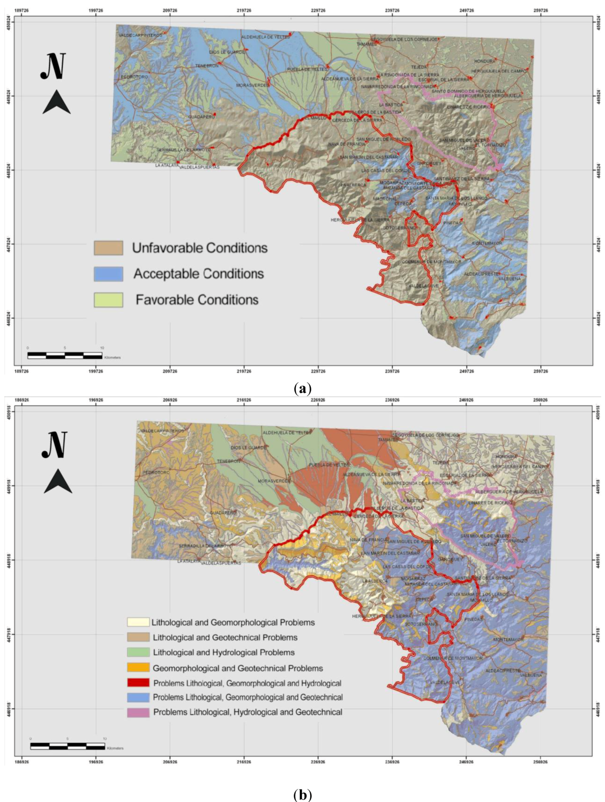
Finally, in the fourth phase, using the previous geotechnical characterisation, it was possible to establish the stability conditions of the terrain (
Table 1) and a mapping of natural hazards was generated (
Figure 6a). The mapping of natural hazards illustrates the different processes that can produce lithological, geomorphologic, hydrological and/or geotechnical problems. These are described for the different zones in Results. This cartographic analysis considered the recommendations of the international commission of geotechnical mapping [
26,
27,
28,
29], which is a basic mapping used for the anticipation risks [
30]. Additionally, the matrix of the conditions permitting construction was considered (
Table 2), in which the different zones are contrasted with the sectors (geomorphological domains: escarpments, foothill and alluvial fans (raña), hillsides, colluvial hillsides, terraces, fitted valleys, alluvial river beds and ridges: favourable (F), acceptable (A) and unfavourable (U) conditions are shown, and this allowed us to establish the mapping of geotechnical hazards (
Figure 6b). The classification criteria used to define the conditions viable for construction came from the analysis of the stability obtained for each geomorphological domain on the basis of all the parameters used in the natural hazard mapping. This mapping allowed us to determine which sectors were favourable for the emplacement and installation of different construction works (buildings, schools, and infrastructures (roads), installation of power lines systems
etc.), affording, in preliminary phases, knowledge about the behaviour of the terrain to be integrated in order to take advantage of the capacity and stability of certain sectors of the natural park.
Figure 6.
(a) Natural hazard mapping and (b) geotechnical hazard mapping.
Figure 6.
(a) Natural hazard mapping and (b) geotechnical hazard mapping.
Table 1.
Area and subarea with the lithological, hydrogeological, geotechnical and stability characteristics.
Table 1.
Area and subarea with the lithological, hydrogeological, geotechnical and stability characteristics.
| Area/Subarea | Characteristics |
|---|
| Lithological | Hydrogeological | Geotechnical | Stability |
|---|
| I | Granites | Permeability Low-Medium due to alteration or porosity | High load capacity and acceptable settlement | Stable at summitsUnstable on colluvial hillsides |
| II | 1 | Slates, schists, greywackes, sandstones and quartzites | Low permeability for alteration | Low load capacity in altered zones and different degrees of settlement | Unstable on hillsides on gentle slopes |
| 2 | Microstriped slates and black pelitic with phosphates and pyrites | Very Low-Low Permeability due to alteration | Stable on pediments on gentle slopes |
| 3 | Armorican quartzite | Very Low Permeability due to porosity | High load capacity and acceptable settlement | Stable at summits Unstable on hillsides and escarpments |
| III | Limestones, dolomites, and calcareous gaps | Medium Permeability due to dissolution or fracture | High load capacity in unaltered zones and low-dissolution zones and different degrees of settlement | Stable in unaltered zonesUnstable due to dissolution: subsidence and collapses |
| IV | 1 | Gravels, sandstones and arkosic shales | Low permeability due to porosity | Medium-High load capacity and without settlement | Stable on pediments Unstable on hillsides and escarpments |
| 2 | Conglomerates, gravels, sands and red muds | Low, medium permeability due to porosity | Low load capacity due to ground water and a medium degree of settlement | Unstable due to gravity and the effects of groundwater |
| 3 | Gravels, sands and free silt | Medium-high permeability due to porosity | Very low load capacity and a low of degree of settlement | Stable on terracesUnstable on hillsides and flood plains |
Table 2.
Matrix capability suitability: (U) unfavourable, (F) favourable and (A) acceptable.
Table 2.
Matrix capability suitability: (U) unfavourable, (F) favourable and (A) acceptable.
| Geomorphologic domains/areas | I | II | III | IV |
|---|
| II1 | II2 | II3 | IV1 | IV2 | IV3 |
|---|
| Escarpment | U | U | U | U | U | U | U | U |
| Alluvian Fan (Raña) | U | A | A | A | F | F | F | F |
| Slopes | U | U | U | U | F | F | U | U |
| Colluvium | U | U | U | U | U | U | U | U |
| Pediment | F | F | F | F | F | A | A | A |
| Terraces | A | A | A | A | A | A | A | A |
| Fitted valley | A | U | U | U | A | A | A | A |
| Alluvial | U | U | U | U | U | U | U | U |
| Ridges | U | U | U | U | U | A | A | A |
3. Results
The cartographic procedure followed generated a geotechnical mapping for the zone of study, which differentiates the following areas.
Area I. Formed by granitic materials. These plutonic rocks comprise aplite and pegmatite intrusions that can resist erosion and disintegration from weathering. From the hydrogeological perspective, this area comprises impermeable materials in which permeability limits the area to fractures and jointing, favouring their alteration. The alteration of this granitic mass produces an intense sand alteration that promotes intergranular permeability. Therefore, the permeability is considered low to moderate because of the alteration and/or fracturation. The geotechnical characteristics are suitable, with granular, altered soils with the granite at a low depth, generating zones with high load capacity and acceptable settlement. The domains of summits and motions have high load capacity and minimal settlement, with saprolitic compact of granitic alteration and nearness of the fresh rock. The domains comprising colluvial hillsides are unstable at the superficial level against side thrust forces that promote slopes.
Area II. Formed by materials metasediments composed of the complex schist-greywackes. The lithology is primarily formed by interleaving slates, graywackes and sandstones as well as by interleaving quartzite, black slates and conglomerates. From the hydrogeological perspective, they are materials with low permeability with infiltration processes that are favoured by alteration and fracturation. This impermeability is promoted by clay formation due to alteration of these lithologies and can entirely or partially “seal” the fissures therein. From the geotechnical perspective, certain zones are highly altered and comprise different settlement in superficial foundations with isolated footings. Construction conditions are acceptable, in unaltered, or slightly upset rock. Banks with middle and high slopes can induce slides that favour the foliation planes in the slates. The quartzite and schists may yield problems with detachment or falling blocks. In this area, three zones differ, II1, II2 and II3, depending on the varying lithological and hydrogeological parameters (degree and typology of permeability).
The zone II1 is formed by slates, schists, graywackes, sandstones and quartzites; it has low permeability and slow drainage that favours the alteration processes. Zone II2 is composed of microstriped slates and black pelitic with phosphates and pyrites as well as permeability conditions little lower than the previous ones and drainage favoured by the alteration processes. Zone II3 comprises the most resistant lithology in this area: the armorican quartzite with continuous crest projections. This area has low permeability and is limited to fracturation zones. The domains comprising hillsides and scarp with high slopes generate take-offs that favour stratification planes and middle settlement in zones of intense alteration. This zone is stable in the domains that comprise summits and motions with few alterations and soft slopes.
Area III. This area is formed by carbonate rocks, limestones (primarily), dolomites, and calcareous gaps. This is an area with a minor extension in the studied zone and is limited in outcrops to the zones with the highest levels of Quilamas’s Saw (limestones of Tamames). From the hydrogeological perspective, they are considered materials with moderate permeability and the most dominant processes that affect this area are dissolution and fracturation. The load capacity is high on the compact rock with slightly significant processes of karstification; however, collapses or structure subsidence may be a problem.
Area IV. This area is formed by Neogene and Quaternary detrital materials. The primary materials that compose this area are arkoses of the Miocene with former alluvial fans covered by extensive surfaces that comprise deposits superposed with alluvial fans from the Pliocene–Quaternary (locally, “rañas”) and terrace deposits from the Pleistocene associated with fluvial riverbeds, hillside deposits (colluvial and screes), and alluvial sediments in valley funds. In the domains comprising bedrock arkoses in summits and motions with stretched slopes, the load stability and capacity is high for acceptable settlement.
Zone IV1 comprises gravels, sandstones and shales that are arkosic; this zone has low permeability and drainage that promotes intergranular porosity. This high degree of consolidation generates compacted and stabilised natural conditions; the load capacities are moderate-discharge; and this area does not contain settlement. The arcosas, with hanging middle-discharges, concentrate the rain run-off, which generates instability for the gullies and gulchs.
Zone IV2 comprises deposits of conglomerates, gravels, sands and red muds that compose Neogene alluvial fan deposits that compose an additional formation: the raña of Pliocene–Quaternary with clay light slopes that can generate gravel movement in favour of the overlain levels. The permeability of these materials is low-moderate with drainage for intergranular porosity. The groundwater level may interfere especially at the sludge levels, the load capacity is low, and the generated settlements are middle.
Zone IV3 includes materials that shape the alluvial plain deposits and valley funds. The lithology is formed by gravels, sands and free silt with low and very low slopes. The permeability of these materials is moderate-high with drainage for porosity. In the flood plains and intermittent riverbeds, the groundwater level is at a low depth and there are potential flood zones with low load capacities and likely significant settlement. The terrace deposits comprise zones with acceptable load capacities and small settlement because the detritic reorganisation adapts rapidly to the applied stresses. The colluvial and screes materials destabilise wide hillsides.
From this geotechnical mapping, by overlapping and crossing with technologies (GIS), natural hazard mapping (
Figure 6a) was generated, which shows zones according to the levels of natural danger. The high hazards are limited, from the geomorphologic perspective, to the domains comprising peaks, ridges, and summits. These can generate problems from gelifraction that produce fissures, which can induce detachment and cracking for different rock movements. The colluvial materials and falls, associated with slopes, constitute zones of high risk, given the instability of these materials and the high slopes. Given the riverbeds and river margins in these zones, the potential flood areas are Morasverdes, Tenebrilla and Yeltes, which generate hydrological problems. These zones have characteristic lithologicies, groundwater levels at low depths, and low load capacities. They can generate ponds in partially depressed zones, including level surfaces because the clay accumulation induces deficient drainage. The fluvial scarps can produce erosional problems associated with the occasional displacement of the principal riverbed, which generates instability and lateral erosion of the fluvial riverbed. The limestones can produce lithological and geotechnical problems, mainly karstification and hollowing from dissolution. Clay soils are located above the metasedimentary materials, in slate alterations, and in flood plains along the fluvial margins, where they demonstrate a certain plasticity that can generate geotechnical problems. This plasticity is especially unfavourable in geomorphic domains that promote mobility (fluvial incisions and hillsides in slates) and depends on the disposition of the cleavage and the degree of alteration.
Moderately hazardous sectors present an important level of competence and high load capacity. However, localized geomorphologic problems could generate detachments and cause clay slides from highly sloping altered areas as well as creeping in moderately sloping areas. The depressions in this area and in certain sectors favour localized hydrological risks.
The low-hazard areas include detritic formations without significant clay levels and constitute stable zones; the settlements are immediate and acceptable. Materials therein include alluvial fans with stretched slopes, where the hydrological and geomorphologic problems are compatible with the most frequent uses of these territories. The stability is high, and the load capacity high in the granitic zones with little fracturing and weathering, as well as in geomorphologic domains comprising motions over metamorphic rocks (e.g., quartzites and schists) with low levels of alteration.
4. Conclusions
The constant increase in different human activities as well as the commitment to protection and conservation of certain natural parks requires more sustainable development practices and integral planning for areas such that environmental risks are predictable and mitigated. To achieve this goal, the conditions and uses of the areas under scrutiny must be evaluated. This evaluation relies on the exhaustive knowledge of geodynamic external processes, which can generate different geological risks.
The geotechnical mapping in the “Las Batuecas-Sierra de Francia” and “Quilamas” Natural Parks comprises hazards that directly influence determination of geology (different resistance lithology as well as degrees and types of material permeabilities); geomorphology (areas capable of slide and creeping; lateral erosion in fluvial riverbed, detachments in screes with high slopes); hydrology in zones with hanging falls for avenues and floods; geotechnical risks from load capacity; settlement; and degree of plasticity. The generation of this natural hazard mapping demonstrates the importance of a detailed, hydrological analysis of the geomorphologic problems, lithology and geotechnology in the mapping of risks for the potential uses of the region in natural parks planning and management.
The cartographic procedure described here is a sufficiently effective, economical, and precise tool for initial decision making regarding the management of natural parks and their planning, and it is applicable to any natural space. These geotechnical mappings facilitate the demarcation of areas to which limitations and recommendations concerning construction activities should be applied. This method can be used for the prevention and mitigation of natural risks, and it is validated on the basis of the presence of active processes that create unfavourable conditions for construction, as illustrated by the mapping of natural hazards (
Figure 6a) that corresponds to trigger factors for these risks and is reflected in the three categories of geotechnical risks (
Figure 6b). Thus, in recent years different active processes have been recorded (landslides and rock falls,
etc.) in the study zone. These movements have caused fatal injuries and damage to infrastructures (roads and bridges) and buildings. The field work, its publication in different journals, and the analysis of requests for help from the Regional Government by town councils have allowed us to make an inventory of these sectors and include them on the maps obtained here, validating the procedure since they coincide with zones that are unfavourable for construction.
The results of the present work allow us to confirm that the mapping of natural hazards from thematic maps at a scale of 1:50,000, characterised by a series of assays representative of each geotechnical area and zone, offers a useful tool for the governance of future human activity in natural parks. The results of the field work and laboratory assays of geotechnical reports, both public and private, offer a geotechnical database of geomechanical parameters that can be used in this procedure, thereby decreasing the number of assays that need to be performed and the economic costs involved.
In Spain, in recent years maps addressing hazards have been drawn up for certain areas of reduced extension, usually within large cities and their surroundings, but not at regional level, in which geotechnical maps at a scale of 1:200,000 are used. The present work improves the methodology for regional territorial sectors, and the results reported here are based on a combination of classic mapping techniques and GIS technologies. Detailed mapping of the geomorphogical domains, compiled from a precise photo-interpretation at scales of 1:10,000 and 1:18,000 is of great importance for the correct differentiation and demarcation of the different sectors for their evaluation in combination with other already available maps since it can be used to determine land sectors that are susceptible to instability.
The potential beneficiaries of these maps are the managers of natural parks and directors of protected natural spaces, since the maps will allow such agents to make decisions about the suitability of authorizing, or not, the emplacement of different types of construction (buildings and infrastructures). The municipalities affected, that are interested in doing so, will also be able to access maps for the prevention of possible risks, allowing a more rational planning of land use.


