Article

MR Damper Controlled Vibration Absorber for Enhanced Mitigation of Harmonic Vibrations

1
Maurer Switzerland GmbH, Neptunstrasse 25, 8032 Zurich, Switzerland
2
Maurer Söhne Engineering GmbH & Co. KG, Frankfurter Ring 193, 80807 Munich, Germany
3
MAURER SE, Frankfurter Ring 193, 80807 Munich, Germany
*
Author to whom correspondence should be addressed.
Actuators 2016, 5(4), 27; https://doi.org/10.3390/act5040027
Submission received: 11 November 2016 / Revised: 29 November 2016 / Accepted: 14 December 2016 / Published: 21 December 2016
(This article belongs to the Special Issue Magnetorheological Fluids, Devices, and Integrated Adaptive Systems)

Abstract

:
This paper describes a semi-active vibration absorber (SVA) concept based on a real-time controlled magnetorheological damper (MR-SVA) for the enhanced mitigation of structural vibrations due to harmonic disturbing forces. The force of the MR damper is controlled in real-time to generate the frequency and damping controls according to the behaviour of the undamped vibration absorber for the actual frequency of vibration. As stiffness and damping emulations in semi-active actuators are coupled quantities the control is formulated to prioritize the frequency control by the controlled stiffness. The control algorithm is augmented by a stiffness correction method ensuring precise frequency control when the desired control force is constrained by the semi-active restriction and residual force of the MR damper. The force tracking task is solved by a model-based feed forward with feedback correction. The MR-SVA is numerically and experimentally validated for the primary structure with nominal eigenfrequency and when de-tuning of −10%, −5%, +5% and +10% is present. Both validations demonstrate that the MR-SVA improves the vibration reduction in the primary structure by up to 55% compared to the passive tuned mass damper (TMD). Furthermore, it is shown that the MR-SVA with only 80% of tuned mass leads to approximately the same enhanced performance while the associated increased relative motion amplitude of the tuned mass is more than compensated be the reduced dimensions of the mass. Therefore, the MR-SVA is an appropriate solution for the mitigation of tall buildings where the pendulum mass can be up to several thousands of metric tonnes and space for the pendulum damper is limited.

1. Introduction

Wind-induced excitation forces may lead to structural vibrations with extremely large amplitudes as observed on the Volgograd Bridge, Russia, in 2010 or on the Taipei 101, Taiwan, during typhoons in 2008, 2013 and 2015 [1,2,3,4]. The oscillation amplitudes are maximized if all excitation energy is transferred into one vibration mode of the structure, which is the case when the excitation mechanism such as vortex shedding generates harmonic excitation forces [5]. The common measure to reduce large amplitude vibrations is the installation of a tuned mass damper (TMD) at the anti-node of the mode that is most susceptible to wind-induced excitation forces [6]. The design of the natural frequency and damping ratio of the TMD for minimum structural displacement amplitudes are given by the well-known formulae of Den Hartog [6]; in case of residential and office buildings TMDs are usually designed for minimum acceleration response of the structure [7]. Due to the damping ratio of the TMD that is produced by a linear dash pot damper the TMD reduces but cannot cancel vibrations because the viscous force slightly reduces the amplitude of the spring force of the TMD whereby the spring force does not fully compensate for the excitation force [6,8]. However, the benefit of dash pot damper of the TMD is that the damping element makes the passive TMD most insensitive to changes in the excitation frequency. This feature is also known as H infinity optimality of the passive TMD for broadband excitations. This means that the TMD is the best passive device when the primary structure is excited by excitation forces with white noise characteristics whereby the structure responds at all frequencies. However, in practice, the displacement amplitudes of the springs and dash pot damper of the TMD must be designed for the case of maximum TMD relative motion amplitude which occurs when the primary structure is excited by single harmonic disturbing forces due to, e.g., vortex shedding. Readers are referred to several videos available on the Internet of the swaying pendulum TMD of the Taipei 101 demonstrating that large TMD relative motion amplitudes result from single harmonic oscillations of the primary structure [4]. This means that the TMD represents to common passive mass damper for the reduction of both broadband and single harmonic structural vibrations. In order to compensate for time-varying modal properties of the primary structure due to, e.g., environmental impacts or to improve the mitigation efficiency in the vicinity of the targeted structural eigenfrequency adaptive TMDs have been developed. These devices rely on actively controlled spring systems, Piezo stacks, shape memory alloys, controllable dampers such as magnetorheological (MR) dampers and other types of actuators [2,3,9,10,11,12,13,14,15,16,17,18,19,20,21]. According to the literature the resulting vibration mitigation is improved by up to 50% compared to the passive TMD [17,18].
Another type of mass damper is the undamped dynamic vibration absorber that was invented by Frahm and patented in 1909 [22]. This device is a spring mass oscillator without dash pot damper whose natural frequency is equal to the known and constant disturbing frequency, e.g., the frequency of the resonance rotational speed of a machine [23]. Due to this frequency tuning and the absence of a damper the spring force is equal and opposite to the disturbing force at all instants whereby the primary structure does not vibrate at all [6]. Hence, the undamped dynamic vibration absorber cancels completely single harmonic vibrations of the structure if the excitation frequency is known and time-invariant which is the reason that the vibration absorber is also called vibration neutralizer. Consequently, the concept of the undamped dynamic vibration absorber is highly preferable for controlled mass dampers if the task is to maximally reduce harmonic vibrations with time-varying frequencies. Such controlled vibration absorbers may be based on electrical actuators, shape memory alloys, electrorheological dampers, MR elastomers and MR dampers that allow adjusting in real-time the controllable frequency of the absorber to the actual frequency of vibration [8,24,25,26,27,28,29,30,31,32].
This paper describes a semi-active vibration absorber (SVA) based on a real-time controlled MR damper (MR-SVA) that generates the real-time frequency adaptation according to the principle of the vibration absorber by the emulation of a controlled stiffness force. In parallel to the controlled stiffness force the MR damper is controlled to also emulate a controlled damping force to keep the relative motion of the absorber mass within practical limits. As damping in the SVA significantly lowers the vibration reduction in the primary structure the damping emulated by the MR damper is minimized by a nonlinear adaptive damping control approach. The paper is structured as follows. The basic principle of the MR-SVA is presented in Section 2 and the control algorithm is described in Section 3. Section 4 shows the numerical and Section 5 the experimental validations of the MR-SVA. Section 6 describes the behaviour of the MR-SVA of the Danube City Tower in Vienna, Austria, and shows that the concept of the MR-SVA allows reducing the absorber mass by 20% without losing performance at worst-case excitation of the primary structure. Finally, a summary with concluding remarks is given. It is understood that parts of this entire R & D work that started in 2010 with the project of the Volgograd Bridge [2,3,18] and is still continuing can be found in the existing literature. The aim of this paper is therefore to give a comprehensive description of this R & D work to show the continuous further developments and—as a final outcome of this longtime work—describe the latest improvement that the MR-SVA can be operated with reduced damper mass almost without any losses in vibration reduction efficiency.

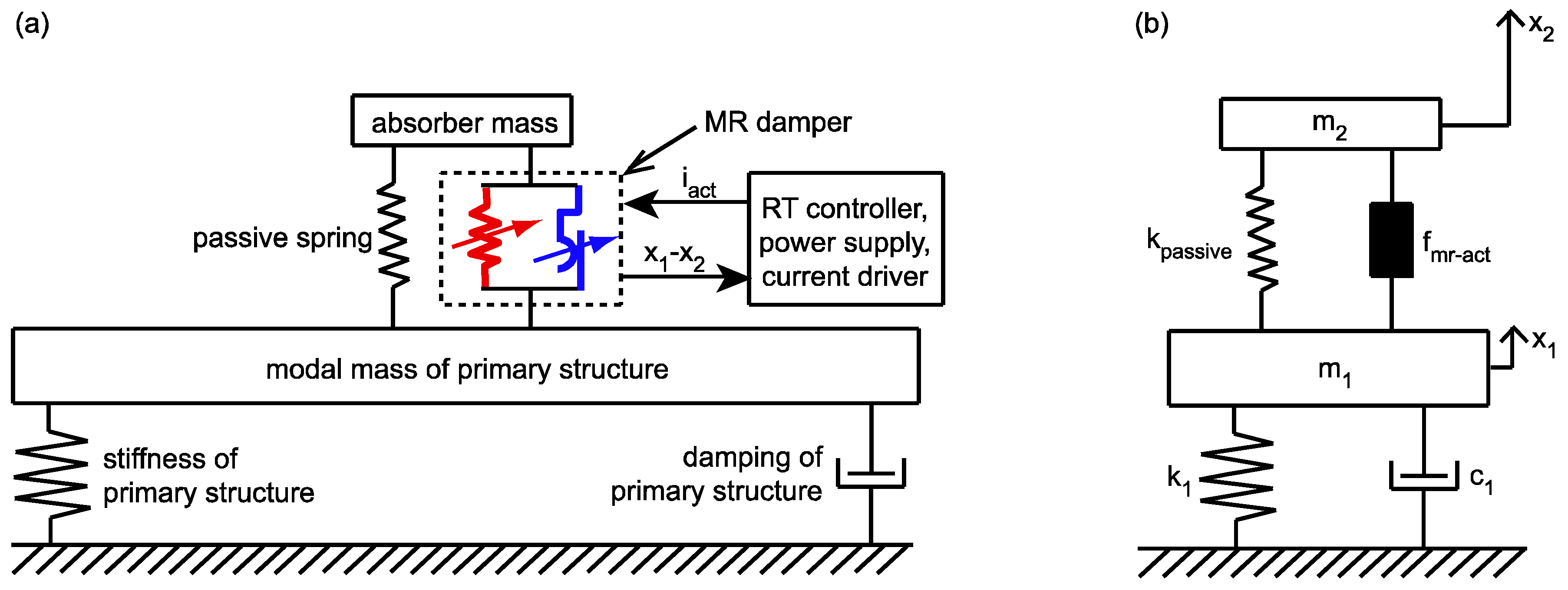
2. Concept of MR-SVA

2.1. Control Objectives

The MR-SVA is composed of a passive mass spring packet and an MR damper in parallel (Figure 1a). The desired MR damper control force is formulated to produce the behaviour of the undamped dynamic vibration absorber according to Frahm for the actual frequency of vibration in order make advantage of the fact that the undamped dynamic vibration absorber can eliminate vibrations [6,22]. Thus, the main control objectives of the MR-SVA are:
  • its controlled frequency is equal to the actual frequency of vibration at all instants, and
  • its controlled damping is minimized under the constraint that the relative motion amplitude of the absorber mass must not be greater than its maximum tolerable value.

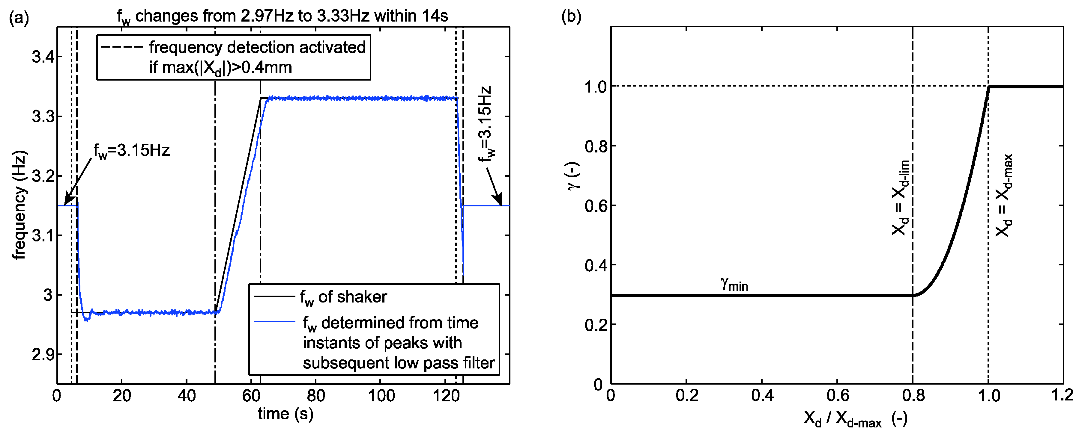
2.2. Real-Time Frequency and Damping Controls with MR Damper

In order to realize the above mentioned control objectives the actual MR damper force is controlled in real-time to emulate:
  • a controllable stiffness force to tune the controllable frequency of the MR-SVA to the actual frequency of vibration, and
  • a controllable damping force to minimize the damping and control the relative motion amplitude of the absorber mass.
The natural frequency f p a s s i v e of the passive mass spring packet is designed to be equal to the targeted eigenfrequency f 1 of the primary structure. This leads to the following stiffness coefficients that are emulated by modulation of the dissipative MR damper force during each cycle:
  • zero stiffness when the disturbing frequency f w is equal to the targeted eigenfrequency f 1 of the primary structure, i.e., f w = f 1 , whereby the controlled frequency f c o n t r o l of the MR-SVA is equal to f w , i.e., f c o n t r o l = f w .
  • positive stiffness if f w > f 1 in order to augment the total stiffness of the MR-SVA that is the sum of the passive spring stiffness and the controlled stiffness emulated by the MR damper to generate f c o n t r o l = f w .
  • negative stiffness if f w < f 1 in order to diminish the total stiffness of the MR-SVA to produce f c o n t r o l = f w .
The desired energy dissipation is produced by energy equivalent friction damping as the combined emulations of friction and stiffness forces in MR dampers minimize the amount of active forces that need to be clipped to zero and lead to precise stiffness and therefore precise frequency control of the MR-SVA [33,34,35].

2.3. Control Based on Measured Collocated Displacement

The control algorithm is programmed based on the measured relative motion x 1 x 2 of the MR-SVA that is identical with the MR damper displacement (Figure 1b). The actual frequency f w of vibration, which is required for the computation of the controllable stiffness force, is derived in real-time from the time instants of the peaks of x 1 x 2 after each half period [21]. The actual relative motion amplitude X d of the MR-SVA, which is needed for the computation of the controlled friction force, is estimated by the latest amplitude of x 1 x 2 [21].

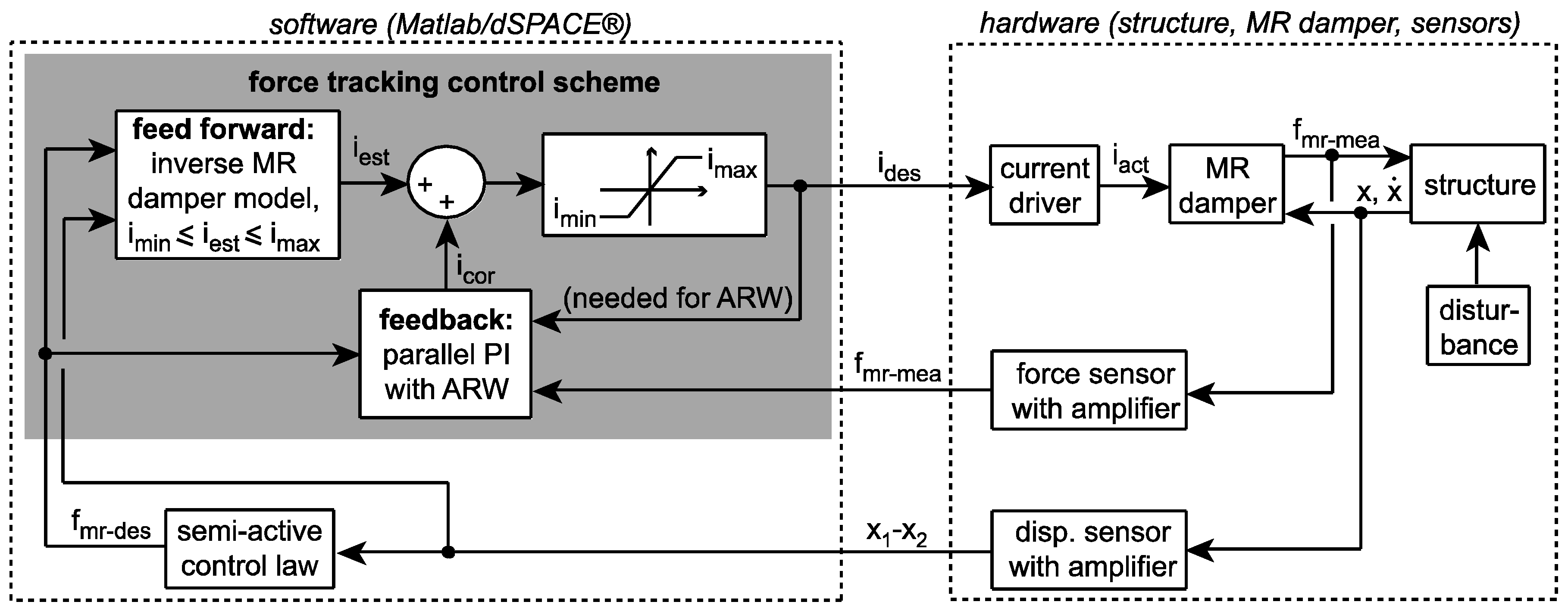
2.4. MR Damper Force Tracking Control Scheme

The desired MR damper current i d e s is computed by a model-based feed forward, which is based on an inverted Bingham model of the MR damper, and corrected by a linear feedback based on the difference between desired control force and actual MR damper force that is measured by a load cell [36]. The desired current is input to the current driver that generates the actual MR damper current i a c t i d e s .

3. Control Algorithm

3.1. Stiffness of Passive Spring

The stiffness k p a s s i v e of the passive spring of the MR-SVA is designed according to the principle of the vibration absorber, i.e., the natural frequency f p a s s i v e of the passive mass spring system is equal to eigenfrequency f 1 of the targeted mode of the structure (Figure 1b)
k p a s s i v e = m 2 ( 2   π   f p a s s i v e ) 2 = m 2 ( 2   π   f 1 ) 2 ,
where m 2 denotes the absorber mass.

3.2. Controlled Frequency

The target is that the controlled frequency f c o n t r o l of the MR-SVA is equal to the disturbing frequency f w of vibration at all instants t :
f c o n t r o l ( t ) = f w ( t ) .
The disturbing frequency is assumed to be harmonic and is determined from the time instants of the extrema of the measured absorber relative motion and MR damper displacement, respectively, since the absorber and the structure as well vibrate at the frequency of the disturbing force. A low pass filter that attenuates fluctuations in the detected disturbing frequency increases the time delay to approx. 5 s which seems to be acceptable considering that typical transients of the disturbing frequency due to time-varying life loads on the structure are slower [21] (Figure 2a). To generate the targeted frequency tuning given in Equation (2) the desired stiffness k d e s to be emulated by the MR damper is the difference between the total desired stiffness of the MR-SVA and the passive spring stiffness.
k d e s = m 2 ( 2   π   f w ) 2 k d e s t o t a l m 2 ( 2   π   f p a s s i v e ) 2 k p a s s i v e
The desired stiffness force that is to be tracked in real-time by the MR damper therefore becomes
f k d e s = k d e s   ( x 1 x 2 ) ,
where x 1 x 2 denotes the relative motion of the absorber mass and MR damper, respectively, which is measured by a displacement sensor. Due to the design (Equation (1)) of the passive spring stiffness f k d e s becomes zero if f w = f 1 which minimizes the maximum control forces in the MR damper due to the frequency control of the MR-SVA.

3.3. Controlled Adaptive Damping

The relative motion amplitude X d of mass dampers is limited due to spatial limitations within the structure, e.g., the free height within the bridge girder, and due to deformation limits of the springs. Therefore, the MR damper is used to produce a controlled damping force to avoid that the absorber mass hits the structure or the coil springs are compressed to their bloc length. However, as damping produced in the absorber reduces its vibration reduction efficiency the desired damping is minimized when X d is far below its maximum tolerated value X d m a x while the damping is set to its nominal value if X d = X d m a x . It is suggested that the nominal damping corresponds to that given by Den Hartog’s design whereby the nominal desired viscous damping coefficient for X d = X d m a x and formulated for the actual frequency f w becomes
c d e s n o m i n a l = 2   ζ a d a p t i v e   m 2   ( 2   π   f w ) ,
where ζ a d a p t i v e denotes the damping ratio according to Den Hartog [6] but formulated for f w :
ζ a d a p t i v e = 3   μ a d a p t i v e 8   ( μ a d a p t i v e + 1 ) 3 .
In Equation (6), μ a d a p t i v e denotes the time-varying mass ratio m 2 / m 1 a c t u a l where m 1 a c t u a l describes the actual modal mass of the primary structure that may vary over time due to changing life loads. μ a d a p t i v e can be computed in real-time from the detected actual frequency of vibration as follows:
μ a d a p t i v e = m 2 m 1   ( f w f 1 ) 2 .
Assuming time-invariant stiffness of the primary structure. Due to the design given by Equation (5) the nominal desired viscous damping coefficient is equal that of the passive TMD if f w = f 1 whereby the performances of the MR-SVA and passive TMD become comparable. In order to minimize the damping of the MR-SVA whenever possible the adaptive damping gain γ is introduced to reduce the desired viscous damping coefficient if the actual relative motion amplitude X d is not in the vicinity of X d m a x :
c d e s = γ   c d e s n o m i n a l ,
where γ is formulated as function of the actual relative motion amplitude X d as follows:
γ = { γ m i n : X d X d l i m γ m i n + ( 1 γ m i n ) ( X d X d l i m ) 2 ( X d m a x X d l i m ) 2 : X d l i m < X d < X d m a x 1 : X d X d m a x ,
where X d l i m denotes the relative motion amplitude up to which γ is set to its minimum value γ m i n and X d , X d l i m and X d m a x are positive quantities. The proposed design of γ described by Equation (9) is plotted in Figure 2b for γ m i n = 0.30 that is used for the control of the mock-up (prototype) MR-SVA as the desired damping due to γ m i n = 0.30 approximately corresponds to the damping that is generated by the residual force of the MR damper which cannot be avoided. For X d X d l i m , γ = γ m i n reduces the desired damping to 30% of its nominal value, for X d X d m a x the desired damping is equal to its nominal value (Equation (5)) and for X d l i m < X d < X d m a x a quadratic function is designed to generate a smooth transition between the minimum desired damping and the nominal desired damping. For further safety against over travelling of the absorber mass during transient vibrations shock impact dampers are installed at 110% of X d m a x . The desired viscous damping coefficient c d e s is emulated in the MR damper by energy equivalent friction damping. The according desired friction force is
f f d e s = s g n ( x ˙ 1 x ˙ 2 )   F d e s = s g n ( x ˙ 1 x ˙ 2 )   { π 4   c d e s   ( 2   π   f w )   X d } ,
where x ˙ 1 x ˙ 2 denotes the relative velocity of the absorber mass and MR damper, respectively, s g n is the signum function and F d e s is the desired friction force amplitude. As Equation (10) shows F d e s requires to be adjusted in proportion to the actual displacement amplitude X d of the MR damper in order to ensure energy equivalence to desired viscous damping coefficient c d e s [33,34].

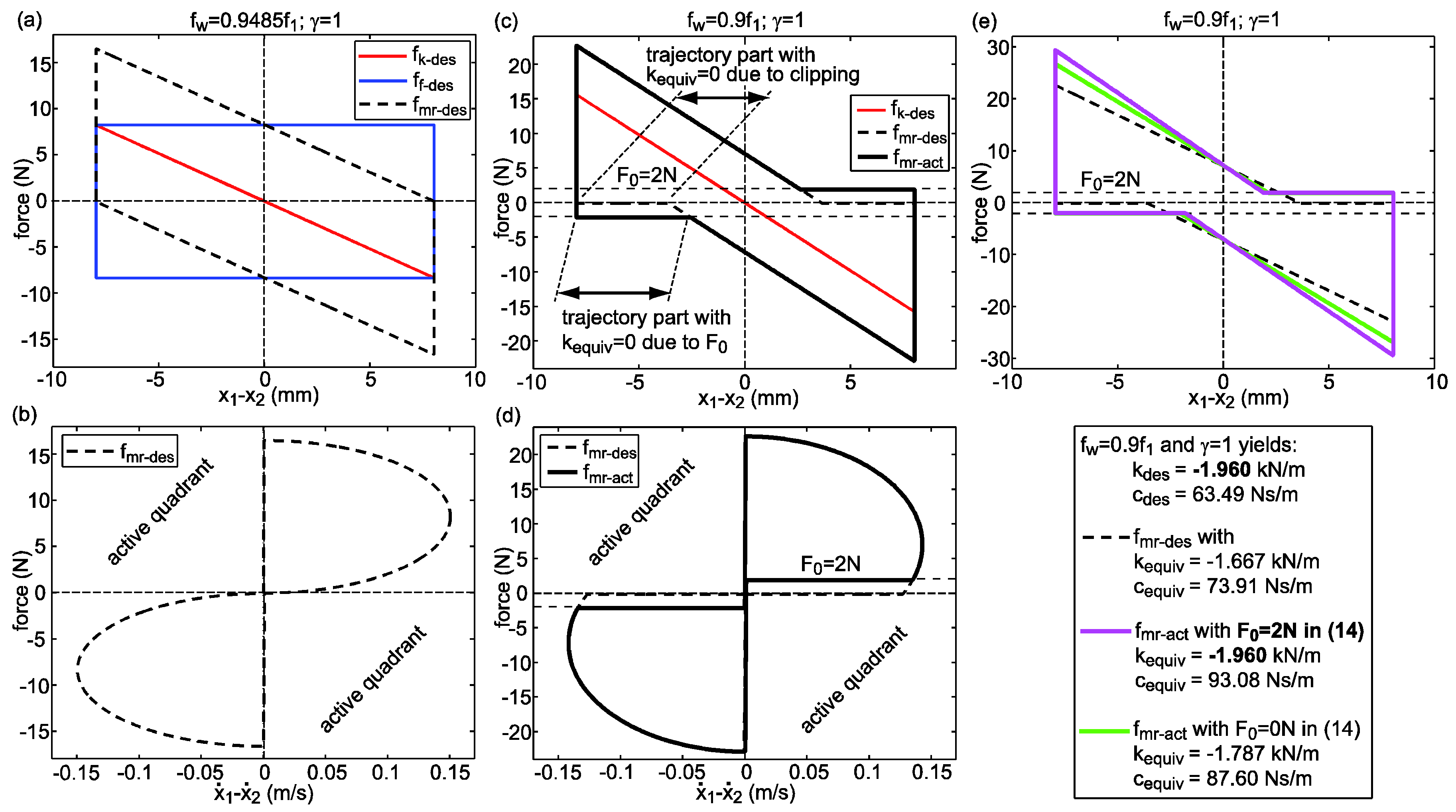
3.4. Desired Semi-Active Control Force

The sum of the desired stiffness force (Equation (4)) and the desired friction force (Equation (10)) yields the desired control force of which the active desired control forces are clipped to zero since MR dampers cannot generate active forces. This yields the desired semi-active control force to be tracked by the MR damper as follows:
f m r d e s = { f k d e s + f f d e s :   ( x ˙ 1 x ˙ 2 )   ( f k d e s + f f d e s ) 0 0 :   ( x ˙ 1 x ˙ 2 )   ( f k d e s + f f d e s ) < 0 .
Due to the formulation of the desired viscous damping by energy equivalent controlled friction damping the sum f k d e s + f f d e s does not yield active desired control forces if | k d e s | F d e s / X d that is shown in Figure 3a,b by the limit case | k d e s | = F d e s / X d whereby clipping is not activated. In contrast, the superposition of a desired stiffness force and a desired viscous force includes active desired forces independent of | k d e s | [34]. Hence, the approach to combine the desired stiffness force with the energy equivalent friction force is highly appropriate for MR dampers as this method minimizes the amount of active forces that are clipped to zero.

3.5. Actual Semi-Active Control Force

The desired semi-active control force f m r d e s is constrained by the residual force F 0 of the MR damper that is simplified here by the Coulomb friction model whereby the actual semi-active MR damper force becomes
f m r a c t = { f m r d e s : | f m r d e s | F 0 s g n ( x ˙ 1 x ˙ 2 )   F 0 : | f m r d e s | < F 0 .
Although the residual force is not a pure friction force the Coulomb friction model is adopted because it allows deducing real-time applicable closed-form control solutions for precise stiffness emulation in the MR damper and therefore precise frequency control of the MR-SVA also when clipping and F 0 constrain f m r d e s which is explained in the subsequent section.

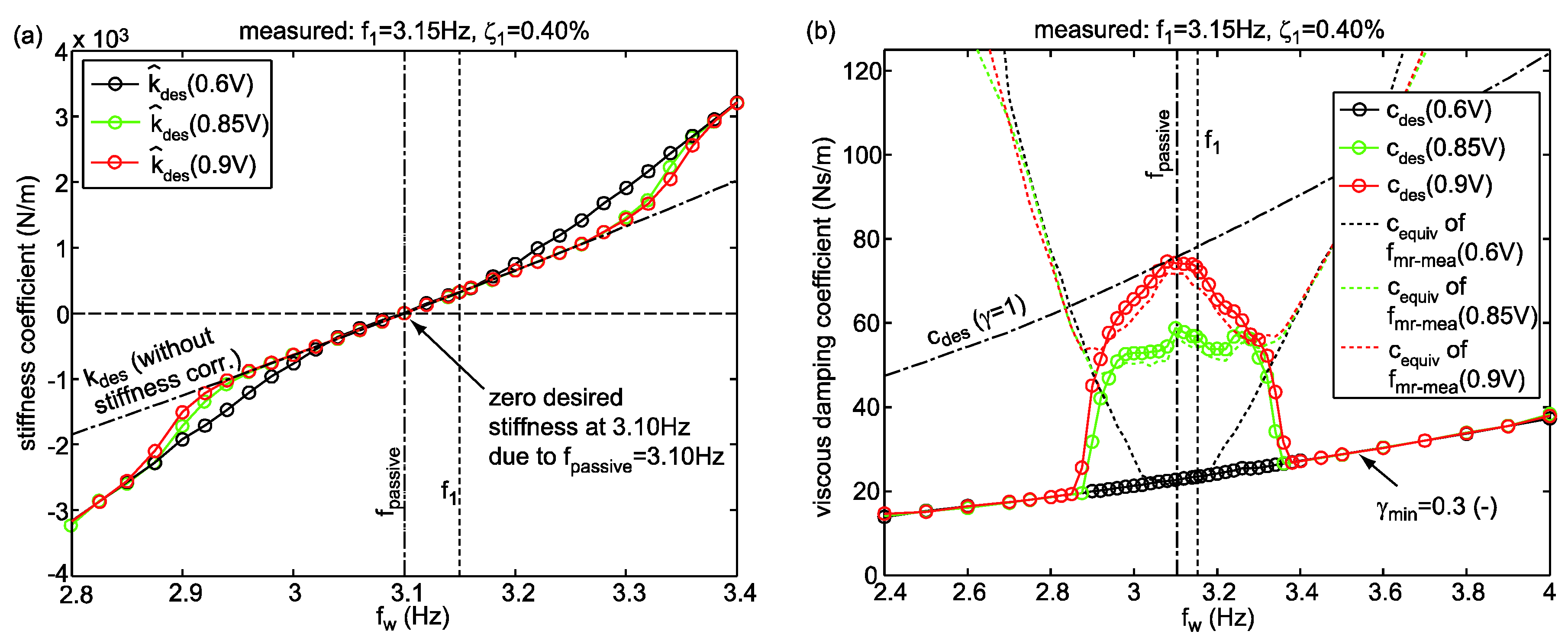
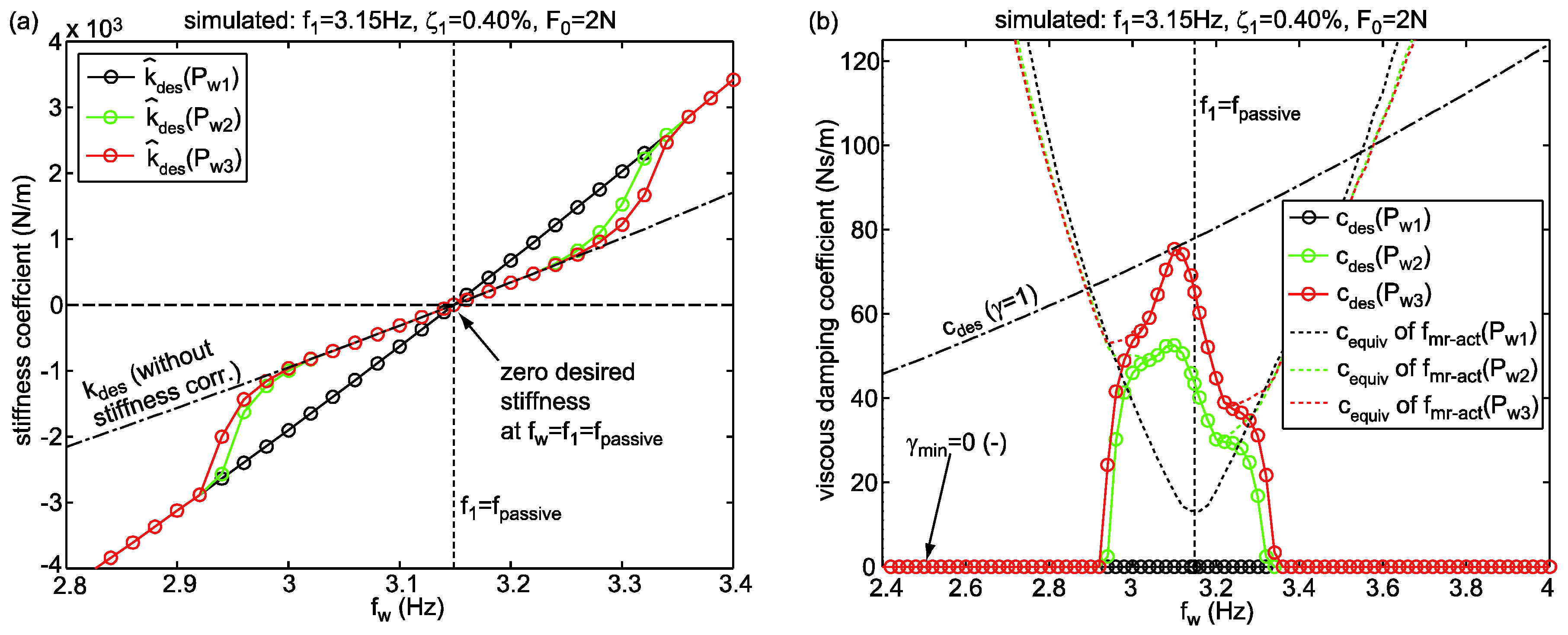
3.6. Stiffness Correction Method For Precise Frequency Control

As Figure 3c,d show the equivalent stiffness k e q u i v of actual MR damper force f m r a c t that is derived from the potential energy of f m r a c t during half a cycle [37]
k e q u i v = 1 X d 2 { 0 X d f m r a c t   d ( x 1 x 2 ) + X d 0 f m r a c t   d ( x 1 x 2 ) }
is smaller than its desired counterpart k d e s due to the clipping of active desired control forces at larger differences between f w and f 1 and due to the residual force constraint. Both the clipping and F 0 evoke force displacement trajectory parts with zero equivalent stiffness which evokes | k e q u i v |   <   | k d e s | and thereby imprecise frequency tuning of the MR-SVA. Notice that F 0 and not clipping is the decisive control force constraint for MR dampers. In order to realize the targeted precise frequency control f c o n t r o l ( t ) = f w ( t ) of the MR-SVA the desired stiffness k d e s in Equation (4) must be replaced by the corrected desired stiffness k ^ d e s ,
k ^ d e s = { k d e s : | k d e s | ( F d e s F 0 ) / X d s g n ( k d e s )   1 X d { ( F d e s F 0 X d | k d e s | ) + ( F d e s F 0 X d | k d e s | ) 2 + s g n ( F d e s F 0 )   ( F d e s F 0 ) 2 } : | k d e s | > ( F d e s F 0 ) / X d ,
such that k e q u i v of f m r a c t is equal to the originally desired stiffness k d e s . The derivation of the stiffness correction method shown in Equation (14) is described in detail in [35] but not repeated here as this would be beyond the topic of the present paper. Figure 3e demonstrates that the stiffness correction method (Equation (14)) leads to the targeted equivalent stiffness k e q u i v of f m r a c t and consequently to the targeted precise frequency control of the MR-SVA when clipping is activated and F 0 further constrains the actual MR damper force.

3.7. Compromise Solution for Stiffness Correction Method

The drawback of the stiffness correction method (Equation (14)) is that it leads to increased equivalent damping c e q u i v that is derived from the cycle energy of f m r a c t [37]
c e q u i v = 1 π   ( 2   π   f w )   X d 2 0 1 / f w f m r a c t   ( x ˙ 1 x ˙ 2 )   d t ,
which is significantly greater than c d e s and consequently lowers the vibration reduction performance of the MR-SVA as increased damping reduces the stiffness force that compensates for the disturbing force. Numerical investigations of the MR-SVA with stiffness correction method (Equation (14)) point out that maximum vibration reduction in the primary structure is obtained when the correction method described by Equation (14) is applied in the control code with F 0 = 0 N despite F 0 0 N of the MR damper in order to reduce the difference between c e q u i v and c d e s and—at the same time—to ensure that k e q u i v that is not far away from k d e s whereby the frequency tuning of the MR-SVA is not too imprecise as without stiffness correction method.

4. Numerical Validation

4.1. Assessment Criterion

The vibration reduction performance of the MR-SVA is assessed for harmonic excitation of the primary structure according to [6] by its normalized displacement response,
X 1 X 1 s t a t i c = r m s ( x 1 )   k 1 r m s ( x ¨ s )   m s ,
where X 1 is the anti-node displacement amplitude, X 1 s t a t i c = P w / k 1 is the static deflection due to the disturbing force amplitude P w at zero Hertz and the stiffness k 1 = m 1 ( 2   π   f 1 ) 2 of the primary structure. In case of the numerical validation of the MR-SVA with primary structure the steady state value of X 1 is precisely known which allows determining the criterion given by Equation (16) using the steady state amplitude X 1 . However, in case of the experimental validation X 1 slightly varies even during steady state conditions. In this case, the criterion given by Equation (16) is determined using the root mean square values (rms) of the measured anti-node displacement x 1 and the measured acceleration x ¨ s of the shaker mass m s where the rms-values are derived from ten steady state cycles of the measured quantity.

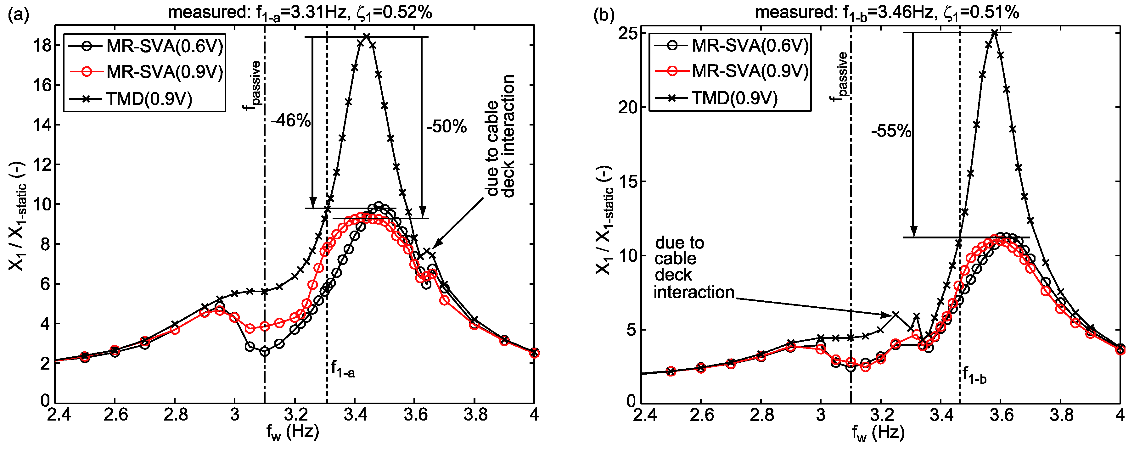
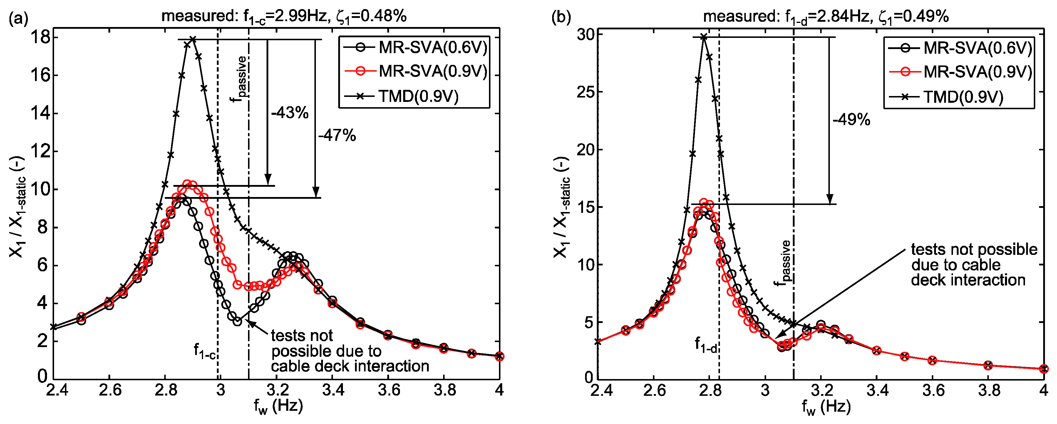
4.2. Assessment of MR-SVA for Tuned and De-Tuned Cases

The MR-SVA is developed to reduce efficiently structural vibrations not only when the modal parameters of the primary structure correspond to the values used in the design of the passive mass spring packet of the MR-SVA but also when the eigenfrequency of the primary structure changes due to time-varying life loads and environmental impacts. The MR-SVA is therefore assessed for the primary structure with nominal modal parameters and when the eigenfrequency f 1 is changed by +5%, +10%, −5% and −10% compared to its nominal value (Table 1). TMDs are usually designed already during the design phase of tall buildings where the uncertainty in f 1 is often around ±10% of its nominal value. Hence, the validations performed at the above mentioned levels of de-tuning represent realistic assessment scenarios. The following explanations for the data given in Table 1 must be added:
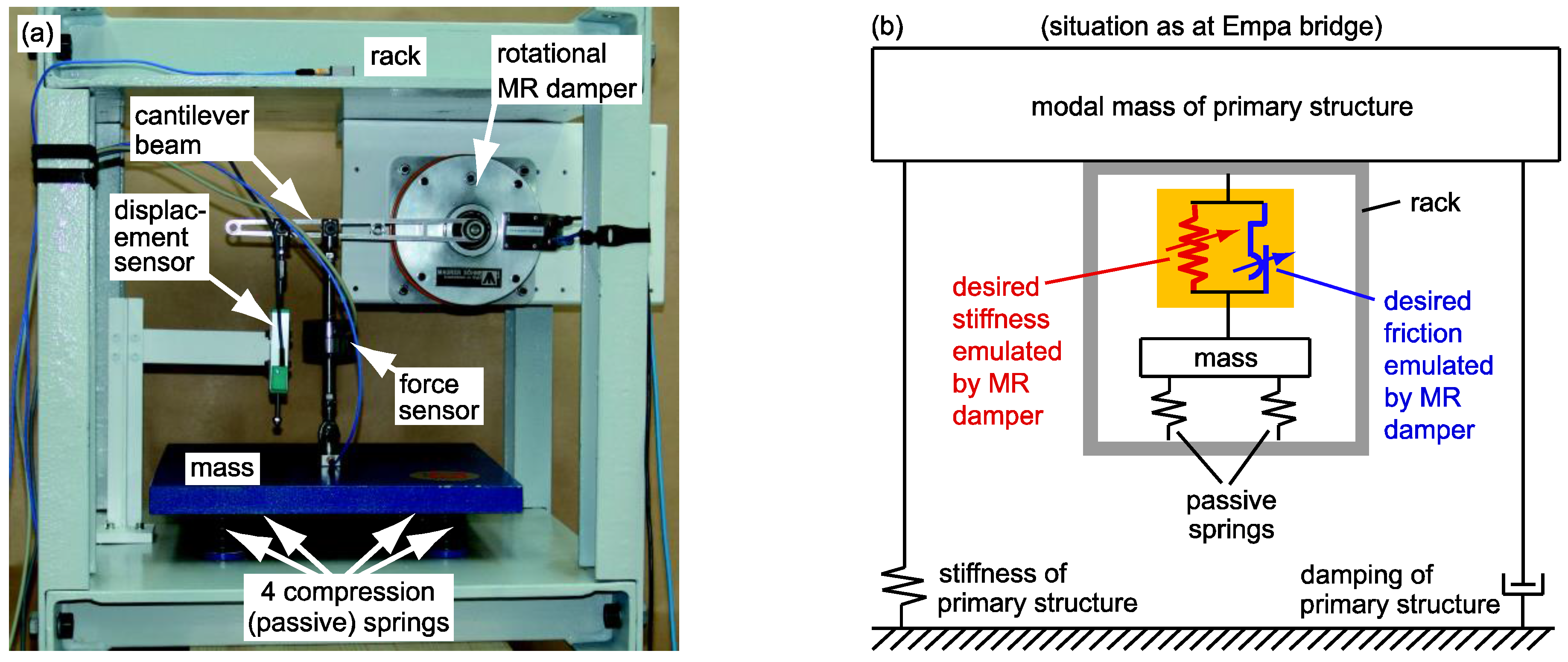
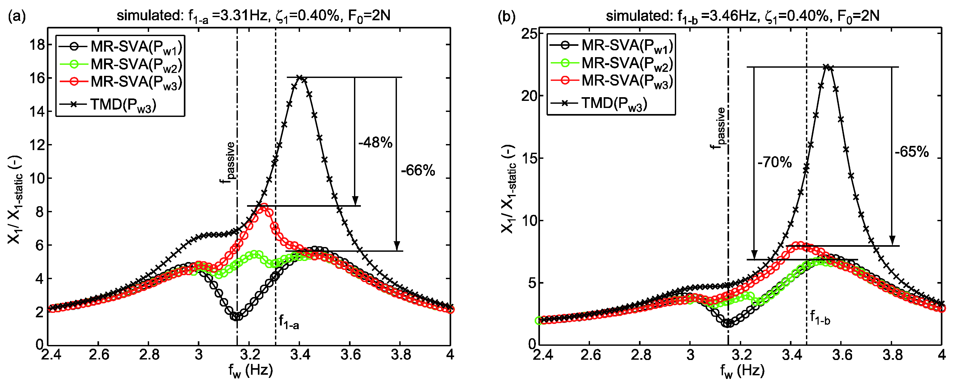
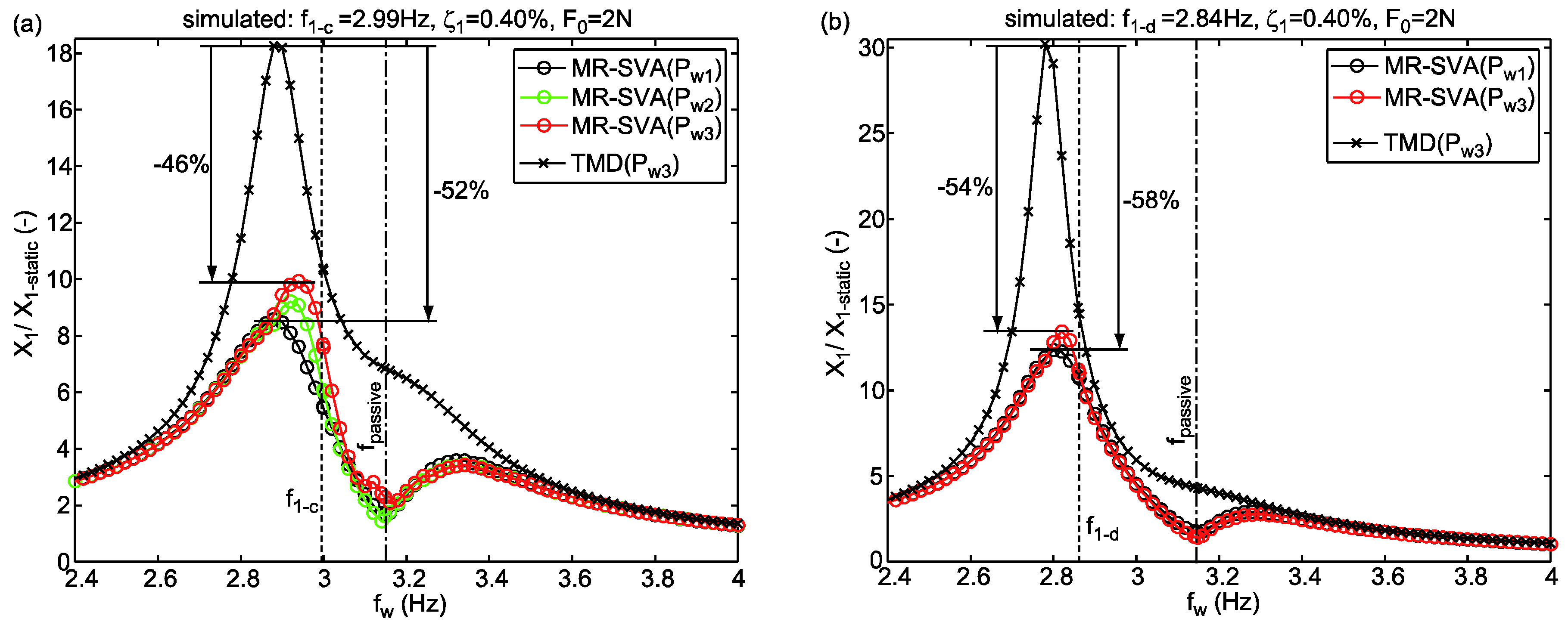
  • The prototype MR-SVA is a mock-up MR-SVA that is designed for a laboratory scale bridge which explains that m 2 and m 1 are small while f p a s s i v e and f 1 are high compared to values of real mass dampers in big structures. Detailed information on the mock-up MR-SVA and the laboratory scale bridge is available in Section 5.1.
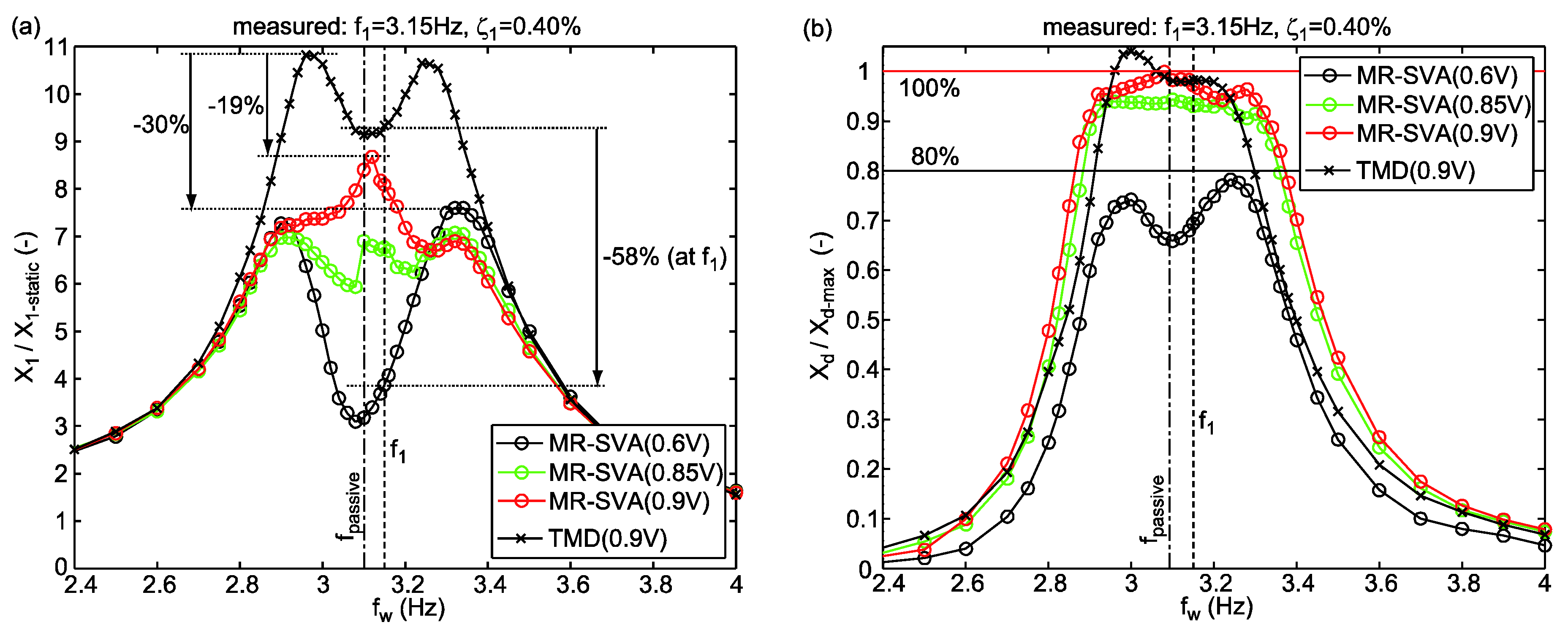
  • The experimental validation of the prototype MR-SVA is performed with a suboptimally tuned f p a s s i v e as the passive mass spring packet of the MR-SVA was originally designed to assess the semi-active TMD concept of the Volgograd Bridge, Russia [2,3,18,21], which required to design f p a s s i v e according to the design of TMDs for minimum structural displacement [6], i.e., f p a s s i v e = f 1 / ( 1 + m 2 / m 1 ) .
  • The residual force of the MR damper of the mock-up MR-SVA varies due to remanent magnetization effects within approx. 2 N and 4 N [18,21,35]; for the simulation the constant residual force F 0 = 2 N is assumed (Table 1).

4.3. Levels of Excitation
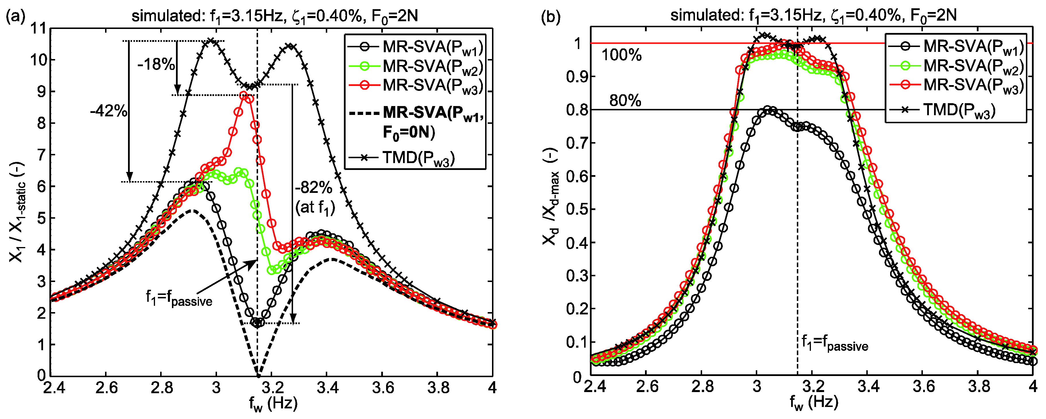
Due to the adaptive damping control approach described in Equations (5)–(9) that aims at minimizing the damping of the MR-SVA if the actual relative motion amplitude X d is not in the vicinity of its maximum tolerable value X d m a x the performance (Equation (16)) of the MR-SVA depends on X d and, as a result, on the amplitude P w of the harmonic excitation force p w = P w s i n ( 2   π   f w   t ) . To demonstrate how the performance (Equation (16)) of MR-SVA depends on P w the MR-SVA is assessed for the following levels of excitation:
  • Maximum excitation P w 3 : The maximum excitation force amplitude P w 3 evokes m a x ( X d ) = X d m a x whereby the desired damping of the MR-SVA is equal to its nominal value c d e s n o m i n a l . For higher levels of excitation, i.e., P w > P w 3 , the normalized displacement response given by Equation (16) does not change since the damping gain γ = 1 for X d > X d m a x does not change the desired damping, see Equation (9).
  • Excitation P w 1 : The excitation force amplitude P w 1 results in m a x ( X d ) = X d l i m whereby the desired damping of the MR-SVA is equal to its minimum value γ m i n   c d e s n o m i n a l . For lower levels of excitation, i.e., P w < P w 1 , the normalized displacement response given by Equation (16) does not change as the damping gain γ = γ m i n for X d < X d l i m is constant, see Equation (9).
  • Excitation P w 2 : The excitation force amplitude P w 2 is selected to be slightly smaller than the worst-case excitation P w 3 , i.e., P w 2 = P w 1 + 0.8 ( P w 3 P w 1 ) , to show the significant vibration reduction improvement when the excitation is approx. 80% to 90% of worst case excitation P w 3 .

4.4. Benchmark

The normalized displacement response (Equation (16)) of the structure with MR-SVA needs to be compared to a benchmark damper in order to quantify the vibration reduction improvements due to the MR-SVA. The benchmark damper chosen here is the passive TMD because it is the most often installed mass damper type and widely known although passive TMDs are not only used to mitigate tonal vibrations but also vibrations due to broadband excitation. The TMD natural frequency and damping are designed for minimum structural displacement response according to Den Hartog [6]. The comparison of the performance of the MR-SVA with that of the TMD is valid because the nominal desired damping, see Equation (5), of the MR-SVA is equal that of the TMD.

4.5. Dynamic Simulation

The coupled equations of motion of the primary structure with MR-SVA including the entire control code
m 1   x ¨ 1 + 2   ζ 1   m 1   ( 2   π   f 1 )   x ˙ 1 + k 1   x 1 + k p a s s i v e ( x 1 x 2 ) = p w f m r a c t
and
m 2   x ¨ 2 + k p a s s i v e   ( x 2 x 1 ) = f m r a c t
are programmed in Matlab/Simulink® (MathWorks, Natick, MA, USA) and solved in the time domain using the solver ode45 (Dormand/Prince) at variable step size with maximum step size of 1 ms and 1 × 10⁻³ relative tolerance. The computation time is selected to ensure steady state condition from which (16) is determined. The control code is computed with γ m i n = 0 and X d l i m / X d m a x = 0.8 to maximize the advantageous effect of the minimized damping of the MR-SVA. The model of the actual MR damper force, see Equation (12), is computed with F 0 = 2 N. Thus, despite the minimized desired damping of the MR-SVA for X d < X d l i m the MR-SVA generates (undesired) damping due to the residual force F 0 = 2 N.

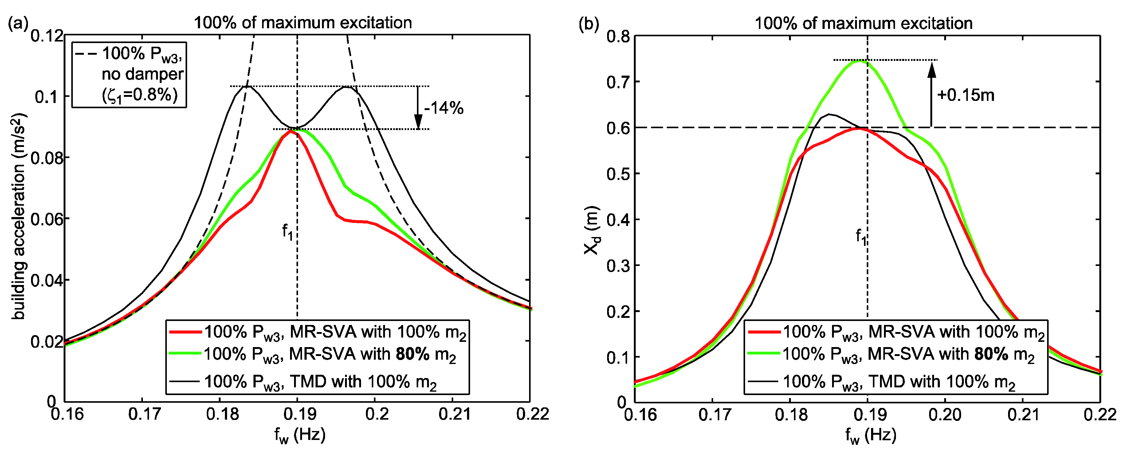
4.6. Numerical Results

The steady state normalized structural displacement amplitudes due to the MR-SVA as function of the excitation frequency and the three considered excitation force amplitudes P w 1 , P w 2 and P w 3 are depicted in Figure 4a, the associated relative motion amplitudes of the absorber mass are shown in Figure 4b, the desired corrected stiffness coefficients are plotted in Figure 5a and the desired viscous damper coefficients accompanied by their equivalent (actual) values are portrayed in Figure 5b. For the following discussion of the simulation data it must be considered that the normalized displacement response due to the TMD does not depend on the level of excitation because of the linearity of the TMD:
  • X d = X d m a x : If the damping of the MR-SVA cannot be reduced by the adaptive nonlinear damping control approach Equations (5)–(9) because the relative motion amplitude X d of the damper mass is equal to X d m a x the normalized displacement X 1 / X 1 s t a t i c due to the MR-SVA is equal to that of the passive TMD; this occurs at f w equal to the natural frequency of the TMD, i.e., f 1 / ( 1 + m 2 / m 1 ) , since then the frequency tunings and—because of X d = X d m a x —also the damping tunings of the TMD and MR-SVA are the same.
  • X d < X d m a x : If the damping of the MR-SVA can be reduced by the adaptive nonlinear damping control approach Equations (5)–(9) due to X d < X d m a x the MR-SVA leads to significantly smaller normalized displacements than the passive TMD because
    • the reduced damping augments X d and thereby increases the amplitude of the MR-SVA stiffness force, and
    • the frequency control f c o n t r o l = f w generates the targeted phase shift of 180 degrees between the MR-SVA stiffness force and the excitation force,
    which both enhance the compensation of the excitation force.
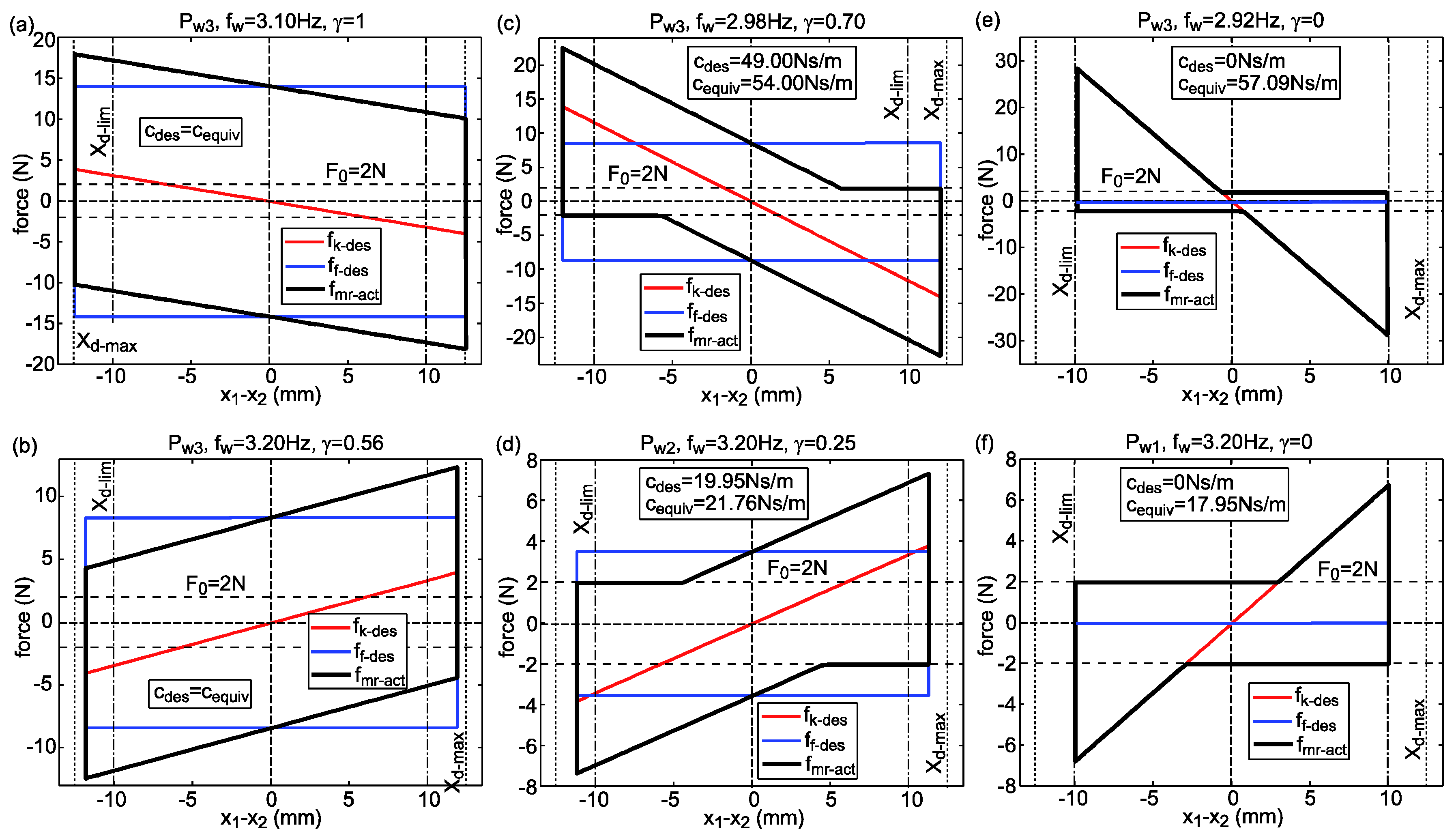
  • The normalized displacement response due to the MR-SVA with F 0 = 2 N and for P w 1 shows two maxima at approx. 2.9 Hz and 3.4 Hz because the actual, i.e., energy equivalent viscous damping coefficient is greater than its desired counterpart at these frequencies which diminishes the stiffness force amplitude of the MR-SVA and, as a result, lowers the compensation of the disturbing force.
  • The simulation of the MR-SVA with negligible small residual force ( F 0 = 0 N) of the MR damper representing an ideal semi-active control force range cancels the oscillations of the primary structure at f w = f 1 since then the MR-SVA precisely emulates the behaviour of the undamped dynamic vibration absorber. For excitation frequencies f w f 1 the MR-SVA cannot generate the behaviour of the undamped dynamic vibration absorber because the stiffness emulation by the MR damper force to generate the frequency control of the MR-SVA can only be realized in combination with a dissipative force whereby undesired damping is generated. Only with active vibration absorbers it is possible to emulate the behaviour of the undamped dynamic vibration absorber for any disturbing frequency [31].
The fact that the emulations of desired stiffness and damping forces by semi-active control devices are—in general—coupled which necessitates prioritizing either precise stiffness emulation or precise damping emulation in case of semi-active devices is familiarized by the force displacement trajectories depicted in Figure 6. As long as the desired semi-active control force is not constrained by the residual force or the semi-active restriction of the semi-active control device the equivalent (actual) viscous damping coefficient c e q u i v is equal to its desired counterpart c d e s (Figure 6a,b). For the MR-SVA this is the case when f w is in the vicinity of f 1 because this yields small desired stiffness coefficients and when c d e s is not too small due to not too small damping gains γ which occurs at rather high levels of excitation. However, in case of larger differences between f w and f 1 , which trigger greater desired stiffness coefficients, and if X d is far smaller than X d m a x , which results in small c d e s due to small γ , the desired semi-active control force is partially constrained by clipping and the residual force (Figure 6c–f). Due to the stiffness correction method (Equation (14)) that generates k e q u i v = k d e s also when clipping and F 0 constrain f m r d e s the equivalent (actual) viscous damping coefficient c e q u i v is bigger than c d e s . For the special case of zero desired damping the stiffness correction method (Equation (14)) outputs k ^ d e s = 2   k d e s (Figure 5a shows this case for P w 1 ). The emulation of a pure stiffness force in semi-active devices then ends up in so-called resetting stiffness (Figure 6e,f) [38]. The resulting equivalent stiffness is 50% of k ^ d e s whereby k e q u i v = k d e s is achieved which generates the targeted precise frequency control (Equation (2)). The actual energy dissipation is then given by the two triangular shaped areas from which c e q u i v is computed which obviously is far bigger than c d e s = 0.
The performance criterion (Equation (16)) is also computed when the modal mass of the primary structure is changed so that the associated eigenfrequencies are changed by +5% ( f 1 a ), +10% ( f 1 b ), −5% ( f 1 c ) and −10% ( f 1 d ) compared to f 1 while the mass spring packet of the MR-SVA and thereby its natural passive frequency f p a s s i v e remain unchanged. These simulations therefore assess the MR-SVA when de-tuning between the eigenfrequency of the primary structure and f p a s s i v e is present (Table 1). As observed from Figure 7a,b and Figure 8a,b the MR-SVA improves the maximum normalized displacement response of the primary by 48% to 70% compared to the TMD. The differences between the displacement response curves of the MR-SVA due to different levels of excitation are not that pronounced as for the case without de-tuning that is portrayed in Figure 4 due to the generation of undesired damping in the MR-SVA at the large frequency differences between f p a s s i v e and the eigenfrequencies f 1 a , f 1 b , f 1 c and f 1 d . In case of the simulation for the structure with f 1 d the differences are so small that the displacement response curve due to P w 2 is omitted in Figure 8b.

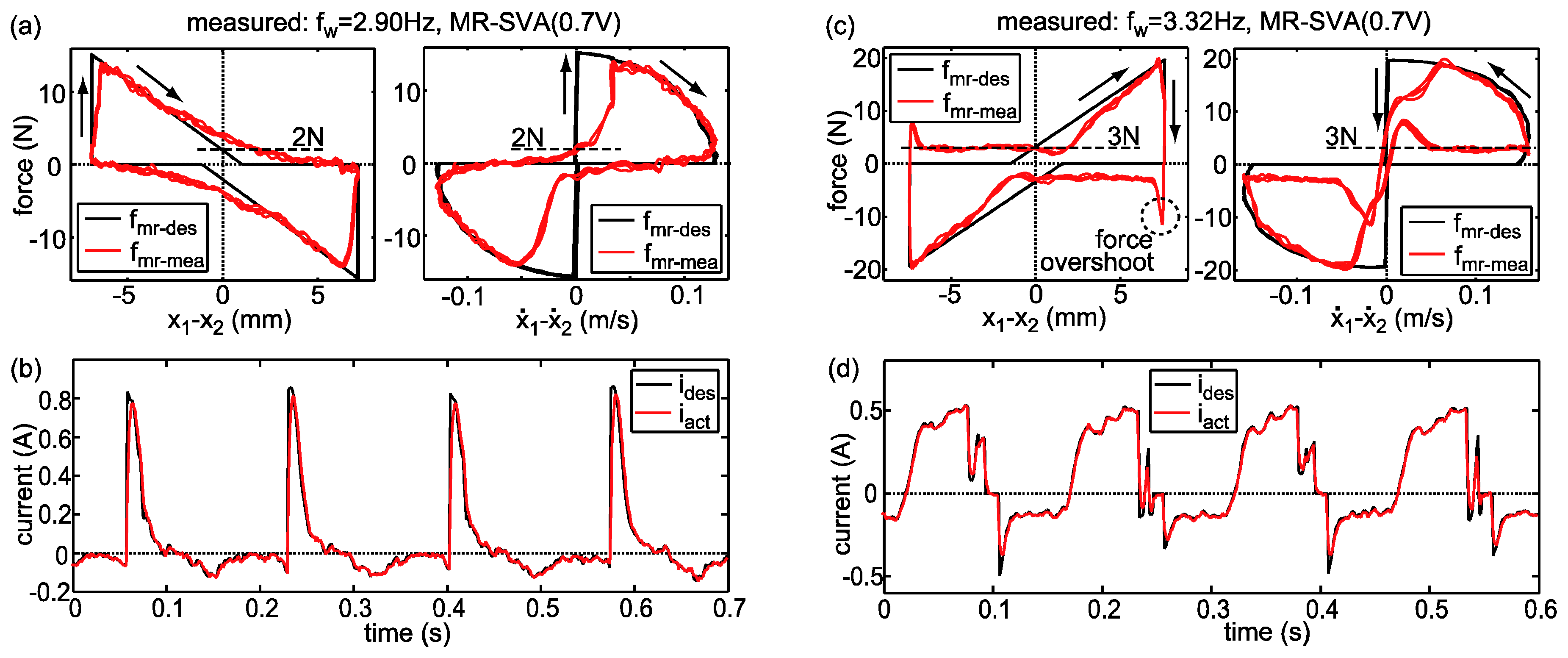
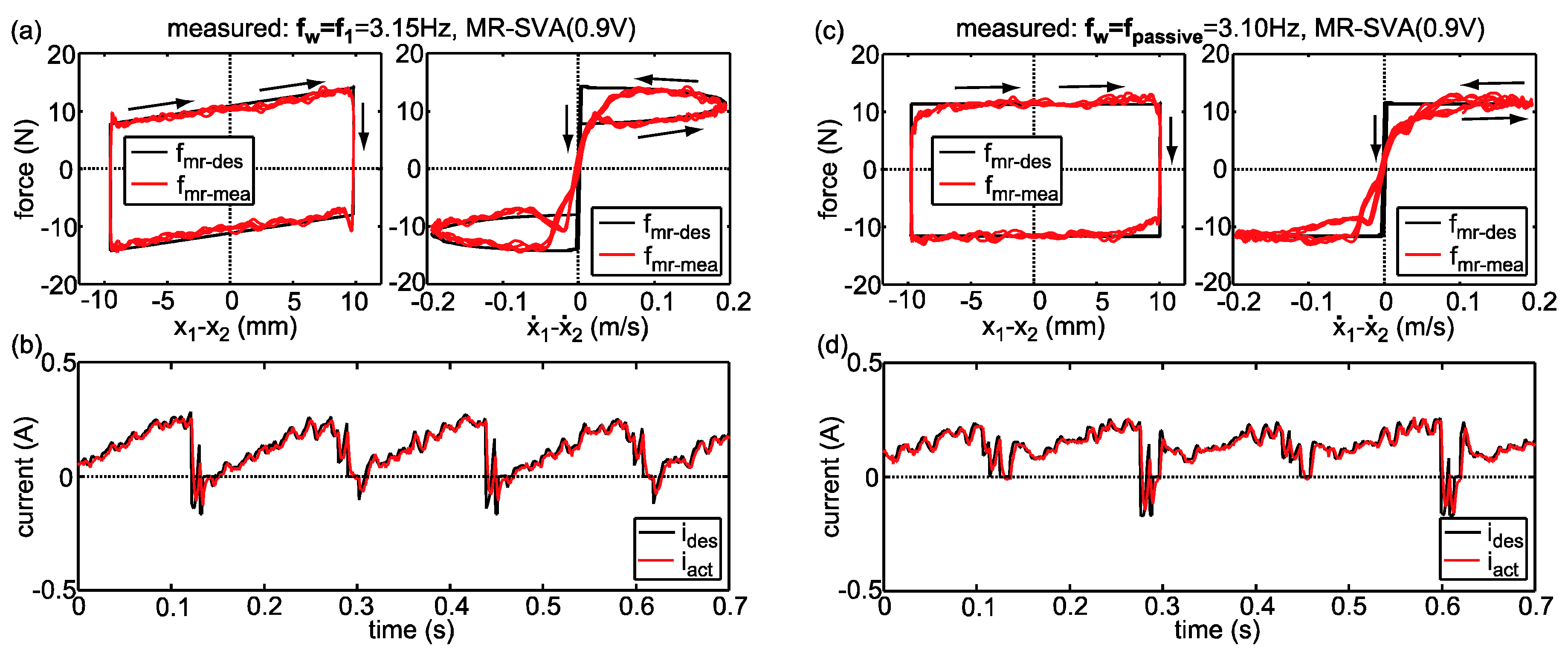
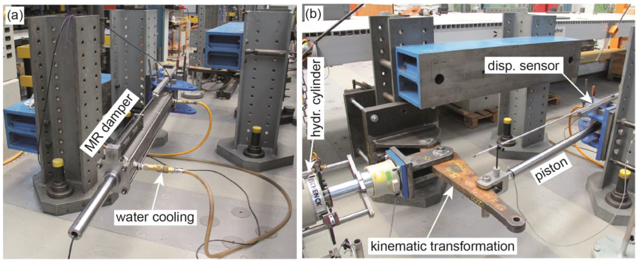
5. Experimental Validation
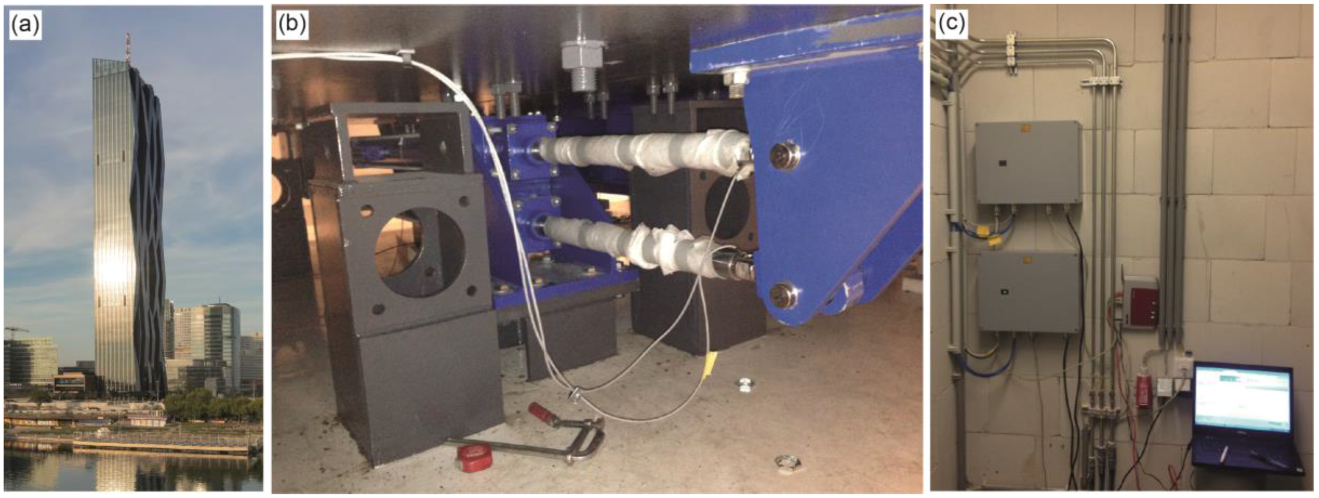
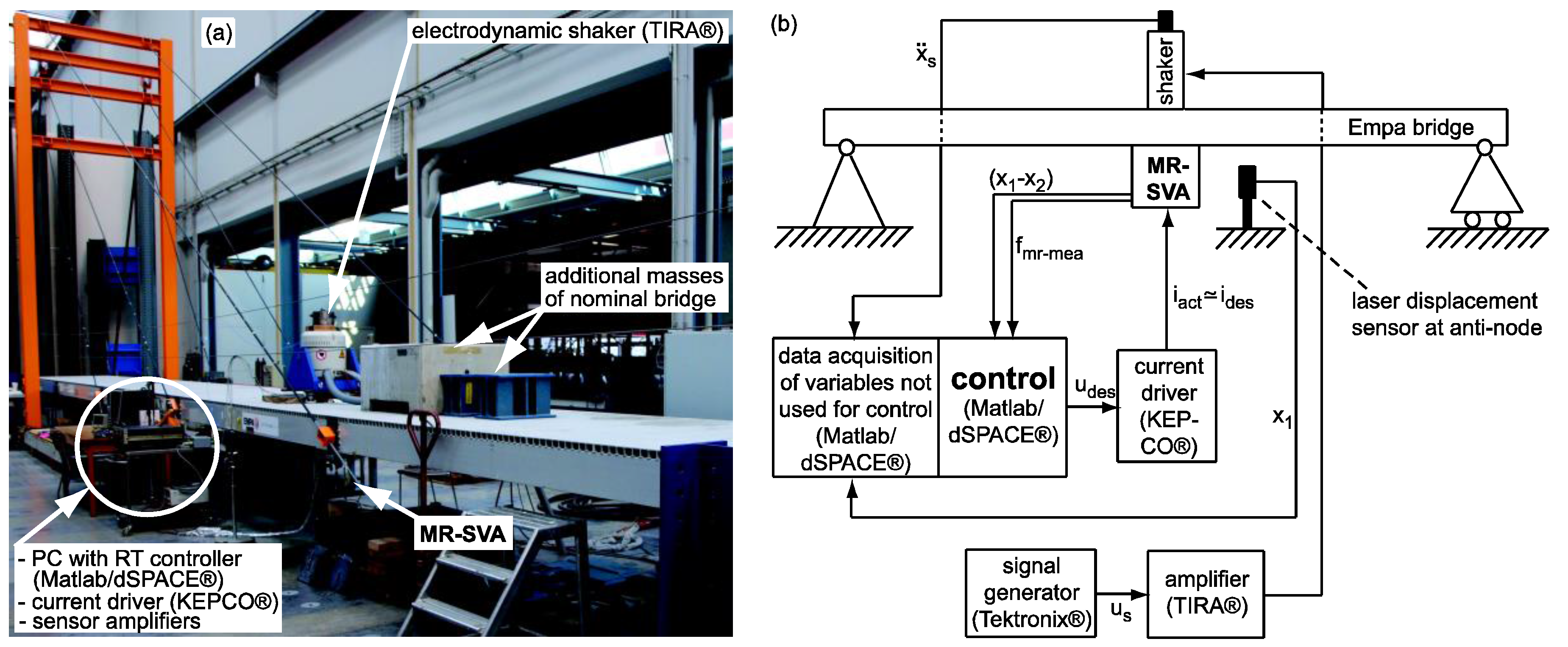
5.1. Test Set-Up

The MR-SVA was experimentally validated in 2012 on a laboratory scale cable-stayed bridge with main span of 15.6 m. Figure 9a shows a photograph of this bridge that was located in the testing laboratory of the Structural Engineering Research Laboratory of Empa, Swiss Federal Laboratories for Materials Science and Technology, Dübendorf, Switzerland. Steel and concrete masses were placed on the bridge deck to realize the properties of the nominal bridge. By changing the masses lighter and heavier bridge versions could be realized. The modal masses m 1 of the first vertical bending mode of the nominal, lighter and heavier bridge versions were experimentally identified by mode shape measurements [18]. The according eigenfrequencies were identified from the transfer function between bridge response and shaker force while the damping ratios were derived from free decay responses due to resonant excitation [18]. The modal properties of all bridge versions are given in Table 1.
The control algorithm was programmed in Matlab/Simulink® and Matlab/dSPACE® was used as real-time controller running at 1000 Hz sampling frequency (Figure 9b). A potentiometric displacement sensor was used to measure the actual relative motion x 1 x 2 of the absorber mass m 2 which is identical with the displacement of the semi-active control device, i.e., the rod of the rotational MR damper [39,40] (Figure 10). The desired semi-active control force (Equation (11)) can be computed in real-time using the measured collocated displacement only (Figure 9b). The response X 1 of the bridge was measured by a laser triangulation sensor at anti-node position where also the shaker that was placed on top of the bridge deck and the MR-SVA that was bolted to the bridge deck from underneath were located. The excitation force of the shaker was derived from the measured acceleration x ¨ s of the shaker mass m s .
The MR damper of the prototype MR-SVA was designed for the expected maximum control forces in rotational form whose functioning is well described in [39,40]. The field dependent yield force of this MR damper is given by the following force current pairs
i = [ 0 ,   0.10 ,   0.15 ,   0.20 ,   0.30 ,   0.40 ,   0.50 ,   0.60 ,   0.70 ,   0.80 ,   1.0 ,   1.2 ,   1.5 ,   2.0 ]   A f = [ ~ 3 ,   8.7 ,   13.5 ,   20.8 ,   40.5 ,   60.1 ,   50.5 ,   99.2 ,   116 ,   132 ,   158 ,   181 ,   210 ,   240 ]   N ,
which were identified from tests using a hydraulic cylinder that imposed a sinusoidal displacement in the cantilever beam of the MR damper at the same position on the cantilever beam as used later in the MR-SVA (where the load cell is attached in Figure 10a). The identified viscous coefficient is hardly current dependent and negligible small.

5.2. Force Tracking Control Scheme

The desired semi-active control force (Equation (11)) is the desired force to be tracked in real-time by the MR damper. In order to realize precise force tracking to realize precise frequency control of the MR-SVA the force tracking task is solved by a combined feed forward/feedback force tracking control scheme [36] (Figure 11). The feed forward relies on an inverted Bingham model of the MR damper. The input states of the feed forward are the desired semi-active control force (Equation (11)) and the actual collocated motion x 1 x 2 of the MR damper from which the collocated velocity x ˙ 1 x ˙ 2 is derived by numerical differentiation in the code. The output of the feed forward is the estimated MR damper current i e s t
i e s t = f u n c t i o n ( f m r d e s , x 1 x 2 , x ˙ 1 x ˙ 2 ) .
The application of i e s t to the MR damper would end up in imprecise force tracking due all effects that are not described by the Bingham model and therefore are not included in the inverse model of the feed forward. Besides others these effects are magnetization and demagnetization dynamics and the pre-yield behaviour of the MR damper force [18,35]. In order to compensate for these effects that are not taken into account within the feed forward the force tracking control scheme is enriched by a feedback correction of the desired current based on the measured MR damper force f m r m e a . As the inverse MR damper model of the feed forward linearizes the controlled plant a linear feedback consisting of a parallel proportional integral (PI) controller is designed.
The PI feedback corrects the estimated current i e s t by the correction current i c o r at time instant t j ,
i c o r ( t j ) = k P   e a ( t j ) + k I   e I ( t j ) ,
where k P denotes the proportional feedback gain, e a ( t j ) is the actual error at time instant t j , k I is the integral feedback gain and e I ( t j ) is the integral error. e a ( t j ) is computed from the absolute values of f m r d e s and f m r m e a if the actual MR damper velocity is larger than the velocity threshold x ˙ m i n
e a ( t j ) = { | f m r d e s ( t j ) | | f m r m e a ( t j ) | : | x ˙ 1 ( t j ) x ˙ 2 ( t j ) | x ˙ m i n 0 : | x ˙ 1 ( t j ) x ˙ 2 ( t j ) | < x ˙ m i n .
The fact that the actual error e a ( t j ) must be determined based on the absolute force values due to the semi-active restriction of the MR damper force is familiarized by the following example. f m r d e s ( t j ) = 20 N and f m r m e a ( t j ) = 19 N lead to e a ( t j ) = 1 N which yields i c o r ( t j + 1 ) > 0 and thereby i d e s ( t j + 1 ) > i d e s ( t j ) . The resulting actual MR damper force increases and consequently e a decreases at the next time instant t j + 1 . Hence, the proportional controller reduces the force tracking error for positive desired and actual forces. For f m r d e s ( t j ) = 20   N and f m r m e a ( t j ) = 19   N (Equation (22)) yields again e a ( t j ) = 1 N which evokes i d e s ( t j + 1 ) > i d e s ( t j ) and consequently f m r m e a ( t j + 1 ) is more negative. Thus, also for negative desired and actual forces the formulation of the actual error based on the absolute force values reduces the force tracking error. However, if the actual error e a ( t j ) was calculated in the classical way, i.e., e a ( t j ) = f m r d e s ( t j ) f m r m e a ( t j ) , f m r d e s ( t j ) = 20   N and f m r m e a ( t j ) = 19   N would lead to e a ( t j ) = 1   N whereby i c o r ( t j + 1 ) < 0 would become negative and i d e s ( t j + 1 ) < i d e s ( t j ) would be reduced. As a result, f m r m e a ( t j + 1 ) would become less negative and the force tracking error would increase. The actual error is reset if the desired force changes its sign, i.e., if | x ˙ 1 ( t j ) x ˙ 2 ( t j ) | < x ˙ m i n , since force tracking is not possible when f m r d e s is constrained by the residual force of the MR damper.
The actual integral error with anti-reset windup (ARW) e I A R W ( t j ) is the sum of the actual error e a ( t j ) and the integral error of the previous time instant t j 1 if i d e s is not constrained by the maximum or minimum current values i m a x and i m i n of the MR damper; otherwise, e I ( t j ) is set to its previous value:
e I A R W ( t j ) = { e a ( t j ) + e I A R W ( t j 1 ) : i m i n < i d e s < i m a x e I A R W ( t j 1 ) : i d e s = i m i n e I A R W ( t j 1 ) : i d e s = i m a x
The ARW is mandatory to prevent that the integral error “winds up”, i.e., becomes larger and larger, even though maximum or minimum current constraints are reached. As for the proportional controller the integral controller is reset when the actual MR damper velocity is smaller than x ˙ m i n :
e I ( t j ) = { e I A R W ( t j ) : | x ˙ 1 ( t j ) x ˙ 2 ( t j ) | x ˙ m i n 0 : | x ˙ 1 ( t j ) x ˙ 2 ( t j ) | < x ˙ m i n
The desired current i d e s ( t j ) is the constrained sum of i e s t ( t j ) and i c o r ( t j ) ,
i d e s ( t j ) = { i e s t ( t j ) + i c o r ( t j ) : i m i n < i e s t ( t j ) + i c o r ( t j ) < i m a x i m i n : i e s t ( t j ) + i c o r ( t j ) i m i n i m a x : i e s t ( t j ) + i c o r ( t j ) i m a x ,
where i m a x = 3.5 A prevents the MR damper coil isolation from melting and i m i n = ࢤ0.6 A (negative value for current reversal) is used to produce current reversal by the PI-feedback to reduce remanent magnetization effects and thereby improve the force tracking accuracy when the desired semi-active force is in the vicinity of the residual force [2,3,8,16,18,21,35,36]. The current driver of type KEPCO® is used as current driver to obtain accurate current tracking i a c t i d e s (Figure 9b and Figure 11).

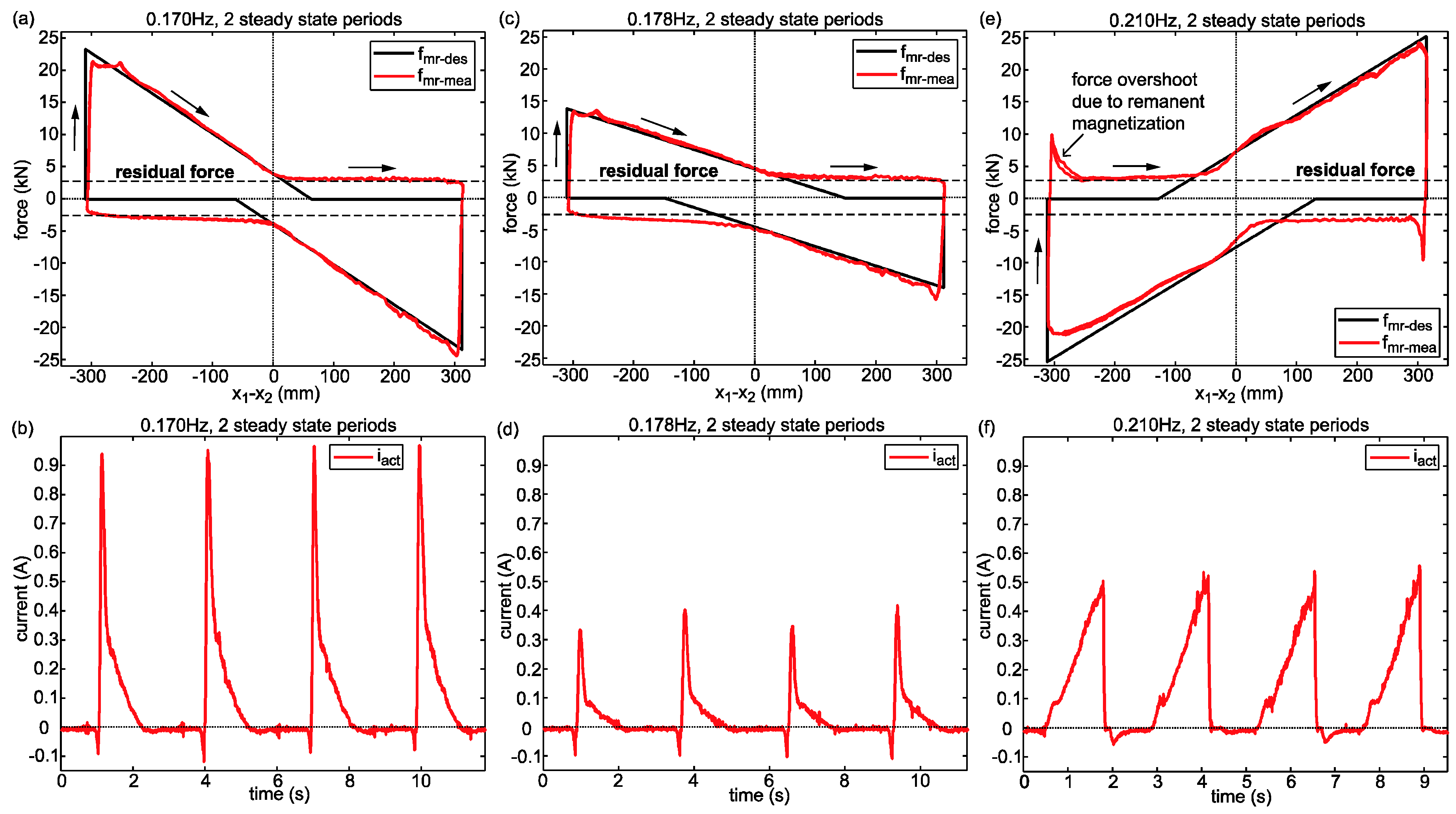
5.3. Experimental Results

The experimental validation of the MR-SVA for the bridge with nominal modal properties is depicted in Figure 12 and Figure 13 analogically with the numerical results portrayed in Figure 4 and Figure 5. The levels of excitation P w 1 , P w 2 and P w 3 considered in the numerical validation approximately correspond to the selected command voltage levels U s = 0.6 V, U s = 0.85 V and U s = 0.9 V of the shaker amplifier (Figure 9b). Comparing the experimental and numerical results two major differences are observed which are discussed in the following.
The experiments of the MR-SVA were made with the spring mass packet that was used to verify the MR damper controlled semi-active TMD concept that was installed in fall 2012 in the Volgograd Bridge for its retrofit [2,3,18,21]. As a result, the natural frequency of the spring mass packet was not designed to be f p a s s i v e = f 1 but f p a s s i v e = f 1 / ( 1 + m 2 / m 1 ) = 3.10 Hz according to the design of TMDs for minimum displacement response [6]. Due to this suboptimal tuning of the passive hardware of the MR-SVA the desired corrected stiffness coefficients become zero at 3.10 Hz and not at f 1 = 3.15 Hz (Figure 13a) whereby the normalized displacement response due to the MR-SVA is also minimized at approx. 3.1 Hz (Figure 12a).
The second main difference is that X 1 / X 1 s t a t i c = 3.04 at is higher than in case of the simulations (1.71). The higher value of the experiments is caused by the higher equivalent (actual) viscous damping coefficient of the real MR damper force because γ m i n = 0.30 was selected for the tests in contrast to γ m i n = 0 for the simulations. This was made because of the slightly higher residual forces of the real MR damper of approx. 3 N that approximately generate the same energy dissipation as when the desired viscous damping coefficient in Equation (8) is computed based on γ m i n = 0.3. The fact that the residual force of real MR dampers is not a constant value but depends on the remanent magnetization at zero current which, in turn, depends on the previous magnetization time history is visible in the measured force displacement trajectories plotted in Figure 14 (large negative and positive stiffness coefficients due to f w < < f p a s s i v e and f w > > f p a s s i v e ) and Figure 15 (small positive stiffness due to f w = f 1 > f p a s s i v e and zero stiffness due to f w = f p a s s i v e ) and is also reported in, e.g., [16,18,35]. The residual force is also affected by the force overshoot in case of positive stiffness emulation. This force overshoot cannot be fully avoided even with current reversal because the previous maximum of the desired force required high current which caused strong magnetization and the time window for current reversal is very short when f m r d e s changes its sign (Figure 14c,d).
The experimental validation of the MR-SVA when de-tuning between f p a s s i v e and the actual eigenfrequency of the primary structure is present is depicted in Figure 16a,b for lighter bridges and in Figure 17a,b for heavier bridges. The modal properties of these bridge versions are the same as considered in the numerical validation (Table 1). As the normalized displacement response curves due to the three selected excitation force amplitudes are very close only the two curves resulting from smallest and largest excitation levels are depicted. The tests demonstrate that the MR-SVA improves the maximum normalized displacement responses compared to the TMD by 43% to 55%. These numbers are slightly smaller than those obtained from the numerical validation (48% to 70%) which is explained by the larger residual force of the real MR damper and larger force tracking errors when large positive (lighter bridges) and large negative (heavier bridges) stiffness coefficients must be emulated by the MR damper. Nevertheless, the significant improvements between 43% and 55% compared to the TMD demonstrate that the MR-SVA can cope efficiently with considerable levels of de-tuning.

6. MR-SVA of Danube City Tower in Vienna

6.1. Project Description

The Danube City Tower in Vienna, Austria, was opened in February 2014 and is the tallest building (250 m) in Austria (Figure 18a). The wind engineering assessment pointed out that the first bending mode in the weak direction of the building with a modal mass of 40,000 metric tonnes and a nominal eigenfrequency of f 1 n o m i n a l = 0.19 Hz requires to be mitigated by a pendulum damper in order to guarantee acceptable low structural accelerations. Investigations of the structural consultant showed that the eigenfrequency of the first bending mode might change by ±10% due to temperature effects and time-varying life loads. Therefore, the concept of the MR-SVA was selected since it can compensate for changes in the eigenfrequency of the Danube City Tower due to its real-time frequency and damping controls [41]. In addition, the adaptive damping control approach of the MR-SVA leads to significantly reduced structural accelerations during wind excitation, i.e., at service load conditions, compared to the passive TMD while it generates disproportionally increased damping during maximum excitation of the Danube City Tower due to earthquakes and thereby guarantees that the actual relative motion amplitude X d does not become larger than its specified maximum X d m a x = 0.6 m (absolute value). In order to augment the safety against impacts of the pendulum mass of 300 metric tonnes into the building walls the adaptive damping gain γ was programmed in the code to disproportionally (quadratic function) increase as function of X d also for X d > X d m a x in contrast to the design proposed by Equation (9) where γ = 1 for X d > X d m a x . As final safety measure against destructive pendulum mass impacts passive shock impact dampers were installed as commonly made for pendulum dampers in tall buildings. The frequency and damping controls are produced by the control forces of two long-stroke MR dampers that are connected to the pendulum mass from underneath (Figure 18b). Both control loops are completely independent, i.e., two independent real-time controllers and two independent displacement sensors with amplifiers were installed to get redundancy (Figure 18c). A water cooling system is included in both MR dampers to prevent the MR dampers from overheating due to large energy dissipation during operation (Figure 19a).

6.2. Hybrid Testing

The control algorithm and the control force tracking accuracy were checked by hybrid testing at Empa, Swiss Federal Laboratories for Materials Science and Technology, Dübendorf, Switzerland, where the MR dampers were operated by a hydraulic cylinder as if the MR dampers were connected to the swaying pendulum mass. A kinematic transformation was used to amplify the displacement of the hydraulic cylinder to perform the hybrid tests at realistic displacement amplitudes of the MR dampers of approx. ±0.3 m (Figure 19b). The water cooling system was running as it is operated in the MR-SVA in the Danube City Tower in order to perform the hybrid tests under exact same conditions as when the MR-SVA is in operation in the Danube City Tower. The testing frequencies comprised the frequencies of the guaranteed frequency control range from 0.17 Hz to 0.21 Hz corresponding to the maximum variations of ±10% of the nominal eigenfrequency of 0.19 Hz. Figure 20a shows that the testing displacement included fairly fast transients whereby the control algorithm was also checked in terms of real-time frequency and amplitude estimations. From the steady state response of the measured MR damper force f m r m e a (Figure 20b) the equivalent stiffness coefficient (Figure 20c) and equivalent viscous damping coefficient (Figure 20d) were determined by post-processing of the test data. As explained in Section 3.7, for maximum vibration reduction in the primary structure the stiffness correction method described in Equation (14) should be computed in the control code with F 0 = 0 N for maximum vibration reduction with the MR-SVA despite the real residual force is not zero. As seen from Figure 21a–c that show three selected force tracking results during steady state conditions the residual force of one MR damper is approx. 2.5 kN which is fairly small considering the maximum force of approx. 45 kN. Due to the computation of Equation (14) with F 0 = 0 N the corrected desired stiffness k ^ d e s does not compensate for the stiffness loss due to the real residual force but only for the stiffness loss due to the clipping. Therefore, the equivalent stiffness differs from the desired stiffness at larger differences between f w and f p a s s i v e = f 1 where the stiffness correction method (Equation (14)) is triggered (Figure 20c). The resulting equivalent viscous damping coefficient that is derived from the cycle energy of the measured MR damper force corresponds well to its desired counterpart when the desired semi-active force is not constrained by clipping nor the real residual force and is larger than its desired counterpart if these control force constraints are present, which generate additional undesired damping, due to larger differences between f w and f p a s s i v e = f 1 .

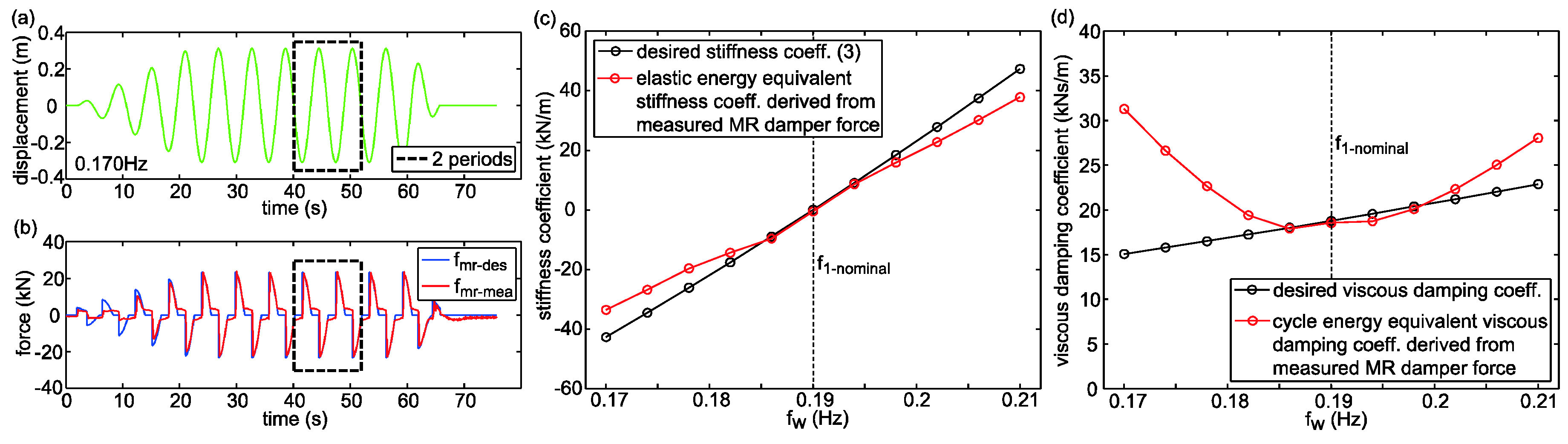
6.3. Accurate Force Tracking Control within 1 Day

Figure 21 depicts the desired semi-active control force and the measured MR damper force as function of the collocated displacement for two selected disturbing frequencies lower than the nominal eigenfrequency whereby negative stiffness is emulated and for one selected disturbing frequency higher than the nominal eigenfrequency which evokes positive desired stiffness. These precise force tracking results were obtained by, first, performing MR damper characterization tests at constant current and 0.19 Hz. The test data were then used to derive the inverse MR damper model of the feed forward (Figure 11). After that the feedback gain k P was tuned by trial and error to get satisfactory force tracking results and, subsequently, k I was tuned to remove steady state force tracking errors. Then, the velocity threshold x ˙ m i n was selected and k P and k I were re-tuned to minimize the force tracking errors. Finally, the force tracking tests at eleven disturbing frequencies were performed according to the procedure shown in Figure 20a,b and evaluated in terms of equivalent stiffness and damping coefficients. All this work was accomplished within 1 working day which proofs that the combined feed forward/feedback control force tracking scheme described in Section 5.2 and more in detail in [36] is simple to adopt and tune, generates precise control force tracking and is robust against changes in frequency since the feed forward model relies on characterization tests at one frequency only.

6.4. MR-SVA with Reduced Mass

The pendulum mass may become very large, i.e., up to 2000 metric tonnes which is then split into two pendulum masses, and therefore expensive in case of tall buildings with extremely large modal masses. In addition, square meter prizes in tall buildings may be exceedingly high whereby the goal of the building owner is rent and sell every square meter possible. Consequently, a key issue for the mass damper designers is to minimize their required space. It is a need to develop mass damper concepts that lead to the same vibration reduction in the building as common passive TMDs but with less space demand as, e.g., folded pendulum TMDs that require less installation height or with smaller tuned mass which can be realized by the MR-SVA concept as described hereafter.
The case study of the MR-SVA with only 80% of the nominal tuned mass of 300 metric tonnes is performed with the modal properties of the Danube City Tower, i.e., m 1 = 40,000 metric tonnes, f 1 = 0.19 Hz and ζ 1 = 0.8%, and for minimized acceleration response of the primary structure as commonly targeted for buildings [7]. The simulated acceleration response of the primary structure is determined for the passive TMD with m 2 = 300 metric tonnes, for the MR-SVA with m 2 = 300 metric tonnes as installed in the Danube City Tower, and for the MR-SVA with 80% of m 2 , i.e., with 240 metric tonnes (Figure 22a). Similarly to the numerical validation described in Section 4, the excitation force amplitude P w 3 is selected such that m a x ( X d ) of the MR-SVA with the nominal mass m 2 = 300 metric tonnes is equal to the specified maximum of X d m a x = 0.6 m (Figure 22b). The simulations demonstrate that the MR-SVA with a tuned mass of only 240 metric tonnes yields the same maximum acceleration of the primary structure as the MR-SVA with a tuned mass of 300 metric tonnes because X d of the MR-SVA with 240 metric tonnes becomes larger due to the smaller pendulum mass and because the desired damping in the code is decreased by 10%. The drawback is that m a x ( X d ) of the MR-SVA with reduced mass is increased by 0.15 m. However, despite the increased relative motion the MR-SVA with reduced mass does not require more but even less space than the MR-SVA with nominal mass as the following calculation demonstrates. Assuming a height of 3 m and steel as material for the pendulum mass, the length and width of the nominal pendulum mass (300 metric tonnes) become 3.56 m while they become 3.18 m in case of the reduced mass (240 metric tonnes). The reductions in length and width of 3.56 m − 3.18 m = 0.38 m due to the reduction of the pendulum mass by 20% are greater than twice the increase of the relative motion amplitude, i.e., 2 × 0.15 m = 0.30 m. Thus, the MR-SVA with only 80% of the mass of the passive TMD does not only improve the vibration reduction of the primary structure (at least 14%, see Figure 22a and Figure 23a) but also requires less space than the passive TMD with nominal mass. For the sake of completeness the MR-SVA with 80% of mass is also computed for 50% of the worst-case excitation P w 3 (Figure 23a). These results point out that the MR-SVA with 80% of mass also significantly improves the acceleration response of the building compared to the TMD at medium excitation level and the associated relative motion amplitudes are not of concern as they are far below 0.75 m (Figure 23b).

7. Summary and Conclusions

This paper describes the concept of a semi-active vibration absorber based on a real-time controlled MR damper (MR-SVA). The control algorithm is formulated to emulate the behaviour of the undamped dynamic vibration absorber for the actual disturbing frequency as close as the limitation of the relative motion amplitude of the absorber mass and the semi-active restriction of the MR damper force allow minimizing the damping. The numerical and experimental validations of the MR-SVA are performed for harmonic disturbing forces and for different levels of de-tuning between the targeted eigenfrequency of the primary structure and the passive natural frequency of the MR-SVA. The results of both validations demonstrate that the MR-SVA reduces significantly the response of the primary structure compared to the passive TMD for all levels of de-tuning and the resulting relative motion amplitude of the absorber mass is smaller than for the TMD.
As the described control algorithm relies on the precise emulation of a desired stiffness force, which generates the real-time frequency control of the MR-SVA, accompanied by a desired damping force, which controls the relative motion amplitude of the absorber mass, a control force tracking scheme for MR dampers is described that can be programmed and fine-tuned within less a day and leads to precise control force tracking.
Finally, the MR-SVA in pendulum form of the Danube City Tower in Vienna, Austria, is described which is—together with the Axaiski Bridge in Russia—the first structure where the MR-SVA is commercially installed. Simulations of the Danube City Tower with MR-SVA with only 80% of pendulum mass point out that the MR-SVA with reduced mass also significantly improves the vibration reduction compared to the passive TMD and that the associated increased relative motion amplitude of the reduced mass is more than compensated by the reduced dimensions of the pendulum mass. Consequently, the MR-SVA with reduced mass requires less space in the building which is highly preferable from the building owner’s economic point of view.
As stiffness and damping emulations with semi-active dampers are—in general—coupled quantities the presented control algorithm is designed to prioritize the frequency control of the MR-SVA by precise stiffness emulation while—in general—the resulting damping is suboptimal. Therefore, future work has to focus on the development of stiffness and damping correction strategies that improve the damping emulation accuracy while maintaining precise stiffness emulation.

Acknowledgments

The authors gratefully acknowledge the financial supports of MAURER SE, Munich, Germany, and Empa, Swiss Federal Laboratories for Material Science and Technology, Dübendorf, Switzerland.

Author Contributions

Felix Weber developed the control algorithm and the MR-SVA and Hans Distl and Sebastian Fischer designed the MR-SVA. The simulations were made by Felix Weber. The tests including the evaluation of the data were conducted by Felix Weber, Hans Distl and Sebastian Fischer. Felix Weber, Hans Distl, Sebastian Fischer and Christian Braun were concerned with the commercial aspects of the MR-SVA and wrote the paper.

Conflicts of Interest

The authors declare no conflict of interest.

References

  1. Structurae. Volgograd Bridge. Available online: https://structurae.net/structures/volgograd-bridge/videos (accessed on November 2016).
  2. Weber, F.; Distl, H. Real-time controlled tuned mass dampers for Wolgograd Bridge. Beton-Und Stahlbetonbau 2013, 108, 362–372. [Google Scholar] [CrossRef]
  3. Weber, F.; Distl, H.; Maślanka, M. Semi-active TMD Concept for Volgograd Bridge. Top. Dyn. Civ. Struct. 2013, 4, 79–88. [Google Scholar]
  4. Thornton Tomasetti. Taipei 101’s TMD Explained. Available online: https://www.thorntontomasetti.com/taipei-101s-tmd-explained/ (accessed on November 2016).
  5. Holmes, J.D. Wind Loading of Structures, 3rd ed.; CRC Press: Boca Raton, FL, USA, 2015. [Google Scholar]
  6. Den Hartog, J.P. Mechanical Vibrations; McGraw-Hill Book Company: New York, NY, USA; The Maple Press Company: York, PA, USA, 1934. [Google Scholar]
  7. Asami, T.; Nishihara, O. Closed-Form Exact Solution to H Optimization of Dynamic Vibration Absorbers (Application to Different Transfer Functions and Damping Systems). Tech. Briefs J. Vib. Acoust. 2003, 125, 398–411. [Google Scholar] [CrossRef]
  8. Weber, F. Semi-active vibration absorber based on real-time controlled MR damper. Mech. Syst. Signal Process. 2014, 46, 272–288. [Google Scholar] [CrossRef]
  9. Pinkaew, T.; Fujino, Y. Effectiveness of semi-active tuned mass dampers under harmonic excitation. Eng. Struct. 2001, 23, 850–856. [Google Scholar] [CrossRef]
  10. Lin, P.Y.; Chung, L.L.; Loh, C.H. Semiactive control of building structures with semiactive tuned mass damper. Comput. Aided Civ. Infrastruct. Eng. 2005, 20, 35–51. [Google Scholar] [CrossRef]
  11. Cai, C.S.; Wu, W.J.; Araujo, M. Cable vibration control with a TMD-MR damper system: Experimental exploration. J. Struct. Eng. ASCE 2007, 133, 629–637. [Google Scholar] [CrossRef]
  12. Casado, C.M.; Poncela, A.V.; Lorenzana, A. Adaptive Tuned Mass Damper for the Construction of Concrete Piers. Struct. Eng. Int. 2007, 17, 252–255. [Google Scholar] [CrossRef]
  13. Nagarajaiah, S.; Sonmez, E. Structures with semiactive variable stiffness single/multiple tuned mass dampers. J. Struct. Eng. 2007, 133, 67–77. [Google Scholar] [CrossRef]
  14. Kang, J.; Kim, H.-S.; Lee, D.-G. Mitigation of wind response of a tall building using semi-active tuned mass dampers. Struct. Des. Tall Spec. Build. 2011, 20, 552–565. [Google Scholar] [CrossRef]
  15. Weber, F.; Boston, C.; Maślanka, M. Adaptive TMD based on the emulation of positive and negative stiffness with MR damper. Smart Mater. Struct. 2011, 20, 015012. [Google Scholar] [CrossRef]
  16. Zemp, R.; de la Llera, J.C.; Roschke, P. Tall building vibration control using a TM-MR damper assembly: Experimental results and implementation. Earthq. Eng. Struct. Dyn. 2011, 40, 257–271. [Google Scholar] [CrossRef]
  17. Woo, S.S.; Lee, S.H.; Chung, L. Seismic response control of elastic and inelastic structures by using passive and semi-active tuned mass dampers. Smart Struct. Syst. 2011, 8, 239–252. [Google Scholar] [CrossRef]
  18. Weber, F.; Maślanka, M. Frequency and damping adaptation of a TMD with controlled MR damper. Smart Mater. Struct. 2012, 21, 055011. [Google Scholar] [CrossRef]
  19. Chung, L.-L.; Lai, Y.-A.; Yang, C.-S.W.; Lien, K.-H.; Wu, L.-Y. Semi-active tuned mass dampers with phase control. J. Sound Vib. 2013, 332, 3610–3625. [Google Scholar] [CrossRef]
  20. Mishra, S.K.; Gur, S.; Chakraborty, S. An improved tuned mass damper (SMA-TMD) assisted by a shape memory alloy spring. Smart Mater. Struct. 2013, 22, 095016. [Google Scholar] [CrossRef]
  21. Weber, F. Dynamic characteristics of controlled MR-STMDs of Wolgograd Bridge. Smart Mater. Struct. 2013, 22, 095008. [Google Scholar] [CrossRef]
  22. Frahm, H. Devices for Damping Vibrations of Bodies. U.S. Patent 989,958,1911, 30 October 1909. [Google Scholar]
  23. Fang, S.; Liu, S.; Liang, J. The Design of Dynamic Vibration Absorber on the Engine of Fire Smoke Exhausting Robot. Appl. Mech. Mater. 2012, 105–107, 180–184. [Google Scholar] [CrossRef]
  24. Koo, J.H.; Ahmadian, M.; Setareh, M. Experimental robustness analysis of magneto-rheological tuned vibration absorbers subject to mass off-tuning. J. Vib. Acoust. 2006, 128, 126–131. [Google Scholar] [CrossRef]
  25. Chen, Z.; Ma, A.; You, X.; Shi, L. Theoretical Research of the Active-type Dynamic Vibration Absorbers. Adv. Mater. Res. 2011, 255–260, 1820–1824. [Google Scholar] [CrossRef]
  26. Kim, Y.K.; Koo, J.H.; Kim, K.S.; Kim, S.H. Suppressing harmonic vibrations of a miniature cryogenic cooler using an adaptive tunable vibration absorber based on magneto-rheological elastomers. Rev. Sci. Instrum. 2011, 82, 035103. [Google Scholar] [CrossRef] [PubMed]
  27. Kim, S.-M.; Wang, S.; Brennan, M.J. Optimal and robust modal control of a flexible structure using an active dynamic vibration absorber. Smart Mater. Struct. 2011, 20, 045003. [Google Scholar] [CrossRef]
  28. Liao, G.J.; Gong, X.L.; Kang, C.J.; Xuan, S.H. The design of an active-adaptive tuned vibration absorber based on magnetorheological elastomer and its vibration attenuation performance. Smart Mater. Struct. 2011, 20, 075015. [Google Scholar] [CrossRef]
  29. Xu, Z.B.; Gong, X.L.; Chen, X.M. Development of a Mechanical Semi-Active Vibration Absorber. Adv. Vib. Eng. 2011, 10, 229–238. [Google Scholar]
  30. Acar, M.A.; Yilmaz, C. Design of an adaptive-passive dynamic vibration absorber composed of a string-mass system equipped with negative stiffness tension adjusting mechanism. J. Sound Vib. 2013, 332, 231–245. [Google Scholar] [CrossRef]
  31. Weber, F. Optimal semi-active vibration absorber for harmonic excitation based on controlled semi-active damper. Smart Mater. Struct. 2014, 23, 095033. [Google Scholar] [CrossRef]
  32. Weber, F.; Baader, J.; Bitterli, K.; Rufer, P. Actively controlled vibration absorbers for long span belt conveyor bridges. Stahlbau 2015, 84, 246–251. [Google Scholar] [CrossRef]
  33. Weber, F.; Boston, C. Energy Based Optimization of Viscous-Friction Dampers on Cables. Smart Mater. Struct. 2010, 19, 045025. [Google Scholar] [CrossRef]
  34. Weber, F.; Boston, C. Clipped viscous damping with negative stiffness for semi-active cable damping. Smart Mater. Struct. 2011, 20, 045007. [Google Scholar] [CrossRef]
  35. Weber, F.; Maślanka, M. Precise Stiffness and Damping Emulation with MR Dampers and its Application to Semi-active Tuned Mass Dampers of Wolgograd Bridge. Smart Mater. Struct. 2014, 23, 015019. [Google Scholar] [CrossRef]
  36. Weber, F. Robust force tracking control scheme for MR dampers. Struct. Control Health Monit. 2015, 22, 1373–1395. [Google Scholar] [CrossRef]
  37. Meirovitch, L. Fundamentals of Vibrations; McGraw-Hill: New York, NY, USA, 2001. [Google Scholar]
  38. Yang, J.; Kim, J.; Agrawal, A. Resetting Semiactive Stiffness Damper for Seismic Response. Control. J. Struct. Eng. 2000, 126, 1427–1433. [Google Scholar] [CrossRef]
  39. Boston, C.; Weber, F.; Guzzella, L. Modeling of a disk-type magnetorheological damper. Smart Mater. Struct. 2010, 19, 045005. [Google Scholar] [CrossRef]
  40. Weber, F. Working Behaviour and Control of Magnetorheological Dampers. In New Trends in Smart Technologies; Boller, C., Janocha, H., Eds.; Fraunhofer Verlag: Saarbrücken, Germany, 2013. [Google Scholar]
  41. Weber, F.; Huber, P.; Distl, H.; Braun, C. Real-time controlled TMD of Danube City Tower. In Proceedings of the CTBUH (Council on Tall Buildings and Urban Habitat) International Conference 2016, Shenzhen, Guangzhou, Hong Kong, China, 16–21 October 2016.
Figure 1. (a) MR-SVA with real-time frequency and damping controls based on the emulations of controllable stiffness and friction forces in the MR damper and (b) equivalent mechanical model.
Actuators 05 00027 g001
Figure 2. (a) Real-time frequency detection; (b) proposed design of adaptive damping gain.
Actuators 05 00027 g002
Figure 3. Desired semi-active control force (a,b) without control force constraints due to | k d e s |   F d e s / X d ; (c,d) with active forces clipped to zero due to | k d e s |   > F d e s / X d and further constrained by F 0 and (e) with corrected stiffness for precise frequency control of MR-SVA.
Actuators 05 00027 g003
Figure 4. Simulated (a) vibration reduction and (b) relative motion amplitude for nominal primary structure.
Actuators 05 00027 g004
Figure 5. Simulated (a) desired corrected stiffness and (b) desired viscous damping coefficient (including damping gain γ ) accompanied by equivalent (actual) viscous damping coefficient.
Actuators 05 00027 g005
Figure 6. Simulated desired semi-active control force and resulting simulated actual MR damper force that is (a,b) not constrained by clipping and F 0 due to small differences between f w and f 1 , (cf) constrained by clipping and F 0 due to larger differences between f w and f 1 and (c,d) non-zero desired damping and (e,f) zero desired damping generating resetting stiffness.
Actuators 05 00027 g006
Figure 7. Simulated vibration reductions of lighter primary structures with (a) f 1 a and (b) f 1 b .
Actuators 05 00027 g007
Figure 8. Simulated vibration reductions of heavier primary structures with (a) f 1 c and (b) f 1 d .
Actuators 05 00027 g008
Figure 9. (a) Photograph and (b) sketch of laboratory scale bridge with prototype MR-SVA, control hardware, measurement hardware and shaker.
Actuators 05 00027 g009
Figure 10. (a) Photograph and (b) sketch of prototype MR-SVA for laboratory scale bridge.
Actuators 05 00027 g010
Figure 11. Force tracking control by model-based feed forward and linear feedback with anti-reset windup.
Actuators 05 00027 g011
Figure 12. Measured (a) vibration reduction and (b) relative motion amplitude for nominal bridge.
Actuators 05 00027 g012
Figure 13. Measured (a) desired corrected stiffness and (b) desired viscous damping coefficient (including damping gain γ ) accompanied by equivalent (actual) viscous damping coefficient.
Actuators 05 00027 g013
Figure 14. Measured force tracking control for (a,b) large negative desired stiffness due to f w < < f p a s s i v e and (c,d) large positive desired stiffness due to f w > > f p a s s i v e .
Actuators 05 00027 g014
Figure 15. Measured force tracking control for (a,b) small positive desired stiffness due to f w = f 1 > f p a s s i v e and (c,d) zero desired stiffness due to f w = f p a s s i v e .
Actuators 05 00027 g015
Figure 16. Measured vibration reductions of lighter bridges with (a) f 1 a and (b) f 1 b .
Actuators 05 00027 g016
Figure 17. Measured vibration reductions of heavier bridges with (a) f 1 c and (b) f 1 d .
Actuators 05 00027 g017
Figure 18. (a) Danube City Tower in Vienna, Austria; (b) MR-SVA of Danube City Tower with two controlled MR dampers and (c) two independent real-time controllers.
Actuators 05 00027 g018
Figure 19. Hybrid testing of MR dampers of Danube City Tower: (a) MR damper with water cooling system and (b) kinematic transformation to perform hybrid tests at realistic displacement amplitudes.
Actuators 05 00027 g019
Figure 20. (a,b) Example of hybrid test; (c) stiffness emulation accuracy with F 0 = 0 N in control code and (d) resulting equivalent (actual) viscous damping coefficient.
Actuators 05 00027 g020
Figure 21. Control force tracking accuracy during two steady state cycles of selected hybrid tests: emulations of (a,b) large negative stiffness due to f w < < f p a s s i v e = f 1 n o m i n a l ; (c,d) medium negative stiffness due to f w < f p a s s i v e = f 1 n o m i n a l and (e,f) large positive stiffness due to f w > > f p a s s i v e = f 1 n o m i n a l .
Actuators 05 00027 g021
Figure 22. Simulated (a) vibration reduction and (b) relative motion amplitude for maximum excitation of primary structure with MR-SVA with nominal and reduced (80%) pendulum masses.
Actuators 05 00027 g022
Figure 23. Simulated (a) vibration reduction and (b) relative motion amplitude for 50% of maximum excitation of primary structure with MR-SVA with nominal and reduced (80%) pendulum masses.
Actuators 05 00027 g023
Table 1. Parameters of prototype MR-SVA, primary structure with nominal and changed eigenfrequencies.
Tuned CaseDe-Tuned Cases
Prototype MR-SVANominal Primary StructureEigenfrequency ChangeEigenfrequencyDampingRatio
f p a s s i v e = 3.15 Hz (simulation) f 1 = 3.15 Hz+5% f 1 a = 3.31 Hz0.52%
f p a s s i v e = 3.10 Hz (tests) m 1 = 1680 kg+10% f 1 b = 3.46 Hz0.51%
m 2 = 26.325 kg k 1 = 658.1 kN/m−5% f 1 c = 2.99 Hz0.48%
F 0 = 2 N (simulation) ζ 1 = 0.40%−10% f 1 d = 2.84 Hz0.49%
F 0 2, …, 4 N (tests)

