
Training, Control and Application of SMA-Based Actuators with Two-Way Shape Memory Effect

1
State Key Laboratory of Mechanics and Control of Mechanical Structures, Nanjing University of Aeronautics and Astronautics, Nanjing 210016, China
2
College of Aerospace Engineering, Nanjing University of Aeronautics and Astronautics (NUAA), Nanjing 210016, China
*
Author to whom correspondence should be addressed.
Actuators 2023, 12(1), 25; https://doi.org/10.3390/act12010025
Submission received: 15 November 2022
/
Revised: 31 December 2022
/
Accepted: 2 January 2023
/
Published: 5 January 2023
(This article belongs to the Special Issue Shape Memory Alloys and Piezoelectric Materials and Their Applications)
Abstract
:Shape memory alloys (SMAs) are widely used in aerospace, automobile, and other fields because of their excellent properties, such as large driving force and large deformation. A training method with a bidirectional memory effect is proposed for SMA actuators. The trained SMA units can be heated and cooled to change their shape (shorten and extend). The trained SMA is used as an actuator to drive the deformation of a structure. Due to the obvious hysteresis characteristics of SMA, a temperature-displacement hysteresis model based on the Preisach model is proposed in order to reduce the influence of hysteresis in the process of structural deformation. The F function method (FFM) is used for Preisach numerical implementation, and a PID control method is used for the precise control of structural deformation. Compared with the PID control method without hysteresis model, this method is superior to the PID control method in response speed and control accuracy. The maximum relative error of three target points in the experiment is 5.45%, which is better than the PID control method without this model. The hysteresis model can be applied to the displacement control of a SMA-based actuator.
1. Introduction
During the development of modern aircraft, their shape design is a compromise that allows them to fly within a range of flight conditions, but the performance in each condition is sub-optimal. To achieve a multi-objective design, adaptive morphing aircrafts are proposed by researchers [1]. Today, there is a wide range of designs for morphing aircrafts that can fulfill different flight conditions. The main types that can be used for the construction of aircraft variants are as follows: planform alteration (span, sweep, and chord), out-of-plane transformation (twist, dihedral, and span-wise bending), and airfoil adjustment (camber and thickness) [2]. In addition, other deformation structures and applications are mainly categorized into aircraft inlet deflections [3], aircraft door sealing plates [4,5], and origami robots [6]. The German Aerospace Center (DLR) proposed a series of structural solutions for adaptive drooping leading edge deformation, using a mechanical link structure to drive the deformation of the seamless flexible skin of the leading edge of the wings [7]. Jinks et al. optimized the design of adaptive shock control bumps (SCB) for transonic wings, and verified the drag reduction performance through wind tunnel tests and simulation calculations [8].
With the continuous progress of research on functional materials, smart materials, such as piezoelectric materials, shape memory alloy materials, magnetostrictive materials, and current variant materials are widely used in fields including aerospace, biomedicine, and mechanical appliances [9]. One of these materials is shape memory alloy (SMA), a functional material with a pseudoelastic effect (PE) and shape memory effect (SME) [10,11,12,13], which is able to have different shapes at high and low temperatures. This special property makes SMAs widely used in a range of technical fields [14,15]. Hao et al., based on the SCBs, proposed a two-dimensional bump structure made of SMAs [16]. The SMA bump is trained to have a flat initial shape with a certain initial strain, which can swell up when thermally activated. Compared with mechanical SCBs, SMA bumps have a simpler and lighter actuator structure. A SMA-based variable geometry chevron thrust reverser sleeve has been designed by the Boeing Company [17], which can be heated to change its shape to intervene in the local flow field during aircraft take-off and landing, while reducing the engine noise. Dana et al. designed a bio-inspired shape morphing structure actuator, which is comprised of SMA face sheets and a cellular flexible core [18], with its shape able to be reversed without the use of any bias mechanism. More recently, a new morphing wing mechanism was presented by Wang, which could realize the varying spanwise curvature and swept angle of the wings using SMA wires [19]. Stroud et al. reviewed the applications of SMA torque tubes, and introduced a modeling approach to them [15]. Moreover, SMAs are also widely applied in biomedical applications [20]. The most widely used heating methods of SMAs are resistive heating and thermal radiant heating [21]. For SMA wires, resistance heating is an efficient heating method, which is due to the low resistance of the materials. On the other hand, because of the large surface area of SMA strips, the materials can be heated through thermal radiant heating method. To control heat production, pulse width modulation (PWM) can be used to adjust the current change in SMA wires and heating elements.
With the application of SMAs in various fields, the deformation control of SMA actuators has become one of the major challenges due to the strong hysteresis caused by SMAs in the process of deformation. The control schemes of SMAs are mainly divided into two forms: model-free control and modeled control. Generally, the PID control method is applied to control the deformation of SMA-based actuators due to its simplicity and ease of use. Zhang et al. used the PID algorithm to control the displacement of 2D and 3D bumps, obtaining relatively good results [22]. However, the SMAs demonstrate a highly nonlinear behavior, which affected the accuracy of their control. A gain-scheduled controller based on LQR optimization and an H∞ loop-shaping controller was developed and implemented experimentally by Jayender et al., and the simulation as well as experimental results show an excellent tracking response for the SMAs [23]. Ahn et al. used the Preisach model and fuzzy PID algorithm to control the SMA actuators, respectively. The simulations and experiments demonstrated that the controller was used to improve the control performance and reduce the hysteresis effect of SMA actuators [24]. Mitrev et al. developed an improved thermomechanical model for an actuator composed of an SMA wire arranged in series with a bias spring and PWM control considering the hysteretic properties of the SMAs, which increased the accuracy of the mathematical modeling of the SMA actuator [25]. Modeled controls have advantages, such as a high efficiency, accuracy, and robustness. In order to achieve this control method, some phenomenological hysteresis models are adopted to describe the hysteresis characteristics, such as Krasnoselski and Prokrovskii’s (KP) model [26], the Duhem model [27], and the Prandtl–Ishlinskii (PI) model [28], etc. However, a model-free control with the advantage of simple and easy-to-implement control algorithms is usually used in control systems with low requirements for accuracy and steady-state time. In this paper, both of these control methods are based on the PID control system.
The bidirectional deformation of NiTi-based SMA strips is small, but the driving force generated by its use as a driver is significant. The work of the paper mainly includes two aspects. One is to establish a training method for the bidirectional memory effect of SMA strips; the other is to use SMA strips as an actuator to drive the deformation of a structure. A hysteretic model of the SMA strips is established, which not only simplifies the control algorithm, but also improves the control accuracy. The idea of designing an SMA-based actuator is proposed in Section 1, and material tests are introduced to measure the phase transition temperatures of SMAs. Thermomechanical training methods and experimental results of the fabrication of the TWSMA, as well as a deformation test on the SMA-based actuator, are also introduced. In Section 2, a hysteresis model based on Preisach’s theory is introduced, based on which a hysteresis model for the SMA-based actuator is established through experimentation. In Section 3, PID control is combined with the hysteresis model of SMAs, which is obtained in Section 2, and a control system with two objectives is designed. Moreover, an experimental platform is established. In Section 4, deformation control experiments are carried out to show the deformation performance of the SMA-based actuator using PID control and dual objective PID control, respectively. The control experiment results and the various time-domain performance indicators are shown in this section. Finally, Section 5 presents some concluding remarks.
2. SMA-Based Actuator with TWSME
2.1. Heat Treatment and Material Parameter Tests
For the work presented in this part, a Ni50%Ti50% SMA is chosen for fabricating the actuation parts of the SMA-based actuator. The materials used in this part are provided by the Xi’an Saite Metal Materials Development Company, China.
It is known that SMAs are inevitably affected by a series of unpredictable deformations during the process of production and fabrication, and the unwanted detwinned martensite is induced in materials. Through high-temperature heat treatment, the detwinned martensite can be transformed into twinned martensite, i.e., the ‘forget memory’. The specific steps of heat treatment are as follows. Firstly, materials are restrained into a flat shape by the fixture. Secondly, materials are heated to 500 ℃ in an oven, and the heat treatment is completed after 30 min; the materials are then cooled down in the oven. Through these operations the residual stresses inside the materials can also be effectively eliminated [29,30]. After the heat treatment process, the materials can memorize a certain hot shape. Before the training for inducing the TWSME, the four characteristic temperatures associated with transformation need to be known, namely martensitic start transformation temperature (Ms), martensitic finish transformation temperature (Mf), austenitic start transformation temperature (As), and austenitic finish transformation temperature (Af). These characteristic temperatures of the above SMAs are measured using a differential scanning calorimeter (DSC). About 20 mg of the samples are cut out from the SMAs and placed in the DSC for treatment. The measurement result of the DSC is shown in Figure 1. There are two peaks during the heating and cooling process, which is due to the formation of the R-phase during the transformation between the martensite phase and the austenite phase. However, it is not affected by the subsequent training or deformation testing steps. The transformation temperatures in the DSC result are measured by plotting tangents on the transition peaks of the heating and cooling curves.
A uniaxial loading test is carried out on a universal testing machine (UTM). The SMA strips are loaded in two different temperatures (room temperature, 25 °C and 120 °C) to obtain the elastic stiffnesses at martensite and austenite. The uniaxial loading results are shown in Figure 2.
As a result, the transformation temperatures and the elastic stiffnesses of the materials are summarized in Table 1.
2.2. Training Methods and Training Test
In order to obtain the TWSME, the SMA strips need to be trained. However, the selection of training methods can directly affect the deformation effect of the SMA strips. Several training methods are proposed and summarized by Luo et al., such as one-time martensite deformation, thermomechanical cycling treatment, and reheat treatment. In addition, Luo et al. compared these methods through experiments, analyzed the characteristics of each training method, and also explored the effect of the number of training cycles on the recoverable strain amount of SMAs [31]. Given the above, thermomechanical cycling is an effective method for inducing TWSMA strips. Training procedures are listed in Table 2.
The loading process in Step 1 is performed on a UTM, which is provided by the Shenzhen SASTest Company, China. The maximum loading strain for the SMA strips is about 7%. Depending on the measured transformation temperatures of the materials, they will be trained in a temperature range of 0 to 140 °C in Step 2 and Step 3. A total of 20 training thermal cycles are applied for the SMA strips. The experimental training setup of the SMA strips is shown in Figure 3. Heating operation is achieved using heating rods behind the SMA strips. The power parameter of heating rods is 220V and 150W, at which the SMA strips can be heated to a fully austenitic phase within 2 min. The cooling operation is achieved using liquid nitrogen, which can cool the SMA strips to a fully martensitic phase as soon as possible.
In Figure 3, the temperature variations during the training process are shown by the red dotted line, and the force variations during the training process is shown by the black solid line. During the loading process, the force is maximized at about 22,000 N. Meanwhile, the temperature during each heating cycle is above 140 ℃. According to Af, the materials are fully transformed to an austenite status. Subsequently, the displacement of the SMA strips remains constant, and the force varies with temperature. In the whole training process of the SMA strips, the phase transforms under the influence of temperature. When the temperature is below 0 °C, the force sharply decreases to under 0 N, and the SMA strips are in a fully martensitic phase. On the contrary, when the temperature is above 140 °C, the force sharply increases, and the SMA strips are in a fully austenitic phase. With the increase in training cycles, the plastic strain of the materials will gradually accumulate, and the maximum force will also decrease. This phenomenon indicates that after the first few temperature cycles of the training, the materials already have a more obvious TWSME, and the subsequent cycles of training are actually a process of stabilizing the TWSME. As a result, the maximum force is stable at about 16,000 N after 15 training cycles, which is shown in Figure 4. In addition, the minimum force emerges as less than zero, which is caused by a slight slippage between the materials and the clamps during the thermal cycles.
2.3. Deformation Test for the SMA-Based Actuator
After the training process, the SMAs are cut through wire cut electrical discharge machining (WEDM) and installed on an aluminum plate to form an actuator structure. The length of the aluminum plate is 150 mm, its width is 110 mm, and its thickness is 1.5 mm. The size of the SMA strips used is also given, the length of the SMA is 86 mm, the width is 30 mm, and the thickness is 1.8 mm. Punch the bolt holes and bolt them together at the corresponding position of the SMA strip and the aluminum plate, and the distance between two holes is 75 mm. The deformation test platform is shown in Figure 5. A polyamide heating film is installed between the SMA and the aluminum plate. A K-type thermocouple is used to record the temperature changes on the SMA strip, and the deflection at the upper edge of the aluminum plate is recorded by a laser displacement sensor. In addition, experimental data are recorded by a computer.
As is shown in Figure 6, the temperature range of the testing process is from 23 °C to about 76 °C, and a maximum deflection of approximately 10 mm can be achieved at the upper edge of the SMA-based actuator. Under the influence of the transformation temperature, the actuator starts to deform at about 50 °C in the heating process, and starts to recover to its initial shape at about 40 °C in the cooling process. Hysteresis phenomenon during the test process can be seen in the temperature–deflection curves. The deformation process of the SMA-based actuator is shown in Figure 7 and the whole deformation process takes 20 s.
3. Hysteresis Modeling
From the deformation testing results of the SMA-based actuator in Section 1, the related structures with SMAs as actuators are accompanied by a significant hysteresis during the deformation process. This phenomenon leads to a result that the control of its deformation is imprecise and difficult. In order to reduce the impact of hysteresis characteristics, in this section, Preisach theory is chosen to describe the hysteresis curves of the SMA-based actuator.
3.1. Preisach Model
In 1935, Ferenc Preisach proposed a hysteresis model that could be used to precisely describe hysteresis behavior [33], which can describe all rate-independent hysteresis phenomena and is characterized by an easy identification and a simple mathematical formulation. The Preisach model can be described by a summation of a series of hysteresis operators and weight functions, whose expression is the double integral of products of the hysteresis operators and weight functions. The hysteresis operation is a rectangular loop with α and β as the maximum and minimum value, which is shown in Figure 8, and the value range of hysteresis operators is (0, 1). When the input value is greater than α, is equal to 1; when it is less than β, is equal to 0; when it is between α and β, the value of is determined by the change process of the input value. The calculation process of the Preisach model is also shown in Figure 8, where u(t) is the system input value, and y(t) is the system output value.
The Preisach model can be expressed as follows:
where u(t) is the system input, y(t) is the system output, u(α, β) is a weight function, and is the hysteresis operator with an output of 0 or 1.
3.2. Numerical Simulation
For the SMA-based actuator system, temperature is used as the system input, and the deflection at the upper edge of the aluminum plate is used as the system output. Since the experiments are performed at room temperature , it is marked as the initial state of the system. The geometric interpretation of the Preisach model is shown in Figure 9, whose integration region is divided by a slanted line, α = β, which is only effective in the first quadrant. As u(t) increases from 0 to α1, the Preisach plane is divided into S+ and S− by a horizontal line. As u(t) decreases from α1 to β1, the Preisach plane is redivided by a vertical line. When the input is raised again to α2, a staircase curve is formed, and the area of S+ and S− is changed. The variations of the input are recorded in Figure 9a–c.
The system output is related to the size of the area divided by the historical input in the Preisach plane. Thus, Equation (1) can be written as follows:
The value of the hysteresis operators in S+ is 1, and that of the hysteresis operators is 0 in other regions. Therefore, Equation (3) can also be written as follows:
Through Equation (4), we can compute the system output in the corresponding time period. However, the integral formula is difficult to apply in practice because of its high computational and time costs. Therefore, Tang et al. proposed a numerical realization method of the Preisach model, named the F function method [34], which describes the first-order hysteresis loop based on the local maximum and minimum value of system output. A full variation curve and the first-order decreasing curve are shown in Figure 10. When the input value increases monotonically from 0 to α′, yα′ is the local maximum output value. Similarly, yα′β′ is the local minimum output value when the input valve decreases monotonically from α′ to β′.
The system output value at the monotonic interval (α′, β′) can be defined as follows:
Combined with Figure 9b, Equation (5) can also be written as follows:
Figure 11 shows the memory staircase curve that separates the Preisach plane, which contains the last two sets of maximal/minimal input values, and separates the grey region of the Preisach plane into two regions, namely and . Therefore, combined with Equation (6), Equation (4) can also be written as follows:
To sum up, the numerical expression of the Preisach model can be written as follows:
The numerical expression of the Preisach model, in the situation that the latest variation of the input is decreasing, is shown in Figure 12a, which can be written as follows:
The situation that the latest variation of the input is increasing is shown in Figure 12b, which can be written as follows:
Therefore, combined with the experimental data, Equations (9) and (10) can be used to efficiently calculate the hysteresis system output (without integration).
3.3. Identification
According to the above analysis, the hysteresis of the SMA-based actuator is modeled using the Preisach model. Firstly, we constructed a framework of the Preisach plane using a series of first-order reversal descending curves [35]. According to the temperature range of the actuator deformation (20–80 °C), we measured 11 sets of first-order reversal descending curves. The temperature start points of the curves are shown in Equation (11), as follows:
The experimental steps are as follows: at a temperature below Mf, SMAs were heated to a specified temperature, and then cooled down. In the cooling process, the temperature and deflection changes were recorded based on thermocouple and laser displacement. Secondly, we programmed MATLAB to fill the first-order descending curves using the “interpolation” command. Figure 13 shows the distribution of the Preisach plane.
In Figure 13, α is the temperature start point, i.e., the maximum temperature during a single measurement, while β is the temperature point passed in the cooling process, which is the minimum value of temperature.
3.4. Design of Control System
In order to achieve a precise control of the displacement of the SMA-based actuator, PID (proportional–integral-derivative) control combined with the Preisach model of the actuator is used in this section, which was measured in the previous section, to build a PID-based control system. The principle of PID control is shown in Figure 14.
Proportional (P), integral (I), or derivative (D) action occurs in separate equation terms, and the sum of their combined effect is produced. The formula of the control system can be written as follows:
where u(t) is the control signal, is the proportional gain, is the integral gain, is the derivative gain, Ti is the integral time, Td is the derivative time. is the error signal, yd(t) is the setpoint signal, and y(t) is the process variable.
However, a digital sampled system is often used as the control system of the PID controller. The output value of the controller is calculated by the deviation value of the sampled period. Therefore, we need to transform Equation (12) into a discrete form [36]. Defining the time period as nT, the integral and differential items in Equation (12) can be expressed as follows:
Then, the discrete form of the PID law can be expressed as follows:
where u(n) is the control output at time instant (n), e(n) is the error at time instant (n), e(n−1) is the error at time instant (n−1), and T is the time constant. Thus, Equation (14) can be used directly for model-free PID control.
After designing a PID control system, an efficient and reasonable hardware architecture based on the SMA-based actuator deformation test bench is established as follows. A NI PXIe-8840QC real-time controller is inserted into the NI PXIe-1082 case, both of which are provided by National Instrument Company. A NI USB-9213 thermocouple input card is selected to record the data signals of the K-type thermocouple. A NI PXIe-4300 data acquisition card is selected to record the data signals of the laser displacement sensor. In addition, a NI PXIe-6711 analog output card is selected for analog signal output. The SMA-based actuator deformation control test bench is shown in Figure 15.
After completing the experimental apparatus design for the SMA-based actuator, a control program is designed, which is completed on the PC software, LabVIEW. The dual-PID control system based on the Preisach model block diagram is shown in Figure 16.
The control program is integrated in LabVIEW via MATLAB, where e1 is the displacement error, and e2 is the temperature error. The weight ratio of these two errors in the control program is 70% and 30%, respectively. The temperature error is the auxiliary control quantity of the system, which is provided by the Preisach plane. According to Equation (14), the control program in Figure 16 can be written as follows:
The PID tuner in MATLAB is used to determine the parameters. After simulation and experimental tests, the three parameters are kp = 17.6, ki = 0.9, and kd = 5.6.
4. Experimental Results
In order to verify the precision of the SMA-based actuator deformation control, in this section, a dual-PID control experiment based on the Preisach model is conducted. Similarly, a comparative experiment is also conducted on the model-free PID control. The initial deflection of the SMA-based actuator is assumed to be 0 mm at room temperature (25 °C). The deflection range of the SMA-based actuator is from 0 to 10 mm. In order to measure the deflection accuracy of the structure at the middle range, the maximum deflection is controlled at 8 mm, and the minimum deflection is controlled at 6 mm. After completing the control experiments, the deflection of the SMA-based actuator is recovered to the initial shape via cooling. According to the Preisach plane of the SMA-based actuator, which was obtained in the previous chapter, the temperature range required for each phase of deflection change is delineated. The deflection control targets of the SMA-based actuator are summarized in Table 3.
Three target positions and the result of control curves of the SMA-based actuator are shown in Figure 17. The control response time of each step is 300 s.
The temperature change in the model control process is shown in Figure 18. The temperature of the SMA-based actuator starts at 25 °C, and the deflection at its upper edge starts at 0 mm. After about 100 s, the first control target is completed, the deflection is stabilized at 6 mm, and the temperature is also stabilized at 60 °C. In the next step, the temperature continues rising. After about 100 s, the deflection is stabilized at 8 mm, and the temperature is stabilized at 69 °C. In order to achieve the last target deflection, the heating process is temporarily stopped until the temperature approaches 45.5 °C in Step 3, and the deflection is stabilized at 6 mm. The temperature–deflection data of model control results are shown in Figure 19. There are no obvious hysteresis loops in the whole control process.
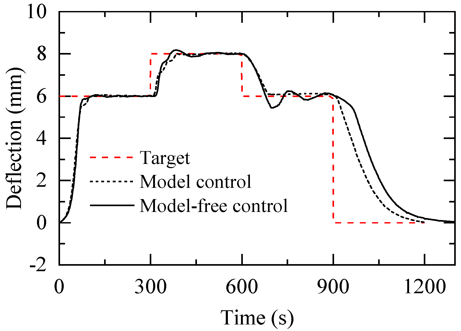
For model-free control, deflection is used as the feedback quantity of the control system, and temperature feedback related to the Preisach model of the SMA-based actuator is removed. With the other conditions being unchanged, the effect of the modeled control and the model-free control is compared in Figure 20. In Step 1, both the model control and model-free control present a better control effect. Compared to the model control, the model-free control shows a slightly longer steady-state time. In Step 2, compared to the modeled control, in addition to the long steady-state time, the model-free control shows a large amount of overshoot. In Step 3, the model-free control cannot reach the control target within 300 s. On the contrary, the model control presents a good control effect. As a result, the time-domain performance index of the modeled control and model-free control includes steady-state time, steady-state error, and relative error, which are summarized in Table 4.
In this table, we can see that the steady-state time of each control step is around 100s under the condition of the modeled control, which means that a fast response can be achieved through this control method in practical application. For the control of the relative error, this control method also has a good performance, through which the most significant relative error of the modeled control occurs in Step 3, at 5.45%.
5. Conclusions
In this work, an SMA-based actuator, including an entire procedure for designing and controlling it, is proposed. An improved thermomechanical cycling treatment is used to provide a more reliable two-way memory effect (TWSME) for SMAs. By increasing the temperature of the SMA strips, a maximum deflection of about 10 mm can be provided at the upper edge of the SMA-based actuator.
Considering the non-linearity of temperature and deformation that the SMAs exhibit while being tested, a hysteresis model is established based on Preisach for the SMAs, and the F function method (FFM) is used for the numerical realization of the Preisach model. In addition, an experimental data collection method is used to build a framework for the Preisach plane. The interpolated Preisach plane is able to obtain the correspondence between the target deflection and target temperature of SMAs, which can be used to predict the deflection changes more efficiently and accurately.
During the experiment steps, according to the target deflection of the SMA-based actuator, the Preisach plane is divided to obtain the heating temperature range, which is combined with PID control, and a PID-based Preisach model controller is established to control the deflection of the SMA-based actuator. Additionally, the calculation module of MATLAB is invoked by LabVIEW to achieve the programming. The maximum relative error at the three target points in the experiment on model controller is 5.45%, and the effect of model control is better than that of model-free control. The accuracy achieved by the modeled control makes it possible to use SMA-based actuators effectively for many applications.
Author Contributions
Conceptualization, R.L., C.Z. (Chen Zhang), H.J., C.Z. (Chao Zhang) and J.Q.; Methodology, R.L. and C.Z. (Chen Zhang); Software, R.L.; Formal analysis, R.L.; Data curation, R.L. and C.Z. (Chen Zhang); Writing—original draft, R.L.; Writing—review & editing, C.Z. (Chen Zhang) and H.J.; Supervision, H.J. and J.Q.; Funding acquisition, H.J. All authors have read and agreed to the published version of the manuscript.
Funding
This research was funded by National Key Research and Development Program of China (No. 2021YFB3400100), National Natural Science Foundation of China (No. 52022039), State Key Laboratory of Mechanics and Control of Mechanical Structures (Nanjing University of Aeronautics and astronautics) (No. MCMS-I-0521G03).
Institutional Review Board Statement
Not applicable.
Informed Consent Statement
Not applicable.
Data Availability Statement
Not applicable.
Conflicts of Interest
The authors declare no conflict of interest.
Glossary
| u(t) | Signal input |
| y(t) | Preisach model output |
| Preisach density function | |
| Hysteresis operator | |
| Hysteresis operator corresponds to ‘up’ switching values of input | |
| Hysteresis operator corresponds to ‘down’ switching values of input | |
| Peaks of the previous input signal | |
| Valleys of the previous input signal | |
| e(t) | Error signal |
| yd(t) | Setpoint signal |
| y(t) | Process variable |
| u(t) | Control signal |
| e(n) | Error at time instant (n) |
| u(n) | Control output at time instant (n) |
| kp | Proportional gain |
| ki | Integral gain |
| kd | Derivative gain |
References
- Barbarino, S.; Bilgen, O.; Ajaj, R.M.; Friswell, M.I.; Inman, D.J. A Review of Morphing Aircraft. J. Intell. Mater. Syst. Struct. 2011, 22, 823–877. [Google Scholar] [CrossRef]
- Liu, B.; Liang, H.; Han, Z.-H.; Yang, G. Surrogate-based aerodynamic shape optimization of a morphing wing considering a wide Mach-number range. Aerosp. Sci. Technol. 2022, 124, 107557. [Google Scholar] [CrossRef]
- McGowan, A.-M.R.; Pitt, D.M.; Dunne, J.P.; White, E.V. SAMPSON smart inlet design overview and wind tunnel test: I. Design overview. In Proceedings of the Smart Structures and Materials 2002: Industrial and Commercial Applications of Smart Structures Technologies, San Diego, CA, USA; 2002; pp. 13–23. [Google Scholar]
- Zhang, C.; Liu, R.; Tao, C.; Zhang, C.; Ji, H.; Qiu, J. Design, construction, and modeling of aircraft door sealing plate based on SMAs. Int. J. Smart Nano Mater. 2022, 13, 481–503. [Google Scholar] [CrossRef]
- Andonovski, B.; Wang, J. Computer Vision System for Cabin Door Detection and Location. In Proceedings of the 2018 15th International Conference on Control, Automation, Robotics and Vision (ICARCV), Singapore, 18–21 November 2018; pp. 1537–1542. [Google Scholar]
- Hu, K.; Rabenorosoa, K.; Ouisse, M. A Review of SMA-Based Actuators for Bidirectional Rotational Motion: Application to Origami Robots. Front. Robot. AI 2021, 8, 678486. [Google Scholar] [CrossRef]
- Monner, H.; Kintscher, M.; Lorkowski, T.; Storm, S. Design of a Smart Droop Nose as Leading Edge High Lift System for Transportation Aircrafts. In Proceedings of the 50th AIAA/ASME/ASCE/AHS/ASC Structures, Structural Dynamics, and Materials Conference, Palm Springs, CA, USA, 4–7 May 2009. [Google Scholar]
- Jinks, E.R.; Bruce, P.J.; Santer, M.J. Adaptive Shock Control Bumps. In Proceedings of the 52nd Aerospace Sciences Meeting, National Harbor, MD, USA, 13–17 January 2014. [Google Scholar]
- Bahl, S.; Nagar, H.; Singh, I.; Sehgal, S. Smart materials types, properties and applications: A review. Mater. Today Proc. 2020, 28, 1302–1306. [Google Scholar] [CrossRef]
- Kumar, P.K.; Lagoudas, D.C. Introduction to Shape Memory Alloys. In Shape Memory Alloys: Modeling and Engineering Applications; Springer Science+Business Media Deutschland GmbH: Berlin, Germany, 2008; pp. 1–51. Available online: http://www.springer.com (accessed on 15 November 2022). [CrossRef]
- Otsuka, K.; Wayman, C. Shape Memory Materials; Cambridge University Press: Cambridge, UK, 1998; p. 284. [Google Scholar]
- Bhaskar, J.; Sharma, A.K.; Bhattacharya, B.; Adhikari, S. A review on shape memory alloy reinforced polymer composite materials and structures. Smart Mater. Struct. 2020, 29, 073001. [Google Scholar] [CrossRef]
- Mohd Jani, J.; Leary, M.; Subic, A.; Gibson, M.A. A review of shape memory alloy research, applications and opportunities. Mater. Des. 2014, 56, 1078–1113. [Google Scholar] [CrossRef]
- Barbarino, S.; Saavedra Flores, E.I.; Ajaj, R.M.; Dayyani, I.; Friswell, M.I. A review on shape memory alloys with applications to morphing aircraft. Smart Mater. Struct. 2014, 23, 063001. [Google Scholar] [CrossRef]
- Stroud, H.; Hartl, D. Shape memory alloy torsional actuators: A review of applications, experimental investigations, modeling, and design. Smart Mater. Struct. 2020, 29, 113001. [Google Scholar] [CrossRef]
- Hao, L.; Qiu, J.; Ji, H.; Nie, R. Numerical analysis on shape memory alloy–based adaptive shock control bump. J. Intell. Mater. Syst. Struct. 2018, 29, 3055–3066. [Google Scholar] [CrossRef]
- Calkins, F.T.; Mabe, J.H. Shape Memory Alloy Based Morphing Aerostructures. J. Mech. Des. 2010, 132, 111012. [Google Scholar] [CrossRef]
- Dana, M.E.; Aarash Yusefzadeh Nagh, S.; Haydn, N.G.W. A bio-inspired high-authority actuator for shape morphing structures. In Smart Structures and Materials 2003: Active Materials: Behavior and Mechanics; SPIE: Bellingham, WA, USA, 2003; pp. 92–100. [Google Scholar]
- Wang, Z.; Yang, X.; Li, B. SMA-actuated Morphing Wing with Varying Spanwise Curvature and SweptAngle. In Proceedings of the 2019 IEEE International Conference on Robotics and Biomimetics (ROBIO), Dali, China, 6–8 December 2019; pp. 1615–1620. [Google Scholar] [CrossRef]
- Auricchio, F.; Boatti, E.; Conti, M.; Marconi, S. Chapter 19—SMA biomedical applications. In Shape Memory Alloy Engineering, 2nd ed.; Concilio, A., Antonucci, V., Auricchio, F., Lecce, L., Sacco, E., Eds.; Butterworth-Heinemann: Boston, MA, USA, 2021; pp. 627–658. [Google Scholar] [CrossRef]
- Luji, F.F.J.; Teo, K.T.; Tan, S.; Yoong, H. Heating and Cooling Mechanisms for SMA Actuator-A Brief Review. Trans. Sci. Technol. 2021, 8, 425–431. [Google Scholar]
- Zhang, C.; Ji, H.; Chen, X.; Qiu, J. Thermomechanical training and structural tests for adaptive SMA bumps with two-way shape memory effect. J. Intell. Mater. Syst. Struct. 2021, 33, 1308–1320. [Google Scholar] [CrossRef]
- Jayender, J.; Patel, R.V.; Nikumb, S.; Ostojic, M. Modeling and Control of Shape Memory Alloy Actuators. IEEE Trans. Control Syst. Technol. 2008, 16, 279–287. [Google Scholar] [CrossRef]
- Ahn, K.K.; Kha, N.B. Modeling and control of shape memory alloy actuators using Preisach model, genetic algorithm and fuzzy logic. Mechatronics 2008, 18, 141–152. [Google Scholar] [CrossRef]
- Mitrev, R.; Todorov, T.; Fursov, A.; Ganev, B. Theoretical and Experimental Study of a Thermo-Mechanical Model of a Shape Memory Alloy Actuator Considering Minor Hystereses. Crystals 2021, 11, 1120. [Google Scholar] [CrossRef]
- Webb, G.V.; Lagoudas, D.C.; Kurdila, A.J. Hysteresis modeling of SMA actuators for control applications. J. Intell. Mater. Syst. Struct. 1998, 9, 432–448. [Google Scholar] [CrossRef]
- Ikhouane, F. A Survey of the Hysteretic Duhem Model. Arch. Comput. Methods Eng. 2018, 25, 965–1002. [Google Scholar] [CrossRef]
- Chun-Yi, S.; Qingqing, W.; Xinkai, C.; Rakheja, S. Adaptive variable structure control of a class of nonlinear systems with unknown Prandtl-Ishlinskii hysteresis. IEEE Trans. Autom. Control 2005, 50, 2069–2074. [Google Scholar] [CrossRef]
- Wang, Z.G.; Zu, X.T.; Feng, X.D.; Lin, L.B.; Zhu, S.; You, L.P.; Wang, L.M. Design of TiNi alloy two-way shape memory coil extension spring. Mater. Sci. Eng. A 2003, 345, 249–254. [Google Scholar] [CrossRef]
- Otsuka, K.; Ren, X. Recent developments in the research of shape memory alloys. Intermetallics 1999, 7, 511–528. [Google Scholar] [CrossRef]
- Luo, H.Y.; Abel, E.W. A comparison of methods for the training of NiTi two-way shape memory alloy. Smart Mater. Struct. 2007, 16, 2543–2549. [Google Scholar] [CrossRef]
- Yan, L.; Liu, Y. Wear Behavior of Austenitic NiTi Shape Memory Alloy. Shape Mem. Superelasticity 2015, 1, 58–68. [Google Scholar] [CrossRef] [Green Version]
- Preisach, F. ber die magnetische Nachwirkung. Z. Phys. 1935, 94, 277–302. [Google Scholar] [CrossRef]
- Tang, Z.-f.; Lv, F.-z.; Xiang, Z.-q. Hysteresis model of magnetostrictive actuators and its numerical realization. J. Zhejiang Univ.-Sci. A 2007, 8, 1059–1064. [Google Scholar] [CrossRef]
- Jung, J.-K.; Park, Y.-W. Hysteresis modeling and compensation in a magnetostrictive actuator. In Proceedings of the 2008 International Conference on Control, Automation and Systems, Seoul, Republic of Korea, 14–17 October 2008. [Google Scholar] [CrossRef]
- Crowe, J.; Tan, K.; Lee, T.; Ferdous, R.; Katebi, M.; Huang, H.-P.; Jeng, J.-C.; Tang, K.; Chen, G.; Man, K.; et al. PID Control: New Identification and Design Methods; Michael, A., Johnson, M.H.M., Eds.; Springer: London, UK, 2005; Volume XXVIII, p. 544. [Google Scholar] [CrossRef]
Figure 1.
DSC results of SMA samples.
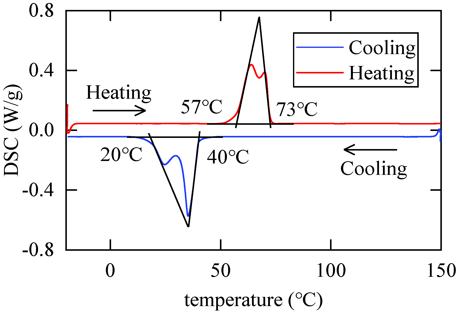
Figure 2.
Uniaxial loading results of the SMA strip.

Figure 3.
The training system for the SMA strip.
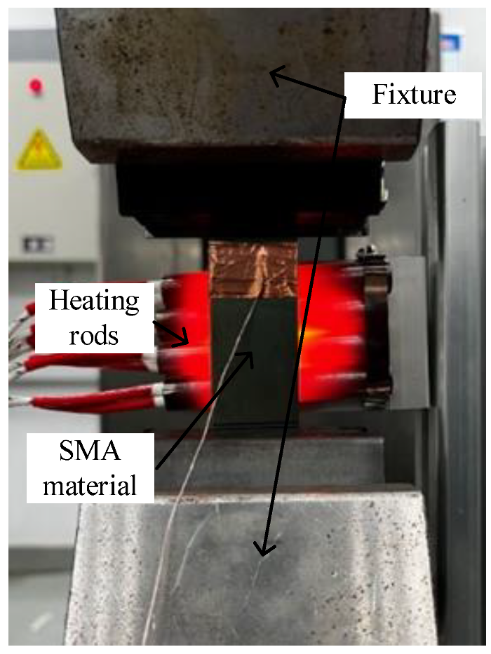
Figure 4.
Loading and temperature variation curves of SMA strip during the training process.
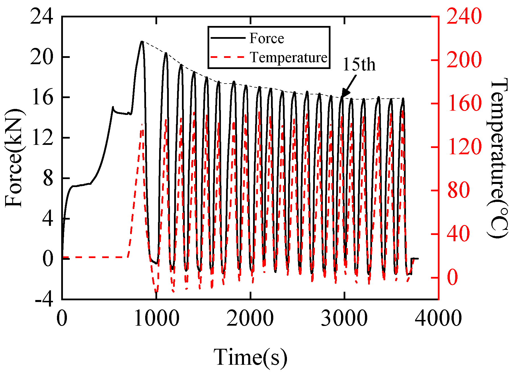
Figure 5.
Deflection testing setup for the SMA-based actuator.
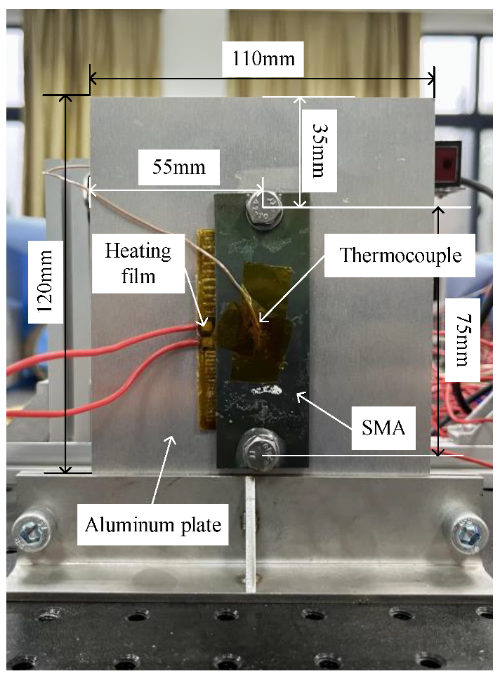
Figure 6.
Deflection results for the SMA-based actuator.

Figure 7.
SMA-based actuator schematic.
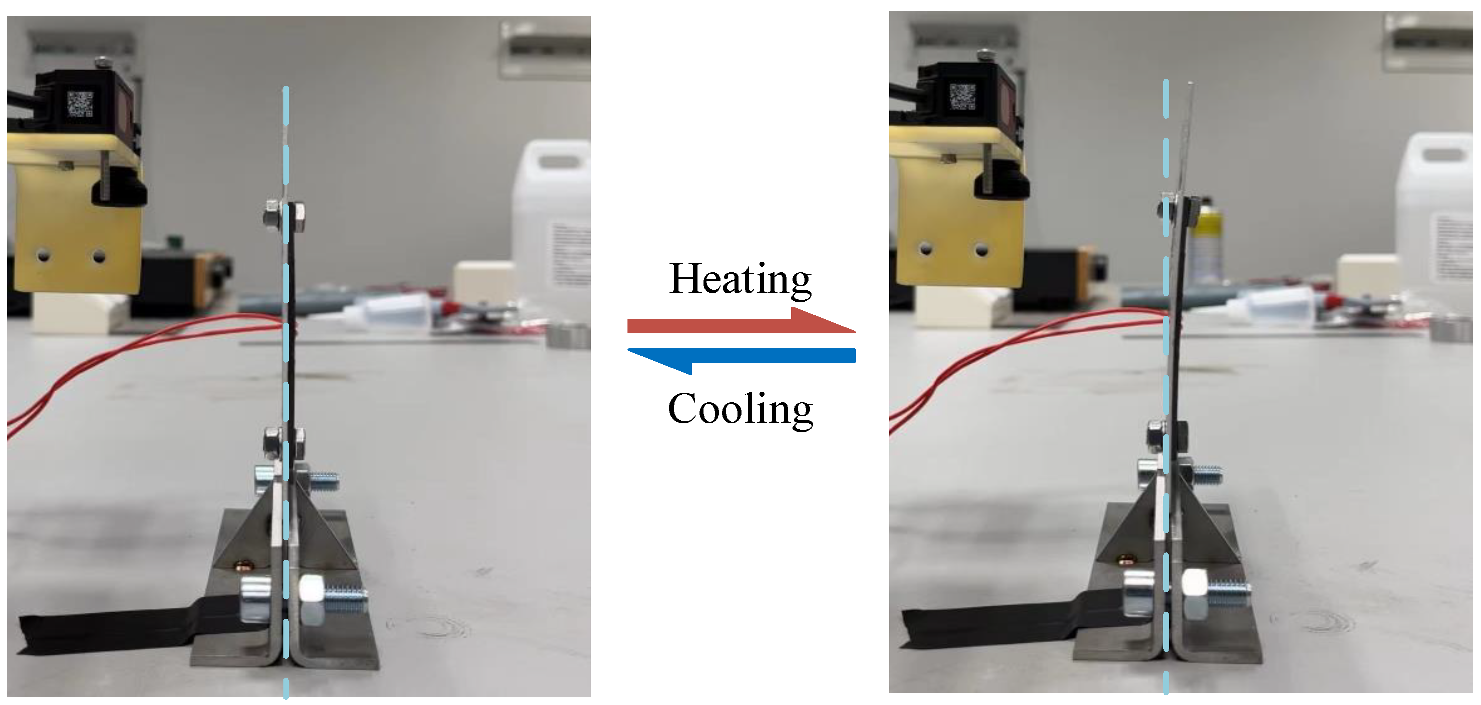
Figure 8.
Diagram of the Preisach model.

Figure 9.
Geometric interpretation of the Preisach model.
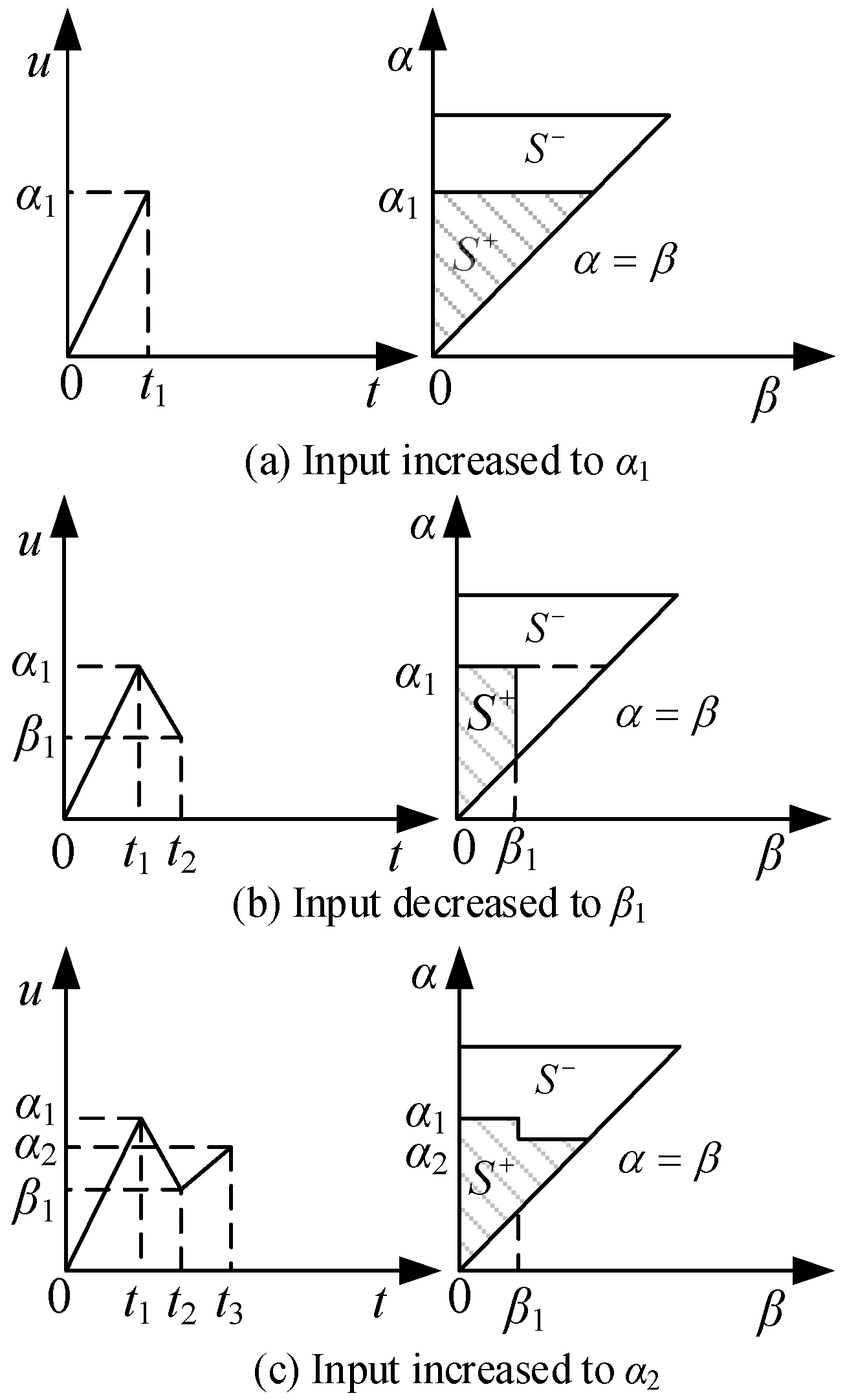
Figure 10.
First-order reversal descending curve.
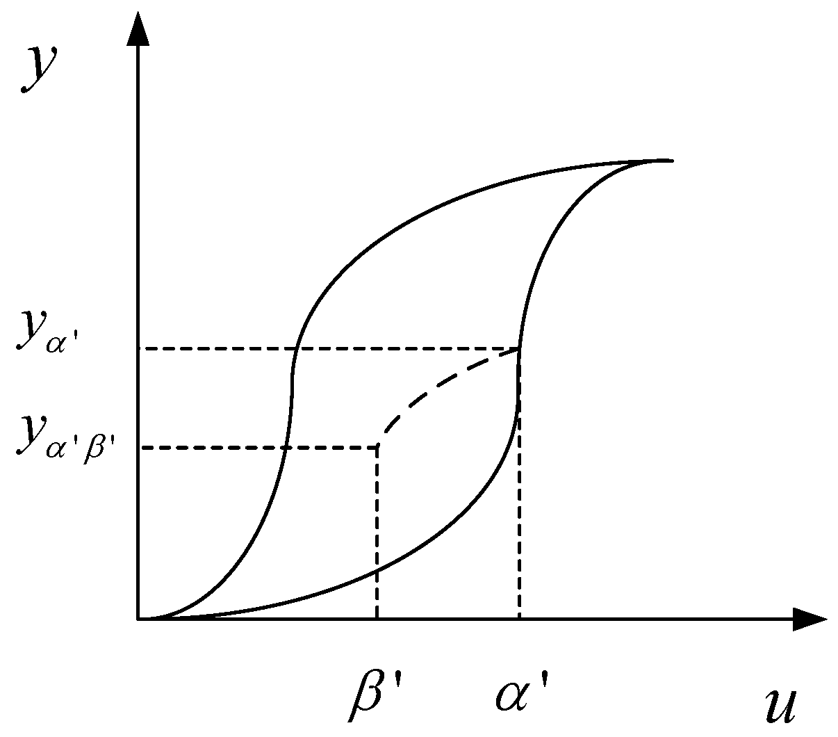
Figure 11.
Memory curve separates the Preisach plane.
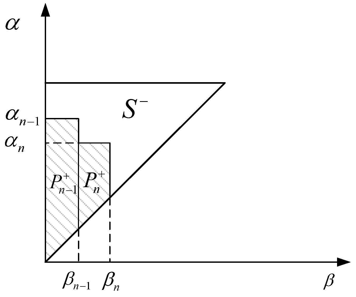
Figure 12.
The situations of the last variation of the input. (a) the latest variation of input is decreasing; (b) the latest variation of input is increasing.
Figure 12.
The situations of the last variation of the input. (a) the latest variation of input is decreasing; (b) the latest variation of input is increasing.

Figure 13.
Preisach plane.

Figure 14.
Principle of PID control.

Figure 15.
Experimental apparatus.
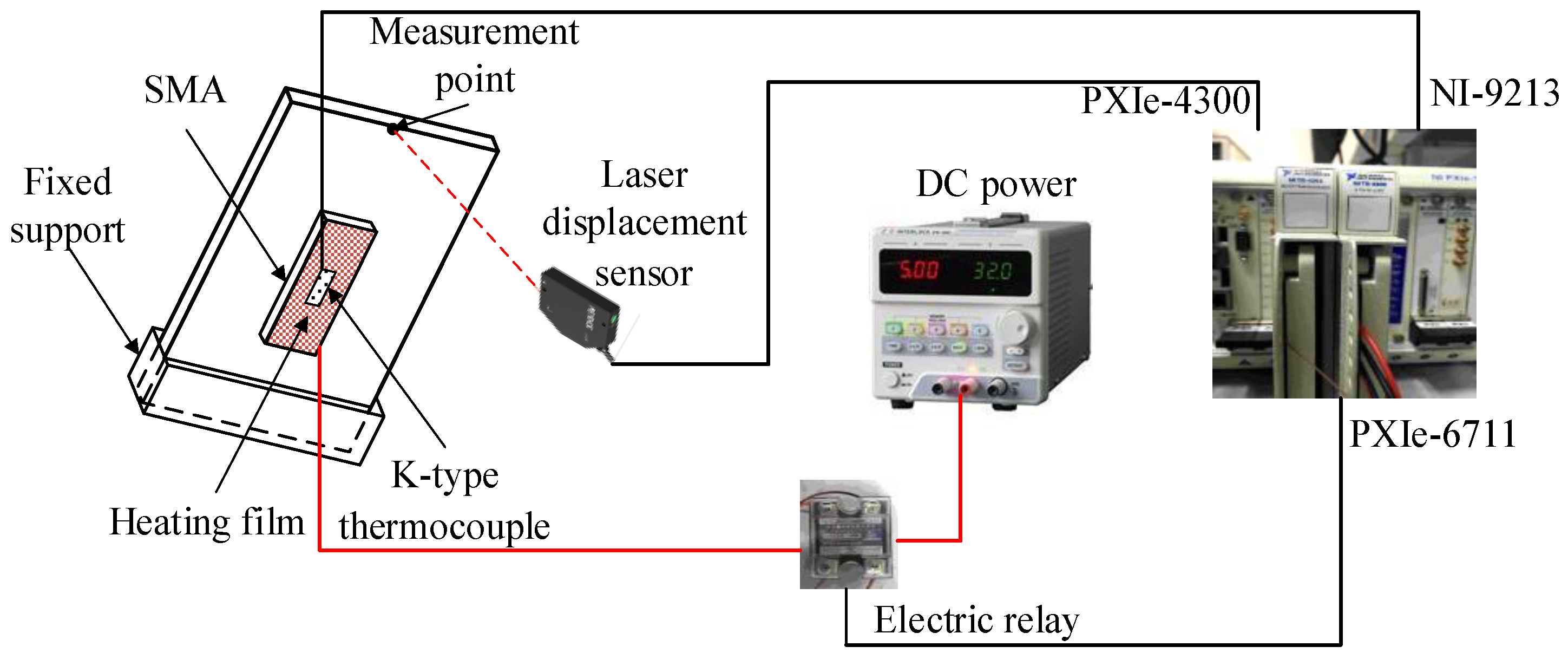
Figure 16.
Control program structure of LABVIEW.
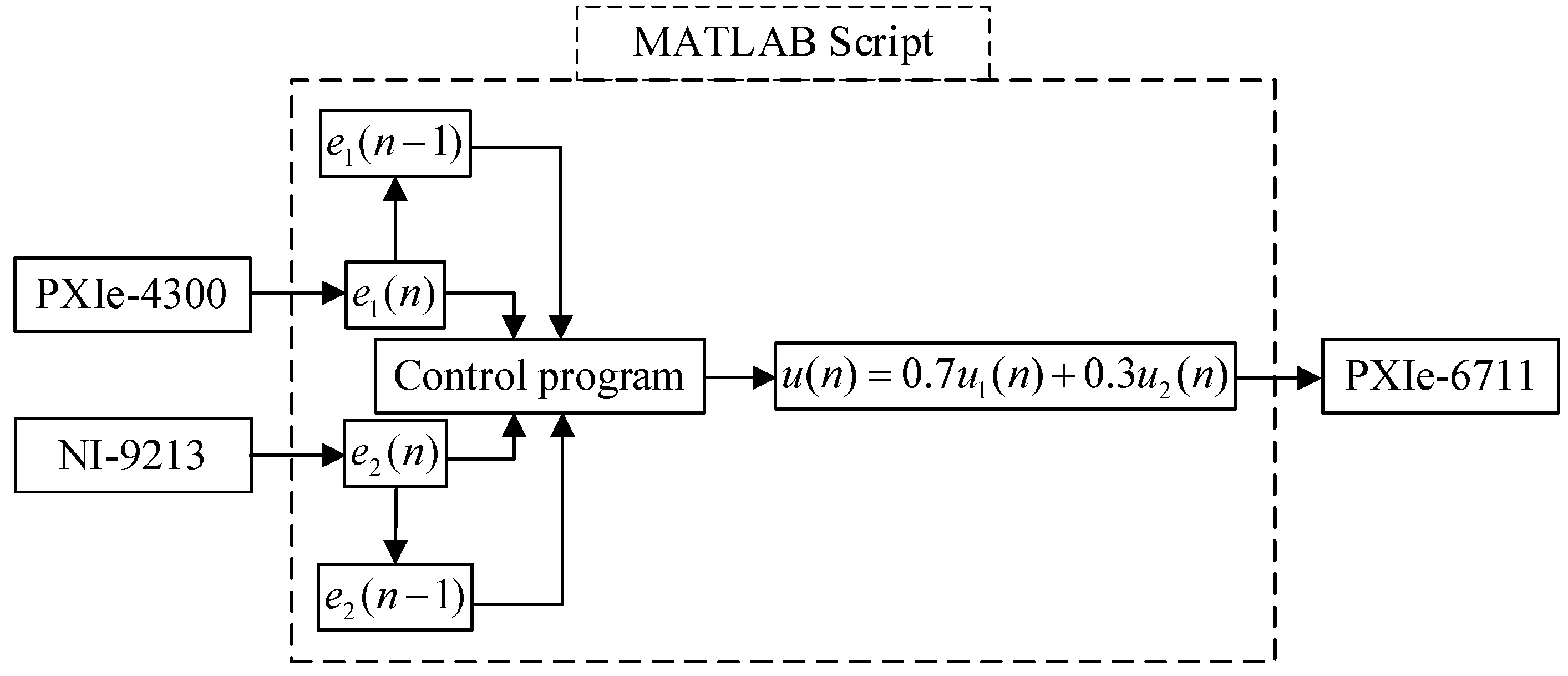
Figure 17.
Model control result and the target values.

Figure 18.
Temperature change over time.
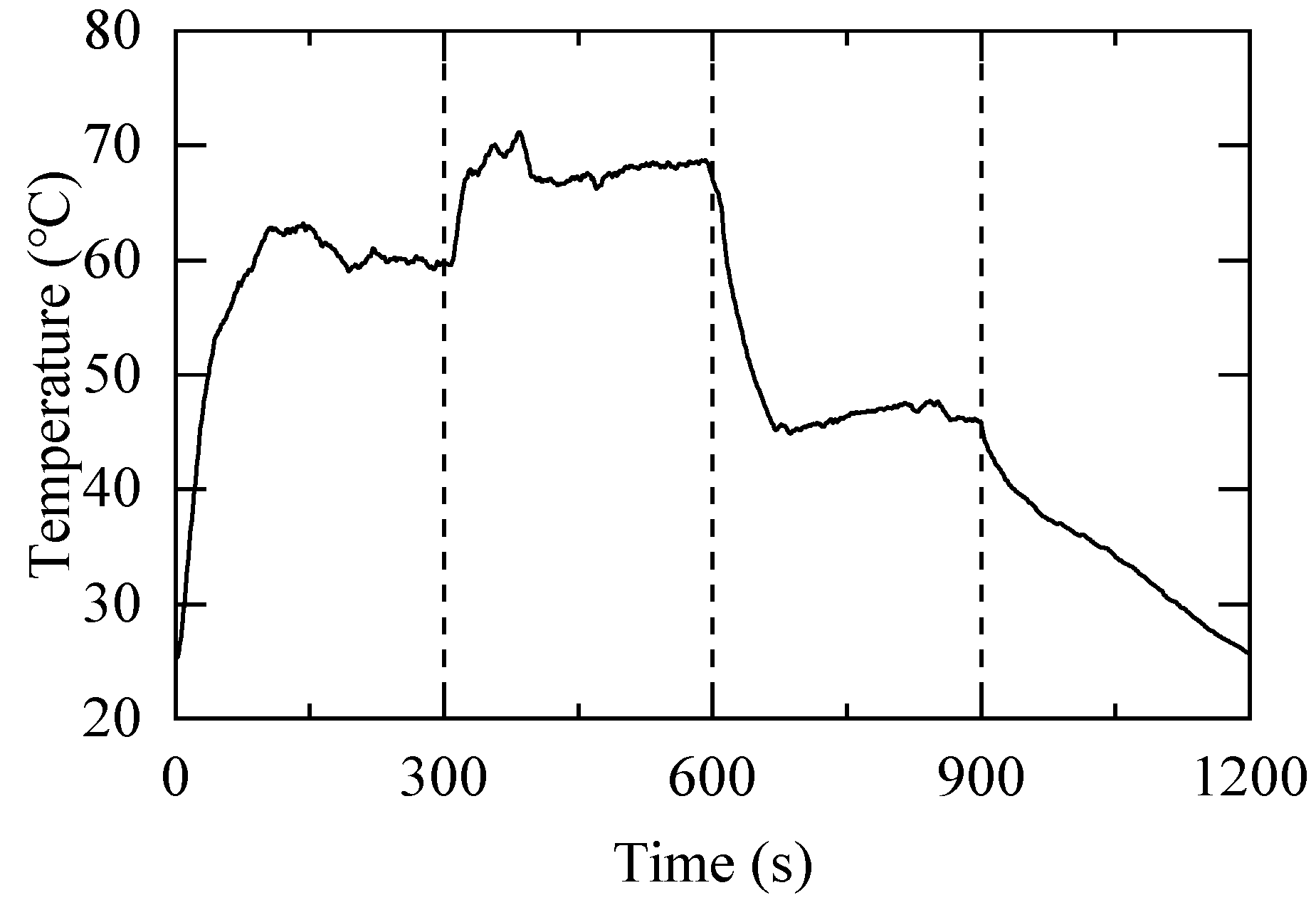
Figure 19.
Temperature–deflection result.

Figure 20.
Comparison of control with and without a model.

Table 1.
Material properties for SMA strips.
| Property | Value | Property | Value |
|---|---|---|---|
| Mf (℃) | 40 | EM (GPa) | 11.4 |
| Ms (℃) | 20 | EA (GPa) | 18 |
| Af (℃) | 73 | Poisson’s ratio | 0.33 |
| As (℃) | 57 | Density (g/cm3) | 6.5 |
Table 2.
TWSME thermomechanical cycling training method.
| Step | Training Procedure |
|---|---|
| 1 | Load the SMA strip in martensite state to 7% of its original length; |
| 2 | Heat it above Af and below Md in the constrained condition; |
| 3 | Cool it below Mf in the constrained condition; |
| 4 | Repeat Step 2 and Step 3 several times; |
Here, Md refers to the temperature above which SMA loses superelasticity [32].
Table 3.
Control targets.
| Step | Deflection (mm) | Temperature Range (°C) |
|---|---|---|
| 1 | 0–6 | 25–60 |
| 2 | 6–8 | 60–69 |
| 3 | 8–6 | 69–45.5 |
Table 4.
Time-domain performance index.
| Control Method | Step | Steady-State Time (s) | Steady-State Error (mm) | Relative Error (%) |
|---|---|---|---|---|
| Modeled control | 1 | 106 | 0.066 | 1.10% |
| 2 | 97 | 0.045 | 2.25% | |
| 3 | 87 | 0.109 | 5.45% | |
| Model-free control | 1 | 138 | 0.051 | 0.85% |
| 2 | 183 | 0.053 | 2.65% | |
| 3 |
Disclaimer/Publisher’s Note: The statements, opinions and data contained in all publications are solely those of the individual author(s) and contributor(s) and not of MDPI and/or the editor(s). MDPI and/or the editor(s) disclaim responsibility for any injury to people or property resulting from any ideas, methods, instructions or products referred to in the content. |
© 2023 by the authors. Licensee MDPI, Basel, Switzerland. This article is an open access article distributed under the terms and conditions of the Creative Commons Attribution (CC BY) license (https://creativecommons.org/licenses/by/4.0/).
Share and Cite
MDPI and ACS Style
Liu, R.; Zhang, C.; Ji, H.; Zhang, C.; Qiu, J. Training, Control and Application of SMA-Based Actuators with Two-Way Shape Memory Effect. Actuators 2023, 12, 25. https://doi.org/10.3390/act12010025
AMA Style
Liu R, Zhang C, Ji H, Zhang C, Qiu J. Training, Control and Application of SMA-Based Actuators with Two-Way Shape Memory Effect. Actuators. 2023; 12(1):25. https://doi.org/10.3390/act12010025
Chicago/Turabian StyleLiu, Renhao, Chen Zhang, Hongli Ji, Chao Zhang, and Jinhao Qiu. 2023. "Training, Control and Application of SMA-Based Actuators with Two-Way Shape Memory Effect" Actuators 12, no. 1: 25. https://doi.org/10.3390/act12010025
Note that from the first issue of 2016, this journal uses article numbers instead of page numbers. See further details here.