
Effect of Mn Doping on the Microstructure and Electrical Properties of Potassium Niobate Ceramics Using Plasma Spraying
1
School of Mechanical Engineering, Xi’an University of Science and Technology, Xi’an 710048, China
2
National Key Lab for Remanufacturing, Army Armored Forces Institute, Beijing 100072, China
*
Authors to whom correspondence should be addressed.
Actuators 2022, 11(12), 343; https://doi.org/10.3390/act11120343
Submission received: 28 September 2022
/
Revised: 14 November 2022
/
Accepted: 17 November 2022
/
Published: 23 November 2022
(This article belongs to the Special Issue Shape Memory Alloys and Piezoelectric Materials and Their Applications)
Abstract
:KNN piezoelectric ceramics are of great importance in the field of scientific research due to their high Curie temperature, good electrical properties, etc. The application of potassium sodium niobate K0.5Na0.5NbO3 (KNN) is strictly limited due to the volatility of Na+ and K+ in KNN and its leakage current. In order to investigate the effect of Mn doping on KNN-based piezoelectric ceramic coatings, KNN and KNN-0.02Mn (KNMN) coatings were successfully prepared using a plasma spraying technique. The phase structure, microscopic morphology, and electrical properties of the coatings were studied in the research. The results showed that both the KNN and KNMN coatings had chalcogenide structures. The KNN coating had an orthogonal phase structure, whereas the KNMN coating had a tetragonal phase structure. Compared with the KNN coating, the microhardness of the KNMN coating was improved through doping with Mn ions. The doping of Mn ions could replace both the A and B sites in the KNN piezoelectric ceramics, further reducing the oxygen vacancies and leakage currents in the coating, and its dielectric properties were improved.
1. Introduction
Piezoelectric materials are important functional materials for the conversion of mechanical and electrical energy, and have a wide range of applications in various electronic components, such as sensors, actuators, ultrasonic transducers, resonators, filters, buzzers, and electronic igniters. Meanwhile, piezoelectric ceramics play an important role in scientific research due to their efficient piezoelectric effect as well as their low price and good electrical properties [1,2,3,4]. Currently, widely used piezoelectric ceramic materials are mainly comprised of lead zirconate titanate (PZT). The advantages of these piezoelectric ceramics are their excellent electrical properties and the possibility of industrial mass production. However, the Pb ions contained in the ceramics can cause a lot of harm to the environment. Thus, lead-free piezoelectric ceramics have been widely studied to replace lead-based piezoelectric ceramics [5,6]. Potassium sodium niobate (KNN) piezoelectric ceramics are currently considered as a viable alternative to PZT. Although the performance of pure KNN is inferior to that of PZT, its relatively high Curie temperature, good electrical properties, and high electromechanical coupling coefficient are the driving forces for KNN research [7,8,9].
However, there are still some practical problems that hinder the industrial application of KNN. The volatilization of KNN components is considered to be the reason for the low density and high defect concentration of KNN ceramics, which adversely affect their conductivity and ferroelectric performance behavior [10,11]. At the same time, leakage current plays an important role in polarization switching, as well as polarization processes, making it difficult for materials to obtain optimal piezoelectric properties and rendering them unsuitable for industrial applications [12]. Mn ions are often used as dopants in Pb-based materials for mechanical quality factor enhancement and dielectric loss reduction [13,14]. Huang et al. [15] used a solid-state reaction method to prepare Mn-ion-doped Pb(Mg0.5W0.5)O3-Pb(Zr, Ti)O3(PMW-PZT) ceramics. The study showed that the electrical properties of the ceramics were effectively improved. Peng et al. [16] adopted the sol–gel method to prepare Mn-ion-doped PZT piezoelectric ceramic films. The results showed that 1 mol% Mn could achieve sender doping, which was beneficial to the domain movement and further enhanced the ferroelectric properties of the PZT films. In addition, Mn plays an important role in lead-free piezoelectric ceramics, such as BaTiO3 and KNbO3, by enhancing the densities, dielectric losses, and electrical properties of ceramics [17,18]. Current research on KNN-based piezoelectric ceramics focuses on bulk ceramics, single crystals, and thin films. Mn can reduce the leakage current density of potassium sodium niobate, which has little effect on the dielectric properties of doped KNN ceramics [19]. Wang et al. [20] used chemical solution deposition to prepare KNN thin films with different Mn doping contents. The results showed that the doping of Mn ions reduced the KNN leakage current density and the electrical properties were effectively improved, which, in turn, enhanced the ferroelectric properties of the films [21]. Shweta et al. [22] prepared KxNa1-xNbO3 thin films with a pulsed laser deposition technique. The effect of the deposition parameters on the structure and morphology of KNN thin films was investigated. The results showed that the KNN films had a dielectric constant of approximately531 in the high-frequency region (>500 kHz) and a residual polarization of 8.63 µC cm−2. Although a solid-phase sintering method, hot-pressure sintering method, and laser pulse deposition technology have been applied in current KNN-based piezoelectric ceramics preparation techniques, and extensive research on Mn in KNN-based systems has been conducted, the effect of Mn on the properties of KNN-based piezoelectric ceramics prepared using a thermal spray technique is still unclear.
Plasma spraying is a thermal spraying method in which a piezoelectric ceramic powder is fed into a plasma jet, heated and accelerated in it, and sprayed onto different substrates to form coatings [23,24]. Due to its characteristics of a high-ion flame flow temperature, fast spraying particle velocity, and controllable thickness, plasma spraying can ensure the density of the coating and reduce its porosity under the premise of the full melting of the sprayed powder, thus, achieving a wider application prospect [25,26]. Chen et al. [27] prepared KNN-based piezoelectric ceramic coatings with a single chalcogenide phase and a dense morphology with a thermal spraying process. The structure, morphology, and properties of the coatings deposited under different conditions were investigated, and their excellent piezoelectric properties were demonstrated. Chen et al. [28] obtained a large effective piezoelectric coefficient (d33) of 125 μm/V by thermal spraying KNN-based ceramic coatings onto steel substrates with a thermal spray process for the first time after the introduction of a nickel- and yttria-stabilized zirconia interlayer. Zhou et al. [29] prepared KNN-based piezoelectric ceramic coatings using supersonic plasma spraying equipment. The research results showed that the coatings had a good quality, as well as good electrical properties. Song et al. [30] prepared Li-ion-doped KNLN-based piezoelectric ceramic coatings using supersonic plasma spraying technology. The coatings had good electrical properties, with a dielectric constant of 375 and a stable dielectric loss of 0.01, and Li ion doping could successfully build a polycrystalline phase interface with the coexistence of an O–T phase boundary. Therefore, the plasma spraying technique provides a new prospect for the preparation of KNN-based piezoelectric ceramics.
The current research on the preparation of KNN-based piezoelectric ceramics using thermal spraying technology is relatively rare. In this paper, MnCO3-doped KNN piezoelectric ceramics were prepared by using plasma spraying technology. The effects of Mn ion doping on the microstructure, mechanical properties, and electrical properties of KNN piezoelectric ceramics were investigated to reveal the mechanism of the effect for Mn ion doping on coating properties. In addition, the effect of oxygen vacancies on the ferroelectric properties was discussed in detail.
2. Experimental Procedure
2.1. KNN Powder and Coating Preparation
K0.50Na0.50NbO3 (KNN) and K0.50Na0.50NbO3-0.02Mn (KNMN) powders were adopted as raw materials (Quanzhou Qijin New Material Technology Limited Company, Quanzhou, China). Based on previous research on KNN piezoelectric ceramics, 10 mol% more K and Na was added considering the volatilization of alkaline metal ions during the thermal spraying process. The plasma spraying equipment had the advantages of a fast spraying speed and high spraying temperature, and its schematic diagram is shown in Figure 1.
Since plasma spraying technology is suitable for the preparation of ceramic coatings due to the high temperature and speed of the jet flame center, which can melt many refractory materials, the spraying process requires a certain size and fluidity of powder, and this, in turn, affects the quality of the ceramic coating. A powder particle size that is too small can form an agglomeration in the process of powder charging or be directly melted in the process of spraying due to the high temperature of the jet flame center. As a result, the particles cannot be deposited in the substrate. Therefore, the powder had to be atomized using granulation, sieving, etc., so that the appropriate KNN and KNMN powder particle sizes could be achieved, as shown in Figure 2. It can be seen that the particle sizes of the two powders were mainly concentrated at approximately 30–80μm, where d(0.1) = 0.722, d(0.5) = 40.059, and d(0.9) = 77.972; the preparation of the powder was fully suitable for the plasma spraying system.
The sprayed substrate was selected from the 45th steel with a processing size of 25 mm × 20 mm × 5 mm. Before spraying, the surface of the substrate specimen was ultrasonically cleaned with acetone and ethanol to remove oil contamination, and then sandblasted with aluminum oxide to remove oxides and other impurities to increase the roughness of the substrate surface. Next, Ni-based alloy compounds were sprayed onto the substrate surface to increase the bond strength between the substrate and the coating. Prior to spraying, the substrate surface was prepped by plasma spraying it for preheating to a temperature of 90–110 °C with the preheating time set to 15 s. Plasma spraying equipment was applied in the research and the spraying process parameters are listed in Table 1, displaying a spraying thickness of 250 μm. To enhance the electrical properties of the coating, it was heated at 600 °C in a KSL-1100X-S chamber furnace for approximately 30 min.
2.2. Powder and Coating Performance Testing
The particle size of the powders was analyzed with a laser particle sizer (Mastersizer 2000 model); the 3D morphology of the coatings was obtained with a 3D morphological profiler (Nanovea ST400, Nanovea, Irvine, CA, USA) at a magnification of 200 times; the morphology of the powder, as well as the cross-sectional morphology of the coating, was obtained using a field emission scanning electron microscope (SEM; ZEISS Gemini, Oberkochen, Germany). Chemical elements were analyzed using energy-dispersive spectroscopy (EDS, ZEISS Gemini, Oberkochen, Germany); the phase structure of the powders and coatings was analyzed with an X-ray diffractometer (D/MAX-RB; Tokyo, Japan) at a wavelength of λ = 0.15406 nm, a Cu target, a scanning speed of 4°/min, and a scanning angle of 20°–60°. The microhardness of the two coatings was tested using a microhardness tester (KELITI000ZB, Sichuan, China). The bond strength of the coatings was tested using an MTS fatigue tester. Upper and lower electrodes were prepared to test the electrical properties of the KNN and KNMN coatings. Bottom electrodes 3 mm in diameter were prepared using an ion sputtering method. The specimens were polarized using high-temperature polarization equipment (KSL-1100X, Hefei, China). The dielectric constant and dielectric loss were tested at room temperature using an impedance analyzer (Agilent 4294A, NANOVEA, Irvine, CA, USA) at a frequency of 1 kHz. In addition, the ferroelectric properties of the coatings were tested using a ferroelectric analyzer (TF Analyzer 2000E, Beijing, China). An X-ray electron spectrometer (XPS; Thermo escalab 250XI, USA) was used to analyze the elemental valence states of the coatings. In addition, the following applied: excitation source: Al Kα (hv = 1486.6 eV); electron emission angle: 55°; test area: 650 μm × 650 μm; Ar+ energy: 2000 eV; angle: 50°; analysis pressure: 10−10 mba. To reduce the error, we referred to the Fermi edge (EfB) of the critical carbon used in Liviu’s work [31] for the calibration. The relationship between the work function of the sample (ΦSA) and the Fermi edge (EfB) was EfB = 289.58 eV-ΦSA. Since the work function of the piezoelectric ceramic was ΦSA = 4.8 eV [31], EfB = 284.78 eV was used as the reference value for the BE.
3. Results and Discussion
3.1. Organizational Structure and Phase Structure
The roughness of the coating surface was one of the factors influencing the appearance of the coating, as well as its performance in use. Figure 3 represents the three-dimensional morphology of the KNN and KNMN coatings. As shown in Figure 3, the surface of the sprayed substrate specimen was uneven and had a certain degree of roughness. In the whole spraying process, the isoelectronic arc heat between the KNN powder and the KNMN powder was exchanged through the spray gun, thus, turning the powder into a molten or semimolten state. In the plasma spraying, the powder’s movement was accelerated in the flame. The KNN and KNMN powders could be melted due to the ultra-high temperature of the flame, so that the spraying process could be completed in a short period of time. The three-dimensional shape of the coating and the flatness of the surface were closely related to the molten powder’s distribution on the substrate surface.
As can be seen from Figure 3, the KNMN coating had a better spraying effect and a flatter coating surface. The difference between the highest point and the lowest point of the vertical height was only 29 μm, which was because the Mn ions were a sintering aid that could melt the KNN powder at a high temperature, and, then, could better accumulate it onto the surface of the substrate.
Figure 4a shows the cross-sectional morphology of the KNMN and KNN coatings. It is clearly visible that the thickness of both coatings was approximately 220 μm. No significant cracks existed between the two coatings and the substrate due to the introduction of the transition layer, which was an improvement in terms of the process. The porosity of the coatings was measured using image-pro software. The porosity of the KNN and KNMN coatings was obtained as 5.8% and 5.2%, respectively. With better quality and lower porosity, the KNMN coatings promoted the melting of the powder due to the doping of Mn, which was consistent with the results of the tests of the 3D morphology. Figure 4c represents the EDS of the KNMN-coated sample, from which it can be seen that the main elements were K, Na, Nb, O, and Mn. The distribution of the elements was relatively uniform and corresponded exactly to the coating structure of the sample. Table 2 indicates the content of elements in the KNMN coating, which showed that the elements in the coating and the powder remained consistent. The Mn ions went into the KNN coating. The volatilization of the elements came from the high temperature during the plasma spraying process, and C from the impurities brought on by the spraying process.
Figure 5 and Figure 6 represent the TEM/EDX surface scan element distribution and X-ray energy spectrum analysis of the KNMN coating, and the insets indicate the atomic percentages of each element of the KNMN coating; it can be seen from Figure 5 that the distribution of the K, Na, Nb, O, and Mn elements was relatively uniform. The figures showed that the distribution area of the Nb and O elements was relatively large, which was consistent with the properties of the original powder, where the content of the K and Na elements was low because of the high level of volatilization of alkaline metal ions caused by high temperatures during the plasma spraying process.
Figure 7a represents the XRD patterns of the KNN and KNMN powders. It was concluded that the KNN and KNMN powders both had a single chalcogenide structure. The Mn ions completely entered the KNN lattice because no formation of the second phase was observed in the XRD patterns [32]. Figure 7b represents the extended XRD patterns of the KNN and KNMN powders in the range of 2θ from 44° to 47°. Both powders had an orthoclase structure as the front peak was higher than the back peak at approximately45°.
Figure 8a represents the XRD patterns of the KNN and KNMN coatings. Both coatings showed a single chalcogenide structure. The KNMN coating exhibited a preferential orientation of 100. Figure 8b represents the extended XRD patterns of the KNN and KNMN coatings in the 2θ range of 44°–47°. It could be concluded that the KNN coating showed an orthogonal phase structure, while the KNMN coating displayed a tetragonal phase structure. Although the orthorhombic structure was the dominant phase at room temperature, with the doping of the Mn ions it changed to a structure dominated by a tetragonal phase structure. At the same time, the tetragonal orthogonal phase transition (TO-T) shifted to a lower temperature. The single chalcogenide phase also indicated that Mn could enter the KNN lattice by replacing the A site. It can be seen that the splitting phenomenon disappeared in the ceramics and that the diffraction peaks shifted toward smaller angles after the addition of a quantitative amount of Mn ions. Mn could replace both the A and B sites in KNN, thus, causing a distortion of the lattice structure and defects in the oxygen ions. In addition, the peak intensity of the KNMN coating was lower than that of the KNN coating, but the doping of the Mn ions enabled the KNMN coating to maintain a better crystal structure.
3.2. Mechanical Properties
The microhardness of the KNN and KNMN coatings is shown in Figure 9. From Figure 9a, it can be seen that the microhardness of the coatings tended to increase and then decrease from the coating to the substrate direction. The highest microhardness was in the transition layer, which was due to the fact that the material of the transition layer was NiCrCoAlY, so the microhardness of the coating was greater. The microhardness of the coating reflects the quality of the coating. As shown in Figure 9b, the microhardness of the KNMN coating was greater than that of the KNN coating because the doping of manganese ions during the spraying process promoted the melting of the ceramic powder, which increased the coating density and, thus, increased the microhardness, indicating that the KNMN coating was of better quality.
Figure 10 shows the bond strength of the KNN and KNMN coatings. The average values of the KNN and KNMN coating strengths were 23.8 MPa and 29.8 MPa, respectively, which could basically meet the requirements of actual working conditions. In terms of the fracture site of the specimens, the fracture locations were both located between the coating and the substrate, which further indicated that the coating was relatively dense, with better mechanical properties, and also proved that the bonding between the coating and the substrate was mainly based on mechanical bonding. The bonding strength of KNMN was better because of the introduction of Mn ions in the KNN coating, which promoted the melting of the powder during the spraying process and increased the coating density, thus, increasing the bonding strength of the coating.
3.3. Electrical Properties
3.3.1. Dielectric Properties
Figure 11 shows the frequency dependence of the dielectric constant and loss angle tangent of the KNN and KNMN coatings. As shown in Figure 11, the dielectric constant and dielectric loss tended to decrease and become stabilized with an increase in frequency, while the dielectric constant of the KNN coating was set at approximately 900 and the dielectric loss at approximately 0.08. In contrast, the dielectric constant of the KNMN coating could be stabilized at approximately 1700, which was significantly higher than that of the pure KNN coating, and the dielectric loss value was stabilized at approximately 0.01, which was apparently lower than that of the pure KNN coating. This indicated that the doping of the Mn ions could enhance the coating’s dielectric constant and reduce the dielectric loss.
3.3.2. Ferroelectric Properties
To investigate the ferroelectric properties of the KNN and KNMN samples, the polarization versus electric field (P–E) hysteresis loops were measured at 100 Hz, as shown in Figure 12. Both coatings still maintained intact hysteresis loops without an electric field breakdown. The residual polarization and coercivity fields of the pure KNN coating were 1.17 µC/cm−2 and 68 kV/cm−1, respectively, while the residual polarization and coercivity fields of the KNMN coating were 2.71 µC/cm−2 and 141 kV/cm−1, respectively. The residual polarization of the KNMN coating increased and the coercivity field decreased. The doping of the Mn ions could enhance its ferroelectric properties, which was due to the fact that the doping of the Mn ions could reduced the oxygen vacancies in the coating and reduce the leakage current of the coating, thus, enhancing its ferroelectric properties [33,34]. The crystallinity of the coating may have reduced the electrical properties of the coating, but the addition of the Mn ions compensated for the effect of crystallinity on the electrical properties and maintained a better crystal structure, so the electrical properties were, subsequently, improved.
3.3.3. XPS Results
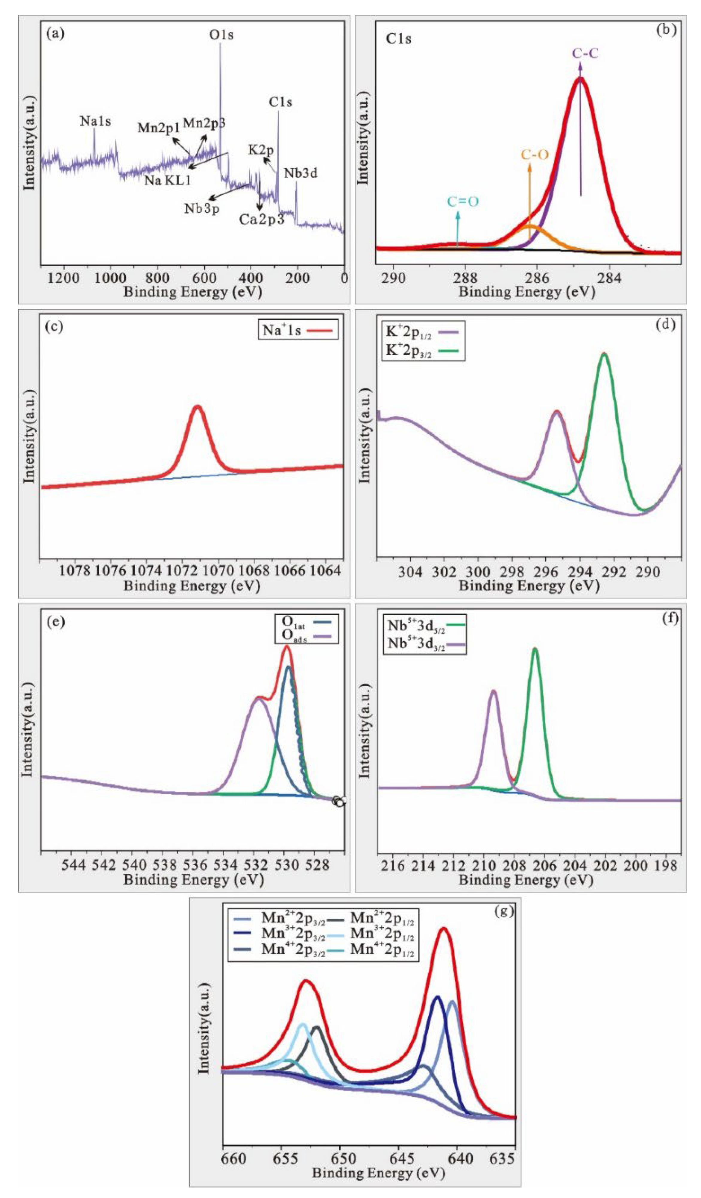
In order to investigate whether Mn entered the lattice of the KNN chalcogenide structure and to study the valence states of the elements, the binding energies of K, Na, Nb, O, and Mn of the KNMN coating and the valence states of each element were studied using the XPS technique, and the XPS profiles of the individual elements are shown in Figure 13. Since most of the Mn was eventually transformed into a higher valence state and because its radius was smaller than the interaction between K, Na, and Nb, the interaction between Mn and O was stronger than that between K, Nb, Na, and O. Therefore, the electron cloud density around oxygen decreased, leading to an increase in the K, Na, and Nb binding energy of the Mn-doped KNN films [16]. According to the results of the XPS fitting, peaks were found at 640.35 eV, 641.59 eV, and 642.7 eV and 651.95 eV, 653.11 eV, and 654.14 eV, as shown in Figure 13, which corresponded to Mn2+, Mn3+, and Mn4+, respectively [21]. The peak area indicated the content of a specific ion, but, with advantages, the exact area of the peak could not be accurately calculated and the height of the area was set according to the maximum value of the half-peak width. In contrast, the area of 640.35 eV was smaller than that of 641.59 eV and 642.7 eV, and so, it could be concluded that the first-introduced Mn2+ ions were mainly oxidized to higher valence ions at high temperature.
The presence of oxygen vacancies in the coating was due to the volatilization of alkaline ions at the A site, i.e., Na and K elements, while, at the B-site, Nb5+ ions were reduced to Nb4+ at high temperature, which generated oxygen vacancies, and the oxidation of oxygen vacancies generated vacancies of the main carriers; the oxidation reaction was as follows [30]:
It has been reported that the addition of Mn to KNN piezoelectric ceramics can replace both the A site and B site in sodium potassium niobate. When Mn2+ replaces the A site in sodium potassium niobate, the addition of Mn ions can further promote the consumption of cavities and reduce the volatilization of alkaline elements in the A site, further reducing the leakage current as well as oxygen vacancies in the coating [30].
In addition [21,35], the occupation of Mn2+ on the B site of the potassium sodium niobate coating can lead to more oxygen vacancies, while Mn2+ can be oxidized to a higher valence state through absorbing vacancies (Equations (2) and (3)). The oxidation of Mn2+ can effectively reduce the vacancies, allowing for the conversion of oxygen vacancies to lattice oxygen, which, in turn, leads to a decrease in the leakage current density, as well as the concentration of oxygen vacancies [30].
The three valence states of Mn ions also illustrated the idea that the doping of Mn ions could replace both the A and B sites in sodium potassium niobate. The oxygen vacancies of the coating mainly come from the volatilization of alkaline elements at the A site of sodium potassium niobate and the replacement of sodium potassium niobate with Mn2+ B sites, while the presence of Mn ions can reduce the consumption of vacancies and oxygen vacancies and the leakage current of the coating, thus, further improving the electrical properties of the coating.
4. Conclusions
The KNN and KNMN coatings were prepared using plasma spraying technology in the research, and the properties of the coatings were studied. The main conclusions were as follows: (1) The KNN and KNMN coatings had an orthoclase structure; the KNN coatings had an orthotropic phase and the KNMN coatings had a tetragonal phase structure. (2) The doping of the Mn ions could effectively promote the melting and the quality of the coating, and improved its mechanical properties. (3) The KNMN coating had better dielectric and ferroelectric properties; the dielectric constant and dielectric loss of the KNMN coating could be stabilized at 1700 and 0.01, respectively; the dielectric constant and dielectric loss of the KNN coating were stabilized at 900 and 0.08, respectively.
Author Contributions
R.G.: writing—original draft; investigation, and data curation. X.L.: supervision. W.G.: review and editing. Z.X.: review and editing. H.W.: editing. All authors have read and agreed to the published version of the manuscript.
Funding
The paper was financially supported by the general program of the National Natural Science Foundation of China (grant no. 52130509), the key basic research project of the Foundation Strengthening Plan (grant no. 2019-JCJQ-JJ-034, 2019-JCJQ-ZD-302), and the Innovation Capability Support Program of Shaanxi (no. 2021KJXX-38).
Conflicts of Interest
The authors declare no conflict of interest.
References
- Shibnath, S.; Sankaranarayanan, V.; Sethupathi, K. Band gap, piezoelectricity and temperature dependence of differential permittivity and energy storage density of PZT with different Zr/Ti ratios. Vacuum 2018, 156, 456–462. [Google Scholar]
- Sun, S.D.; Liu, H.; Fan, L.L.; Ren, Y.; Xing, X.R.; Chen, J. Structural origin of size effect on piezoelectric performance of Pb(Zr,Ti)O3. Ceram. Int. 2020, 47, 5256–5264. [Google Scholar] [CrossRef]
- Samanta, S.; Sankaranarayanan, V.; Sethupathi, K.; Rao, M.S.R. Enhanced ferroelectricity in PLZT ceramic by precise La-doping, minimizing pyrochlore phase and lead loss. Vacuum 2018, 157, 514–523. [Google Scholar] [CrossRef]
- Pereira, M.; Boerasu, I.; Gomes, M. Characterization of Nb-doped PZT (65/35/1) ferroelectric thin films deposited by pulsed laser ablation. Vacuum 2008, 82, 1379–1382. [Google Scholar] [CrossRef]
- Li, X.W.; Wang, H.X.; Shi, T.; Zhang, C.W.; Jiang, X.N.; Zhou, X.G.; Li, C. Efficient Preparation and Anticorrosion Mechanism of Superhydrophobic 7075 Aviation Aluminum Alloy. Rare Met. Mater. Eng. 2022, 51, 6–10. [Google Scholar]
- Coondoo, I.; Panwar, N.; Maiwa, H.; Kholkin, A.L. Improved piezoelectric and energy harvesting characteristics in lead-free Fe2O3 modified KNN ceramics. J. Electroceram. 2015, 34, 255–261. [Google Scholar] [CrossRef]
- Zhao, J.B.; Shao-Bo, Q.U.; Hong-Liang, D.U.; Zheng, Y.J.; Mo, W.D.; Yang, M. Actuality and Prospect of Potassium Sodium Niobium Based Lead-free Piezoelectric Ceramics. J. Air Force Eng. Univ. Nat. Sci. Ed. 2010, 11, 89–94. [Google Scholar]
- Li, X.W.; Yan, J.Y.; Yu, T.; Zhang, B.B. Versatile nonfluorinated superhydrophobic coating with self-cleaning, anti-fouling, anti-corrosion and mechanical stability. Colloids Surf. A Physicochem. Eng. Asp. 2022, 642, 128701. [Google Scholar] [CrossRef]
- Qiao, L.; Li, G.; Tao, H.; Wu, J.G.; Xu, Z.; Li, F. Full characterization for material constants of a promising KNN-based lead-free piezoelectric ceramic. Ceram. Int. 2019, 46, 5641–5644. [Google Scholar] [CrossRef]
- Venet, M.; Santa-Rosa, W.; Silva, P.; Peko, J.C.; Ramos, P.; Amorin, H.; Alguero, M. Selection and Optimization of a K0.5Na0.5NbO3-Based Material for Environmentally-Friendly Magnetoelectric Composites. Materials 2020, 13, 731. [Google Scholar] [CrossRef] [Green Version]
- Liang, W.F.; Wu, W.J.; Xiao, D.Q.; Zhu, J.G. Effect of nonstoichiometry on the phase transitions and properties of(K0.465Na0.465Li0.07)(Nb0.95Sb0.05)O3 lead-free piezoelectric ceramics. J. Funct. Mater. 2012, 43, 126–129. [Google Scholar]
- Bassi, M.; Tripathi, S.L.; Verma, S. Analysis and Design of high-K Material Nanowire Transistor for Improved Performance. In Proceedings of the IEEE 10th Annual Information Technology, Electronics and Mobile Communication Conference (IEMCON), Vancouver, BC, Canada, 17–19 October 2019; pp. 613–618. [Google Scholar]
- Hong, X.; Wei, R.; Wu, X.; Shi, P. Effect of Mn doping on structures and properties of chemical solution deposited lead zirconate titanate thick films with (100) preferential orientation. J. Appl. Phys. 2013, 114, 317. [Google Scholar]
- Qi, Z.; Whatmore, R.R. Hysteretic properties of Mn-doped Pb(Zr,Ti)O3 thin films. J. Eur. Ceram. Soc. 2004, 24, 277–282. [Google Scholar]
- Huang, X.; Peng, J.; Zeng, J.; Zheng, L.; Li, G.; Karaki, T. The high piezoelectric properties and high temperature stability in Mn doped Pb(Mg0.5W0.5)O3-Pb(Zr,Ti)O3 ceramics. Ceram. Int. 2019, 45, 6523–6527. [Google Scholar] [CrossRef]
- Geng, W.; Chen, X.; Pan, L.; Qiao, X.J.; He, J.; Mu, J.L.; Hou, X.J.; Chou, X.J. Improved crystallization, domain, and ferroelectricity by controlling lead/oxygen vacancies in Mn-doped PZT thin films. Mater. Charact. 2021, 176, 111131. [Google Scholar] [CrossRef]
- Eml, A.; Ya, B.; Jys, A. Effects of Mn doping on BaTiO3 thin films grown on highly oriented pyrolytic graphite substrates-ScienceDirect. Curr. Appl. Phys. 2020, 20, 755–759. [Google Scholar]
- Peng, W.; Li, L.; Yu, S.; Yang, P.; Xu, K.L. Dielectric properties, microstructure and charge compensation of MnO2-doped BaTiO3-based ceramics in a reducing atmosphere. Ceram. Int. 2021, 47, 29191–29196. [Google Scholar] [CrossRef]
- Zhang, Y.; Meng, X.; Huang, F.; Hu, C.P.; Tan, P.; Wang, Y.; Huang, X.L.; Zhou, Z.X.; Tian, H. Effects of Mn-doping on anti-fatigue and anti-leakage current characteristics in KNN single crystals. Appl. Phys. Lett. 2021, 118, 042903. [Google Scholar] [CrossRef]
- Wang, L.; Wei, R.; Peng, S.; Wu, X.Q. Structures, electrical properties, and leakage current behaviors of un-doped and Mn-doped lead-free ferroelectric K0.5Na0.5NbO3 films. J. Appl. Phys. 2014, 115, 1400. [Google Scholar] [CrossRef]
- Abazari, M.; Safari, A. Effects of doping on ferroelectric properties and leakage current behavior of KNN-LT-LS thin films on SrTiO3 substrate. J. Appl. Phys. 2009, 105, 241. [Google Scholar] [CrossRef]
- Sharma, S.; Kumar, A.; Gupta, V.; Tomar, M. Dielectric and ferroelectric studies of KNN thin film grown by pulsed laser deposition technique. Vacuum 2019, 160, 233–237. [Google Scholar] [CrossRef]
- Jia, Z.; Huang, C.; Sekino, T.; Kim, S.H.; Lee, S.W. Residual stress determination in plasma sprayed Al2O3 coatings. J. Ceram. Process. Res. 2008, 9, 317–320. [Google Scholar]
- Fang, S.; Zhao, H.Y.; Liu, C.G.; Zhong, X.H.; Zhuang, Y.; Ni, J.X.; Tao, S.Y. Dense yttria-stabilized zirconia coatings fabricated by plasma spray-physical vapor deposition. Ceram. Int. 2017, 43, 2305–2313. [Google Scholar]
- Dong, X.Y.; Luo, X.T.; Zhang, S.L.; Li, C.J. A Novel Strategy for Depositing Dense Self-fluxing Alloy Coatings with Sufficiently Bonded Splats by One-Step Atmospheric Plasma Spraying. J. Therm. Spray Technol. 2020, 29, 173–184. [Google Scholar] [CrossRef]
- Waldbillig, D.; Kesler, O. Effect of suspension plasma spraying process parameters on YSZ coating microstructure and permeability. Surf. Coat. Technol. 2011, 205, 5483–5492. [Google Scholar] [CrossRef]
- Chen, S.; Tan, C.K.I.; Yao, K. Potassium-Sodium Niobate-Based Lead-Free Piezoelectric Ceramic Coatings by Thermal Spray Process. J. Am. Ceram. Soc. 2016, 99, 3293–3299. [Google Scholar] [CrossRef]
- Chen, S.; Tan, C.; Tan, S.Y.; Guo, S.F.; Zhang, L.; Yao, K. Potassium sodium niobate (KNN)-based lead-free piezoelectric ceramic coatings on steel structure by thermal spray method. J. Am. Ceram. Soc. 2018, 101, 5524–5533. [Google Scholar] [CrossRef]
- Zhou, L.L.; Li, X.W.; He, D.Y.; Guo, W.L.; Huang, Y.F.; He, G.C.; Xing, Z.G.; Wang, H.D. Study on Properties of Potassium Sodium Niobate Coating Prepared by High Efficiency Supersonic Plasma Spraying. Actuators 2022, 11, 28. [Google Scholar] [CrossRef]
- Song, Y.Y.; Huang, Y.F.; Guo, W.L.; Zhou, X.Y.; Xing, Z.G.; He, D.Y.; Lv, Z.L. Electrical Properties of Li+-Doped Potassium Sodium Niobate Coating Prepared by Supersonic Plasma Spraying. Actuators 2022, 11, 39. [Google Scholar] [CrossRef]
- Tnase, L.C.; Abramiuc, L.E.; Popescu, D.G.; Trandafir, A.M.; Apostol, N.G.; Bucur, I.C.; Hrib, L.; Pintilie, L.; Pasuk, I.; Trupina, L.; et al. Polarization Orientation in Lead Zirconate Titanate (001) Thin Films Driven by the Interface with the Substrate. Phys. Rev. Appl. 2018, 10, 034020. [Google Scholar] [CrossRef]
- Sun, Y.; Guo, F.; Lu, Q.; Zhao, S.F. Improved Ferroelectric Photovoltaic Effect in Mn-doped Lead-free K0.5Na0.5NbO3 Films. Ceram. Int. 2018, 44, 13994–13998. [Google Scholar] [CrossRef]
- Wang, L.; Wei, R.; Goh, P.C.; Goh, P.C.; Yao, K.; Shi, P.; Wu, X.Q.; Yao, X. Structures and electrical properties of Mn- and Co-doped lead-free ferroelectric K0.5Na0.5NbO3 films prepared by a chemical solution deposition method. Thin Solid Film. 2013, 537, 65–69. [Google Scholar] [CrossRef]
- Won, S.S.; Lee, J.; Venugopal, V.; Venugopal, V.; Kim, D.J.; Lee, J.; Kim, I.W.; Kinggon, A.L.; Kim, S.H. Lead-free Mn-doped (K0.5,Na0.5)NbO3 piezoelectric thin films for MEMS-based vibrational energy harvester applications. Appl. Phys. Lett. 2016, 108, 1131. [Google Scholar] [CrossRef]
- Wang, L.Y.; Ren, R.; Shi, P.; Chen, X.F.; Wu, X.Q.; Yao, X. Enhanced ferroelectric properties in Mn-doped K0.5Na0.5NbO3 thin films derived from chemical solution deposition. Appl. Phys. Lett. 2010, 97, 209. [Google Scholar] [CrossRef]
Figure 1.
Schematic diagram of the plasma spraying process.

Figure 2.
KNN and KNMN powder particle size.

Figure 3.
(a) Three-dimensional morphology of KNN coating. (b) Three-dimensional morphology of KNMN coating.
Figure 3.
(a) Three-dimensional morphology of KNN coating. (b) Three-dimensional morphology of KNMN coating.

Figure 4.
(a) Cross-sectional morphology of KNN coating. (b) Cross-sectional morphology of KNMN coating. (c) EDS surface scan of KNMN coating.
Figure 4.
(a) Cross-sectional morphology of KNN coating. (b) Cross-sectional morphology of KNMN coating. (c) EDS surface scan of KNMN coating.
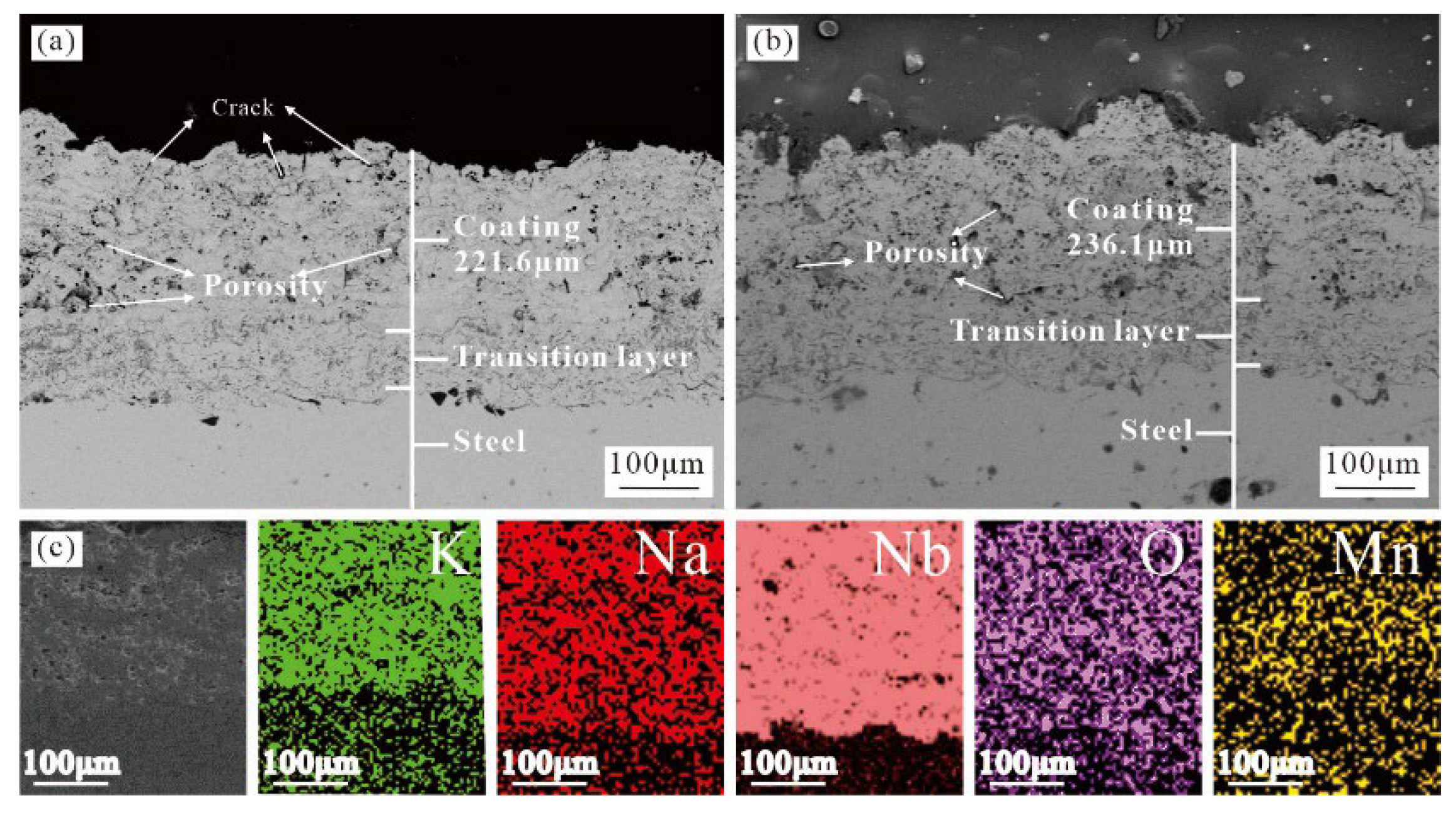
Figure 5.
TEM/EDX surface scan elements of KNMN coating.

Figure 6.
X-ray energy spectrum analysis of KNMN coating.

Figure 7.
(a) XRD patterns of KNN and KNMN powders. (b) 44°–47° XRD extended patterns.

Figure 8.
(a) XRD patterns of KNN, KNMN coatings. (b) 44°–47° XRD extended patterns.
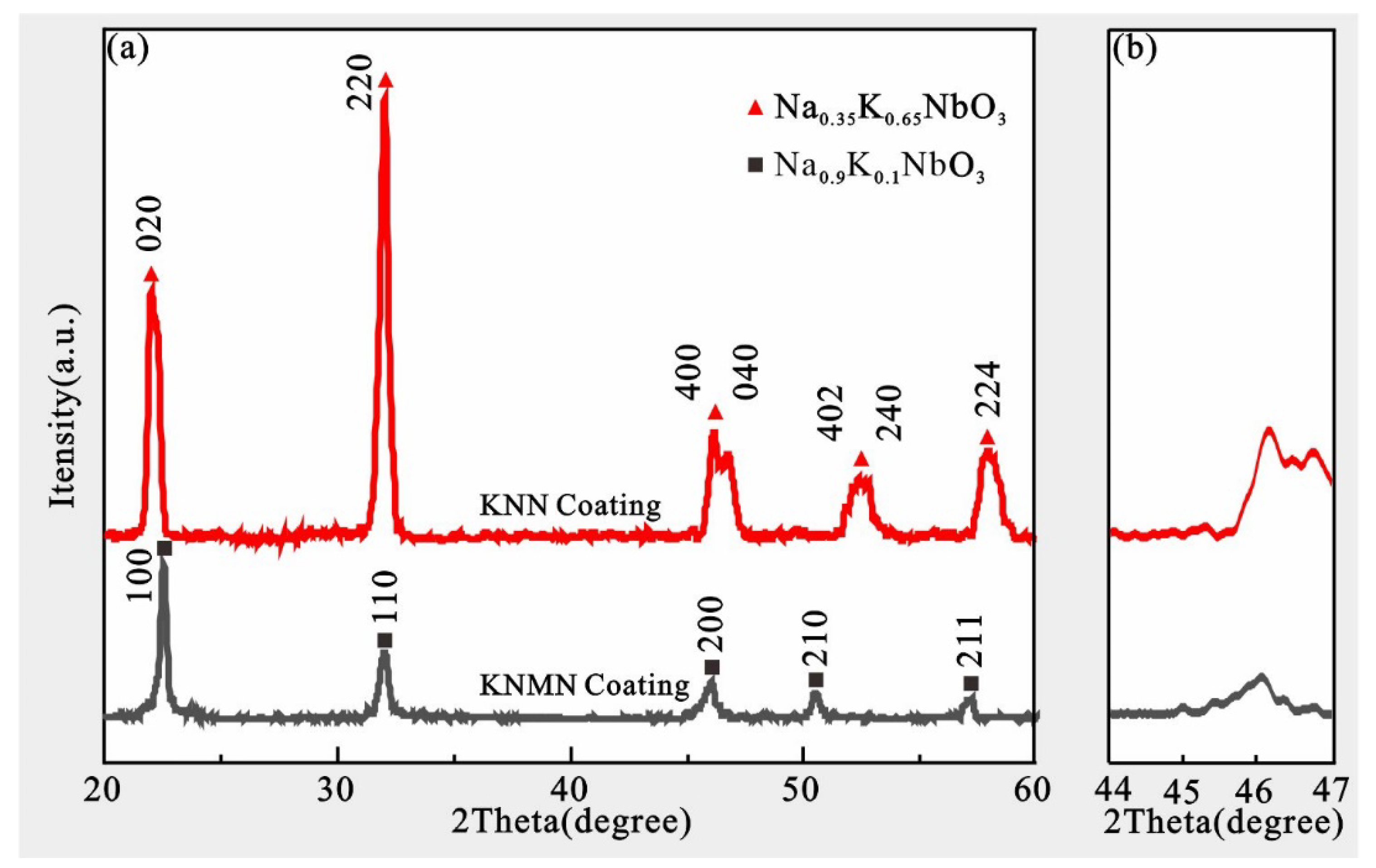
Figure 9.
(a) Microhardness of KNN and KNMN transition layer to coating. (b) Average hardness of KNN and KNMN coatings.
Figure 9.
(a) Microhardness of KNN and KNMN transition layer to coating. (b) Average hardness of KNN and KNMN coatings.
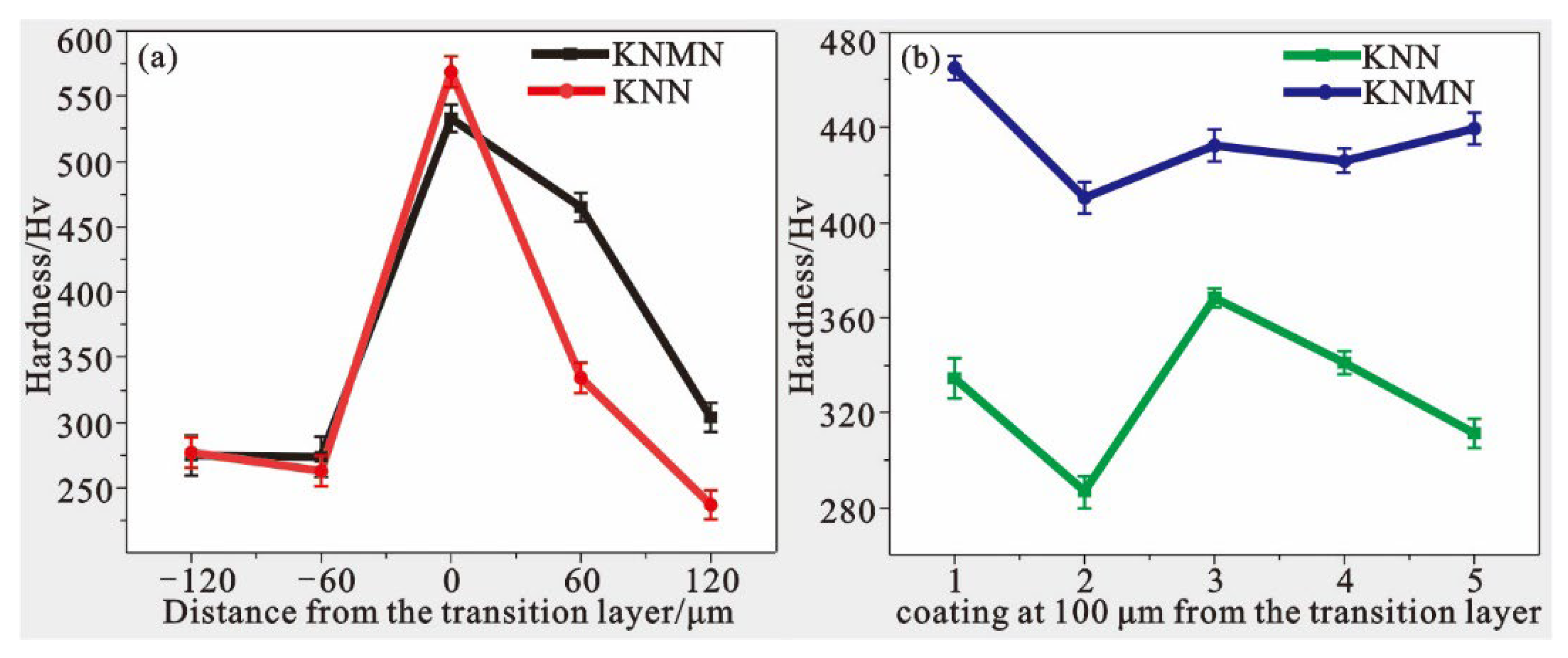
Figure 10.
Bond strength of KNN and KNMN coatings.

Figure 11.
Dielectric spectrum of KNN and KNMN coatings.
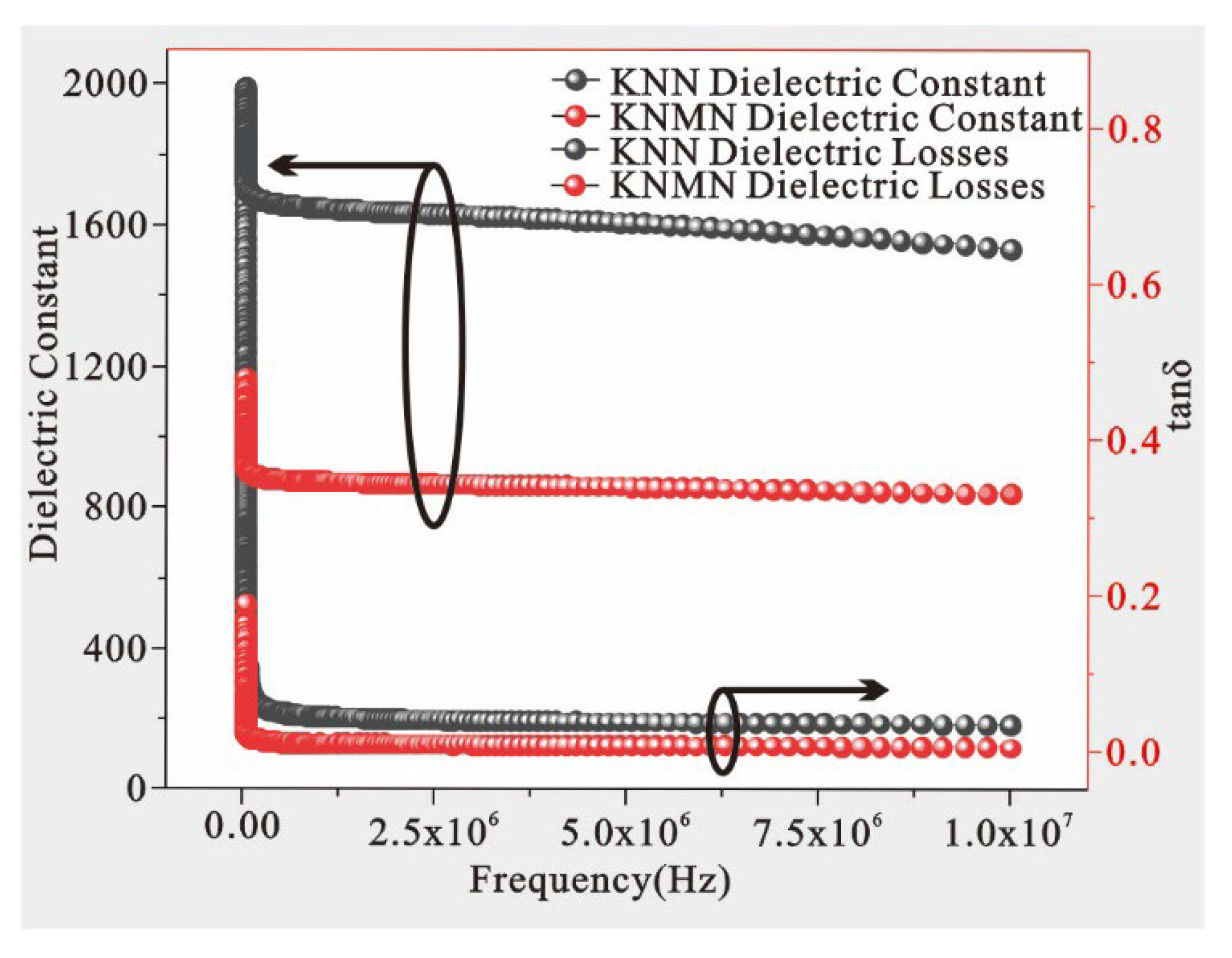
Figure 12.
Electric hysteresis lines of KNN and KNMN coatings.
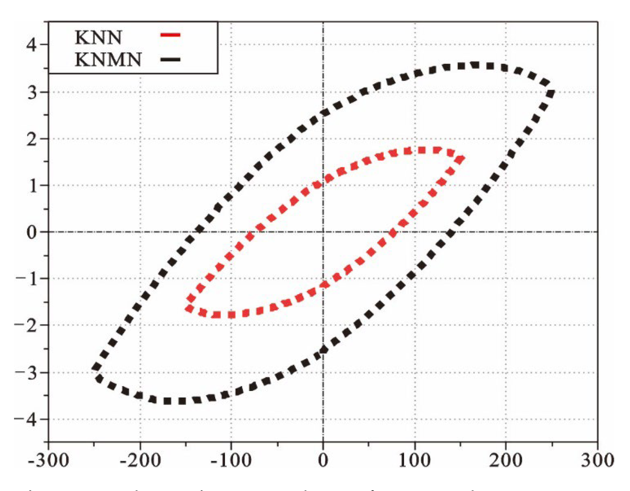
Figure 13.
XPS pattern analysis of KNMN coating: (a) XPS full spectrum; (b) C1spectrum; (c–g) K, Na, Nb, O, and Mn XPS mapping.
Figure 13.
XPS pattern analysis of KNMN coating: (a) XPS full spectrum; (b) C1spectrum; (c–g) K, Na, Nb, O, and Mn XPS mapping.

Table 1.
Spraying process parameters.
| Process Parameters | |
|---|---|
| Ar gas flow (m3/h) | 50 |
| Spraying voltage (V) | 96 |
| H2 gas flow (m3/h) | 8 |
| Spraying current (A) | 400 |
| Spraying distance (mm) | 100 |
| Powder feeding speed (g/min) | 20 |
Table 2.
Element contents in the coatings.
| Element | K | Na | Nb | O | Mn | C |
|---|---|---|---|---|---|---|
| wt% | 11.27 | 2.48 | 60.26 | 24.93 | 0.58 | 0.48 |
| at% | 10.9 | 4 | 24.5 | 58.69 | 0.4 | 1.51 |
Publisher’s Note: MDPI stays neutral with regard to jurisdictional claims in published maps and institutional affiliations. |
© 2022 by the authors. Licensee MDPI, Basel, Switzerland. This article is an open access article distributed under the terms and conditions of the Creative Commons Attribution (CC BY) license (https://creativecommons.org/licenses/by/4.0/).
Share and Cite
MDPI and ACS Style
Gao, R.; Guo, W.; Wang, H.; Li, X.; Xing, Z. Effect of Mn Doping on the Microstructure and Electrical Properties of Potassium Niobate Ceramics Using Plasma Spraying. Actuators 2022, 11, 343. https://doi.org/10.3390/act11120343
AMA Style
Gao R, Guo W, Wang H, Li X, Xing Z. Effect of Mn Doping on the Microstructure and Electrical Properties of Potassium Niobate Ceramics Using Plasma Spraying. Actuators. 2022; 11(12):343. https://doi.org/10.3390/act11120343
Chicago/Turabian StyleGao, Rui, Weiling Guo, Hongxing Wang, Xuewu Li, and Zhiguo Xing. 2022. "Effect of Mn Doping on the Microstructure and Electrical Properties of Potassium Niobate Ceramics Using Plasma Spraying" Actuators 11, no. 12: 343. https://doi.org/10.3390/act11120343
Note that from the first issue of 2016, this journal uses article numbers instead of page numbers. See further details here.