1. Introduction
The acoustics of a space is seldom considered when designing a bar or a restaurant. Even the noise intrusion from the bar into adjoining spaces is not recognized and attended to, only if there are complaints. Many small music venues do not undertake a proper acoustical study and only implement minor fixes after the fact. Acoustical consultants face myriad obstacles when requested to provide design guidelines during the initial stages of the venue planning. Cost and implementation difficulties are excuses used to thwart the acousticians. Similarly, when the small music venues face acoustical deficiencies after the facilities are constructed, the owners do not always offer a free hand to the acousticians to satisfactorily resolve the acoustical concerns.
In contrast to the conventional modus operandi, two partners with strong musical background, decided to convert a defunct deli into a music room/bar-restaurant facility at a major intersection in Toronto. As musicians, they understood the seriousness of their plans from an acoustical perspective. The acousticians were given total freedom to provide proper design solutions from different aspects of acoustics such as room acoustics and noise separation.
The two spaces were designed using conventional prediction schemes and implementation details were appropriately prescribed. Preliminary details and results from site measurements were presented in Ramakrishnan and Dumoulin [
1].
Vigeant
et al. investigated different test methods to determine the JND (Just Noticeable Difference) for the clarity metric C
80 [
2]. The current case study has evaluated the relative errors of different acoustic metrics by using the subjective limen calculations. The JND evaluation of Reference [
3] is somewhat similar to the current investigation.
Patania
et al. investigated, through simulation, the acoustic of a music hall in a heritage building in University of Catania, Italy and provided methods to improve its acoustic quality [
3]. Orlowski conducted a series of measurements to evaluate the reverberation time and strength in a number of music rooms [
4]. Nocera
et al. investigated the lecture hall of steel construction and provided methods to improve its acoustic quality [
5]. Similar investigations were undertaken in the current study to provide suitable acoustical designs for the conversion of a delicatessen into a music room.
The two facilities were constructed and became operational in early 2015. Detailed site measurements were conducted and the finished facility was remodeled using ODEON software [
6]. The results of the comparisons between simulation and site measurements are presented in this paper. Detailed results of the simulation are also presented in this paper.
2. Background
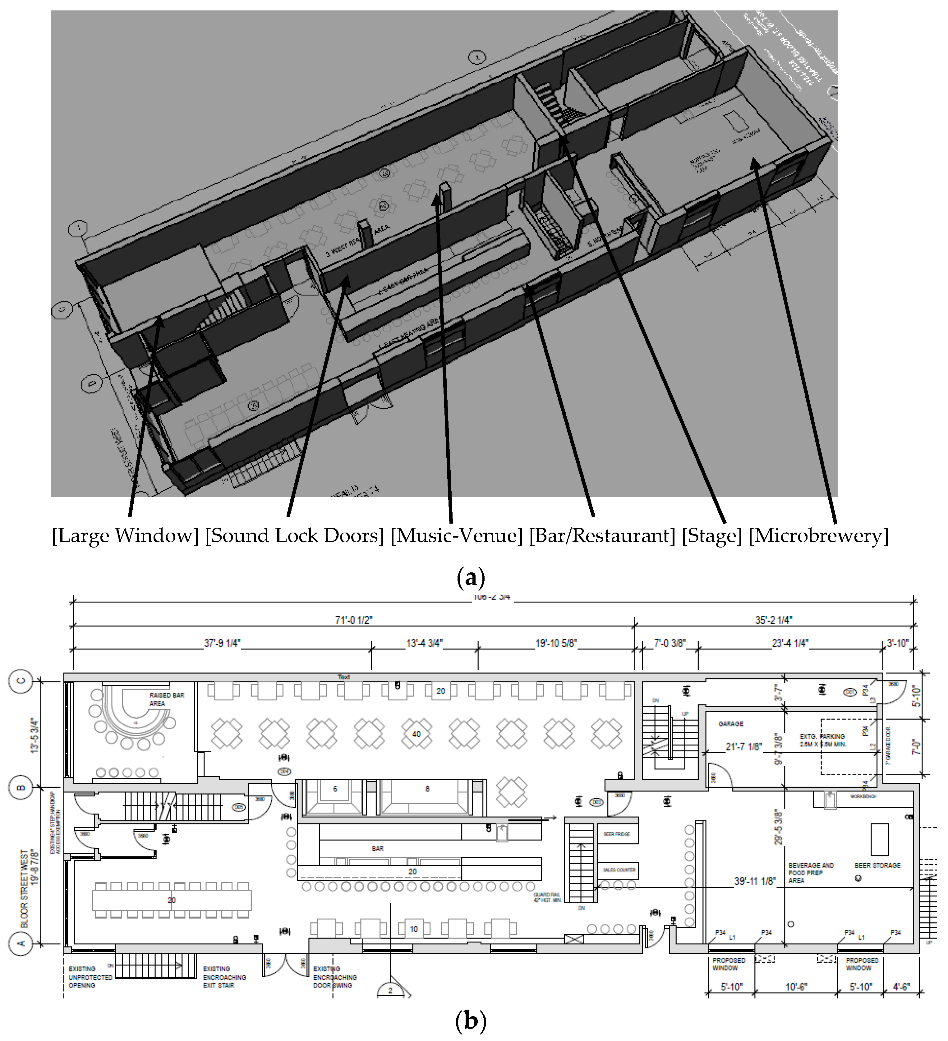
The proposed, but preliminary, lay out details of the music venue/bar-restaurant, on Bloor Street, Toronto, are shown in
Figure 1. The unit was divided into two spaces along its north-south axis. The western portion was designed as a music room, with an approximate volume of 230 cu.m, that would provide a performance space for a solo artist to a Jazz combo to a small rock band. The eastern part was designed as a regular bar/dining area. The bar music can be loud, while the music room can be pianissimo to forte depending on the type of performance. The plans also called for a microbrewery unit at the north end of the facility.
Music Venue/Bar Requirements
Two different types of needs were considered during the design: (a) Unreinforced concerts with acoustical instruments; and (b) music using sound reinforcement system. The main acoustical requirements were: (i) adequate loudness in every part of the room; (ii) uniform distribution of sound pressure levels; (iii) optimum reverberation for music; (iv) free from acoustical defects (such as echoes); and (v) low background noise levels and vibration.
The acoustical parameters used to evaluate the quality of the venue acoustics were: reverberation time (T
30); and clarity (C
80). It must be noted that only the above two metrics and expected sound level distribution were investigated for preliminary design details of the music venue. The optimum acoustical parameters for the venue according ISO standards and well known recommendations are summarized in
Table 1 below [
7,
8,
9,
10,
11].
In addition, adequate acoustical separation must be provided between the bar and the music venue. The bar sound levels must be controlled with a limiter and overall sound levels in the bar-restaurant area should not exceed 85 dBA and 90 dB. It can be seen therefore that an Apparent Sound Transmission Class (ASTC) of around 50 is an adequate separation for the construction between the music venue and the bar.
3. Proposed Design
The microbrewery is located along the north end of the unit. The east wall faces a side street and there is a gap along the west wall. In addition the second level of the complex has three rental apartments. And hence, it must be pointed out that the interior acoustical design is as important as the design of appropriate separation so that the noise intrusions can be kept to a minimum. Finally, the HVAC system noise levels must be adequately silenced. The details of the design are outlined in the following sections.
3.1. Interior Acoustical Design
The music venue is long and narrow with a large window on the south wall. The stage area is at the north end with the musicians on an elevated platform. It will be utilized for three different events: solo musician (with and without amplification); a small group such as a jazz band (with and without amplification); and a rock band (with amplification).
The three event scenarios were modeled in the acoustical software. The results showed that the solo musician might need some amplification. Jazz Band can be loud enough without amplification. The Rock band uses amplification. Since the space is narrow and long, it needs diffusers to aid in the propagation and assist in the diffusivity of the sound. Approximately 50 square metres of diffusers were to be applied in the acoustical simulations and a few diffuser options, as shown in
Figure 2 below, were proposed. One of the main requirements is to install heavy valour drapes, operable, over the south window and behind the stage for two reasons: (a) to prevent echoes from the window; and (b) to add acoustical absorption to the room when sound amplification is used. Moveable absorbing curtains and a treated ceiling were recommended for the stage area in order to reduce the risks of acoustical feedback when microphones are used for sound reinforcement.
The location of the speakers and sub-woofers are very critical to overcome low-frequency modal distribution in the music room and appropriate locations were recommended.
Finally, the speakers for the Bar music are to be hung by spring hangers from the main ceiling joist and the levels are controlled to be less than 85 dBA and 90 dB (linear). The limiter to be used for the bar music must include a microphone to measure the bar noise levels.
3.2. Acoustical Separation
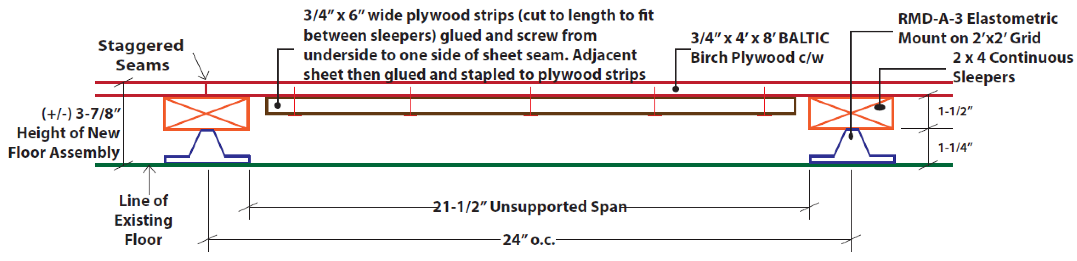
A floating floor assembly was used for the music venue. Baltic birch board, ¾” thick, was floor mounted on rubber-in-shear mounts as shown below in
Figure 3.
Two wall assemblies will separate the music venue and the bar. Each wall assembly is two layers of drywall (5/8′′ thick) and is on separate metal studs. The spacing between the studs was chosen to fit the space. The air-gap between the two studs is filled with batt insulation. There are two wall assemblies for the music venue: one that separates the bar and the other one is next to the exterior wall. Both the wall assemblies, including the studs were placed on the floating floor. The studs of the wall assembly next to the exterior wall were connected through partition supports such as sway braces.
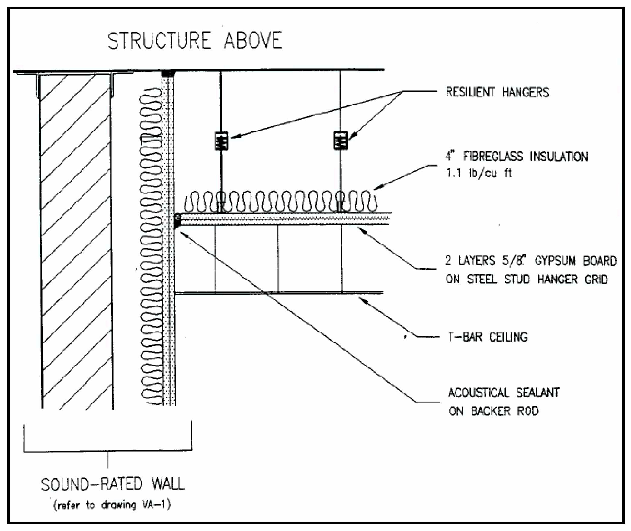
The ceiling of the two spaces were designed as a membrane system to provide separation between the two spaces as well as to adequately separate the spaces from the apartments above. Details of typical membrane system are shown in
Figure 4 below. Note: The T-Bar system shown in
Figure 4 was not part of the current design. The music venue’s ceiling consisted of a 3-layer gypsum board with each layer’s taping staggered from the adjacent layers and were connected to the main slab through resilient hangars. On the other hand, the celling of the bar-restaurant, due to space limitation, consisted of a double layer gypsum board construction and were connected to the slab above through resilient “z” channels.
The music venue and the bar share two sets of doors, one near the stage of the music venue and the other is near the raised portion of the music venue, as shown in
Figure 1. Both doors, of each set, was solid core and one of them had an STC 47 rating. Finally, the HVAC system details were assessed and appropriate silencers were recommended so the music venue ambient sound levels were less than NC-35 (NC is Noise Criterion Curves).
A few images of the completed music room are shown in
Figure 5 below. Wall design as diffusers and the location of the stage speakers are highlighted in
Figure 5.
The diffusers correspond to a relaxed architectural adaptation of maximum length sequence diffusers with vertical and horizontal wells. While perfectly uniform diffusion was not needed, the main objective for these diffusers was to diffuse early lateral reflections. The location of the speakers and sub-woofers are very critical to control the acoustic energy delivered from speakers to room modes. In order to limit the first three orders of the axial modes (for the venue’s width and height axes) to be energized, appropriate locations of the subwoofers were recommended—25% of the room width from each wall and elevated at 25% of the room height from the floor, which correspond to the null locations for the second-order standing waves. Simple room acoustic simulations were not undertaken since the main frequencies around 125 Hz were below the Schroeder cut-of frequency limit for the simulation software. Note: If one needs an accurate representation in low frequencies, FEM (Finite Element Modelling) simulation would have to be undertaken, which is beyond the scope of the current study.
4. Acoustical Modelling
The final design of the room was modelled in ODEON simulation tool for comparison purposes [
2]. Two scenarios were applied to generate acoustical metrics along a grid, at a height of 1.5 m, representing the audience space. The audience space of the music room consisted of two areas: (a) the audience, seated, in the northern half; and (b) the audience, standing, near the southern portion. The grid simulations were undertaken for the fully occupied room and for the empty room. In addition, four individual locations were chosen to generate the acoustical parameters for an empty room so as to provide comparison results with site measurements, to be discussed subsequently in
Section 6. The results of the reverberation time from the site measurements were used to calibrate the simulation models.
A large set of parameters were generated by simulation as well as calculations from impulse measurements. Detailed definitions and acceptable range of values for the acoustical parameters can be found in Barron [
10] and Rossing [
11]. The following parameters will be evaluated and discussed in this paper. Note: The relationship between subjective parameters and objective acoustical metrics such as T
60, EDT, C
80, and T
s have been dealt with in detail by a number of researchers and can be found in References [
9,
10,
11]. And hence only their brief definition are highlighted below.
Reverberation Time, T60—represents the amount of reverberance of the space;
Early Decay Time, EDT—represents the amount of reverberance of the space and is better correlated with reverberance than RT60;
Clarity, C80—describes the degree of perception of the details of the performance;
Centre Time, Ts—describes the balance between early and late sound and hence evaluates the balance between clarity and reverberance;
SPL (Sound Pressure Level) Variation—describes how the sound is distributed throughout the space. The absolute values are not critical and one should look only at its variation.
Finally, the echo potential is evaluated by using the methods of Dietsch and Kraak [
12]. The simulations of the room requires acoustical parameters such as absorption coefficients of the interior materials. These values are obtained from the database of the simulation software as well as published materials such as those provided by Adelman-Larson
et al. [
13]. The scattering coefficients, in particular for wood diffuser walls and audience were obtained from Zeng
et al. [
14]. The above values were adjusted while calibrating the simulation models with measured data from impulse measurements (
Section 5.3).
A set of sample results, RT
60 (based on T(30) averaged T(30), and SPL variation, of the simulations are presented in
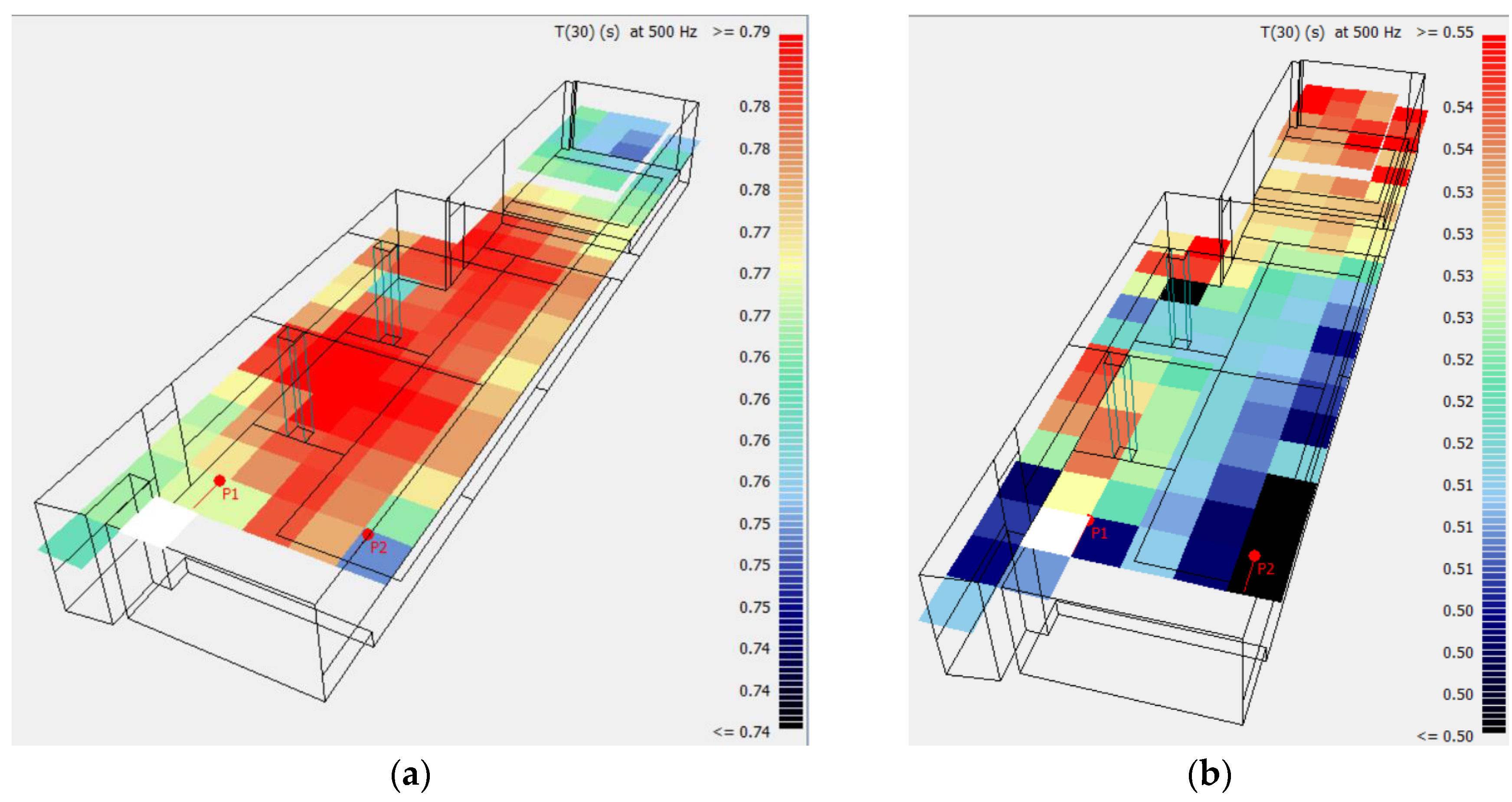
Figure 6 through 8. Reverberation time results for the full and empty rooms, at 500 Hz, are shown in
Figure 6. The variation across the room is insignificant. The reverberation time reduced from 0.8 s for the empty room to 0.55 s for the full room. The reduced reverberation falls within the design goal set for the music room with sound amplification.
The SPL variation at 500 Hz for the fully occupied and empty room scenarios are shown in
Figure 7. In the case of a small group with amplification only on the stage, the SPL variations are of the order of 9 dB for the fully occupied room and 7 dB for the empty room. However, the SPL variation for the front half of the room is 3.5 dB for the full room and 2.5 dB for the empty room. The lack of uniform distribution near the back of the music room was highlighted during the initial design and it was recommended that sound amplification was to be implemented. The final plan of the music room included two ceiling mounted speakers, in the centre of the room and provided additional sound for the back portion of the room, as shown in
Figure 5d.
The results of average reverberation time is presented in
Figure 8 below. The variation of the reverberation time is similar to that of 500 Hz. The averaged value reduced from 0.8 s (empty room) to 0.5 s (fully occupied room). The reduced reverberation falls within the design goal set for the music room with sound amplification.
Finally, the simulation results showed the following values, of the remaining acoustical parameters, for a fully occupied room at 500 Hz: (a) C80 ranged between 3 dB and 8 dB; (b) Ts was between 25 ms to 65 ms; and (c) EchoDietsch values were between 0.39 and 0.49. And hence, it can be concluded that the music room had been designed to provide more than satisfactory acoustical conditions. Note: EchoDietsch values have to be higher than 0.9 to cause any concerns.
5. Site Measurements
The music room/bar-restaurant has been in operation since the spring of 2015 and hence, it was possible to conduct site measurements. Three sets of measurements were conducted: (a) ambient measurements within the music room; (b) noise reduction between the bar-restaurant and the music room; and (c) Impulse response measurements within the music room. The results of the three measurements are described below.
5.1. Acoustical Separation
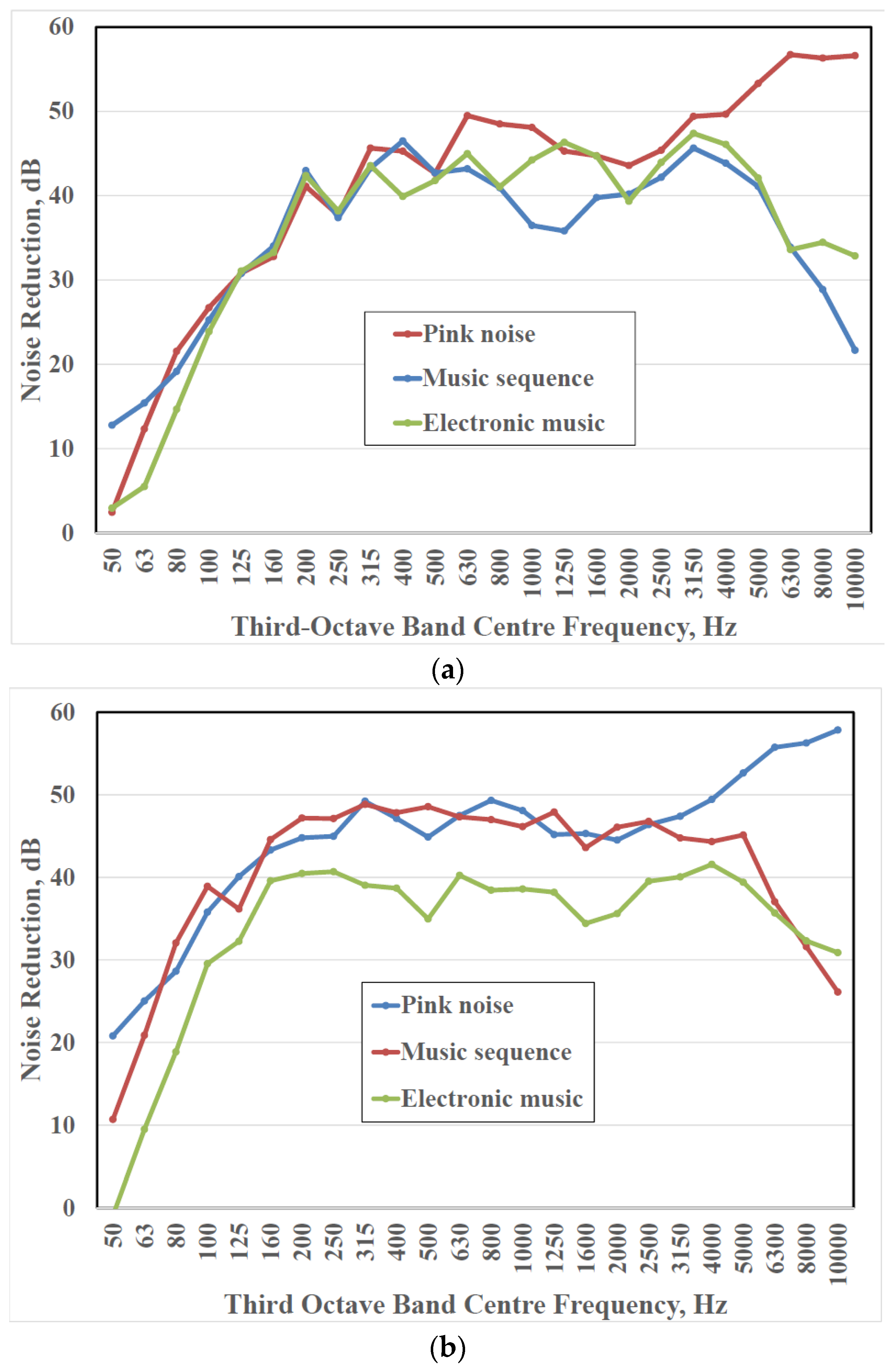
The acoustical separation between the bar-restaurant and the music room was established through measurements. Three potential noise paths existed between the two spaces: (a) through the separating walls; (b) through the double doors (two sets); and (c) through the ceiling. Three different sound sequences were played through the speaker system of the bar-restaurant: (i) 30 s of pink noise; (ii) 90 s of electronic music; and (iii) 120 s of a musical sequence. The sound sequences were played at a high 90 to 95 dBA level. The sound sequences were measured at two locations inside the bar-restaurant as well as at two locations inside the music room. The average noise reduction levels were calculated and the results are presented in
Figure 9 below.
It can be seen, from
Figure 9 that between ASTC (Apparent Sound Transmission Class) 45 to ASTC 50 noise transmission loss has been provided by the acoustical separation. The northern portion is seen to have provided high transmission loss values compared to the southern portion of the separation. Even higher transmission loss would have been obtained, if not for the following reasons.
- (a)
The music room is separated from the bar-restaurant by a sound lock with two solid-core wood doors. One of them is rated as an STC-47 door. The second door is a simple solid-core wood door. The STC-47 door, of the door-set in the middle of the room, has started to warp. The bottom door seal of the second door of the same set has worn out and does not exist anymore. And hence, the leakage though the southern doors was strongly noticeable. In contrast, the northern doors were seen to operate satisfactorily.
- (b)
The southern portion of the music room has a large window and hence traffic noise from a major street (Bloor Street) could have interfered with the measurements, in particular at low frequencies for the longer musical and electronic sequences.
The acoustical separation would have matched the design goal of ASTC 50, if the sound lock door along the southern portion performed as designed. Finally, the walls and the ceiling were observed to perform as per the design.
5.2. Ambient Sound
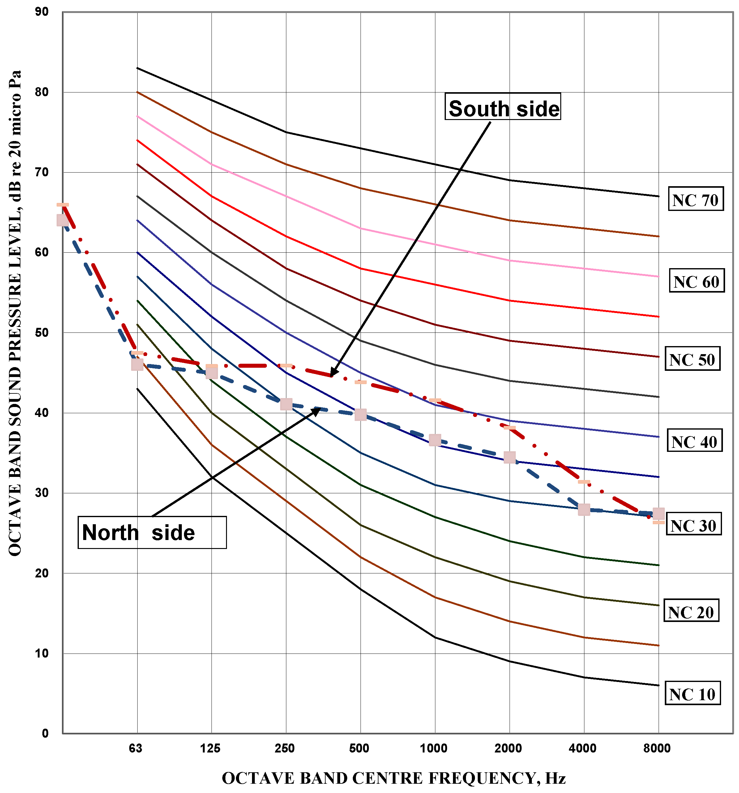
The background levels were measured inside the music room at two locations and the results are shown in
Figure 10 below.
The HVAV system was designed with silencers so that the ambient sound levels inside the music room will be less than NC-35 (NC: Noise Criterion Contour). The results of
Figure 10 show that along the northern portion, near the stage, the sound levels are less than or equal to NC-35. However, the southern portion, near the return air grille, has sound levels between NC-35 and NC-40. It was observed that the sound levels decreased substantially if the large return air grille was removed. And hence, it can be seen that the flow speed across the return air grille is high as well as the current grille needs to be replaced with a quieter grille.
5.3. Music Venue Acoustics
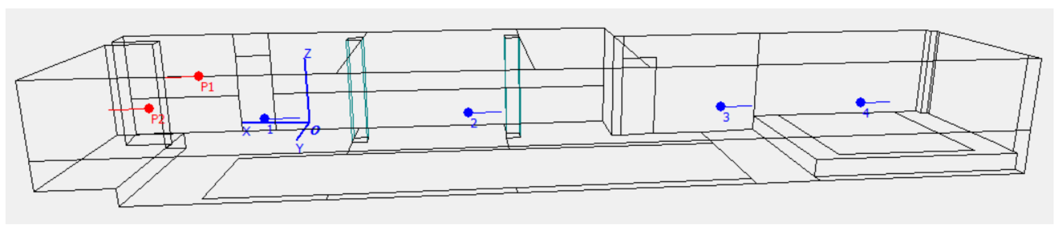
The interior acoustical performance of the music room was evaluated from impulse response measurements. The source locations and receiver locations are identified in
Figure 11 below. The red points P1 and P2 are the two speakers located on the stage ceiling (as per our original design guidelines) and were used to generate sine-sweep signals. The four blue points were the receiver locations (1.5 m above the floor), where the impulse responses were measured.
The impulse response measurements were analyzed using the ISO 3382 Standard procedures [
7,
8]. The results of the evaluations are presented in
Table 2 below. Six acoustical parameters—Early Decay Time, EDT; Reverberation Time, T(30); Centre Time, T
s; Sound Pressure Level, SPL; Clarity, C
80; and Echo Potential, EchoDietsch are analyzed for the current case study. The various metric values at five frequency bands (250 Hz through 2000 Hz) were averaged and presented in
Table 2.
The averaged results of the acoustic metrics were shown in
Table 2. The following observations can be gleaned from the results of
Table 2.
- (A)
EDT and T(30) variations are not significant and the values are well within the design goals;
- (B)
EDT at Location 1 is low since it is closest to the source;
- (C)
The centre time Ts, vaues are well below 100 ms;
- (D)
The SPL variation is not too large and hence additional rear area amplification may be required. The above point was highlighted in our original design specification;
- (E)
Clarity, C80 values are well above 0 dB and is acceptable;
- (F)
Echo potential values are well below 0.9 and hence echo is not a concern.
The main conclusion of the room acoustical measurements is that the music room performs satisfactorily and the original design guidelines have been satisfied adequately.
6. Comparison between Simulation and Measurements
The finished music room was remodeled using a simulation software, whose results were presented in
Section 4. Four receiver positions were chosen with two speaker (sound source) locations, as shown in
Figure 12 and the simulation were reevaluated. Sine-seep measurements were conducted in the music room, using the same sound source-receiver location combinations. The same acoustical metrics, as that of the simulation computations, were evaluated from the measured impulse responses as discussed in
Section 5.3.
The accuracy rating of the chosen acoustical parameters was determined by calculating the relative errors between measurements and simulations. Details of the evaluation process of the relative error can be found in Shiokawa
et al. and Vorlander [
15,
16]. Shiokawa
et al., surveyed eleven European concert halls and determined the relative errors for six acoustical parameters [
15]. Vorlander’s study involved with the simulation and measurement of a 273 seat auditorium in Braunschweig, Germany [
16]. Fourteen different programs were applied to simulate the auditorium and site measurements were conducted to evaluate eight acoustical parameters. Relative errors between simulation and measurement were evaluated. Simulations are deemed to be accurate if the relative errors are as close to “zero” as possible. Typical values found in the literature tend to be in the range between 2 and 10 [
15,
16]. Relative errors for the four acoustical metrics chosen in the current case study were evaluated from Equations (1) and (2) [
15].
The relative errors for EDT and T(30) are calculated from Equation 1 below [
15].
The relative errors for Ts, and C80 are calculated from Equation (2) below.
where, AP
Measurement is the measured value of the acoustical parameter; AP
Simulated is the simulated value of the acoustical parameter; SL is the subjective limen of the acoustical parameter; and N
Pts is the number of measurement points.
The subjective limens used in the evaluation of the relative errors are listed in
Table 3 below [
15].
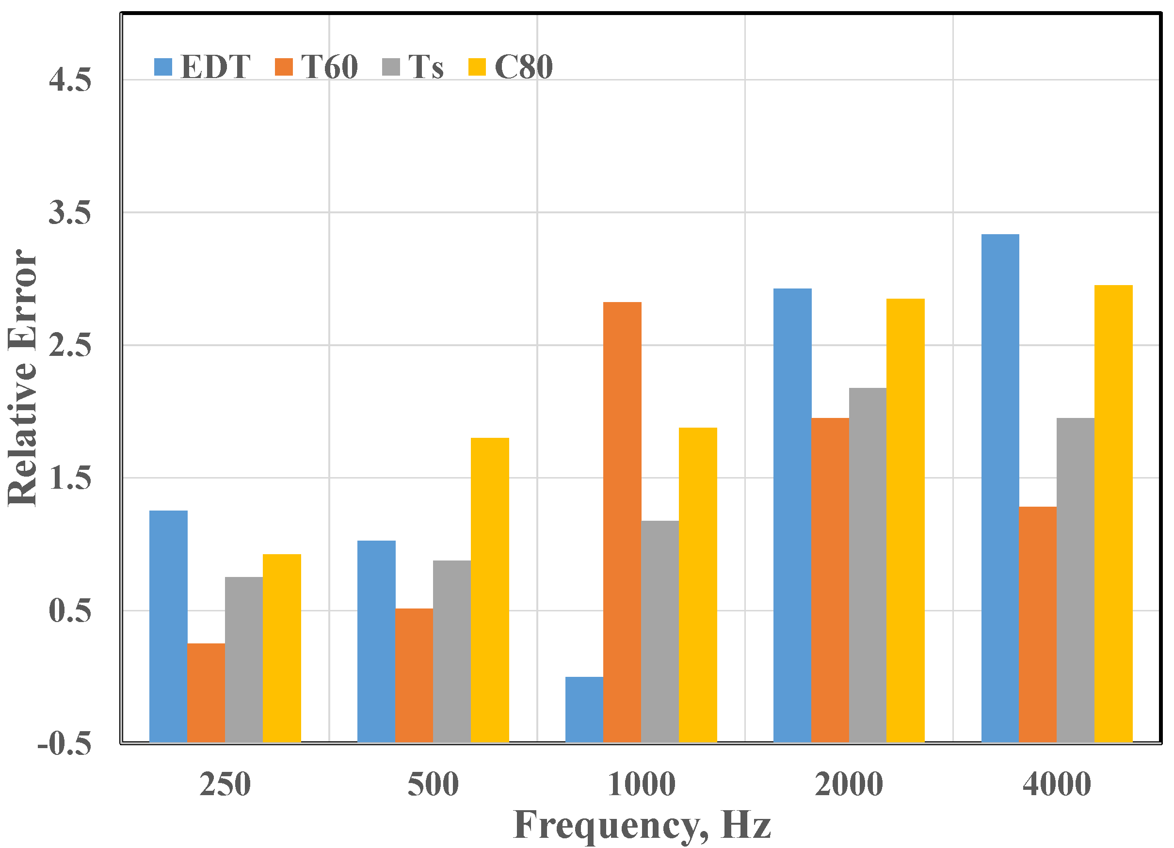
The results of the relative errors for the four acoustical parameters, EDT, T(30), T
s, and C
80 are shown in
Figure 12 below. The results are shown for five frequencies. The relative errors are well below 5.
Reference [
15] presented results for 500 Hz and 2000 Hz also and the relative errors were between 1 and 6. Vorlander [
16] presented results at 1000 Hz in his study and the relative errors ranged between 0.5 and 6.
It is seen therefore the current study results are in the same range as those found in the literature and the simulations are seen to produce realistic results that can be easily incorporated in the design of a music room.
7. Conclusions
The acoustical design of a proposed bar/music venue was compared to actual field measurements. Acoustical separation between the two spaces, ambient sound in the music room and the acoustics of the music room were evaluated through simulation and the results were also determined through field measurements after the facilities were constructed. The results showed that the bar/music venue perform as designed, except for two deficiencies. The deficiencies were appropriately discussed in the current study.
Acknowledgments
The authors would like to thank Jason Stein and Mathew Park of Burdock for giving permission to conduct field measurements as well as assisting during the site measurements. Acknowledgements are due Michelle Martinez, one of our students, in helping to prepare sketches.
Author Contributions
The first author, Ramani Ramakrishnan, contributed to the design specification of the project and evaluated separation details and background noise levels. The second author, Romain Dumoulin, simulated the music room acoustics, design goals and interior room details. The first author modelled the finished facility, conducted site measurements and prepared the manuscript. The second author evaluated the noise reduction data, prepared the subjective limen criteria and the process for calculating the relative errors of the simulation when compared with field data.
Conflicts of Interest
The authors declare no conflict of interest.
References
- Ramakrishnan, R.; Dumoulin, R. Design of a bar/music room—A case study. In Proceedings of the Acoustics Week in Canada, Halifax, 6–9 October 2015.
- ODEON. Simulation Software for Room Acoustics; ODEON: Lyngby, Denmark, 2013. [Google Scholar]
- Vigeant, M.C.; Celmer, R.D.; Jasinski, C.M.; Ahearn, M.J.; Schaeffler, M.J.; Giacomoni, C.B.; Wells, A.P.; Ormsbee, C.I. The effects of different test methods on the just noticeable difference of clarity index for music. J. Acoust. Soc. Am. 2015, 138, 476–491. [Google Scholar] [CrossRef] [PubMed]
- Patania, F.; Gagliano, A.; Galesi, A.; Nocera, F. Proposal to improve the acoustic quality of the main hall of Catania University. In Proceedings of the 16th International Congress on Sound and Vibration 2009, Krakow, Poland, 5–9 July 2009; pp. 1039–1047.
- Orlowski, R. Sound strength and reverberation time in performance and rehearsal spaces for music. In Proceedings of the 2014 Forum Acusticum, Krakow, Poland, 7–12 September 2014.
- Nocera, F.; Gagliano, A.; Evola, G.; Gioia, M.C. Acoustic quality of a tensile membrane structure used as a lecture hall, and proposals for its improvement. Build Acoust. 2014, 21, 287–304. [Google Scholar]
- ISO 3382–1 Acoustics—Measurement of Room Acoustic Parameters—Part 1: Performance Spaces; International Standards Organization: Geneva, Switzerland, 2009.
- ISO 3382–2 Acoustics—Measurement of Room Acoustic Parameters—Part 2: Reverberation Time in Ordinary Rooms; International Standards Organization: Geneva, Switzerland, 2008.
- Beranek, L.L. Concert Halls and Opera Houses—How they Sound; Acoustical Society of America: New York, NY, USA, 1996. [Google Scholar]
- Barron, M. Auditorium Acoustics and Architectural Design; Spon Press: London, UK, 2010. [Google Scholar]
- Rossing, T.D. Acoustics in halls for music and Speech. In Springer Handbook of Acoustics; Springer: Berlin, Germany, 2007. [Google Scholar]
- Dietsch, L.; Kraak, W. Ein Objectives Kriterium zur Erfassung von Echostrorungen bei Musik und Sprachdarbeitungen. Acoustica 1986, 60, 205–216. (In German) [Google Scholar]
- Adelman-Larson, N.W.; Thompson, E.R.; Gade, A.C. Acoustics in rock and pop music halls. In Proceedings of the 122nd Convention of the Audio Engineering Society, Vienna, Austria, 5–8 May 2007.
- Zeng, W.; Christensen, C.L.; Rindel, J.H. Practical methods to define scattering coefficients in a room acoustics computer model. Appl. Acoust. 2006, 67, 771–786. [Google Scholar] [CrossRef]
- Shiokawa, H.; Rindel, J.H. Comparison between Computer Simulations of Room Acoustical Parameters and Those Measured in Concert Hall; Report #89 of the Research Institute of Industrial Technology: Nihon University, Japan, 2007. [Google Scholar]
- Vorlander, M. International round robin on room acoustical computer simulations. In Proceedings of the 15th International Congress on Acoustics, Trondheim, Norway, 26–30 June 1995.
© 2016 by the authors; licensee MDPI, Basel, Switzerland. This article is an open access article distributed under the terms and conditions of the Creative Commons by Attribution (CC-BY) license (http://creativecommons.org/licenses/by/4.0/).


