
Elevating Innovation: Unveiling the Twin Traction Method for a 50-Ton Load Capacity Elevator in Building and Construction Applications
Department of Mechanical Engineering, College of Engineering, Kyung Hee University, 1732 Deogyeong-daero, Giheung-gu, Yongin-si 17104, Gyeonggi-do, Republic of Korea
*
Authors to whom correspondence should be addressed.
Buildings 2024, 14(5), 1244; https://doi.org/10.3390/buildings14051244
Submission received: 4 February 2024
/
Revised: 5 April 2024
/
Accepted: 18 April 2024
/
Published: 27 April 2024
(This article belongs to the Section Construction Management, and Computers & Digitization)
Abstract
:Most commercial elevators for buildings exceeding four stories use a cable-driven traction system. Typically, a single traction machine operates by hoisting the main cable on a traction sheave, thus vertically transporting the elevator car through rotational motion of the sheave. This research introduces a groundbreaking advancement aimed at elevating loading capacity to an unprecedented 50 tons—the highest known in the world. The innovation involves the development of a twin traction system, wherein two traction machines collaborate to lift the elevator. This novel elevator system has demonstrated remarkable capabilities, showcasing the ability to transport up to 300 passengers in a single trip. The installation of this high-capacity elevator system has yielded substantial improvements in construction work efficiency and safety protocols, particularly in scenarios where cranes are traditionally used. The newly developed elevator could lift 50 tons of equipment 60 times a day, whereas the crane was limited to 8 times. The positive impact on labor is also noteworthy, with increased safety and health considerations, especially in adverse weather conditions. By eliminating the need for manual stair climbing, the well-being of the workforce is prioritized. Furthermore, the heightened productivity resulting from a significant reduction in wait times for conventional elevators is a key outcome of this transformative technology. This research not only unveils a groundbreaking twin traction system but also highlights its multifaceted features in enhancing efficiency, safety, and overall productivity in various industries.
1. Introduction
Accidents resulting in fatalities have long been a critical concern in construction projects requiring the lifting of super-heavy objects to elevated sites, such as high-rise building construction sites [1,2]. In these dynamic work environments, where thousands to tens of thousands of workers need vertical transportation means, there arises a vital demand for large cargo elevators that not only prioritize safety but also exhibit high transport efficiency, surpassing the limitations of conventional small passenger lifts and cranes for heavy lifting [3,4,5].
Traditionally, the heaviest large structures lifted using cranes weigh approximately 50 tons [6]. Large construction sites often host labor forces exceeding a thousand workers who traverse significant heights multiple times a day [7]. While tower cranes, hydro cranes, crawler cranes, and winches are common tools for lifting heavy objects, their operational speed is notably slow, impeding night-time and adverse weather operations, where the risk of accidents is heightened [8,9]. Safety concerns further restrict other work within the crane’s working radius, diminishing overall work efficiency [10,11]. The prevalent use of stairs or small lifts (typically accommodating 20 people for a 3-ton class) results in prolonged waiting times for vertical transportation, contributing to low productivity and economic waste [7]. Therefore, there is an imperative need to develop and implement substantial lifts capable of safely transporting high-load cargo and large numbers of people, even in challenging weather conditions and during night-time operations. While studies on elevators for cargo and emergency rescue have been published [12,13,14], to the best of the author’s knowledge, there has been no elevator designed to carry cargo with a maximum load of 50 tons, which can accommodate hundreds of people on a single trip [13,14,15,16].
Despite advancements in technology leading to the construction of super-high-rise buildings and large-scale multi-use facilities, elevating measures for lifting super-large and heavy loads and transporting thousands of people have not kept pace with construction history [8,17]. The conventional method of using cranes for large-scale loads carries inherent risks due to the direct suspension of heavy objects in open spaces [18]. Current elevators for construction sites, typically designed for loads of 3 tons of cargo or 20 passengers, often necessitate coupling with stair walking, leading to inefficiencies in construction projects [7,8].
Elevators with a capacity of 50 tons provide a safer and more efficient alternative, which is in line with modern industry standards where safety is of utmost importance [19,20]. In total, 50 tons can transport up to 300 passengers on a single trip. Our developed system, known as the twin traction elevator (TTE) method in this study, is a twin traction inverter vector drive rope-type elevator [21]. Given the critical nature of elevator reliability, particularly in preventing fatalities, elevator technology prioritizes maximizing reliability over pushing the boundaries of performance. Incorporating multiple redundancies for safety and ensuring operability in harsh weather conditions are the essential aspects of elevator engineering.
This article commences with an introduction to the proprietary twin traction drive and roping design followed by more safety features of the elevator system. The article will continue with a presentation of the performance test results, a detailed account of the actual installation outcomes, and conclude with insights and potential applications.
2. Twin Traction Drive and Roping Design
Traditional rope elevators designed for buildings exceeding four stories typically rely on a single traction drive system. However, ensuring the secure transportation of a 50-ton load and/or accommodating hundreds of people necessitates a single drive system of considerable size. This poses a significant challenge in terms of the on-site installation feasibility [22]. Additionally, the demand for at least four critical bending points (assuming 8:1 roping) increases roping fatigue, leading to frequent maintenance requirements. The absence of redundancy in this configuration also introduces safety concerns in and of itself.
As of the writing of this article, the authors are unaware of any reported instances of operational single-drive systems capable of reliably and safely transporting a 50-ton load. In response to the limitations of a single-drive system the TTE system has been developed. The TTE system incorporates two traction devices, inherently possessing redundancy characteristics. The analogy here is akin to an airplane engine. Just as multiple engines can generate more lift while minimizing weight, the incorporation of the additional engines offers inherent redundancy, thereby enhancing safety measures.
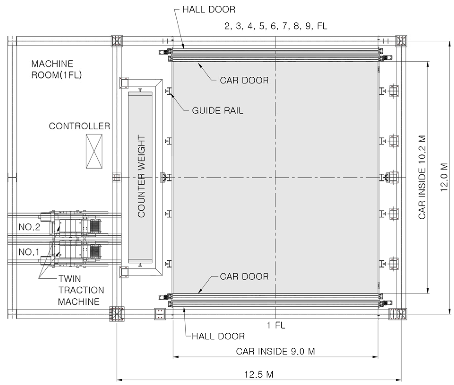
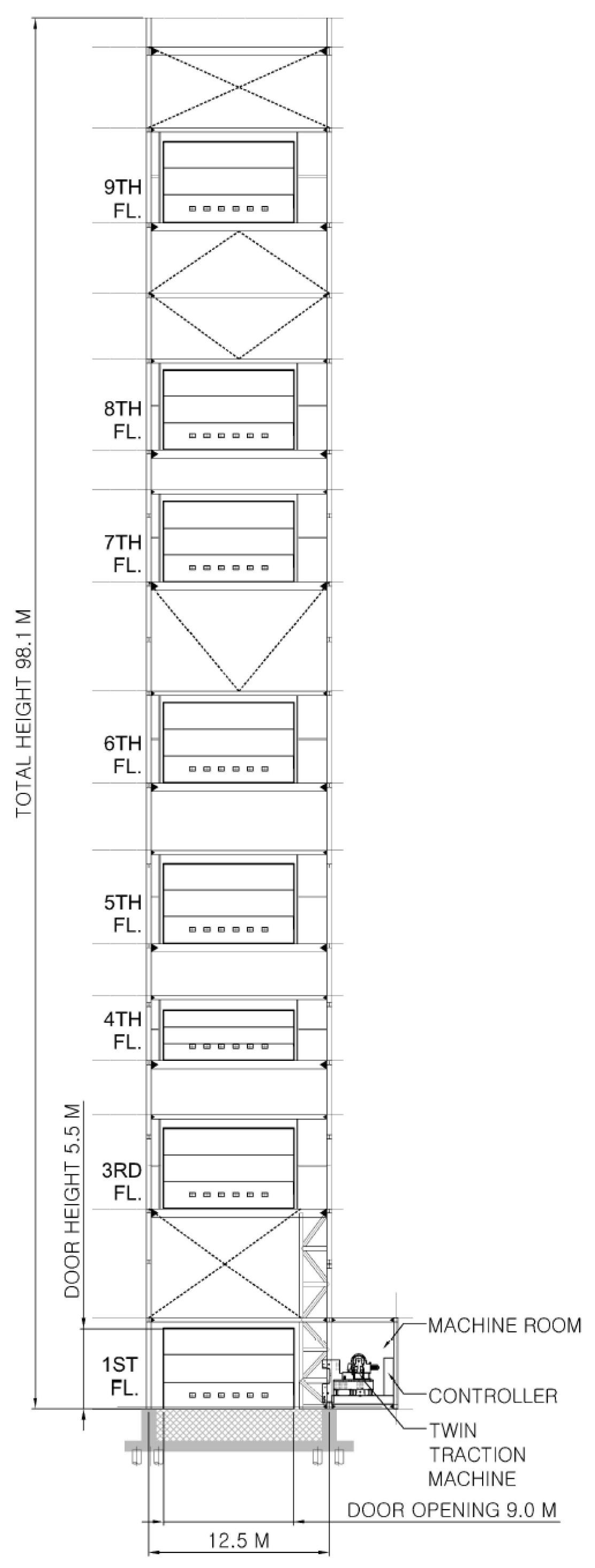
The plan view of the TTE system is in Figure 1, and the elevation view of an installed example is in Figure 2. The cross-section of the boarding car counterweight wire rope and the platform door of the steel frame structure can be seen in the two figures. The inside dimensions of the boarding car are 9.0 m × 10.2 m, and it is 5.5 m in height. The spacious car is to load not only heavy, but also large loads such as machinery and materials.
2.1. Twin Traction Drive Design
The traction drive comprises four primary components, as depicted in Figure 3. Power is transmitted through a three-phase induction motor, which then engages with the worm and worm gear. This interaction induces the rotation of the traction sheave, gripping the rope. A strategically positioned brake is interposed between the motor and the worm for operational control [23].
In accordance with textbook references [3], the capacity (Q) of a traction drive can be determined using Equation (1). In this calculation, the roping velocity (V) is established at 30 m/min, and the counterweight–payload ratio (B) is set at 0.5, ensuring equilibrium when 50% of the payload (L) is loaded onto the car. The payload itself is specified as 50,000 kg (50 tons), and the efficiency (η) of the worm reducer is assigned as 0.65. Subsequently, the computed capacity is found to be 189 kW.
In this study, taking into account the friction loss and starting torque associated with the guide rail rope sheave, we opted for the application of two units of 110 kW each. This decision involves integrating the concept of distributed processing systems, widely employed in recent computer CPU designs and various machine applications, into the design of the traction drives [22]. The objective is to facilitate automatic load distribution and improve the scalability of the equipment.
2.2. Roping Design of TTE
The hoisting mechanism and the driving motor were carefully configured as twins (Figure 4), and the traction wire rope suspended the super-large boarding car, maintaining equilibrium at eight points. The primary objective was to establish a tilting safety device capable of detecting and signaling eccentric loads when loading super-large, heavy loads, and accommodating hundreds of people on board. The Z-shaped roping and the ABBA-sequenced roping methods have both been patented [21,24]. There is only one critical 90 degree bending point (marked with dashed circle in Figure 4) and seven normal bending points for each rope (Figure 5), which reduces rope fatigue compared with projected single traction device designs. As previously stated, a conventional single traction system that typically uses 8:1 roping will have four critical bending points, which are the primary points of observation during maintenance. The TTE system will also halve the overall load on a single rope, so the fatigue on a critical bending point will decrease at least by 1/8, thus reducing necessary repair requirements [25].
In adherence to the Korean Elevator Safety Management Act, a minimum safety ratio (Sr) of 12 is mandated. The calculation of Sr, as per Equation (2), involves inserting values for the load (L), empty car mass (P) in kg, roping number (k), the number of ropes (N), the unit mass of rope (Wr) in kg/m, travel distance (H) in meters, and breaking load (Pr) in kgf. For our system, utilizing 36 strands of 16 mm diameter with a 4:1 roping application, the values applied are 50,000, 45,000, 4, 36, 0.878, 32, and 13,704, respectively. This configuration resulted in a safety factor of 19.9, significantly surpassing the safety requirements. Notably, the TTE employs the same roping features for both traction machines for redundancy, ensuring the secure raising and lowering of the 50-ton loads.
3. Safety Features
The system also features a load cell display monitor, brake fall safety device, and an all-weather operation system for conditions such as rain, wind, snow, and icing [26].
3.1. Safety Device Design
When loading high-capacity equipment and cargo weighing 50 tons into an elevator car, there is a risk of significant accidents and hazardous situations if the mass surpasses the designated load limit. To mitigate this risk, a monitoring device, as illustrated in Figure 6, is implemented to verify the actual loading conditions [27,28]. A tilting sensor to detect eccentric loads and anti-creeping device is also installed [29,30].
In Figure 7, an additional wire rope emergency stop brake is depicted, installed independently from the multiple safety devices attached to the car. This feature serves to prevent falls and unexpected acceleration, ensuring a secure stop even in unforeseen and dangerous situations [31].
Moving on to Figure 8, a device capable of detecting wind speed beyond a pre-set threshold value is presented. Equipped with an anemometer positioned at the top, this device triggers an alarm, flashes an alert on the monitor, and simultaneously evacuates the elevator car to the lowest floor in the event of high wind speeds [32,33].
Figure 9 showcases an overspeed safety device designed to forcibly bring the elevator to a halt. If a mechanical or electrical anomaly occurs in the hoisting machine, control system, or towing rope, or if the boarding car descends at a speed exceeding the prescribed rate, the power is cut off, and the brakes are activated. Simultaneously, the emergency stop device installed in the boarding car engages, guiding the car to the guide rail.
Figure 10 illustrates the integration of the aforementioned four safety features. This strategic application of redundancy is equivalent to safety design methods commonly found in aircraft, and we refer to this comprehensive approach as the Load cell–Rope brake–Overspeed governor–Wind Speed Meter and Control (LROW) method.
3.2. Steel Structure Design of Hositway
The hoistway of the 50-ton load elevator was designed with a steel beam structure. The importance factor (Iw) is 1.0, wind speed plus factor (Kzt) is 1.0, the maximum height of the structure is 111.5 m, the altitude distribution coefficient of wind speed (Kzx) is 1.269 m/s, and the design wind speed (Vz) is 31.725 m/s. Therefore, according to Equation (3) [3], the design velocity pressure was calculated as 613.95 N/m2.
The structural analysis of the steel structure hoistway was performed using the Midas Gen program. Figure 11 is the result of a 3D structural analysis of the steel structure hoistway and Figure 12 is a steel rib plate moment diagram from −20.80 N·m/m marked in red to 8.93 N·m/m marked in blue, and Table 1 shows the moment value.
4. Results from Performance Test
In this study, safety and practical performance were verified through the performance tests of the newly developed twin traction elevator system. The tests were conducted by the Korea Industrial Safety Association (KISA), which is the national safety agency, using dedicated test facilities following the Korean Framework Act on Industrial Safety. Among the test criteria were load tests, brake performance, and landing errors.
4.1. Load Test and Implantation Precision Measurement
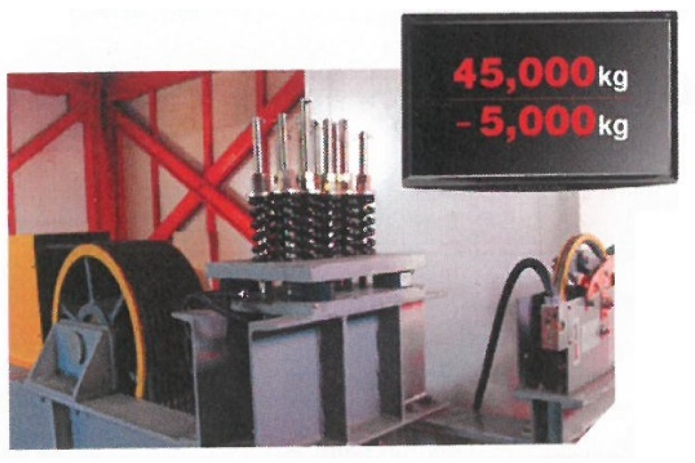
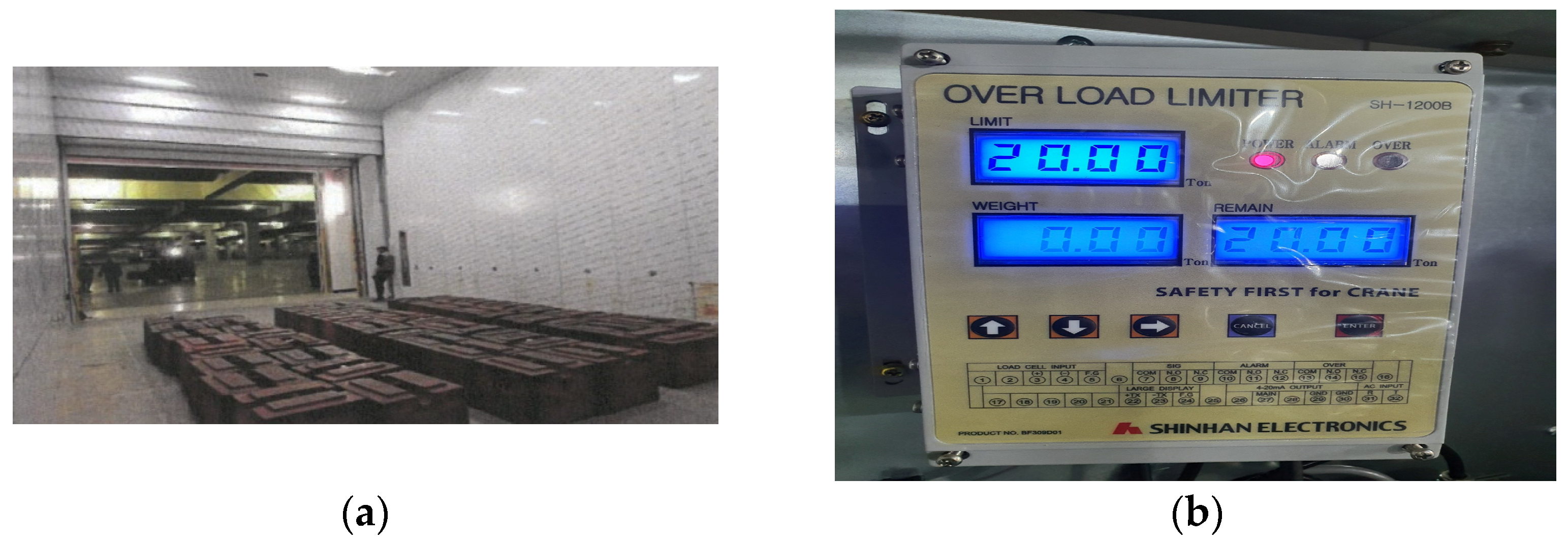
A total of 50 single-ton weight pallets were loaded inside the elevator car, and tests were conducted by raising and lowering the elevator car from the lowest floor to the top floor at a height of 82.85 m. The test showed no problems. Furthermore, when five more single-ton pallets were added to the 50 tons, the elevator operation was stopped and the alarm was sounded in line with the overload prevention safety measure. Figure 13 is a photo confirming that the overload prevention device set for load testing and the 50-ton loading capacity works.
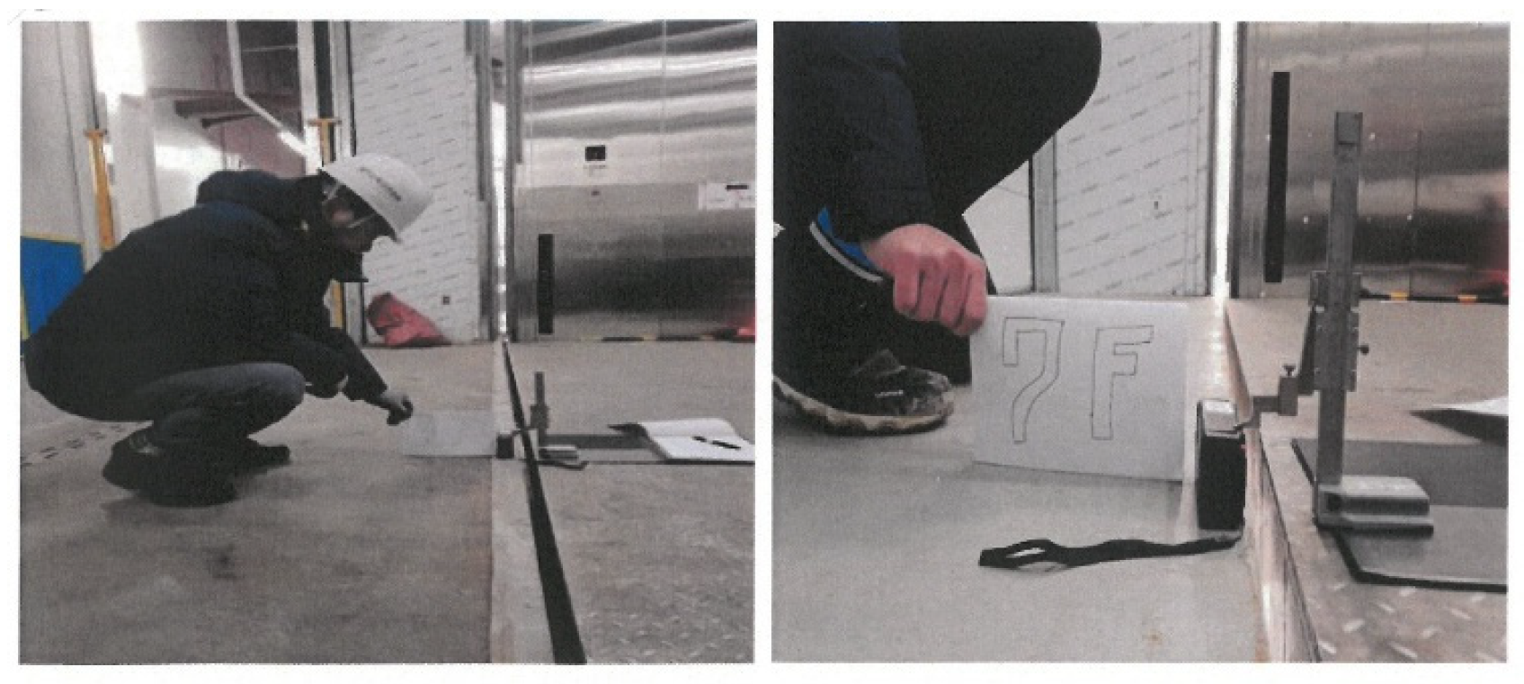
Five tests on the landing error of each floor of the boarding car when lifting and descending with a 50-ton load were conducted and the results are shown in Table 2. The average value was 1.12 mm, indicating that the landing performance is much better than the standard value of 10.0 mm. Figure 14 is a picture of the landing error measurements.
4.2. Measurement of Brake Insulation Resistance and Residual Voltage
In the test of the main brake for the LROW method, when the brake is opened and operated, the standard for the gap between the magnetic plunger that opens the brake must be 3.5 mm or less to reduce the idle distance and exert rapid braking power. Five measurements were taken and Table 3 shows the results.
The insulation resistance for the 110 kW 50-ton main motor three-phase power supply (440 V 60 Hz) was 999.9 MΩ, and there was no abnormality in the withstand voltage and residual voltage tests.
4.3. Comparison with Crane
Traditionally, when 50 tons of cargo needs to be lifted, a crane was used. However, crane lifting is greatly limited by daylight usage and by weather conditions such as rain, wind, and snow; furthermore, there is always a risk of the payload falling, and deficiencies due to other structures or circumstances limiting operation within a certain working radius, which drastically decreases work efficiency.
Table 4 compares the transport capability of the newly developed 50-ton twin traction elevator and a crane by measuring the time taken to lift 50 tons from a real-world work site. The elevator could lift 50 tons of equipment safely more than 60 times a day, whereas the crane was limited to a maximum of 8 times. This means that the efficiency of lifting heavy loads of the TTE method was better by a factor of 7.5. Figure 15 is a picture of the 50-ton loading on the new elevator and crane. Additionally, the need for a support staff to operate the crane presents a disadvantage, as it diminishes the efficient utilization of the labor force.
4.4. Industrial Site Installation
Figure 16 depicts the configuration diagram of the 50-ton twin traction elevator developed in this study. The system encompasses key components such as the twin traction machine situated in the top machine room, the boarding car, counterweight, wire rope, heavy-load guide rail, platform safety door, boarding car safety door, wind speed control safety device, loading weight measuring device, car tilting sensor, rope brake, overspeed governor, shock absorber, CCTV camera, emergency lighting device, control panel, and driving device.
This 50-ton elevator has been successfully installed and put into operation at nine sites worldwide as of the writing of this article. The highest distance is 110 m and the deepest underground is 500 m. The actual photos of the sites at Samsung Display and LG Display are in Figure 17a and Figure 17b, respectively. It has been instrumental in transporting 50-ton high-load equipment and materials, allowing approximately 300 individuals to board and operate it simultaneously, in line with its design specifications. Notably, the previous 3-ton, 20-seater small lift was found to be inadequate, accommodating only 15 people. Therefore, it became evident that the transportation efficiency of this 50-ton large lift surpassed the smaller alternative by over 20 times. Moreover, the ride comfort and passenger satisfaction levels significantly outperformed the existing rack and pinion-driven small lift, which experienced notable issues with noise and vibration.
The favorable response from the labor force was reassuring, particularly in light of the correlation between fatigue and reaction times. Research indicates that climbing stairs induces fatigue, which in turn prolongs reaction times [34,35]. In the context of construction sites, swift reaction times can be critical, often delineating the line between safety and peril. Consequently, workers would often find themselves compromised in situations where they were operating below optimal performance levels simply to reach their designated work areas. The introduction of this elevator system has alleviated many aspects of this concern.
5. Conclusions
In this research endeavor, we successfully developed a 50-ton capacity large heavy-load elevator (named Goliath Elevator), subjecting it to thorough analysis, verification, and certification by the Korea Industry Safety Association (2018-2033608). The significance of this elevator lies in its pivotal role in safely, efficiently, and economically lifting heavy loads while vertically transporting large groups of people. The comprehensive evaluation demonstrated a remarkable improvement in safety performance and transportation efficiency, showcasing exceptional precision in landing and notable results in loading and unloading tests when compared to conventional cranes. This affirms the effectiveness of the twin traction method proposed in this study. Moreover, the Goliath Elevator system earned the prestigious Korean World-class Product Award in 2019.
The limitations of this system primarily manifest during the installation phase. Setting up the elevator system necessitates the temporary use of a crane, requiring adequate space for its operation. Additionally, excavation of a pit beneath the intended elevator location is mandatory. Establishing a robust foundation for the pit is crucial, often requiring additional piles to be driven based on soil conditions. In locations with challenging terrain, such as marine environments where pit construction is impractical, alternative access methods like ramps for forklifts or staircases are employed.
The envisaged applications for this technology span super-large offshore plants, semiconductor display production facilities, underground high-speed railway stations, radioactive waste storage sites, and high-rise building construction sites. Looking ahead, our future plans involve the development of an 80-ton capacity elevator, capable of transporting 500 people at once. Moreover, we are dedicated to developing an elevator specifically tailored for shipping containers. This innovation is aimed at ports where numerous shipping containers are often left exposed outdoors, with the aim of streamlining operations in fulfillment centers. Additionally, our research targets the development of multicage and double-deck elevators to address evolving industry needs.
Author Contributions
Conceptualization, G.-Y.K. and S.-H.J.; methodology, G.-Y.K.; software, G.-Y.K.; validation, G.-Y.K. and S.-H.J.; writing—original draft preparation, G.-Y.K.; writing—review and editing, S.-H.J. All authors have read and agreed to the published version of the manuscript.
Funding
This research received no external funding.
Data Availability Statement
The original contributions presented in the study are included in the article, further inquiries can be directed to the corresponding authors.
Conflicts of Interest
The authors declare no conflicts of interest.
References
- Arifuddin, R.; Latief, R.U.; Suraji, A. An investigation of fall accident in a high-rise building project. IOP Conf. Ser. Earth Environ. Sci. 2020, 419, 012144. [Google Scholar] [CrossRef]
- Santo, D.; Balthazar, J.; Tusset, A.; Piccirilo, V.; Brasil, R.; Silveira, M. On nonlinear horizontal dynamics and vibrations control for high-speed elevators. J. Vibrat. Control 2018, 24, 825–838. [Google Scholar] [CrossRef]
- Strakosch, G.R. Vertical Transportation: Elevators and Escalators; Wiley: Hoboken, NJ, USA, 1967. [Google Scholar]
- Zarikas, V.; Papanikolaou, N.; Loupis, M.; Spyropoulos, N. Intelligent decisions modeling for energy saving in lifts: An application for kleemann hellas elevators. Energy Power Eng. 2013, 5, 236–244. [Google Scholar] [CrossRef]
- Wang, J.; Pi, Y.; Krstic, M. Balancing and suppression of oscillations of tension and cage in dual-cable mining elevators. Autom 2018, 98, 223–238. [Google Scholar] [CrossRef]
- Mohaney, S.; Shah, M. Emerging trends in vertical elevating system. Int. J. Eng. Manag. Res. 2015, 5, 51–56. [Google Scholar]
- Ishii, T. Elevators for skyscrapers. IEEES 1994, 31, 42–46. [Google Scholar] [CrossRef]
- Al-Kodmany, K. Tall buildings and elevators: A review of recent technological advances. Buildings 2015, 5, 1070–1104. [Google Scholar] [CrossRef]
- Cao, G.; Wang, N.; Wang, L.; Zhu, Z. Nonlinear dynamic response of cable-suspended systems under swinging and heaving motion. J. Mech. Sci. Technol. 2017, 31, 3157–3170. [Google Scholar] [CrossRef]
- Andrew, J.; Kaczmarczyk, S. Systems Engineering of Elevators; Elevator World: Mobile, AL, USA, 2011. [Google Scholar]
- Bao, J.-H.; Zhang, P.; Zhu, C.-M.; Sun, W. Transverse vibration of flexible hoisting rope with time-varying length. J. Mech. Sci. Technol. 2014, 28, 457–466. [Google Scholar] [CrossRef]
- Kim, G.-Y.; Jang, S.-H. A study on an emergency evacuation elevator equipped with a three hour fireproof door for high-rise buildings, facilities for the handicapped, medical facilities and multiuse facilities. J. Korean Soc. Manuf. Technol. 2022, 31, 12–18. [Google Scholar]
- Siikonen, M.-L. Planning and Control Models for Elevators in High-Rise Buildings; Helsinki University of Technology, KONE Corporation: Espoo, Finland, 1997. [Google Scholar]
- Barney, G. Vertical transportation in tall buildings. Elev. World 2003, 51, 66–75. [Google Scholar]
- Nijdam, E.M. Elevator Model. Design of an Elevator Model for Teaching in the Field of Automation. Master’s Thesis, The Arctic University of Norway, UiT, Tromsø, Norway, 2019. [Google Scholar]
- Kim, G.-Y. Super Sized Elevator for Manufacturing Large Vessel and Ocean Plant Equipment. KR101556911B1, 2 October 2015. [Google Scholar]
- Janovský, L. Elevator Mechanical Design; Elevator World Inc.: Mobile, AL, USA, 1999. [Google Scholar]
- Chambers, H. Heavy-load moving systems. Mar. Technol. SNAME News 1976, 13, 192–198. [Google Scholar] [CrossRef]
- Li, K.; Mannan, M.; Xu, M.; Xiao, Z. Electro-hydraulic proportional control of twin-cylinder hydraulic elevators. Control Eng. Pract. 2001, 9, 367–373. [Google Scholar] [CrossRef]
- Niu, D.; Guo, L.; Zhao, W.; Li, H. Operation performance evaluation of elevators based on condition monitoring and combination weighting method. Measurement 2022, 194, 111091. [Google Scholar] [CrossRef]
- Kim, G.-Y. Super Size Rope Type Elevator for Extremely Heavy Load Drived by Twin Traction Machine. KR101887613B1, 10 August 2018. [Google Scholar]
- Matsukura, Y.; Honda, T.; Niikawa, M.; Okada, K.; Enomoto, J.; Suzuki, K. Traction Technology for Elevators. In Elevator Technology 2; 1988; pp. 163–172. Available online: https://www.google.com/search?q=Elevator+Technology&oq=Elevator+Technology&gs_lcrp=EgZjaHJvbWUyBggAEEUYOTIGCAEQRRg90gEHMzk5ajBqNKgCALACAQ&sourceid=chrome&ie=UTF-8 (accessed on 17 April 2024).
- Li, D.; Yang, J.; Liu, Y. Research on state recognition technology of elevator traction machine based on modulation feature extraction. Sensors 2022, 22, 9247. [Google Scholar] [CrossRef] [PubMed]
- Kim, G.-Y. Roping Method to Improve Traction Stability and Rope Life of Super Size Elevator for Extremely Heavy Load. KR101877955B1, 12 July 2018. [Google Scholar]
- Awatramani, J.; Verma, G.; Hasteer, N.; Sindhwani, R. Investigating Strategies and Parameters to Predict Maintenance of an Elevator System; Springer: Singapore, 2022; pp. 323–332. [Google Scholar]
- Roberts, R. Control of high-rise/high-speed elevators. In Proceedings of the 1998 American Control Conference, Philadelphia, PA, USA, 24–26 June 1998; IEEE: Piscataway, NJ, USA, 1998; pp. 3440–3444. [Google Scholar]
- Kim, W.-Y. Device for Indicating Loading Weight of Elevator. KR100621457B1, 19 September 2006. [Google Scholar]
- Kim, G.-Y.; Kim, H. Weight Capacity Detection Apparatus of Elevator Car and Detection Method Capable of Preventing Overload Determination Error. KR102301043B1, 10 October 2021. [Google Scholar]
- Kim, G.-Y. Safety Apparatus for Preventing Car Tilt Accident of Freight Elevator and Service Elevator. KR102144642B1, 13 October 2020. [Google Scholar]
- Kim, G.-Y. Anti-Creeping Device of Freight Elevator and Super-Sized Elevator. KR102182983B1, 25 November 2020. [Google Scholar]
- Feng, S.; Chen, J.; Liang, Y.; Ju, Y. Research on Car Locking Device to Prevent the Car from Moving Accidentally; Springer Nature: Singapore, 2022; pp. 265–270. [Google Scholar]
- Kim, G.-Y. Weather Proof Outdoor Lift for Person and Freight Having Wind Protector of Cable. KR102023060B1, 4 November 2019. [Google Scholar]
- Kim, G.-Y. Super Sized Elevator Having Wind Protector of Cable for Manufacturing Large Vessel and Ocean Plant Equipment. KR101632385B1, 21 June 2016. [Google Scholar]
- Tavahomi, M.; Shanbehzadeh, S.; Abdollahi, I. Comparing the effect of fatigue on choice reaction time of healthy men and women. PTJ 2017, 7, 29–34. [Google Scholar] [CrossRef]
- Huang, Q.; Maruyama, H.; Huo, M. Probe reaction time changes with fatigue induced by climbing up- and -down stairs. J. Phys. Ther. Sci. 2012, 24, 995–997. [Google Scholar] [CrossRef]
Figure 1.
Drawing of 50-ton elevator plan (not to scale).

Figure 2.
Drawing of 50-ton elevator elevation (not to scale).

Figure 3.
Illustration of twin traction drives, where each component is colored and labeled on one side.
Figure 3.
Illustration of twin traction drives, where each component is colored and labeled on one side.

Figure 4.
Wire roping diagram on car (top view) Rope A (black) and Rope B (blue). Dashed circles are critical bending points.
Figure 4.
Wire roping diagram on car (top view) Rope A (black) and Rope B (blue). Dashed circles are critical bending points.

Figure 5.
Wire roping diagram (planar view of Figure 4).
Figure 5.
Wire roping diagram (planar view of Figure 4).

Figure 6.
A 50-ton load cell and display monitor.

Figure 7.
50-ton rope brake device.

Figure 8.
Wind Speed Meter and Control device manufactured by Yuyu Instrument, Seoul Korea.

Figure 9.
Overspeed governor machine.

Figure 10.
Block diagram of the safety device system.

Figure 11.
Result of structural analysis.

Figure 12.
Moment analysis of rib plate.

Figure 13.
A50-ton load test. (a) A total of 50 single ton pallets loaded; (b) overload limiter.

Figure 14.
Landing tolerance measurement.

Figure 15.
The 50-ton elevator and crane lifting. (a) Elevator loading; (b) crane lifting.

Figure 16.
Heavy-duty 50-ton capacity passenger and freight twin traction elevator.

Figure 17.
Installed 50-ton capacity heavy-duty passenger and freight twin traction elevator (a) Samsung Display; (b) LG Display.
Figure 17.
Installed 50-ton capacity heavy-duty passenger and freight twin traction elevator (a) Samsung Display; (b) LG Display.


Table 1.
Moment of rib plate.
| σmax | σmin | ø | Fn | σmax/øFn |
|---|---|---|---|---|
| 8.848 MPa | 8.848 MPa | 0.650 | 51.00 MPa | 0.267 |
Table 2.
Result of car landing tolerance test.
| Floor | Measurements (mm) | Avg. | ||||
|---|---|---|---|---|---|---|
| #1 | #2 | #3 | #4 | #5 | ||
| 7F | 1.82 | −0.82 | −0.14 | 1.52 | 1.76 | 0.828 |
| 6F | 2.54 | 2.62 | −0.34 | 2.32 | 2.34 | 1.896 |
| 5F | 2.35 | 2.64 | 2.42 | 2.12 | 2.02 | 2.31 |
| 4F | 1.53 | 1.12 | 1.44 | 1.32 | 1.25 | 1.332 |
| 3F | 2.23 | 1.05 | −2.10 | −0.25 | −0.57 | 0.072 |
| 2F | 2.14 | −1.32 | 1.02 | −1.35 | 2.53 | 0.604 |
| 1F | 1.82 | −0.82 | −0.14 | 1.52 | 1.76 | 0.828 |
| Avg. | 2.06 | 0.64 | 0.31 | 1.03 | 1.58 | 1.12 |
Table 3.
Gap of brake magnetic plunger.
| Lining Thickness (mm) | Brake Gap (mm) | Plunger Movement (mm) | ||||
|---|---|---|---|---|---|---|
| Measurement | Avg | Measurement | Avg | |||
| No. 1 (K3) | Left | 9.89 | 10.01 | 0.12 | 2.05 | 2.05 |
| 9.91 | ||||||
| 10.12 | 2.05 | |||||
| 10.08 | ||||||
| 10.07 | 2.05 | |||||
| Right | 10.59 | 10.28 | ||||
| 10.52 | 2.04 | |||||
| 10.41 | ||||||
| 9.98 | 2.05 | |||||
| 9.98 | ||||||
| No. 2 (K4) | Left | 9.88 | 10.02 | 0.12 | 2.04 | 2.04 |
| 9.98 | ||||||
| 9.84 | 2.05 | |||||
| 10.2 | ||||||
| 10.2 | 2.05 | |||||
| Right | 10.3 | 10.27 | ||||
| 10.78 | 2.05 | |||||
| 10.11 | ||||||
| 10.13 | 2.05 | |||||
| 10.01 | ||||||
Table 4.
Comparison of newly developed 50-ton elevator vs. conventional crane lifting.
| Height 82.85 m | Elevator | Crane |
|---|---|---|
| Preparation Works | 0 | 3 h |
| Safety Barrier | 0 | 2 h |
| Cyclic Loading | 5 min | 30 min |
| Cyclic Lifting | 5 min | 15 min |
| Cyclic Unloading | 5 min | 30 min |
| Cyclic Activity Total * | 15 min | 75 min |
| Workable Hours/day | 15 | 10 ** |
| Number of Lifts/day | 60 times/15 h | 8 times/10 h |
| Safety Assistance | none | at least 6 people |
* Cyclic Activity Total = Cyclic Loading + Cyclic Lifting + Cyclic Unloading. ** daytime, weather permitting.
Disclaimer/Publisher’s Note: The statements, opinions and data contained in all publications are solely those of the individual author(s) and contributor(s) and not of MDPI and/or the editor(s). MDPI and/or the editor(s) disclaim responsibility for any injury to people or property resulting from any ideas, methods, instructions or products referred to in the content. |
© 2024 by the authors. Licensee MDPI, Basel, Switzerland. This article is an open access article distributed under the terms and conditions of the Creative Commons Attribution (CC BY) license (https://creativecommons.org/licenses/by/4.0/).
Share and Cite
MDPI and ACS Style
Kim, G.-Y.; Jang, S.-H. Elevating Innovation: Unveiling the Twin Traction Method for a 50-Ton Load Capacity Elevator in Building and Construction Applications. Buildings 2024, 14, 1244. https://doi.org/10.3390/buildings14051244
AMA Style
Kim G-Y, Jang S-H. Elevating Innovation: Unveiling the Twin Traction Method for a 50-Ton Load Capacity Elevator in Building and Construction Applications. Buildings. 2024; 14(5):1244. https://doi.org/10.3390/buildings14051244
Chicago/Turabian StyleKim, Gi-Young, and Seung-Ho Jang. 2024. "Elevating Innovation: Unveiling the Twin Traction Method for a 50-Ton Load Capacity Elevator in Building and Construction Applications" Buildings 14, no. 5: 1244. https://doi.org/10.3390/buildings14051244
Note that from the first issue of 2016, this journal uses article numbers instead of page numbers. See further details here.