
Environmental Impact on the Behavior of CFRP Sheet Attached to Concrete


1
Structural Designer, Infrastructure Consulting & Engineering, Raleigh, NC 27609, USA
2
Department of Engineering and Technology, Texas A&M University-Commerce, Commerce, TX 75429, USA
3
Lyles School of Civil Engineering, Purdue University, West Lafayette, IN 47907, USA
4
Department of Civil and Environmental Engineering, University of Missouri, Columbia, MO 65211, USA
*
Author to whom correspondence should be addressed.
Buildings 2022, 12(7), 873; https://doi.org/10.3390/buildings12070873
Submission received: 2 June 2022
/
Revised: 20 June 2022
/
Accepted: 20 June 2022
/
Published: 21 June 2022
(This article belongs to the Collection Advanced Concrete Materials in Construction)
Abstract
:Carbon fiber-reinforced polymer (CFRP) has many advantages as a construction/structural-strengthening material. However, there are still concerns regarding the long-term performance of these materials when used with reinforced concrete (RC) structures. Environmental conditions have an adverse effect on the behavior of CFRP and the bond between these sheets and concrete. Therefore, the durability of CFRP used for strengthening RC beams was evaluated under different environmental scenarios, including subjection to immersion in deicing agents, tap water, and saltwater, freeze-and-thaw cycles, and outdoor environmental changes. Laboratory tests were performed to examine the influence of these environmental scenarios on the bonding behavior between CFRP sheets and concrete in terms of deformations and modes of failure. Two types of test setups were performed in this study, namely pull-off shearing and three-point bending. Forty-two concrete prisms with CFRP were prepared and tested by using the pull-off shearing setup. It was observed that as the period of exposure increased, noticeable effects on the CFRP sheet as well as the bond stiffness were observed. Exposure to tap water had a greater impact than saltwater on the CFRP–concrete bond strength as well as the CFRP. In addition, eighteen notched concrete beams strengthened with an external CFRP were tested under three-point bending. The tap water exposure showed a 3.6% increase in the bond strength compared to the control specimen. However, the saltwater exposure showed a 10% increase.
1. Introduction
Strengthening RC beams or columns by composite material has lots of advantages. The low density, high specific strength, corrosion resistance, and ease of installation make fiber-reinforced polymers (FRPs) a suitable technology for strengthening or rehabilitating structures. Until now, their cost and long-term behavior make their development doubtable. Enormous costs associated with synthetic FRPs may limit their use in several low-budget applications [1,2]. Low-cost and easily available fiber rope-reinforced polymer composites were used to strengthen concrete columns [1]. Moreover, low-cost glass fiber sheets were used to upgrade concrete with waste aggregate [2]. Carbon fiber-reinforced polymer (CFRP) has superior mechanical properties and higher tensile strength, stiffness, and durability compared with other fiber-based systems. Therefore, CFRP was the strengthening technique in this study. The bond strength between CFRP and concrete is the main factor for controlling failures of strengthened structures [3]. The rough surface of CFRP showed superior bond strength when compared to the smooth surface of CFRP [4]. The geometry, in terms of length and width, of CFRP is a major factor that shapes the bond strength [5]. The durability of CFRP materials in different environments is one of the primary issues that has limited the development of these materials in the application of some infrastructure [6]. The CFRP materials are usually very sensitive to different environmental conditions, mostly moisture and temperature [7]. With regard to application, it is crucial for a designer to consider not only the short-term characteristics of the materials but also the rates of deterioration of FRP composites as a function of exposure condition and time [8].
Previous studies examined the effect of exposure to different environmental conditions on the fabric attached to concrete using an epoxy adhesive or cement-based adhesive [8,9,10,11,12]. The degradation of the bond between the CFRP and concrete was attributed to the deterioration of the concrete surface [9]. The effect of extreme temperature (over 200 °C) on concrete prisms with attached CFRP using epoxy adhesive was investigated. The epoxy adhesive bond strength decreased gradually as the temperature increased [10]. The thermal cycles in the air increased the interfacial fracture energy of the CFRP–concrete whereas the interfacial fracture energy was reduced due to the thermal cycles in water. Thermal cycles in water caused the failure mode to change from concrete cohesive failure to primer–concrete interfacial debonding [11]. The bond behavior of the FRP–concrete interface under a hygrothermal environment was studied [12]. The ultimate bearing capacity of the interface was reduced by up to 27.9% after exposure to the hygrothermal environments (high temperature and humidity).
Atadero et al. [13] tested cracked concrete beams that were repaired by using CFRP after being exposed to environmental conditions such as moisture, chloride deicer, non-chloride deicer, and freeze-and-thaw cycles. The exposure to moisture showed reductions in the bond strength of the epoxy adhesive. The effects of acid environments on the bond strength of FRP sheets bonded on the concrete surface were investigated [14]. The bond strength of the externally bonded FRP specimens depends on both exposure type and duration. The bond strength decreased by up to about 19.7% after increasing the exposure duration to 250 days. Taukta et al. [15] performed tests on concrete beams that had FRP bound to them by using epoxy adhesive. The beams were tested in different moisture environments by using an environmental chamber at 23 °C and at 50 °C before testing. It was found that the bond strength of the FRP and concrete decayed exponentially with respect to the moisture content of the interface of the epoxy and concrete. The thickness of the adhesive layers (i.e., 0.2 mm and 1 mm) affects the bonding properties and the resistance to the water immersion [16]. The thinner the adhesive layer, the higher moisture content is found at the adhesive/concrete interface. Water immersion altered the debonding mode from cohesive concrete fracture to adhesive separation from the concrete substrate [16,17]. Exposure of RC elements in marine structures to an aggressive environment, where the humidity and seawater attack, exhibited noticeable effects on the cracking and deterioration of structures when compared to other environmental exposure [18,19]. The most damaging condition for CFRP composites was exposure to high quantities of moisture, which caused the fiber–matrix interface to be prone to degradation. A clearly negative effect of the conditioning factors for the specimens with the CFRP was obtained as the conditioning time increased because of the plasticization phenomena of the epoxy adhesive [20]. The effects of freeze–thaw cycling on the bond between FRP and concrete were examined [21]. The bond between carbon FRP strips and concrete is not significantly damaged by up to 300 freeze–thaw cycles.
There has been much research to investigate the moisture and temperature effect on the bond strength of the epoxy adhesive. However, limited research has been conducted on the effects of freeze–thaw cycles and deicing chemicals on the CFRP and CFRP–concrete bond. Moreover, the current studies mostly focused on the structural behaviors and modes of failure of concrete members strengthened with CFRP and undergoing outdoor environmental changes. Therefore, the present study is an attempt to expand the state of knowledge to evaluate the durability of CFRP materials that are used for strengthening concrete members under different environmental scenarios, including being subjected to immersion in deicing agents, tap water, and saltwater, freeze-and-thaw cycles, and outdoor environmental changes. Laboratory tests were performed to examine the influence of these environmental scenarios on the bonding behavior between CFRP and concrete. Two types of test setups were performed in this study, namely pull-off shearing [22] and three-point bending [23]. Forty-two concrete prisms with CFRP were prepared and tested by using the pull-off shearing setup. In addition, eighteen short beams strengthened with an external CFRP were tested under three-point bending.
2. Description of the Experimental Program
The experimental program was conducted by using pull-off shearing testing and three-point bending testing of short beams to evaluate the bond strength between the CFRP and concrete. The specimens for both testing setups were exposed to various environmental conditions, and the results were compared to control specimens.
2.1. Pull-off Shearing Tests
Most available models for the prediction of bond characteristics between CFRP and concrete are based on data from tests on pull-off shearing specimens [20], according to ASTM D7522/D7522M-21 [22].
2.1.1. Details of Specimens
The experimental program was carried out on a total of 42 rectangular concrete prisms of 152.4 mm × 152.4 mm × 203.2 mm (6 in. × 6 in. × 8 in.). This block size was chosen to provide easy handling of the specimens during the test. The composite system was prepared in accordance with Sika’s manufacturer’s specifications (Kansas City, MO, USA). The unidirectional fabrics were each cut into strips of three different widths (25 mm, 50 mm, and 75 mm) and bonded to the concrete blocks after being cured, as shown in Figure 1. These different widths were selected to consider the effect of different contact areas between the CFRP and concrete under different environmental scenarios on the bond strength between the two elements.
2.1.2. Exposure Conditions
The test exposures were divided into four groups as seen in Table 1. Each group consisted of six specimens with three different widths of CFRP ranging from 25 mm to 75 mm. The control specimens were cured in the laboratory and were tested at the same time that the exposed specimens were tested. To evaluate the long-term durability of the bonded CFRP, the saltwater, tap water, and outdoor changes in temperature and humidity were the exposure conditions adopted in this study. The aggressive chloride environment, represented by the saltwater exposure, had a salt solution of 35 g/L of NaCl (corresponding to the salt concentration of seawater) [24]. The tap water environment was simulated to be somewhat realistic to what would be found in the real world along a bridge deck or underside. The tap water had a pH value of 8.5 according to the City of Columbia public water system (Columbia, MO, USA). The full-immersion procedures for the concrete specimens and bonding areas were used for the saltwater and tap water, as shown in Figure 2.
For the outdoor exposure, the specimens were left in the outdoor environment for the exposure time to expose them to various weather conditions, as shown in Figure 2c. Temperature and precipitation data were collected from the online database of Sanborn Field (University of Missouri 2018) for the time the specimens were exposed to the outdoor environment (see Figure 3a). The humidity data was also collected for the same period from the Columbia, MO History online database Weather Underground (2019), as shown in Figure 3b. The results indicate that the samples were exposed to relative humidity ranging from approximately 45% to 85% in addition to some precipitation during the observed period.
2.1.3. Test Setup
An MTS loading machine was used to conduct the double-face shear-type pull-off shearing test [22]. This kind of loading was used to eliminate the action of the load’s eccentricity on the CFRP–concrete interface [20]. Figure 4 displays the details of the test setup, which consists of a cylindrical roller with a diameter of 150 mm (6 in.) to match the width of the concrete prisms to apply a pure shear along with the interface between the CFRP and concrete. A thick steel plate of 25 mm (1 in.) thickness with four anchor bolts was used to fix the concrete prisms in their position during the test. The CFRP strip was wrapped around the cylindrical roller, and the two ends were bonded to the sides of the concrete prism by using epoxy resin. The steel roller was directly attached to the load cell by using mechanical fasteners (see Figure 4).
2.2. Three-Point Bending Tests
The three-point-bending tests are the most relevant models for the prediction of the CFRP flexural bond [19].
2.2.1. Details of Specimens
A total of 18 concrete prisms of dimensions 100 mm × 100 mm × 355 mm (4 in. × 4 in. × 14 in.) were cast and cured for 28 days. These dimensions were selected according to ASTM C78/C78M-18 [25]. Additionally, six concrete cylinders 100 mm × 200 mm (4 in. × 8 in.) were cast in accordance with ASTM C31/C31M-21a [26]. After the completion of curing, a circular saw with a 3 mm (1/8 in.) wide blade was used to make a cut across the tension side of the beam perpendicular to the edge (short ways) with a depth of 25 mm (1 in.), as shown in Figure 5. The initial cut was meant to simulate an initial crack that can occur in concrete beams due to various load applications or weather [16]. The fabric sheet was cut into 25 mm × 250 mm (1 in. × 10 in.) strips and bound to the tension side of the beam centered in the middle, as shown in Figure 5. The epoxy was cured for seven days to reach maximum strength. After curing the strengthened specimens, the concrete beams were ready to be exposed to the respective environments.
2.2.2. Exposure Conditions
In the current test, three specimens with CFRP strips were used in each exposure. The environments that were tested were a controlled environment, wet-and-dry cycles in both tap water and saltwater, freeze-and-thaw cycles in both a chloride deicer and a non-chloride-based deicer, and freeze-and-thaw cycles in tap water. The control environment was a temperature-controlled lab where the beams were placed on their compression sides so that the CFRP was not touching any surface. The temperature in the room was set to room temperature, 21 °C (70 °F). The beams were then left for 90 days before being tested in flexure. The beams were placed inside of a 16-gallon tote, which was filled up with tap water. The beams had a 6.5 mm (¼ in.) submerged depth in the tap water. The procedure for the saltwater exposure was exactly the same as the tap water. The only difference was use of a saltwater solution instead of tap water. To prepare the saltwater solution, two liters of water were measured out, and 70 g of regular table salt were used (35 g per liter). The salt was thoroughly mixed for approximately one minute with the water. Then the saltwater solution was poured into the tote until the beams were submerged at least 6.5 mm (¼ in.) covering the CFRP–concrete bond. The beams exposed to the tap water and saltwater were subjected to a kind of fatigue testing. These specimens were immersed in their respective baths for 24 h, and then they were taken out to dry for another 24 h at room temperature with a relative humidity of 45%. This fatigue testing is more realistic than simply submerging the beams in tap and saltwater. The total number of wet-and-dry cycles was 30 for both the tap and saltwater exposures, which means the total duration of these exposures was 60 days. After each wet cycle, the containers were rinsed out and a new solution was prepared.
For the freeze-and-thaw cycles, only 30 cycles of freezing and thawing were completed by using a small chest freezer according to ASTM C666 / C666M-15 [27]. The temperature inside the chest freezer was set to −29 °C (−20 °F), and the temperature at which the beams were set to thaw in was approximately 21 °C (70 °F). The exposure to deicing agents was tested by using a modified version of ASTM C672/C672M-12 [28]. The two types of deicers used in this testing were Meltdown Apex (as a magnesium chloride-based deicer) and Apogee (as a non-chloride-based deicer), provided by EnviroTech Services, Inc. (Greeley, CO, USA. The compositions and information on the ingredients of the two agents are listed in Table 2. The deicers were diluted with water to enable the used chest freezer to fully freeze them. The deicer-to-water ratio (by mass) of 1:3 was chosen for these tests. After the solution was prepared, the deicer and water solution were poured into the tote containing the concrete beams for full immersion. Then they were placed with the lid inside the freezer and taken out after at least 16 h of freezing. The beams were left to thaw for at least eight hours before being again placed inside the freezer. After every five cycles, an observation of the surface condition was made, the totes were cleaned, the concrete’s surface was flushed, and the deicing solution was replaced.
2.2.3. Test Setup
After the concrete beams had been exposed to their respective environments for the designated times, they were ready to be tested in three-point bending to see how the CFRP–concrete bond behaved. The test began with placing the beams onto the MTS loading machine’s supports and configuring the beam so that the supports were 50 mm (2 in.) away from the ends of the beam with a clear span of 255 mm (10 in.), as shown in Figure 6. The loading machine was then activated and proceeded to apply a static load downward at a rate of 0.5 mm/minute (0.02 in./minute) until the beam failed. The MTS loading machine’s built-in LVDT and load cell were used to monitor the displacement as well as the applied load, respectively, for each specimen.
2.3. Material Properties
Ready-mix concrete was used for the construction of the beams with a maximum size of aggregate of 9.5 mm (3/8 in.). The average compressive strength of concrete at the age of 28 days was 38.9 MPa (5648 psi). A unidirectional carbon fiber tape, Sikawrap Hex-230C, was used in the strengthening process with an effective thickness of 0.38 mm. The dry fiber properties, according to the manufacturer (Sika, Kansas City, MO, USA), are listed in Table 3. Two-component structural epoxy (Sikadur 330, Sika, Kansas City, MO, USA) was used as the glue material to bond the fabric to the concrete surface. The mixing ratio of the epoxy was 4 to 1 of resin to hardener by weight. The mechanical properties of epoxy adhesive are listed in Table 4.
2.4. Application of the CFRP Strips
The fabric sheets were adhered to the concrete specimens by using an external bond-strengthening technique. First, the concrete surface was sanded with an abrasive dry grinder to remove the mortar to avoid any uneven surface and loading. Then, the fabric sheet was cut into the desired strip widths. The mixed adhesive was applied to the prepared substrate by using a brush. The fabric was rolled over with a roller-shaped comb to be immersed totally in the epoxy. A plastic laminating roller was used to adhere the fabric infused with resin to the concrete surface and to remove the air bubbles. Finally, all strengthened beams were cured at room temperature (25 °C) for seven days before being tested. After the epoxy was cured, the concrete specimens were ready to be tested in their respective environments.
3. Experimental Results and Discussions
3.1. The Pull-off Shearing Test Results
The applied load versus deflections for the tested specimens are shown in Figure 7. The tested specimens experienced undesired modes of failure. The CFRP strips failed instead of the CFRP–concrete bond failure, as shown in Figure 8. After 60 days of exposure to the saltwater, reductions in the CFRP strength were 20%, 26%, and 18% for the 25 mm, 50 mm, and 75 mm widths, respectively. However, the effect of tap water had a greater adverse effect on the CFRP strength. Total reductions of 61%, 52%, and 51% of the CFRP strength were obtained for the 25 mm, 50 mm, and 75 mm widths, respectively, after the exposure to tap water (see Figure 9). The peak loads from the pull-off shearing tests after 60 and 195 days of exposure are listed in Table 5. As the period of exposure increased to 195 days, more reductions in the CFRP strength were obtained (55%, 30%, and 21% for the 25 mm, 50 mm, and 75 mm widths, respectively), as shown in Figure 10 and listed in Table 5. The same failure modes were obtained.
Comparing the strength and stiffness of the outdoor-exposed CFRP and their control partners, the outdoor environment can be considered as having a negligible effect after 60 days of exposure, as listed in Table 5. However, after 195 days, this environment had an adverse effect on the CFRP strength, as shown in Figure 11. The drops in the CFRP strength were 38%, 28%, and 8%, as listed in Table 5. The combined effect of moisture and ultraviolet rays caused this reduction effect. This indicated that the effect of the outdoor environment can be considered more damaging to the CFRP-strengthening technique than the saltwater as the time of exposure increases. Figure 12 shows the effect of exposure time on the strength of the 75 mm CFRP sheets. It can be seen from Figure 12 that as the time of exposure increased, there was a degradation in the CFRP strength, except for samples exposed to the tap water. This could be attributed to the improvement in the concrete tensile strength experienced by the exposure to tap water, which delayed the debonding of the CFRP. The bond strength in this experiment was greater than the strength of the CFRP. Therefore, the typical failure mode was a rupture in the CFRP strips. In order to obtain failure in the bond between the CFRP strips and concrete, the bond area should be reduced.
3.2. Three-Point Bending Test Results
The results from the three-point bending tests are listed in Table 6 and shown in Figure 13. For the control specimens, the load increased steadily until hair cracks emerged at the loading level of 9.3 kN, and then the initial cracks continuously propagated as the applied load increased. The average failure load of these specimens was 11.4 kN. The failure mode was debonding of the CFRP.
The flexural behavior of the specimens under the effect of wet-and-dry cycles in tap water is shown in Figure 13b. The load steadily increased with time and the initial crack formed at the loading level of 8.9 kN. The average failure load was 11.8 kN, which was 3.6% higher than that of the control specimens. This could be attributed to the improvement in the concrete tensile strength experienced by the exposure to tap water, which delayed the debonding of the CFRP. After completion of 30 wet-and-dry cycles in saltwater, there were no major changes in the appearance of these specimens other than white specks on the CFRP. They were most likely caused by salt that recrystallized in the drying process. The effect of the wet-and-dry cycles in saltwater is illustrated in Figure 13c. Multiple hair cracks were initiated before the specimens reached their maximum loads. The average maximum load was 12.6 kN, which was 10% more than the average maximum load of the control specimens. The concrete surface was supposed to be affected by chlorides in a negative way. However, it was the same scenario for the wet-and-dry cycles in tap water. The only difference was that slightly more concrete was attached to the CFRP after debonding.
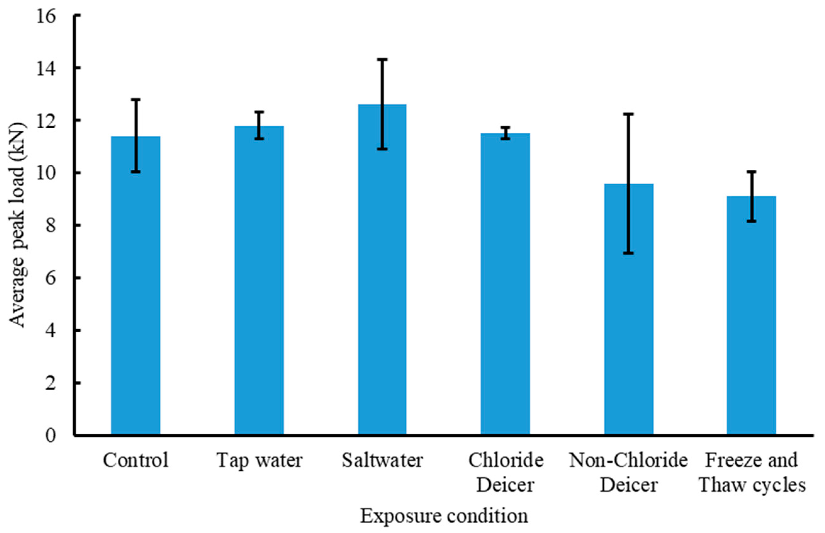
The load versus deflection curves for the concrete specimens exposed to freeze-and-thaw cycles in chloride-based deicer are shown in Figure 13d. The average maximum load was 11.5 kN, which was 0.42% higher than that one for the control specimens. On the other hand, the flexure behaviors of the non-chloride-based concrete specimens are presented in Figure 13e. Two specimens experienced premature failure at the maximum loads of 5.6 kN and 4.7 kN. The mode of failure for these two specimens was concrete failure around the CFRP without debonding. Figure 14a shows the large cracks that were formed in the first two specimens. By excluding the results of these two specimens, the maximum load was 9.6 kN, which was 15.7% less than the control specimens. The results confirmed side effects on the concrete strength due to the exposure to the non-chloride-based deicer, which caused failure in the concrete instead of the CFRP. Although the third specimen experienced debonding of the CFRP (see Figure 14b), there was much concrete, which was bound to the epoxy. The epoxy was firmly bound to the concrete surface. That was not the same case as with the tap water and saltwater exposures. The flexure curves for the concrete specimens undergoing freeze-and-thaw cycles in tap water are shown in Figure 13f. The average maximum load was 9.1 kN, which was 20.2% less than the control specimens. Deterioration occurred in the epoxy strength due to the exposure to freeze-and-thaw cycles in tap water. Comparisons of the three-point bending test results are presented in Figure 15. Additional comparisons between the average peak loads of each group with error bars are provided in Figure 16. In this figure, the bar heights represent the average peak load and the black error bar gives information on how the scatter of the results between different specimens of a given group. The measurements in the group of tap water are the most precise and the least precise results are for the group of non-chloride deicer. A previous study confirmed the same increase in the bond strength and peak loads after exposure to saline environments [29].
4. Conclusions
The durability of CFRP materials used for strengthening RC beams was tested under various environmental scenarios including subjection to immersion in deicing agents, tap water, and saltwater, freeze-and-thaw cycles, and outdoor environmental changes. Laboratory tests were performed to examine the influence of these environmental scenarios on the bond behavior between the CFRP and concrete. Two types of test setups were performed in this study, namely pull-off shearing and three-point bending. Forty-two concrete prisms with CFRP were prepared and tested by using the pull-off shearing setup. In addition, eighteen short concrete beams strengthened with an external CFRP were tested under three-point bending. Based on the experimental results, the following conclusions could be drawn:
- It was observed that as the period of exposure increased, a noticeable effect on the stiffness of the CFRP was observed.
- Tap water exposure had a greater impact on the CFRP–concrete bond strength and on the CFRP than the saltwater exposure. The strength was reduced after 60 days of exposure by an average of 5% and 26% for the saltwater and tap water exposures, respectively, for the 25 mm CFRP width.
- It can be seen that after 60 days of outdoor exposure, the strength of the CFRP was not affected. However, after 195 days, this environment had an adverse effect on the CFRP strength. Increasing the period of outdoor exposure tends to weaken the CFRP strength.
- From the three-point bending testing, it was observed that tap water showed a 3.6% increase in the bond strength compared to the control specimens. However, the saltwater showed a 10% increase in the bond strength.
- Chloride deicer slightly affected strength, whereas non-chloride deicer reduced the strength by 42%.
- In this study, it was observed that freeze-and-thaw cycles in tap water reduced the strength by 20.2% compared to the control specimens.
Author Contributions
Conceptualization, A.A.-K. and H.S.; data curation, A.E.-Z.; formal analysis, A.E.-Z.; investigation, A.E.-Z., M.M., and A.A.-K.; methodology, A.E.-Z. and M.M.; resources, M.M. and A.A.-K.; supervision, A.E.-Z. and H.S.; visualization, H.S.; writing—original draft, M.M. and A.A.-K.; writing—review & editing, A.E.-Z. All authors have read and agreed to the published version of the manuscript.
Funding
This research received no external funding.
Institutional Review Board Statement
Not applicable.
Informed Consent Statement
Not applicable.
Data Availability Statement
Not applicable.
Conflicts of Interest
The authors declare no conflict of interest.
References
- Hussain, Q.; Ruangrassamee, A.; Tangtermsirikul, S.; Joyklad, P.; Wijeyewickrema, A.C. Low-Cost Fiber Rope Reinforced Polymer (FRRP) Confinement of Square Columns with Different Corner Radii. Buildings 2021, 11, 355. [Google Scholar] [CrossRef]
- Rodsin, K.; Ali, N.; Joyklad, P.; Chaiyasarn, K.; Al Zand, A.W.; Hussain, Q. Improving stress-strain behavior of waste aggregate concrete using affordable glass fiber reinforced polymer (GFRP) composites. Sustainability 2022, 14, 6611. [Google Scholar] [CrossRef]
- Fan, M. Sustainable fiber-reinforced polymer composites in construction. Manag. Recycl. Reuse Waste Compos. 2010, 520–568. [Google Scholar] [CrossRef]
- Al-Saadi, N.T.K.; Al-Mahaidi, R.; Kamiran Abdouka, K. Bond behaviour between NSM CFRP strips and concrete substrate using single-lap shear testing with cement-based adhesives. Aust. J. Struct. Eng. 2016, 17, 28–38. [Google Scholar] [CrossRef] [Green Version]
- Haddad, R.H. An Anchorage System for Enhanced Bond Behavior between Carbon Fiber Reinforced Polymer Sheets and Cracked Concrete. Lat. Am. J. Solids Struct. 2019, 16. [Google Scholar] [CrossRef]
- Zhao, J.; Cai, G.; Cui, L.; Si Larbi, A.; Daniel Tsavdaridis, K. Deterioration of Basic Properties of the Materials in FRP-Strengthening RC Structures under Ultraviolet Exposure. Polymers 2017, 9, 402. [Google Scholar] [CrossRef] [Green Version]
- Soutis, C.; Turkmen, D. Moisture and Temperature Effects of the Compressive Failure of CFRP Unidirectional Laminates. Compos. Mater. 1997, 31, 832–849. [Google Scholar] [CrossRef]
- Li, S.; Hu, J.; Ren, H. The Combined Effects of Environmental Conditioning and Sustained Load on Mechanical Properties of Wet Lay-Up Fiber Reinforced Polymer. Polymers 2017, 9, 244. [Google Scholar] [CrossRef] [Green Version]
- Peng, H.; Liu, Y.; Cai, C.; Yu, J.; Zhang, J. Experimental investigation of bond between near-surface-mounted CFRP strips and concrete under freeze-thawing cycling. J. Aerosp. Eng. 2019, 32. [Google Scholar] [CrossRef]
- Jadooe, A.; Al-Mahaidi, R.; Abdouka, K. Bond behavior between NSM CFRP strips and concrete exposed to elevated temperature using cement-based and epoxy adhesives. J. Compos. Constr. 2017, 21. [Google Scholar] [CrossRef]
- Liu, S.; Pan, Y.; Li, H.; Xian, G. Durability of the Bond between CFRP and Concrete Exposed to Thermal Cycles. Materials 2019, 12, 515. [Google Scholar] [CrossRef] [PubMed] [Green Version]
- Zheng, X.H.; Huang, P.Y.; Guo, X.Y.; Huang, J.L. Experimental Study on Bond Behavior of FRP-Concrete Interface in Hygrothermal Environment. Int. J. Polym. Sci. 2016, 2016, 5832130. [Google Scholar] [CrossRef]
- Atadero, R.A.; Douglas, G.A.; Oscar, R.M. Long-Term Monitoring of Mechanical Properties of FRP Repair Materials. Available online: https://rosap.ntl.bts.gov/view/dot/26179 (accessed on 1 July 2013).
- Mohammadi, M.; Mostofinejad, D. CFRP-to-concrete bond behavior under aggressive exposure of sewer chamber. J. Compos. Mater. 2021, 55, 3359–3373. [Google Scholar] [CrossRef]
- Taukta, C.; Buyukozturk, O. Conceptual model for prediction of FRP-concrete bond strength under moisture cycles. J. Compos. Constr. 2011, 15, 743–756. [Google Scholar] [CrossRef] [Green Version]
- Pan, Y.; Xian, G.; Silva, M.A.G. Effects of water immersion on the bond behavior between CFRP plates and concrete substrate. Constr. Build. Mater. 2015, 101, 326–337. [Google Scholar] [CrossRef]
- Lu, Y.; Zhu, T.; Li, S.; Liu, Z. Bond Behavior of Wet-Bonded Carbon Fiber-Reinforced Polymer-Concrete Interface Subjected to Moisture. Int. J. Polym. Sci. 2018, 2018, 3120545. [Google Scholar] [CrossRef] [Green Version]
- Medeiros, M.H.F.; Gobbi, A.; Réus, G.C.; Helene, P. Reinforced concrete in marine environment: Effect of wetting and drying cycles, height and positioning in relation to the sea shore. Constr. Build. Mater. 2013, 44, 452–457. [Google Scholar] [CrossRef]
- Ragab, A.M.; Elgammal, M.A.; Hodhod, O.A.; Ahmed, T.E. Evaluation of field concrete deterioration under real conditions of seawater attack. Constr. Build. Mater. 2016, 119, 130–144. [Google Scholar] [CrossRef]
- Ceroni, F.; Bonati, A.; Galimberti, V.; Occhiuzzi, A. Effects of Environmental Conditioning on the Bond Behavior of FRP and FRCM Systems Applied to Concrete Elements. J. Eng. Mech. 2018, 144. [Google Scholar] [CrossRef]
- Green, M.F.; Bisby, L.A.; Beaudoin, Y.; Labossière, P. Effect of freeze-thaw cycles on the bond durability between fibre reinforced polymer plate reinforcement and concrete. Can. J. Civ. Eng. 2000, 27, 949–959. [Google Scholar] [CrossRef]
- ASTM D7522/D7522M-21; Standard Test Method for Pull-Off Strength for FRP Laminate Systems Bonded to Concrete or Masonry Substrates. ASTM International: West Conshohocken, PA, USA, 2021.
- Gartner, A.; Douglas, E.P.; Dolan, C.W.; Hamilton, H.R. Small beam bond test method for CFRP composites applied to concrete. J. Compos. Constr. 2011, 15, 52–61. [Google Scholar] [CrossRef]
- Yan, L.; Chouw, N. Effect of Water, Seawater and Alkaline Solution Ageing on Mechanical Properties of Flax Fabric/Epoxy Composites Used for Civil Engineering Applications. Constr. Build. Mater. 2015, 99, 118–127. [Google Scholar] [CrossRef]
- ASTM C78/C78M; Standard Test Method for Flexural Strength of Concrete. ASTM International: West Conshohocken, PA, USA, 2018. [CrossRef]
- ASTM C31/C31M-21a; Standard Practice for Making and Curing Concrete Test Specimens in the Field. ASTM International: West Conshohocken, PA, USA, 2021. [CrossRef]
- ASTM C666/C666M-15; Standard Test Method for Resistance of Concrete to Rapid Freezing and Thawing. ASTM International: West Conshohocken, PA, USA, 2015.
- ASTM C672/C672M-12; Standard Test Method for Scaling Resistance of Concrete Surfaces Exposed to Deicing Chemicals. ASTM International: West Conshohocken, PA, USA, 2012.
- Al-Tamimi, A.K.; Hawileh, R.A.; Abdalla, J.A.; Rasheed, H.A.; Al-Mahaidi, R. Durability of the bond between CFRP plates and concrete exposed to harsh environments. J. Mater. Civ. Eng. 2005, 27. [Google Scholar] [CrossRef]
Figure 1.
Preparation of specimens. (a) Rectangular concrete prisms. (b) The CFRP bonded to the concrete blocks.
Figure 1.
Preparation of specimens. (a) Rectangular concrete prisms. (b) The CFRP bonded to the concrete blocks.
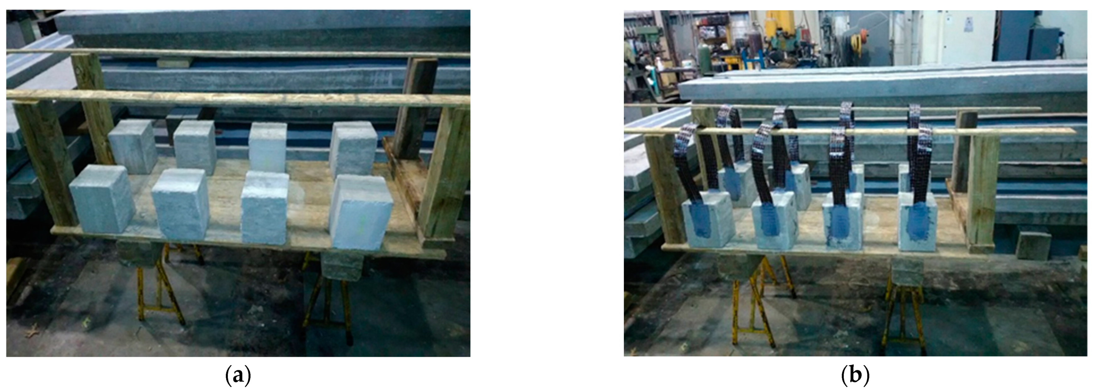
Figure 2.
The full immersion procedures for the specimens of the pull-off shearing tests. (a) The saltwater exposure. (b) The tap water exposure. (c) The outdoor exposure.
Figure 2.
The full immersion procedures for the specimens of the pull-off shearing tests. (a) The saltwater exposure. (b) The tap water exposure. (c) The outdoor exposure.
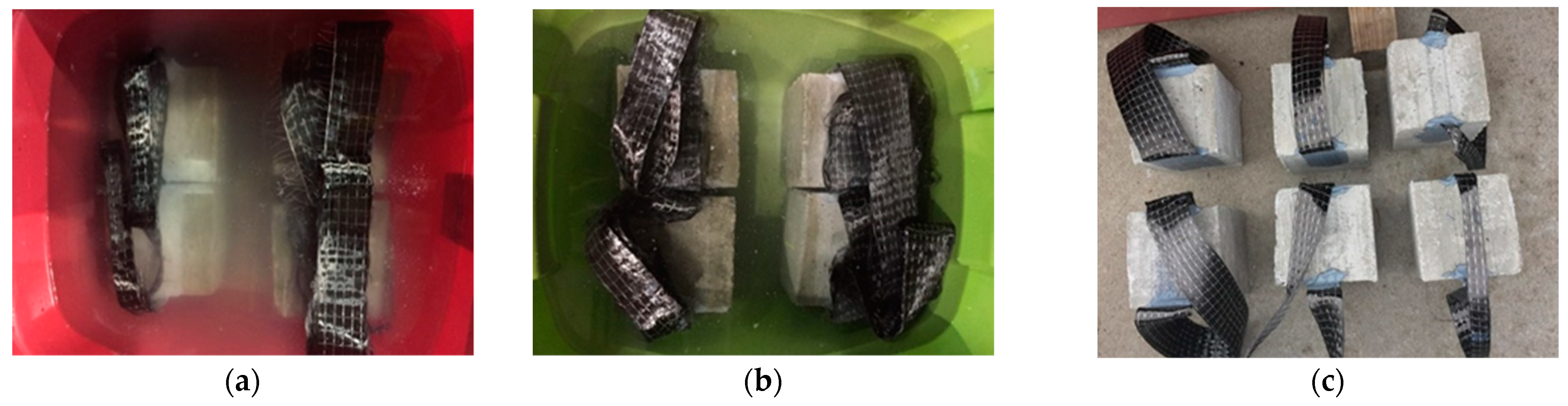
Figure 3.
Outdoor environmental changes. (a) Average temperature and precipitation. (b) Humidity data.
Figure 3.
Outdoor environmental changes. (a) Average temperature and precipitation. (b) Humidity data.
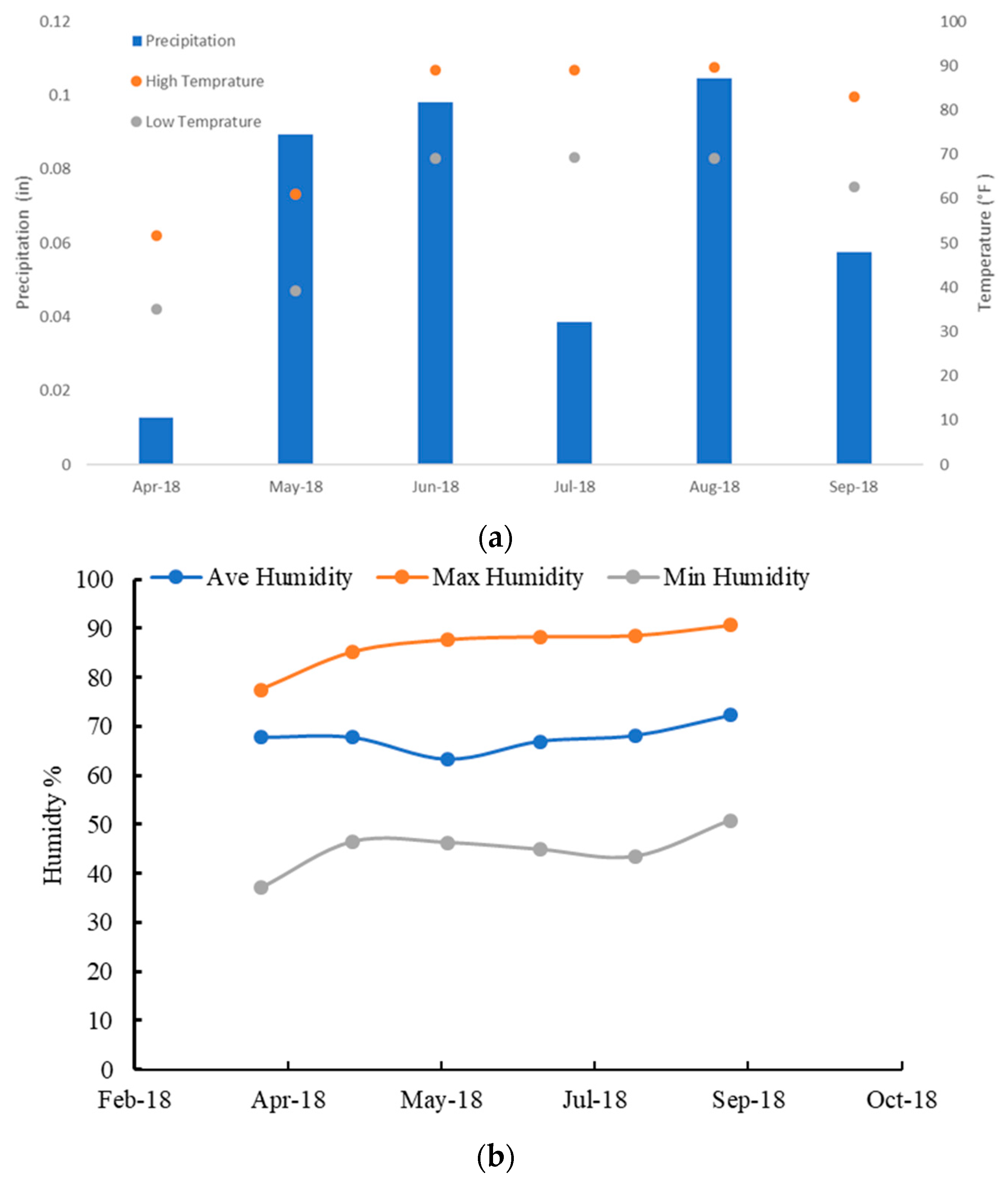
Figure 4.
The pull-off shearing test set-up. (Dimensions are in mm).
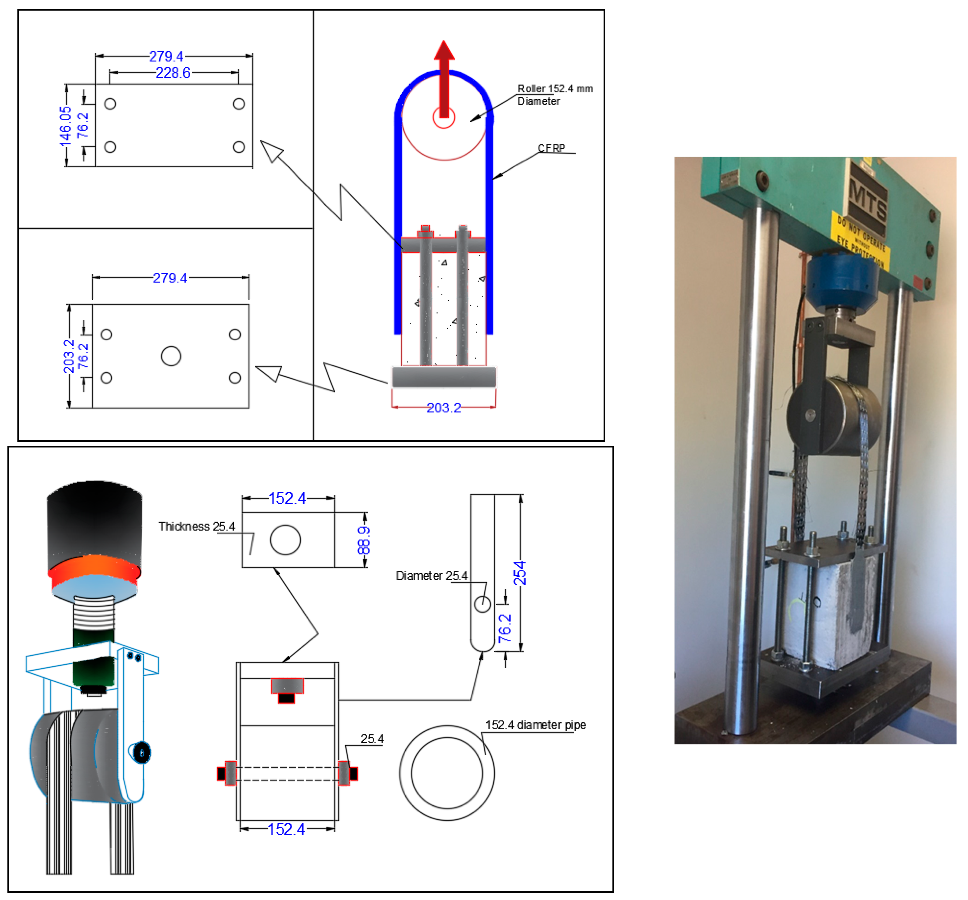
Figure 5.
Preparation of the strengthened pre-notched concrete prisms. (a) Crack initiation. (b) Application of the CFRP sheets to concrete. (c) Strengthened specimens.
Figure 5.
Preparation of the strengthened pre-notched concrete prisms. (a) Crack initiation. (b) Application of the CFRP sheets to concrete. (c) Strengthened specimens.
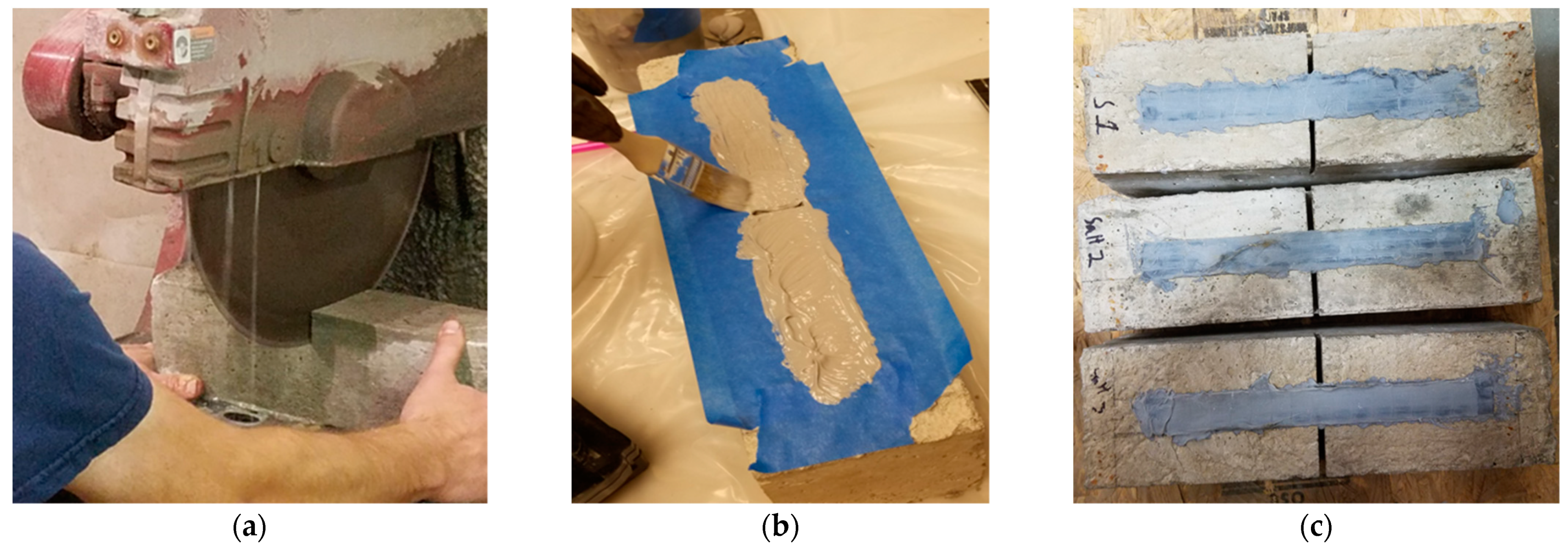
Figure 6.
Three-point bending test set-up.
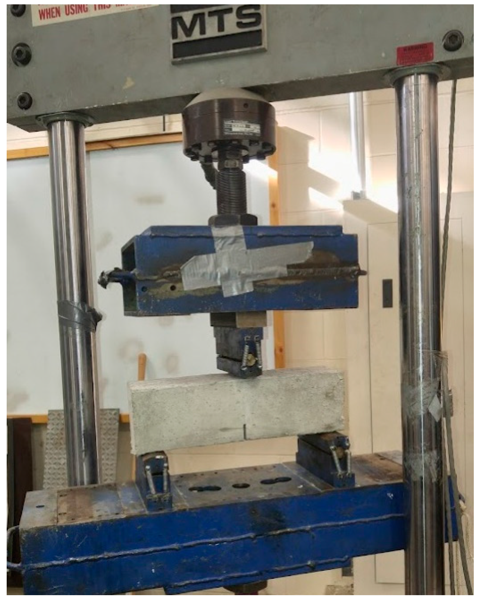
Figure 7.
Load versus deflection curves after 60 days of exposure. (a) CFRP strip width of 25 mm (1.0 in.). (b) CFRP strip width of 50 mm (2.0 in.). (c) CFRP strip width of 75 mm (3.0 in.).
Figure 7.
Load versus deflection curves after 60 days of exposure. (a) CFRP strip width of 25 mm (1.0 in.). (b) CFRP strip width of 50 mm (2.0 in.). (c) CFRP strip width of 75 mm (3.0 in.).
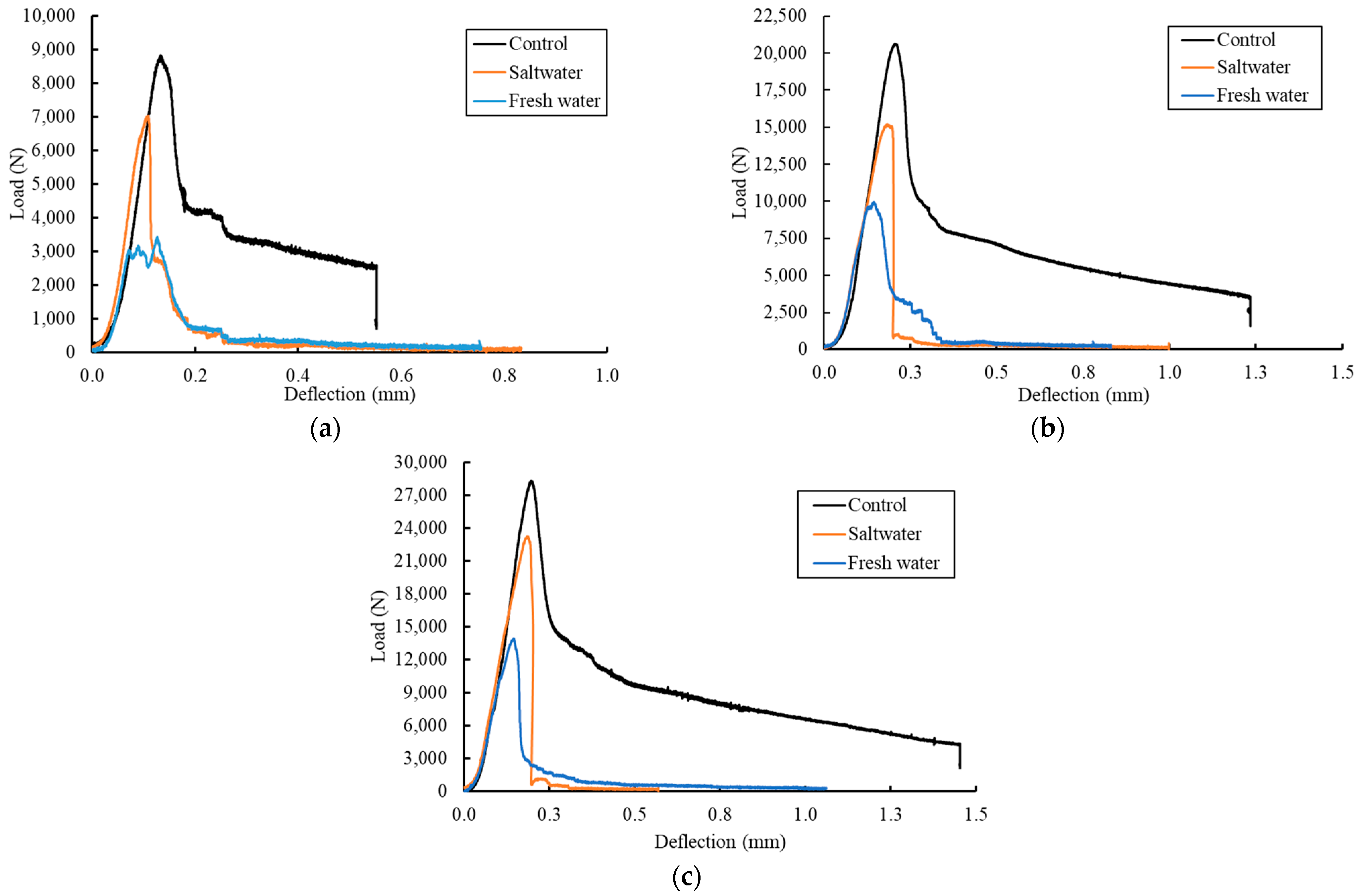
Figure 8.
Typical failure mode after 60 days of exposure. (a) 25 mm width. (b) 50 mm width. (c) 75 mm width.
Figure 8.
Typical failure mode after 60 days of exposure. (a) 25 mm width. (b) 50 mm width. (c) 75 mm width.
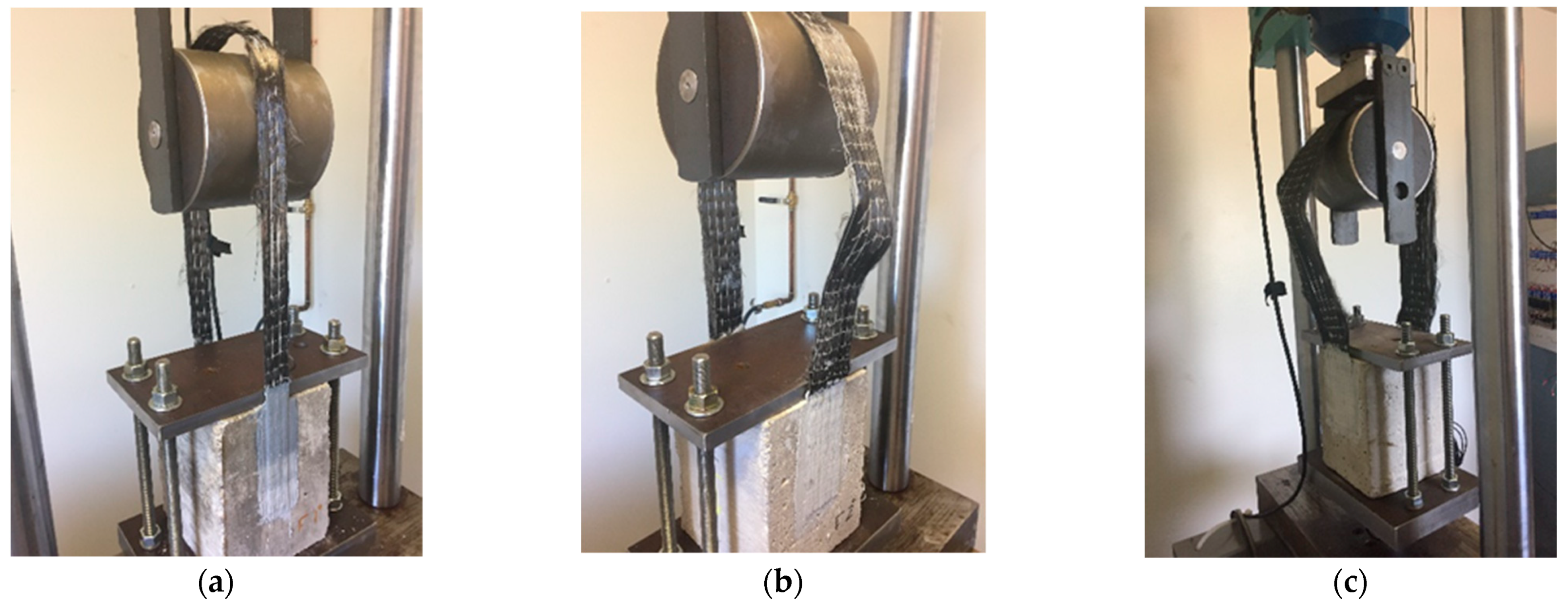
Figure 9.
Effect of 60 days of exposure on the CFRP strength.
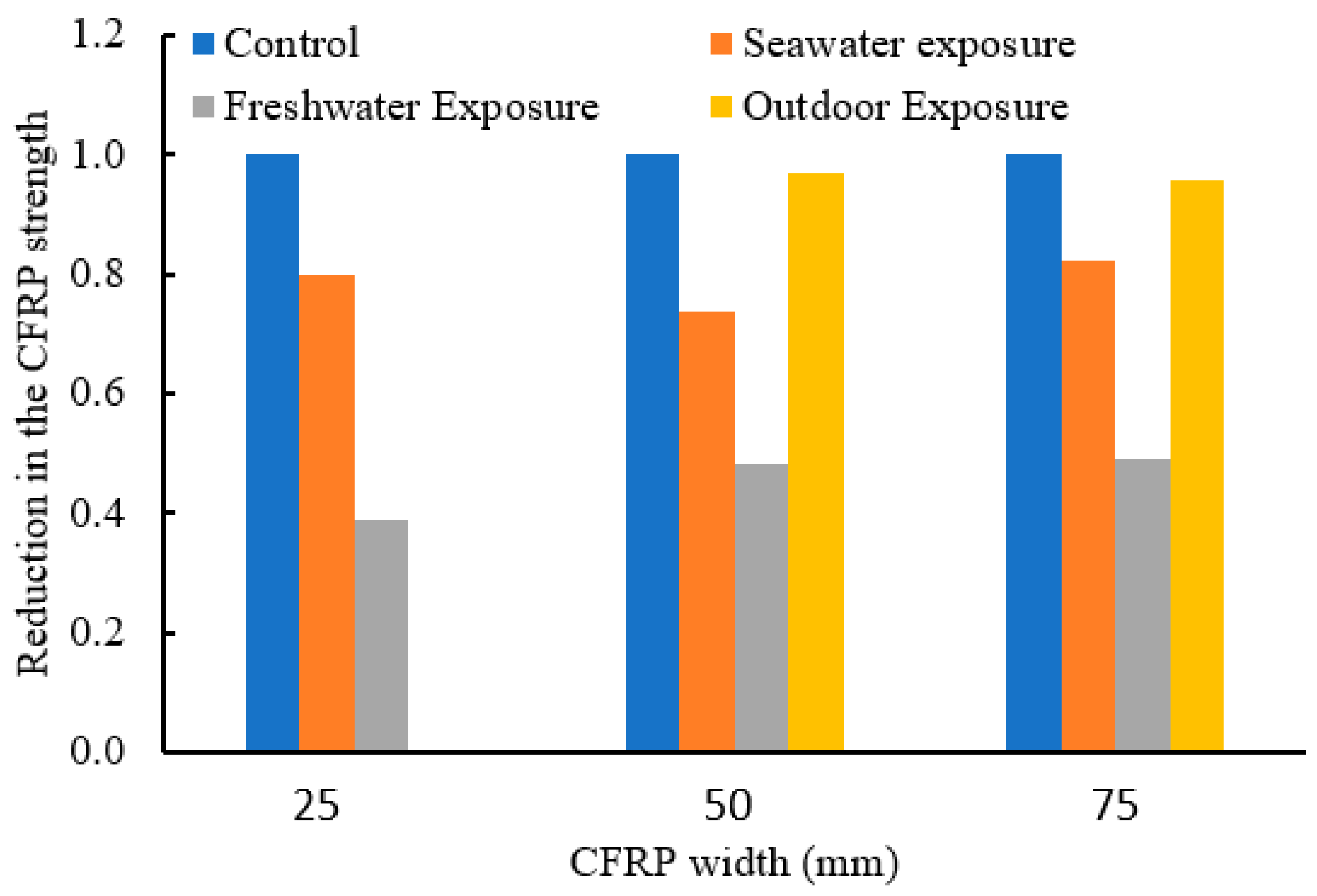
Figure 10.
Load versus deflection curves after 195 days of exposure. (a) CFRP strip width of 25 mm (1.0 in.). (b) CFRP strip width of 50 mm (2.0 in.). (c) CFRP strip width of 75 mm (3.0 in.).
Figure 10.
Load versus deflection curves after 195 days of exposure. (a) CFRP strip width of 25 mm (1.0 in.). (b) CFRP strip width of 50 mm (2.0 in.). (c) CFRP strip width of 75 mm (3.0 in.).
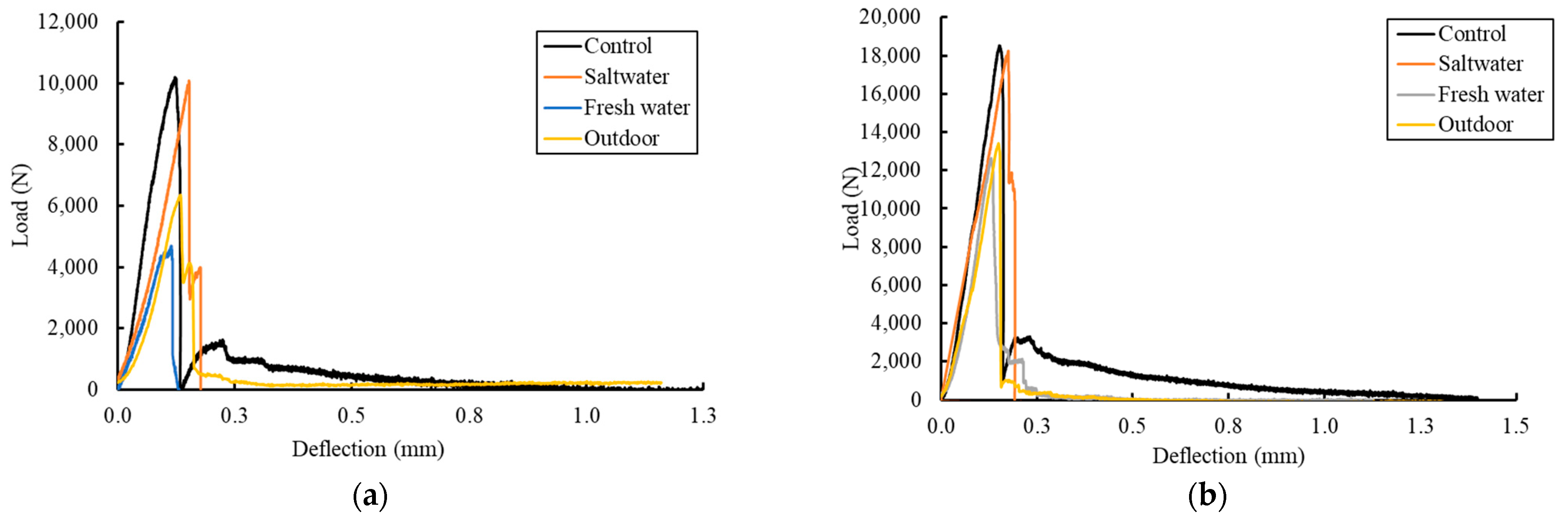
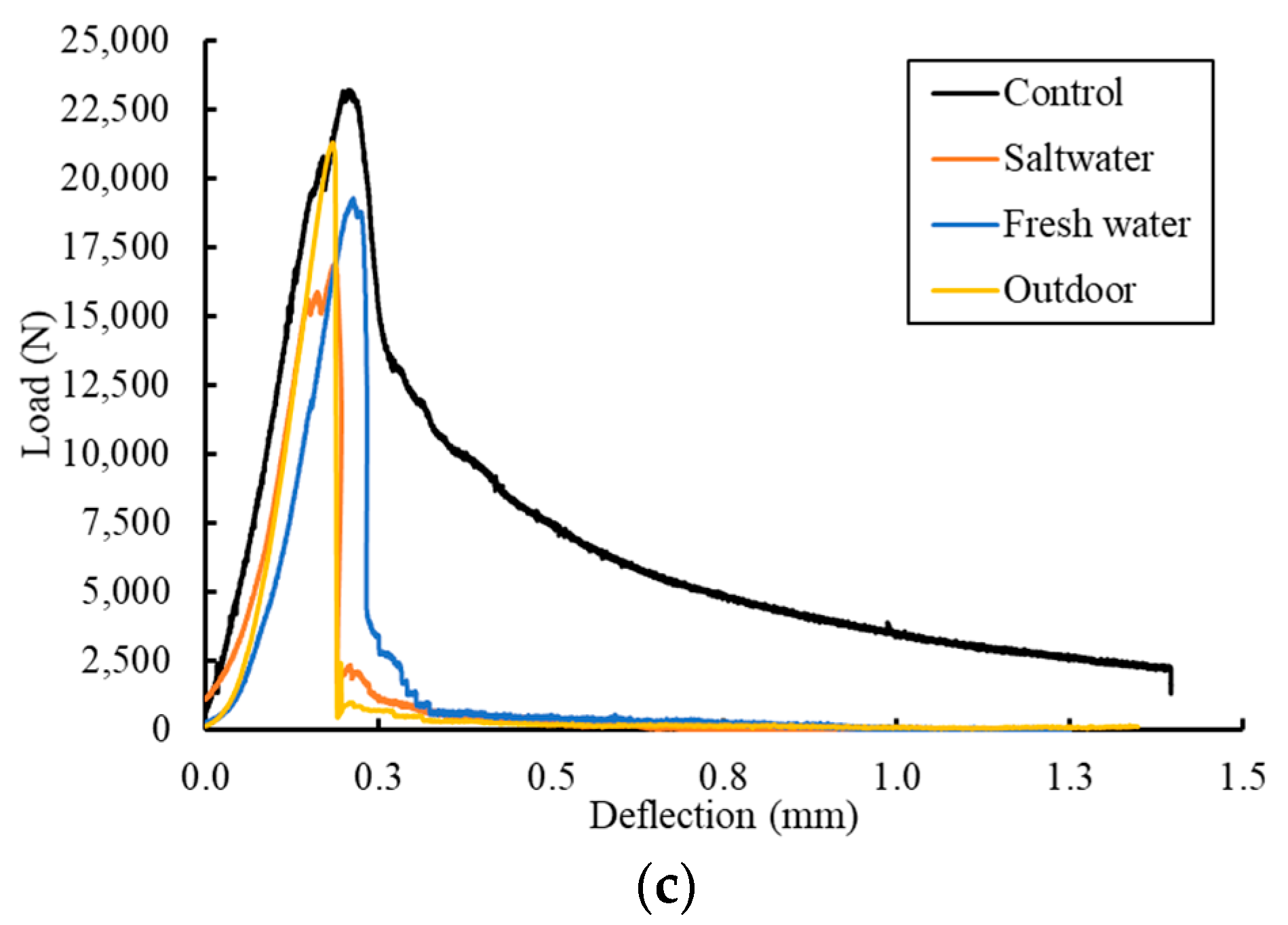
Figure 11.
Effect of 195 days of exposure on CFRP strength.
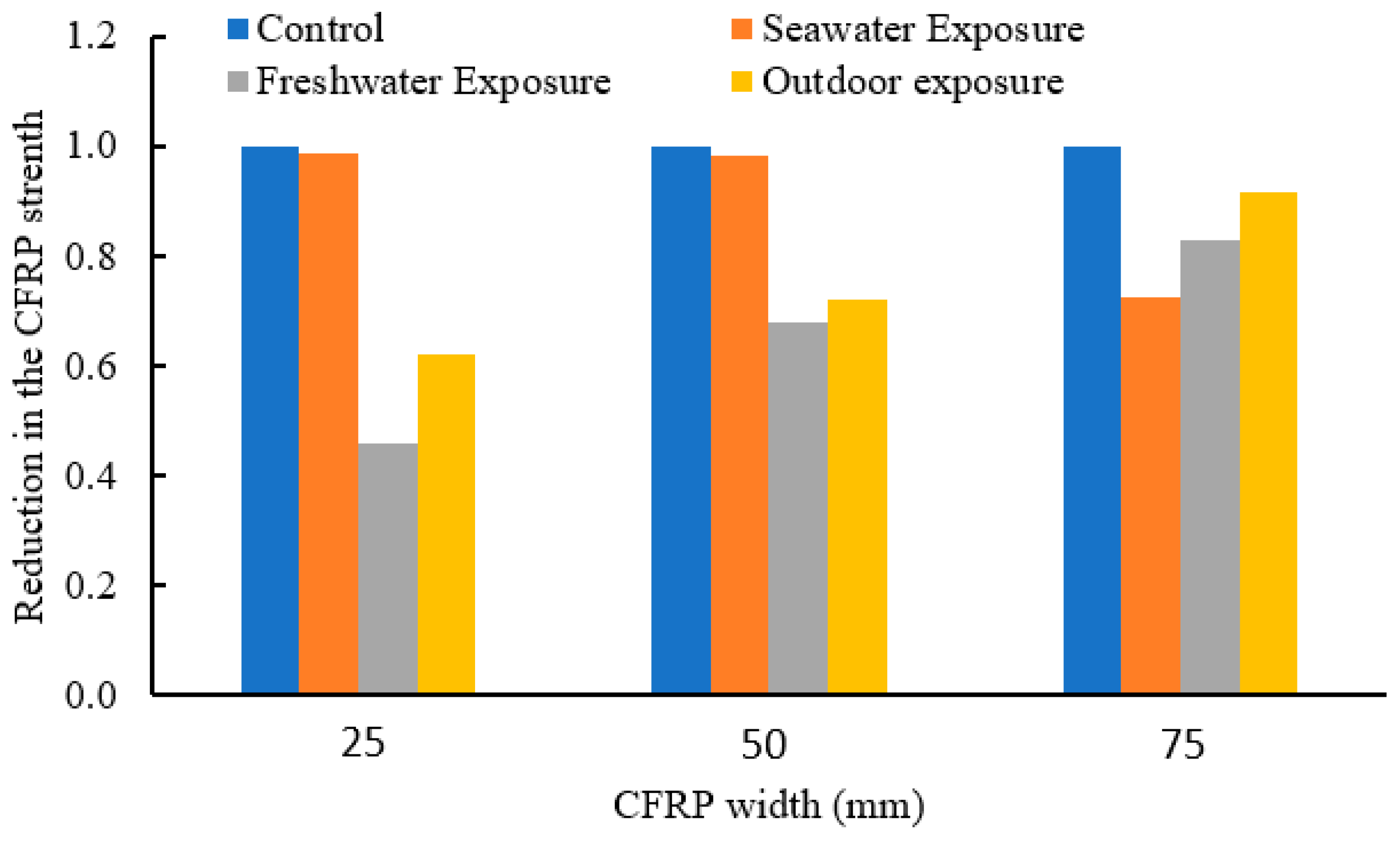
Figure 12.
Effect of exposure time on the strength of the 75 mm CFRP.
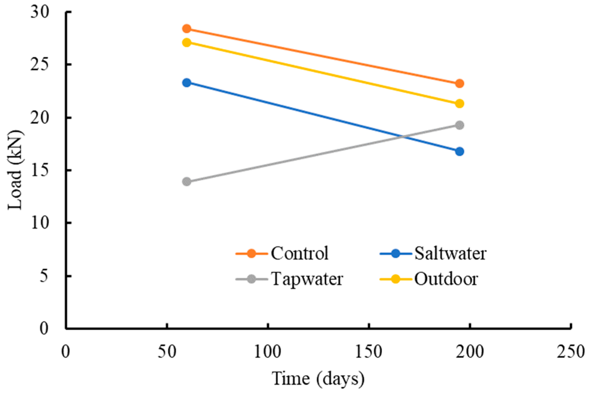
Figure 13.
Load deflection response for the effect of different environmental exposures of the three-point bending test results. (a) Control specimens. (b) Wet-and-dry cycles in tap water. (c) Wet-and-dry cycles in saltwater. (d) Freeze-and-thaw cycles in chloride deicer. (e) Freeze-and-thaw cycles in non-chloride deicer. (f) Freeze-and-thaw cycles in tap water.
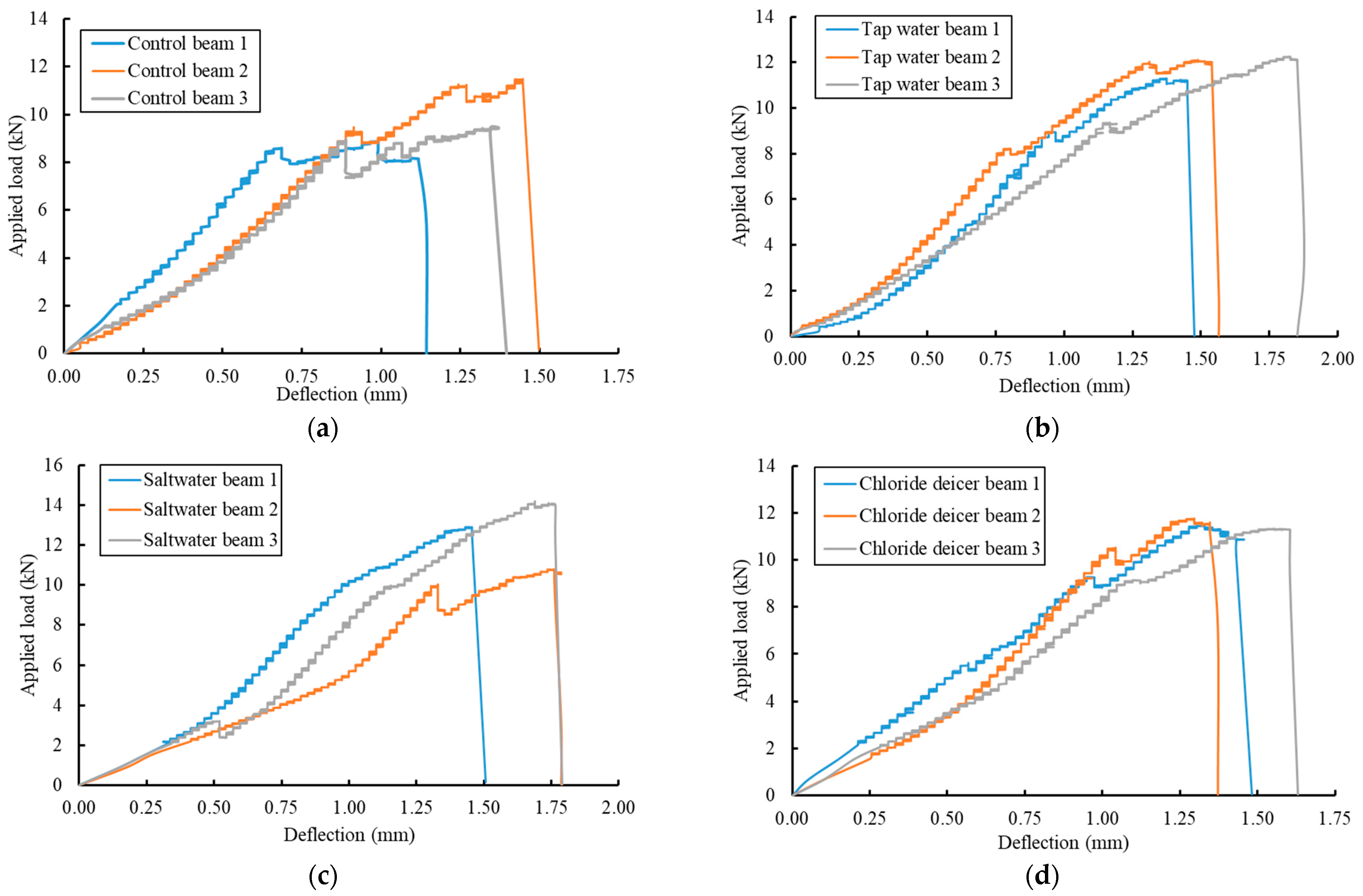
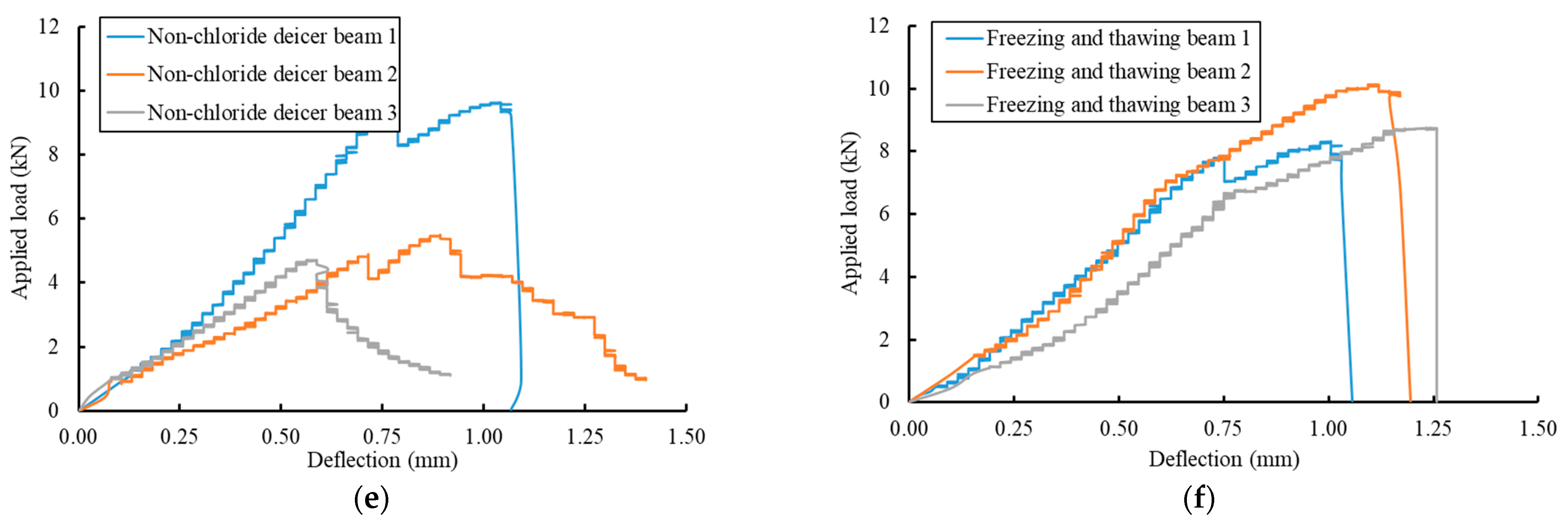
Figure 14.
Non-chloride-based deicer concrete deterioration. (a) Failure of concrete around the CFRP. (b) Mode of failure.
Figure 14.
Non-chloride-based deicer concrete deterioration. (a) Failure of concrete around the CFRP. (b) Mode of failure.
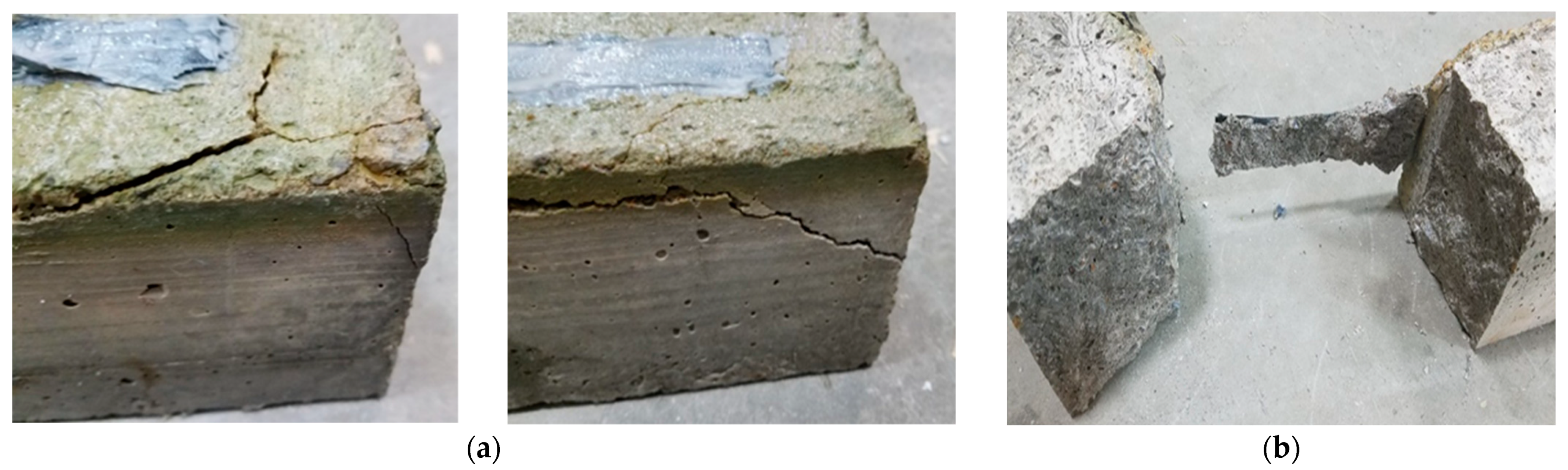
Figure 15.
Load deflection response comparisons of the three-point bending test results. (a) Wet-and-dry cycles. (b) Freeze-and-thaw cycles.
Figure 15.
Load deflection response comparisons of the three-point bending test results. (a) Wet-and-dry cycles. (b) Freeze-and-thaw cycles.
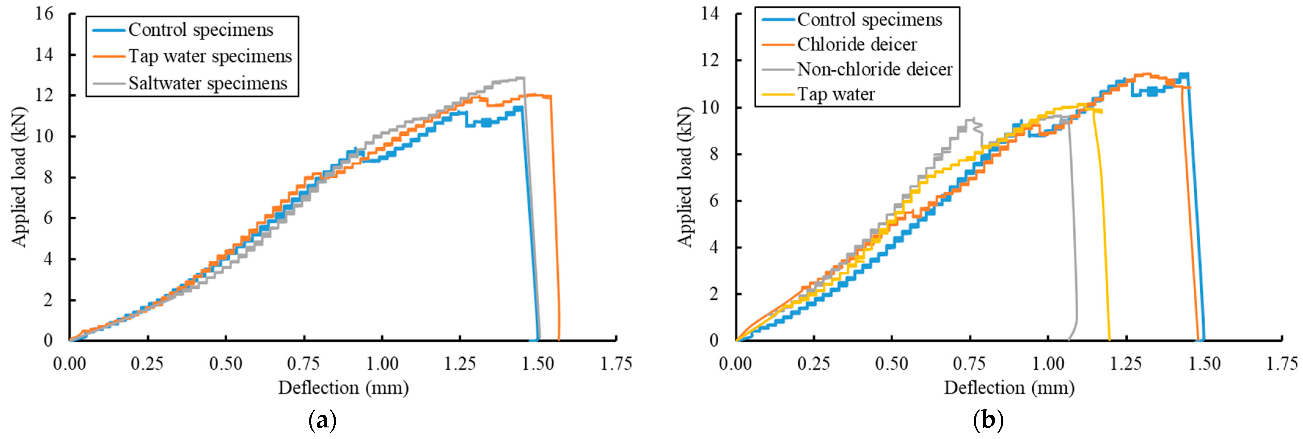
Figure 16.
Comparisons between the average peak loads of each group with error bars.

Table 1.
Summary of exposure conditions used to weather the specimens.
| Exposure Condition | Exposure Times (Days) | CFRP Width (mm) | Number of Specimens |
|---|---|---|---|
| Control | 60 and 195 | 25, 50, and 75 | 6 |
| Saltwater immersion | 60 and 195 | 25, 50, and 75 | 6 |
| Outdoor environment | 60 and 195 | 25, 50, and 75 | 6 |
| Immersion in tap water | 60 and 195 | 25, 50, and 75 | 6 |
Table 2.
Composition/information on ingredients (provided by EnviroTech Services, Inc., Greeley, CO, USA).
Table 2.
Composition/information on ingredients (provided by EnviroTech Services, Inc., Greeley, CO, USA).
| MeltDown Apex | Apogee | ||
|---|---|---|---|
| Component | Amount | Component | Amount |
| Water | 65–75% | Water | Balance |
| Magnesium Chloride | 25–35% | Proprietary Organic Based Components | 75–85% |
| Corrosion Inhibitor | <1.0% | Proprietary Performance Additive | 2–6% |
| Performance Additive | <1.0% | Relative Density | 1.15–1.27 |
| Relative Density | 1.24–1.34 | ||
Table 3.
Mechanical properties of CFRP strips (provided by the manufacturer).
| Fiber orientation | 0° |
| Areal weight | 450 g/m2 |
| Fabric design thickness | 0.38 mm (based on the total area of carbon fibers) |
| Tensile strength of fibers | 986 MPa |
| Tensile E—modulus of fibers | 95837 MPa |
| Elongation at break | 2.1% |
Table 4.
Mechanical properties of epoxy adhesive (provided by the manufacturer).
| Appearance | Yellow |
| Density | 1.1 g/cm3 |
| Mixing ratio | 4:1 by weight (at +25 C) |
| Open time | 30 min |
| Tensile strength | 33.8 MPa |
| E-modulus (Flexural) | 3488 MPa |
| Flexural strength | 60.7 MPa |
Table 5.
Peak loads from the pull-off shearing tests after 60 and 195 days of exposure.
| Exposure Condition | CFRP Width (mm) | 60 Days of Exposure | 195 Days of Exposure | ||
|---|---|---|---|---|---|
| Peak Load (kN) | % Change | Peak Load (kN) | % Change | ||
| Control | 25 | 8.8 | - | 10.2 | - |
| 50 | 20.6 | - | 18.5 | - | |
| 75 | 28.4 | - | 23.2 | - | |
| Saltwater | 25 | 7.0 | 20 | 10.1 | 1 |
| 50 | 15.2 | 26 | 18.3 | 2 | |
| 75 | 23.3 | 18 | 16.8 | 27 | |
| Tap water | 25 | 3.4 | 61 | 4.7 | 54 |
| 50 | 10.0 | 52 | 12.6 | 32 | |
| 75 | 13.9 | 51 | 19.3 | 17 | |
| Outdoor environment | 25 | Lost data * | - | 6.4 | 38 |
| 50 | 20.0 | 3 | 13.4 | 28 | |
| 75 | 27.1 | 5 | 21.3 | 8 | |
* The test data was lost due to an error from the MTS loading machine.
Table 6.
Peak loads from the three-point bending tests after 30 cycles of exposure.
| Exposure Condition | Peak Load (kN) | % Change | Failure MODE |
|---|---|---|---|
| Control | 11.4 | - | Debonding |
| Tap water | 11.8 | +3.5 | Debonding |
| Saltwater | 12.6 | +10.5 | Debonding |
| Chloride Deicer | 11.5 | +0.8 | Debonding |
| Non-Chloride Deicer | 9.6 | −15.7 | Debonding |
| Freeze and Thaw cycles | 9.1 | −20.2 | Debonding |
Publisher’s Note: MDPI stays neutral with regard to jurisdictional claims in published maps and institutional affiliations. |
© 2022 by the authors. Licensee MDPI, Basel, Switzerland. This article is an open access article distributed under the terms and conditions of the Creative Commons Attribution (CC BY) license (https://creativecommons.org/licenses/by/4.0/).
Share and Cite
MDPI and ACS Style
Al-Khafaji, A.; El-Zohairy, A.; Mustafic, M.; Salim, H. Environmental Impact on the Behavior of CFRP Sheet Attached to Concrete. Buildings 2022, 12, 873. https://doi.org/10.3390/buildings12070873
AMA Style
Al-Khafaji A, El-Zohairy A, Mustafic M, Salim H. Environmental Impact on the Behavior of CFRP Sheet Attached to Concrete. Buildings. 2022; 12(7):873. https://doi.org/10.3390/buildings12070873
Chicago/Turabian StyleAl-Khafaji, Ayssar, Ayman El-Zohairy, Mirnes Mustafic, and Hani Salim. 2022. "Environmental Impact on the Behavior of CFRP Sheet Attached to Concrete" Buildings 12, no. 7: 873. https://doi.org/10.3390/buildings12070873
Note that from the first issue of 2016, this journal uses article numbers instead of page numbers. See further details here.