
The Classification and Mechanism of Microcrack Homogenization Research in Cement Concrete Based on X-ray CT

1
School of Civil Engineering, Northwest Minzu University, Lanzhou 730030, China
2
School of Highway, Chang’an University, Xi’an 710064, China
*
Authors to whom correspondence should be addressed.
Buildings 2022, 12(7), 1011; https://doi.org/10.3390/buildings12071011
Submission received: 25 May 2022
/
Revised: 4 July 2022
/
Accepted: 8 July 2022
/
Published: 14 July 2022
(This article belongs to the Special Issue Sustainable Building Infrastructure and Resilience)
Abstract
:Old cement pavement directly overlaid with an asphalt layer produces many reflection cracks. Using microcrack homogenization technology to treat old cement pavement can effectively reduce the occurrence of reflection cracks. Micro-crack homogenization is relatively mature at the technical level; however, there is relatively little research on its mechanism. To evaluate the microcrack effect of old cement pavement, we conducted core sampling on a project road section after the appearance of microcracks. The core samples were sliced by X-ray tomography (X-ray CT). The mesostructure of the core samples was obtained. The core sample was further divided into microscopic cracks and macroscopic cracks according to the length and width of the crack. The development characteristics of cracks were subdivided into type I-III microcracks and type I-IV cracks. The core-drilling sample was divided into 5652 CT images. The statistical results showed that there were 3582 type-I microcracks, 3197 type-II microcracks, and 1835 type-III microcracks. Among the specimens, the minor proportion of microcracks was 32.87%, the most significant proportion was 100.00%, and the average ratio was 47.51%. Furthermore, the cracks development law and formation mechanism were analyzed based on CT images and cracking statistics. The results showed: (1) The microcrack homogenization process produced many microcracks in the test section and achieved a specific microcrack effect. (2) The cracks produced by the microcrack homogenization process tended to develop along the transition zone of the aggregate–cement mortar interface. The development of microcracks was mainly related to the aggregates’ shape and gradation, as well as the energy required to generate cracks. The research conclusions of this paper can be used as a theoretical basis for the optimization and improvement of the microcrack homogenization process.
1. Introduction
Cement concrete pavement is the primary type of rural road in my country. With the rapid development of my country’s transportation industry, many cement pavement surfaces have cracks and diseases, requiring urgent maintenance. Old cement pavement directly overlaid with an asphalt layer (commonly known as “white to black” [1]) is a relatively common maintenance method at present. It can improve the performance of pavement, increase the bearing capacity, and prolong its service life. However, early reflection cracks in pavement are more serious [2], and a void at the bottom of the slab also affects the overlay effect.
To reduce or inhibit the occurrence of reflective cracks, domestic and foreign experts propose pretreating the old cement pavement before overlaying. Pretreatment methods include petrification, portal crushing, fracturing and pressure stabilization, microcrack homogenization, etc. The pavement made by crushing or gantry crushing suffers a significant loss of strength and is used as a sub-base, which requires a thicker asphalt layer or a different base [3,4]. However, the strength loss of old pavement with fracturing and compression stabilization is less than that of the first two methods. It is suitable for overlaying a thin asphalt layer. A large compaction load mainly impacts the base layer, roadbed, culvert, and surrounding structures [5]. Microcrack homogenization technology is an emerging cement pavement crushing technology. It imposes small impact load to make the old road crack after disposal without breaking, retain the strength of the old road to a considerable extent. It can also be combined with grouting technology to improve the homogenization of the old highway, effectively overcoming the problem of reflection cracks and reducing the thickness of the overlay [6]. This technology has been verified in dozens of cement pavement resurfacing projects in China, such as the S305 Fuqing section, the Hengnan section of Hengyang National Highway 322, and Xianyang Baoquan Road [7,8,9]. The local standard of Henan Province (DB41/T963-2014) and the local standard of Chuzhou City (DB34/T-2018) were released and implemented and have since been popularized and applied in many provinces and cities in China. With positive economic and social benefits, this construction technology is relatively mature, although research on its theoretical basis is relatively lacking. It is necessary to research the microcrack homogenization mechanism [10].
X-ray CT scanning technology has intuitive and non-destructiveness characteristics, providing useful statistics on the microstructure of concrete materials [11]. X-ray CT scanning technology has become an essential tool used by many researchers to analyze concrete microstructures and is widely used in active pavement testing. Morgan et al. [12] applied X-ray CT scanning technology to concrete inspection for the first time, using a caesium-137 isotope source to provide a 662 keV photon beam. Aggregates, voids, and cracks are displayed by detecting and counting each emitted photon. Lawer et al. [13] analyzed rectangular cement concrete specimens containing sand and graphite aggregate by X-ray microscopic tomography (XMT). The results showed that XMT had apparent advantages in studying large fractures and the influence of internal characteristics on the fracture process. Suzuki et al. [14] detected crack distribution of freezing–thawing concrete by using AE and X-ray CT and proposed scalar damage parameters to quantitatively evaluate the internal damage of concrete. Tian W. et al. [15] studied the process of internal damage of concrete in dynamic load uniaxial compression using real-time scanning and observation of X-ray CT scanning technology, successfully exploring the mesoscopic dynamic damage process of concrete. Zhou S. et al. [16] and Fan W. et al. [17] established a three-dimensional mesoscopic model of concrete using X-ray CT scanning technology; they simulated the mesoscopic damage and macroscopic properties of concrete, respectively. Li S. et al. [18] qualitatively analyzed the distribution of substances in each pavement layer through two-dimensional slices obtained by X-ray CT scanning and studied the influence of voidage and density of the asphalt mixture on the performance of the overlay, providing a reference for quality control and material selection in reconstruction and expansion projects.
The crack generation mechanism is analyzed from the perspectives of fracture mechanics, damage mechanics, as well as the principle of minimum energy consumption and mesomechanics. In 1920, Griffith [19] proposed fracture mechanics theory by studying brittle materials, such as glass. He pointed out that a crack will continue to expand if the system’s total energy decreases due to expansion of the crack. In the 1860s, Kaplan [20] first introduced fracture mechanics to concrete, using the theoretical viewpoint of fracture mechanics to study the failure characteristics of defective concrete. Concrete beams with simulated cracks were tested using analysis and direct test methods. The critical strain energy release rate predicts the fracture strength of concrete with cracks. The two-parameter model proposed by Jenq and Shah [21,22] accurately predicts the load-crack opening displacement of 40 beams of different sizes using a method to calculate size-independent fracture toughness parameters. The equivalent crack model proposed by Karihaloo et al. [23] further developed the fracture theory based on heterogeneous aggregate materials, providing a method to determine the fracture energy according to the measured total stress–strain relationship and confirming the applicability of fracture mechanics to concrete. The virtual fracture model proposed by Hillerborg and Petersson et al. [24] combines fracture mechanics with finite element analysis to establish a new method for computationally simulating fracture propagation. Dougill [25] applied damage mechanics theory to concrete research for the first time from the perspective of path dependence and coupling of degradation and plastic deformation. Krajcinovic [26] introduced a concept similar to plastic yield surface under quasistatic loading, small deformation, and isothermal conditions and established a damage evolution equation derived from the damaged surface. The results obtained by this model match well with the actual cracking of the concrete. The results show the superiority of damage mechanics in analyzing the internal damage and cracking of concrete. Li J. [27] proposed a concrete mesodamage physical model to explain the damage evolution characteristics of high-performance concrete at the meso-level, further improving the basic framework of “Random Damage Mechanics of Concrete”. In 1993, Zhou Z. [28] summarized the relevant theories of “Plastic Mechanics, Fracture Mechanics and Continuum Mechanics”, proposed the principle of minimum energy consumption, and explained plastic fracture of materials from the perspective of energy. Tang S. et al. [29] and Wang H. [30] further developed this theory by establishing the damage evolution equation, applying the 3D elastic–plastic finite element method to simulate crack propagation, using the principle of minimum energy dissipation for damage analysis of cement concrete. Wittmann [31] first studied the voids and cracks of cement concrete at a mesoscale. The macroscopic fracture mechanism should be analyzed by mesomechanics. Zampini et al. [32] used environmental scanning electron microscopy (ESEM) to record the sequence of microstructural changes at the cement mortar–aggregate interface, describing the evolution of cement concrete’s mesostructure for the first time.
In the present study, we conducted core sampling on a project road section after microcrack homogenization treatment based on the above research status. X-ray CT was used to obtain internal structural images of the pavement core samples following microcracking for statistical analysis. The purpose of this paper is to first classify cracks after microcrack homogenization according to the length, width, and development characteristics of the cracks. Next, the number and proportion of microcracks were counted. The construction effect was evaluated with respect to the microcrack homogenization process. Furthermore, different types of fractures were compared and analyzed based on “Fracture Mechanics, Damage Mechanics, Minimum Energy Dissipation Principle and Meso-mechanics”. The cause and mechanism of the microcrack homogenization process are revealed, providing theoretical support for further development of the microcrack homogenization process. Finally, feasible suggestions are given for further improving the treatment effect of microcracks on cement pavement from the two perspectives of optimizing cement–concrete mix ratio design and promoting further development of the microcrack homogenization process.
1.1. X-ray CT Scanning Technology
X-ray CT testing was used to study the microstructure of cement concrete core samples. X-ray CT scanning technology is a standard method to obtain images of the internal structure of cement concrete. The image data can be used to analyze damage. Three views of a slice and its 3D appearance are shown in Figure 1.
X-rays can be used to perform non-destructive testing on substances due to their short wavelength and considerable penetration depth. The working principle of X-ray CT non-destructive testing equipment is to use the penetration effect of X-rays and substances. When an X-ray beam with constant energy passes through the object to be examined, the transmitted power received by the detector is modulated due to the attenuation coefficients of each volume element in each transmission direction. According to a specific image reconstruction algorithm, a non-overlapping tomographic image can be generated of the inspected workpiece. Computer topological imaging technology can then be used to reconstruct a three-dimensional image.
The CT equipment model used in this paper is German YXLon-YTU225. Its scanning accuracy is as high as 0.005 mm, with a scanning range of 140 × 140 × 140 mm, as shown in Figure 2. The samples were collected via random core sampling in cement pavement after microcrack homogenization. The seven samples obtained by the core drilling were named K4+950−1, K4+950−2, K5+000, K6+000, K8+100, K8+200, and K8+300 samples according to the road section labels. The size of the core drilling samples was 10 centimeters in diameter and 16~20 centimeters in height.
The test process was as follows:
- (1)
- Place the core drilling specimen on the turntable;
- (2)
- The X-ray cone beam emitted by the X-ray source irradiates the specimen;
- (3)
- The detector receives X-rays transmitted through the specimen;
- (4)
- After photoelectric conversion and analogue/digital conversion, the input is processed by the computer, and the specimen is scanned 360° by rotating the turntable;
- (5)
- The scanning result is processed with the grey value as the main index, and the two-dimensional and three-dimensional images are obtained through software processing (Figure 1).
The grey value reflects the density of the material. In the scanned cement concrete slice, as shown in Figure 3, the parts with a low grey value and dark color are cracks and voids, whereas the grey matter is significant and the color is dark. The bright parts are sand and cement.
1.2. Crack Classification Method
A total of 5652 CT slice images were obtained from the core sampling results after microcracks formed in the project section. First, the image data were classified, and the length and width of the cracks inside the core samples were used as the classification criteria. Cracks with a width greater than 1 mm were defined as macrocracks, and cracks with a width less than 1 mm were defined as mesoscopic microcracks. Next, they were subdivided into type I microcracks, type II microcracks, and type III microcracks and type I cracks, type II cracks, type III cracks, and type IV cracks, as shown in Table 1 and Figure 4, Figure 5, Figure 6, Figure 7, Figure 8, Figure 9 and Figure 10. The cracks were counted according to the above classification. Among them, the cracks were calculated by “place”, and the remaining cracks were measured by “number of bars”. The statistical results showed that there were 3582 type-I microcracks, 3197 type-II microcracks, 1835 type-III microcracks, 2922 type-I cracks, 1715 type-II cracks, 2012 type-III cracks, and 2868 type-IV cracks, as shown in Table 1 and Figure 4, Figure 5, Figure 6, Figure 7, Figure 8, Figure 9 and Figure 10.
1.3. Statistical Determination of the Number of Cracks
The microcracks and cracks in cement concrete are three-dimensional. It is challenging to evaluate and study cracks in a three-dimensional state. Therefore, based on the X-ray CT scanning technology mentioned above, we analyzed the CT slices of the core-drilled specimen with the X-axis as usual and parallel to the X–Y plane. The cracks were counted by place according to the classification mentioned above, and the remaining cracks were measured according to the number of pieces.
2. Mechanism Analysis
2.1. Statistical Results of the Number of Cracks
According to the above methods of fracture classification and quantity statistics, the number and proportion of fractures in 7 core-drilling specimens were calculated. The statistical results showed that: there were 3582 type I microcracks, 3197 type II microcracks, 1835 type III microcracks, 2922 type I cracks, 1715 type II cracks, 2012 type III cracks, and 2868 type IV cracks. place. The smallest proportion of microcracks was 32.87%, the largest proportion of microcracks was 100.00%, and the average proportion of microcracks was 47.51%, as shown in Table 2.
2.2. The Mechanism of Crack Generation and Transformation in the Microcrack Homogenization Process
The microcrack homogenization process of the old road was realized by the continuous impact of the particular microcracking machine on the road surface. The implement’s hydraulic lift system lifted the drop weight to a preset height. Then, the drop weight was released to cause the free fall of the drop weight to impact the road surface, causing cracks in the road surface. According to the virtual fracture model proposed by Hillerborg and Petersson et al. [24], fracture propagation was divided into a complete fracture zone and a microfracture zone. Microcracks were also called virtual cracks. Virtual cracks could still transfer cohesive stress. When the tensile stress at the crack tip reached the tensile strength, the crack began to spread. When the virtual crack width reached a specific limit value, the cohesion dopped to zero, and macroscopic cracking occurred.
Based on the virtual crack model, the “fracture mechanics theory” was used to analyze the mechanism of crack generation from the energy perspective. During the continuous impact of the falling weight on the road surface, the road surface was subjected to the high-stress alternating load of the falling weight, resulting in a large amount of plastic strain. The gravitational potential energy of the falling weight was converted into the plastic strain energy of the road surface. Then, the irreversible damage caused by the accumulation of plastic strain energy led to fatigue failure of cement concrete pavement. This phenomenon resulted in the initiation and expansion of cracks. The cracks generally originated in the local plastic deformation zone of the slip zone, and a plastic zone was generated at the crack’s tip when it expanded. A large amount of plastic strain energy was consumed during this process [33].
In summary, we believe there was energy conversion between the drop weight and the road surface during the microcrack homogenization treatment. Then, the energy was propagated and dissipated on the road surface, and cracks were generated in the concrete due to this energy dissipation. The development of cracks can be divided into two stages: first, the cracks initiated to form microcracks, and then the microcracks developed further to create cracks.
2.3. Analysis of the Cause and Mechanism of Microcracking
2.3.1. Analysis of the Causes of Microcracks
Based on the characteristics of the above three types of microcracks, the development of microcracks is mainly related to the shape of the coarse aggregate. Microcracks develop along the outline of the coarse aggregates, especially passing through spherical aggregates; microcracks tend to develop along with the design of the coarse aggregates, forming type-I microcracks. However, when needle-like aggregates are encountered in the development path of microcracks, it is possible that the corners of the aggregate are cut or directly cut through the aggregate along the short axis of the needle-like particles, thereby forming type-II microcracks and type-III microcracks.
2.3.2. Analysis of Microcracking Mechanism
The development law of microcracks is explained below, in combination with the “theory of micro-mechanics” and “fracture mechanics” of cement concrete:
- (1)
- The principle of minimum energy consumption [28] suggests that any energy-consuming process is carried out by way of minimum energy consumption under its corresponding constraints.
The development direction of microcracks occurs in the direction of plastic strain energy transmission and dissipation on the road surface. According to the mesomechanics theory proposed by Zampini et al. [32], cement concrete is a heterogeneous composite material. At the mesoscopic level, concrete can be regarded as a three-phase composite material composed of aggregate, cement mortar, and the interface transition zone between the two. Further research also confirmed that the aggregate strength determines the upper limit value of cement concrete strength. The bonding force provided by cement mortar is an essential part of strength, and the interface transition zone is the ultimate strength phase of cement concrete [34]. Therefore, in the cement concrete structure, the interface transition zone has the lowest strength and is the weakest part of the cement concrete. Therefore, the interface transition zone breaks down when the cement concrete undergoes plastic strain. At this time, the aggregate and cement mortar have not yet reached the breaking strength. Therefore, microcracks tend to develop along the contact surface of the cement mortar and aggregate to form type-I microcracks.
- (2)
- The aggregate particle shape was determined by the distance energy. The distance energy was dissipated along with the aggregate profile. As shown in Figure 11, this distance was shorter for spherical aggregates. For pin-sheet aggregates, the space that the wave travels along the aggregate profile was greater than that directly through the aggregate. Therefore, the energy dissipated by the elastic shock wave along the aggregate outline was greater than the energy of cutting and penetrating the aggregate. The corners of the aggregate surface were weak, so the microcracks cut the aggregate along the edges and corners to form type-II microstructures. Type-III microcracks were formed directly through the aggregate.
- (3)
- Spherical coarse aggregates have a blocking effect on the development of microcracks. The Zaitsev–Wittmann aggregate interference model [35] suggests that the sums have an apparent inhibitory effect on crack propagation. When crack propagation encounters the total, it expands along the aggregate interface until cracking occurs. Because the coarse spherical aggregate generally had greater strength, the plastic strain energy dissipated by microcracks was generally small. Therefore, it was difficult to cause damage to the coarse spherical aggregate.
2.4. Analysis of Cracking Causes and Mechanism
2.4.1. Analysis of Cracking Causes
According to the development characteristics of the above four types of cracks, the development of cracks is closely related to the shape of coarse aggregates, the distribution of coarse and fine aggregates, and the amount of plastic strain energy that formed cracks.
- Coarse aggregate shape:
The shape of the coarse aggregate can be divided into spherical and needle-like; when the crack passes through spherical aggregate, it tends to develop along the outline of the coarse aggregate, forming type-I and type-IV cracks. When the cracking development encounters needle-like aggregates, it is easier to cut the edges of the aggregates or directly cut through the aggregates along the short axis of the needle-like particles to form type-II and type-III cracks.
- 2.
- Distribution of coarse and fine aggregates:
The uniformity of the spatial distribution of aggregates determines the type of cracking. When the spatial distribution of coarse and fine aggregates is relatively uniform, type-I, type-II, and type-III cracks are formed. When the spatial distribution of coarse and fine aggregates is extremely uneven, type-IV cracking is more likely to be occur. As shown in Figure 12, the coarse aggregate was concentrated in the lower part of the core sample, whereas the fine aggregate was concentrated in the upper part of the core sample.
The magnitude of the plastic strain energy for cracking:
According to analysis of the plastic strain energy for breaking, the plastic strain energy type-I and type-II cracking loss is smaller. The smaller plastic strain energy reflects the small width of the crack. The plastic strain energy of type-III and type-IV cracking loss is more significant, manifested as larger crack width and broken area.
2.4.2. Analysis of Cracking Mechanism
The internal mechanism is analyzed corresponding to the above-mentioned cracking reasons as follows:
- (1)
- Similar to microcracks, the interface transition zone is still the weak surface of cement concrete. In addition, the stiffness of concrete is low due to the existence of a large number of microholes and microcracks in the transition zone [36]. In the initial state of cracks, some microcracks first occurred in the transition zone of cement concrete; under the action of alternating load of the falling hammer impact, fatigue damage occurred to the cement–concrete pavement, which further developed microcracks and formed cracks. Therefore, cracks tend to develop along the contour of the coarse aggregate, that is, the interface transition zone.
- (2)
- The influence mechanism of the shape of the coarse aggregate on the cracking law is the same as that of the microcrack, so it will not be repeated here.
- (3)
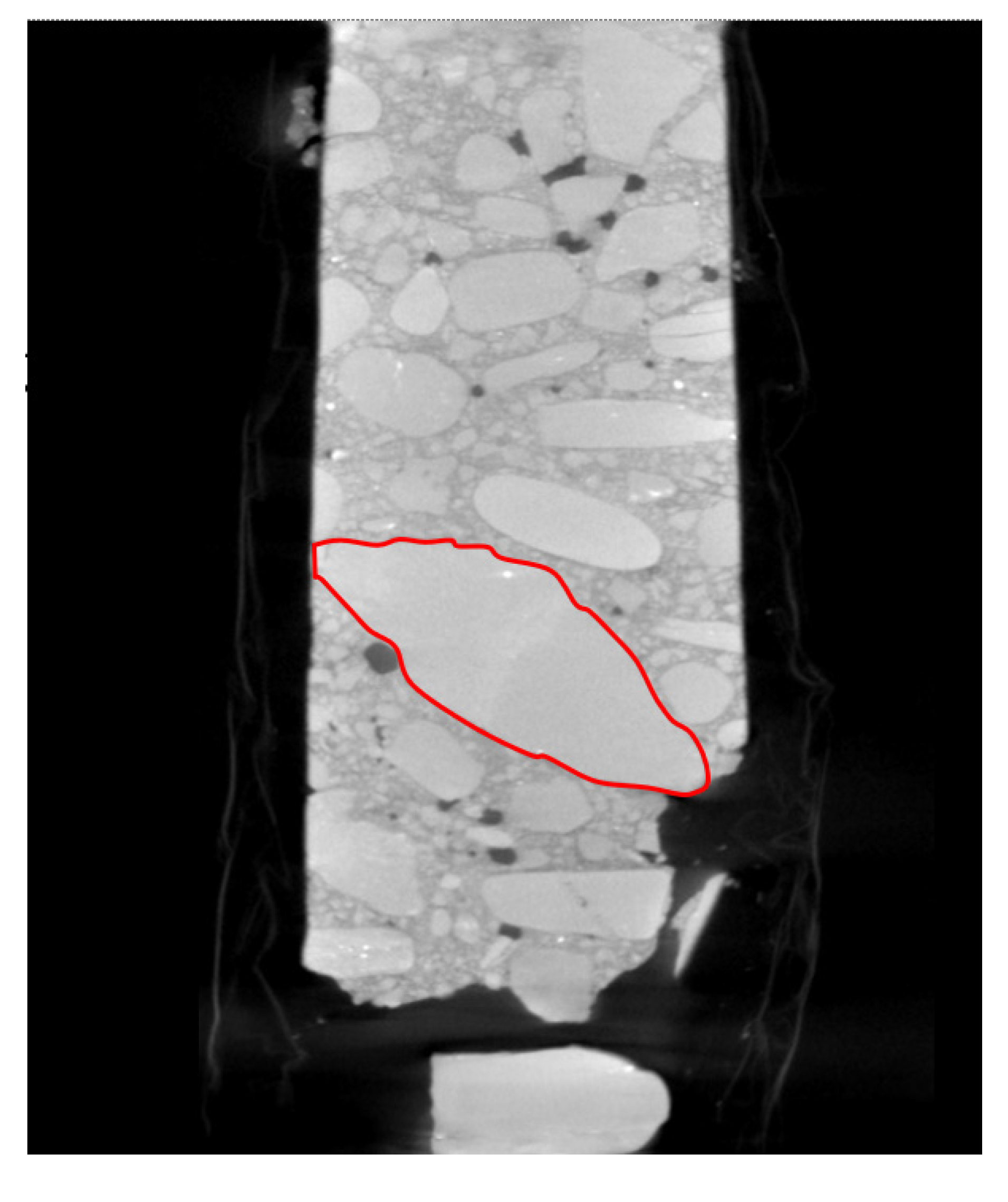
- The four types of cracks can be attributed to the extremely uneven particle size distribution of aggregates. Large particle size distribution accounts for most of the specimens. As shown in Figure 13, the average particle size of the fine aggregate is 1~2 mm, whereas the particle size of the coarse aggregate marked in the figure reaches 53.6 mm. The difference between the two aggregates is significant. According to analysis of the mesostructure of cement concrete combined with the Mohr–Coulomb principle, first, the embedding effect between coarse and fine aggregates cannot be fully exerted. Secondly, the difference in particle size and spatial distribution of aggregates results in differences in the distribution of cement mortar between aggregates; the coarse aggregates have more voids, so more cement mortar is filled, whereas fine aggregates have less cement mortar, which eventually leads to uneven distribution of the bond strength of cement concrete, and cracks are more likely to occur at weak strengths. In particular, at the point where the fine aggregate gathers, type-IV rupture occurs, which leads to the voiding of the cement concrete slab.
- (4)
- In terms of energy, the plastic strain energy required to generate cracks is much greater than that required to generate microcracks. For the same aggregate particles, the energy dissipated in the generation of microcracks may not be enough to penetrate the aggregate, whereas the energy dissipated in the generation of cracks is larger, so it is more likely to cut and penetrate the aggregate particles. In addition, due to its high plastic strain energy, when passing through the area where the fine aggregates are concentrated, the energy causes the fine aggregates to be fragmented in large quantities to form a local fragmentation phenomenon, that is, type-IV cracking.
3. Conclusions
In this study, drilling core sampling was carried out in a project section after microcrack homogenization. The cracks generated by the microcrack homogenization process were classified based on X-ray CT scanning technology. The causes and mechanism were analyzed, and the following conclusions were drawn:
- (1)
- The statistical results of the number of cracks in the core-drilling specimens show that there were 3582 type-I microcracks, 3197 type-II microcracks, and 1835 type-III microcracks, with an average proportion of microcracks of 47.51%. This result shows that the microcrack homogenization process produced a considerable number of microcracks in the test section and achieved a specific crushing effect. However, there were still macrocracks that cannot be ignored. The reason for this might be the relative randomness of the sampling locations and the differences in the structural conditions of the cement pavement before crushing.
- (2)
- The cracks produced by the microcrack homogenization process can be divided into microcracks and macrocracks. Microcracks occur the initial stage of cracking, with cracking resulting from the further development of microcracks. The development laws of the two are similar. Both developed easily along the transition zone of the aggregate–cement mortar interface. However, the energy dissipated by cracking was enormous, and the probability of cutting and penetrating the aggregate was high.
- (3)
- Uneven particle size distribution and needle-like shape of aggregate were the main reasons for cracking. Generating more microcracks and suppressing cracking could achieve a better effect of the microcrack homogenization process. The following measures could be taken in the cement concrete mixture ratio design stage. First, the particle size and ratio of coarse and fine aggregates should be reasonably designed to form a more uniform spatial distribution structure of the aggregates. Secondly, smooth, round aggregates should be used, and the content of needle flake aggregates should be controlled.
- (4)
- To promote the further development of the microcrack homogenization process, it was necessary to achieve refinement at the construction execution level according to the differentiation of the structural conditions of the cement pavement before crushing. First of all, construction personnel should strengthen the preinspection of the original pavement structure before microcrack treatment, such as by using traditional deflection detection or intelligent non-destructive testing methods to detect existing cracks and voids and other diseases in cement concrete pavement. Secondly, for these original “weak areas” of the pavement structure, the initial position of the drop hammer impact can be lowered, and the drop hammer gear can be reduced to achieve refinement.
Author Contributions
Conceptualization, R.W. and H.W.; methodology, Y.L.; software, M.Z.; validation, H.W. and Y.L.; formal analysis, M.Z.; investigation, R.W.; resources, R.W. and C.C.; data curation, H.W. and C.C.; writing—original draft preparation, R.W. and M.Z.; writing—review and editing, H.W. and Y.L.; visualization, M.Z.; supervision, Y.L.; project administration, H.W.; funding acquisition, R.W. All authors have read and agreed to the published version of the manuscript.
Funding
This research was funded by the Fundamental Research Funds for the Central Universities, project no.31920200033; and the Scientific Research Project of Gansu Provincial Traffic Department, project no.2020-03.
Institutional Review Board Statement
Not applicable.
Informed Consent Statement
Not applicable.
Data Availability Statement
Not applicable.
Conflicts of Interest
The authors declare no conflict of interest.
References
- Shu, Q. Brief Analysis on Reconstruction Technology of Cement Concrete Pavement from White to Black. J. Highw. Transp. Res. Dev. 2014, 10, 69–70+82. [Google Scholar]
- Wang, J. Analysis the Control techniques of reflection crack on asphalt overlay of old cement concrete pavement. In Proceedings of the International Conference on Civil, Architectural and Hydraulic Engineering (ICCAHE 2012), Zhangjiajie, China, 10–12 August 2012. [Google Scholar] [CrossRef]
- Pan, S. Application of Resonance Crushing Technology in Cement Concrete Pavement Reconstruction. Transp. World 2022, 11, 73–74. [Google Scholar] [CrossRef]
- Wu, C.; Yuan, J.; Deng, J. On-site crushing and regeneration evaluation of old cement concrete pavement and application of HHT-3 fracturing and compression stabilization. In Proceedings of the 6th China Highway Science and Technology Innovation High-Level Forum (Volume 1), Beijing, China, 17–18 April 2013; pp. 118–123. [Google Scholar]
- Qiu, S. Application of fracturing and stabilizing technology in pavement “white to black” project. Fujian Jiaotong Keji 2019, 5, 35–37. [Google Scholar]
- Li, H.; Yu, H.; Wu, C. Engineering Application of Microcrack Homogenization Treatment and Regeneration Technology for Cement Pavement. In Proceedings of the 8th Annual Academic Conference of Maintenance and Management Branch of China Highway Society, Xiamen, China, 18–19 January 2018; pp. 289–297. [Google Scholar]
- Wu, C.; Fang, D.; Zhang, P. Application of Micro-Crack Regeneration Grouting Reinforcement Technology in the Reconstruction of Old Cement Concrete Pavement; Fujian Jiaotong Keji: Fuzhou, China, 2017; pp. 2–9. [Google Scholar]
- Song, Y. Application effect analysis of micro-crack homogenization treatment of old cement pavement in Hengnan section of National Highway 322 in Hengyang City. Constr. Mater. Decor. 2019, 24, 268–269. [Google Scholar]
- Wang, D. Micro-Crack Homogenization Treatment and Regeneration Technology for Cement Concrete Pavement. Ph.D. Thesis, Chang’an University, Xi’an, China, 2019. [Google Scholar] [CrossRef]
- Zhao, M. Mechanism of Cement Pavement Microcrack Homogenization under Impact of Falling Weight. Ph.D. Thesis, Chang’an University, Xi’an, China, 2021. [Google Scholar] [CrossRef]
- Meng, K.; Liang, B.; Liu, J.; Yan, F. Review on application research of micro computed tomography in the concrete performance analysis in microfocus industry. Miner. Resour. Geol. 2020, 34, 396–400. [Google Scholar] [CrossRef]
- Morgan, I.L.; Ellinger, H.; Klinksiek, R.; Thompson, J.N. Examination of concrete by computerized tomography. J. Am. Concr. Inst. 1980, 77, 23–27. [Google Scholar]
- Lawler, J.S.; Keane, D.T.; Shah, S.P. Measuring three-dimensional damage in concrete under compression. ACI Mater. J. 2001, 98, 465–475. [Google Scholar] [CrossRef]
- Suzuki, T.; Ogata, H.; Takada, R.; Aoki, M.; Ohtsu, M. Use of acoustic emission and X-ray computed tomography for damage evaluation of freeze-thawed concrete. Constr. Build. Mater. 2010, 24, 2347–2352. [Google Scholar] [CrossRef]
- Tian, W.; Dang, F.; Liang, X. CT analysis on dynamic meso-fracture process of concrete based on the image processing. J. Hydroelectr. Power Gener. 2009, 28, 147–151. [Google Scholar]
- Zhou, S.; Liu, J.; Li, B.; Zhang, S.; Liu, T. Numerical Simulation Study of Concrete Microscopic Damage Based on CT Image. China Concr. Cem. Prod. 2022, 29–32. [Google Scholar] [CrossRef]
- Fan, W.; Liu, F.; Xu, J.; Hu, G.; Wang, W.; Wang, Y.; Cheng, W.; Zhou, P.; Sun, H.; Xia, T. Research on Digital Control of Asphalt Pavement Construction Quality Based on CT Technology. Jiangxi Expressway Investment Group Co., Ltd.; Nanchang Engineering College; Jiangxi Transportation Consulting Company; Jiangxi Ex-pressway Investment Group Fuzhou-Jian Expressway Project Construction Office. 2012-01~2015-08. Available online: https://kns.cnki.net/KCMS/detail/detail.aspx?dbname=SNAD&filename=SNAD000001671025.2016 (accessed on 25 April 2022).
- Li, S.; Zhang, H.; Fang, S.; Ma, Y.; Chen, S. Application of CT scan in pavement overlay structure. J. Chang. Univ. Sci. Technol. 2020, 17, 1–6. [Google Scholar]
- Griffith, A.A. The Phenomena of Rupture and Flow in Solids. Philos. Trans. R. Soc. A 1920, A221, 163–198. [Google Scholar] [CrossRef] [Green Version]
- Kaplan, M.F. Crack Propagation and the Fracture of Concrete. J. Proc. 1961, 591–610. [Google Scholar]
- Jenq, Y.; Shah, S.P. A Fracture toughness criterion for concrete. Eng. Fract. Mech. 1985, 21, 1055–1069. [Google Scholar] [CrossRef]
- Jenq, Y.; Shah, S.P. Two Parameter Fracture Model for Concrete. J. Eng. Mech. 1985, 111, 1227–1241. [Google Scholar] [CrossRef]
- Bažant, Z.P.; Oh, B.H. Crack Band Theory for Fracture of Concrete. Mater. Struct. 1983, 16, 155–177. [Google Scholar] [CrossRef] [Green Version]
- Hillerborg, A.; Modéer, M.; Petersson, P.E. Analysis of crack formation and crack growth in concrete by means of fracture. Cem. Concr. Res. 1976, 6, 773–782. [Google Scholar] [CrossRef]
- Dougill, J.W.; Bažant, Z.P. Constitutive relations for concrete and rock: Applications and extensions of elasticity and plasticity theory. In Mechanics of Geomaterials: Rocks, Concrete, Soils; Dougill, J.W., Ed.; John Wiley & Sons: Chichester, UK, 1985; pp. 21–46, (papers to the IUTAM William Prager Symposium, Evanston, 11–15 Sept 1983) P2. International Journal of Rock Mechanics and Mining Sciences & Geomechanics Abstracts, 1986, 23, 175; Available online: https://www.researchgate.net/publication/282992304_constitutive_relations_for_concrete_and_rock_applications_and_extensions_of_elasticity_and_plasticity_theory (accessed on 25 April 2022).
- Krajcinovic, D. Constitutive Equations for Damaging Materials. J. Appl. Mech. 1983, 50, 355. [Google Scholar] [CrossRef]
- Li, J. Research on the Stochastic Damage Mechanics for Concrete Materials and Structures. J. Tongji Univ. Nat. Sci. 2004, 32, 1270–1277. [Google Scholar]
- Zhou, Z. Principle of least rate of energy consumption and some application of its in solid mechanics. Nat. Sci. J. Xiangtan Univ. 1993, 41–47. [Google Scholar]
- Tang, S.; Luo, Y.; Zhou, Z. Establishing the damage developing equation of concrete through the principle of minimum dissipation of energy. J. Jinan Univ. Nat. Sci. Med. Ed. 2005, 26, 69–71. [Google Scholar]
- Wang, H. Study on Elastic-Plastic Constitutive Based on the Least Energy Dissipation Principle and Numerical Simulation of Crack Propagation. Ph.D. Thesis, Jinan University, Guangzhou, China, 2012. [Google Scholar]
- Wittmann, F. Fracture toughness and fracture energy of concrete. In Proceedings of the International Conference on Fracture Mechanics of Concrete, Lausanne, Switzerland, 1–3 October 1985. [Google Scholar]
- Zampini, D.; Shah, S.P.; Jennings, H.M. Early age microstructure of the paste-aggregate interface and its evolution. J. Mater. Res. 1998, 13, 1888–1898. [Google Scholar] [CrossRef]
- Yao, C. Fatigue Damage and Life Prediction of Concrete. Ph.D. Thesis, Harbin Institute of Technology, Harbin, China, 2010. Available online: http://lib.xbmu.edu.cn/asset/detail/0/20429075326.2010 (accessed on 25 April 2022).
- Mei Tai, P.K. Structure, Properties and Materials of Concrete, Tongji University Press: Shanghai, China, 1991.
- Li, Z. Damage Mechanics and Its Applications, 2002. Available online: https://book.sciencereading.cn/shop/book/Booksimple/show.do?id=B3CF6C62B01D7412C9A8E598BCAE24752000 (accessed on 25 April 2022).
- Shang, Y. Numerical Simulation of Static and Dynamic Mechanics Performance of Mas Concrete. Ph.D. Thesis, Hohai University, Nanjing, China, 2004. [Google Scholar]
Figure 1.
X-ray CT scan image.
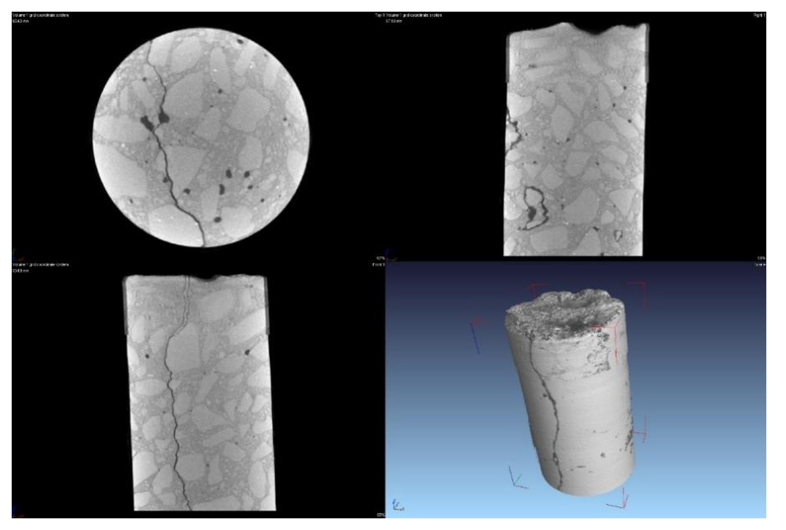
Figure 2.
The X-ray CT scanning room.

Figure 3.
Schematic diagram of cracks, voids, and sandstone.

Figure 4.
Type-I microcrack.

Figure 5.
Type-II microcrack.
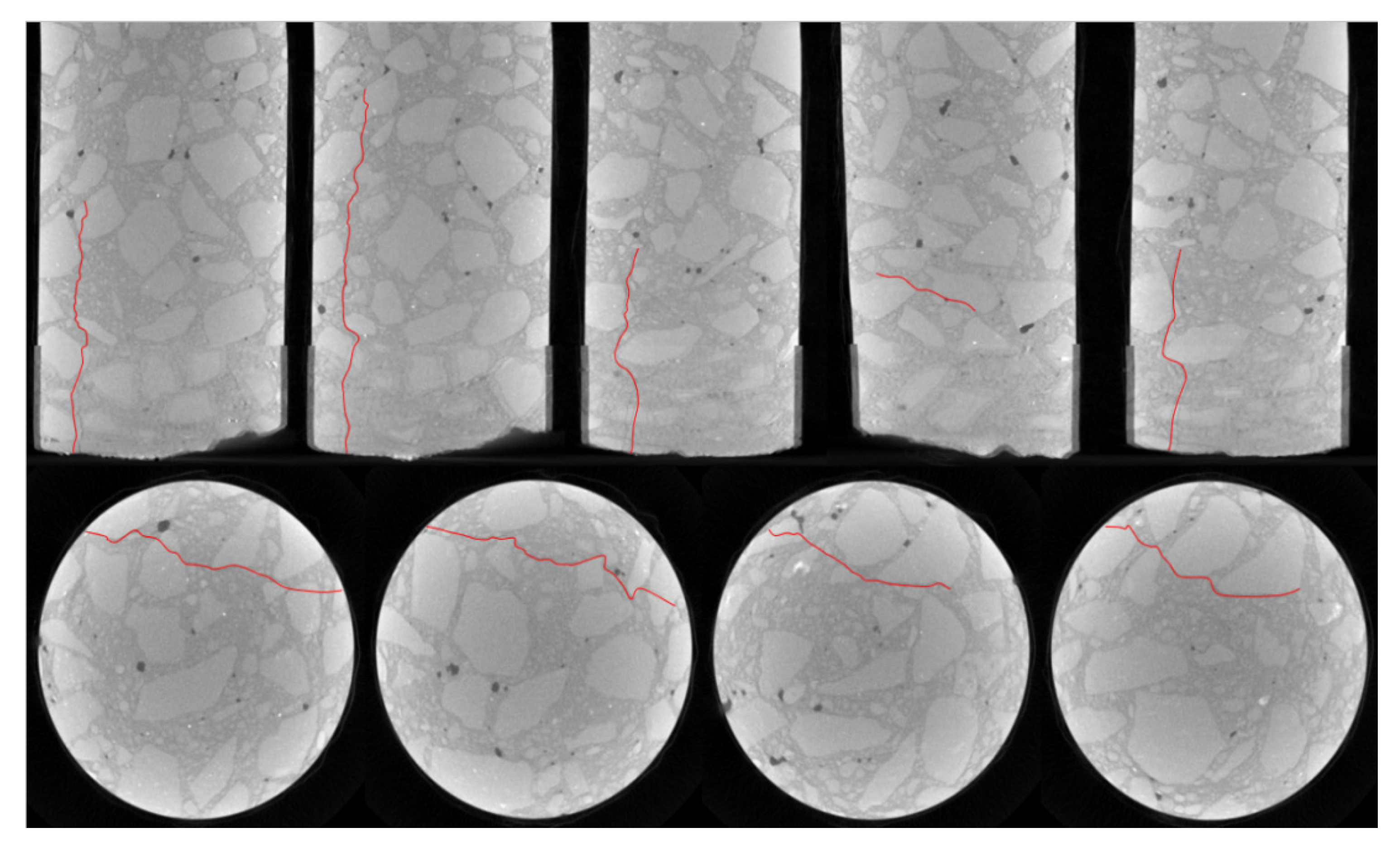
Figure 6.
Type-III microcrack.
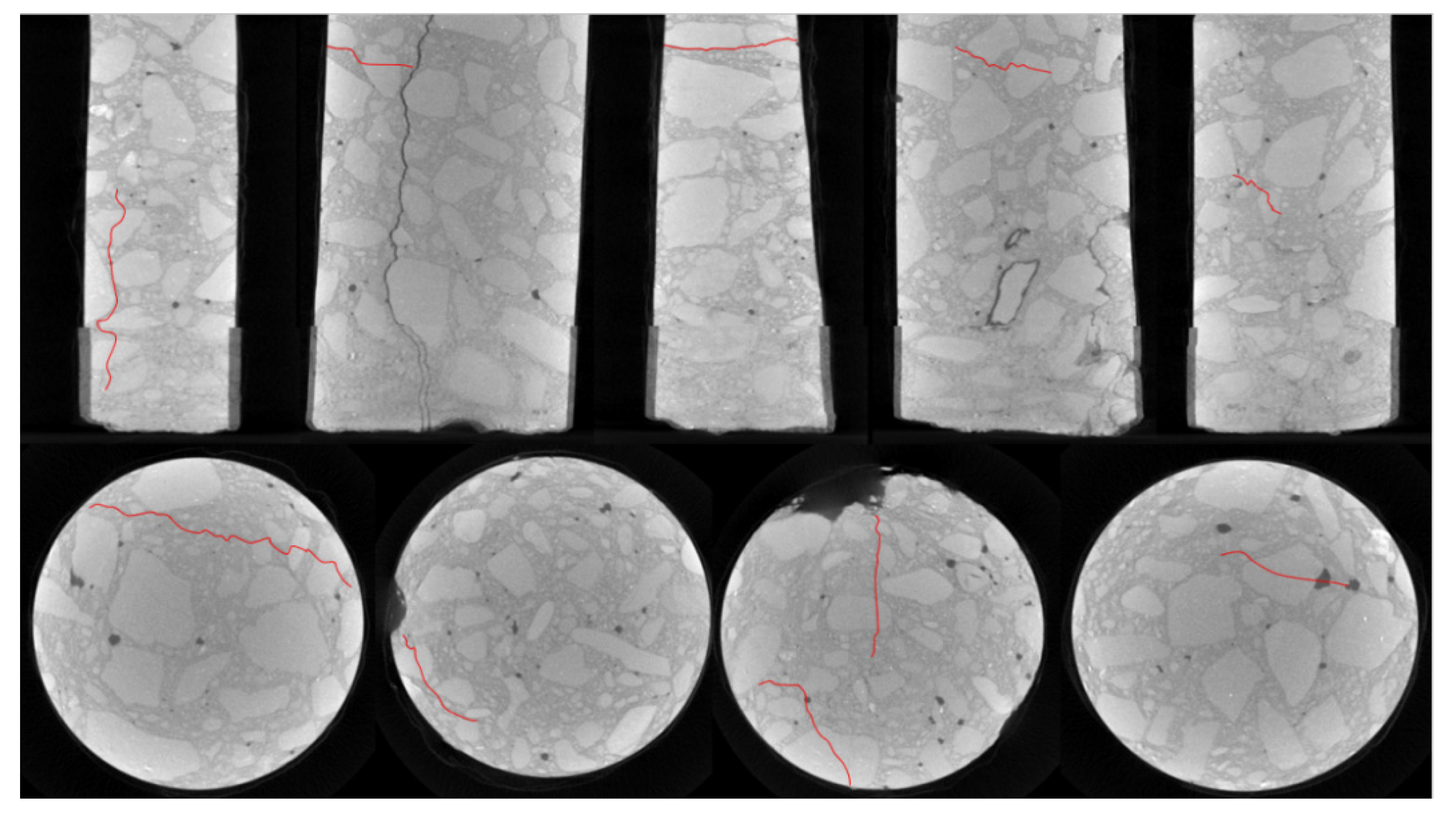
Figure 7.
Type-I crack.
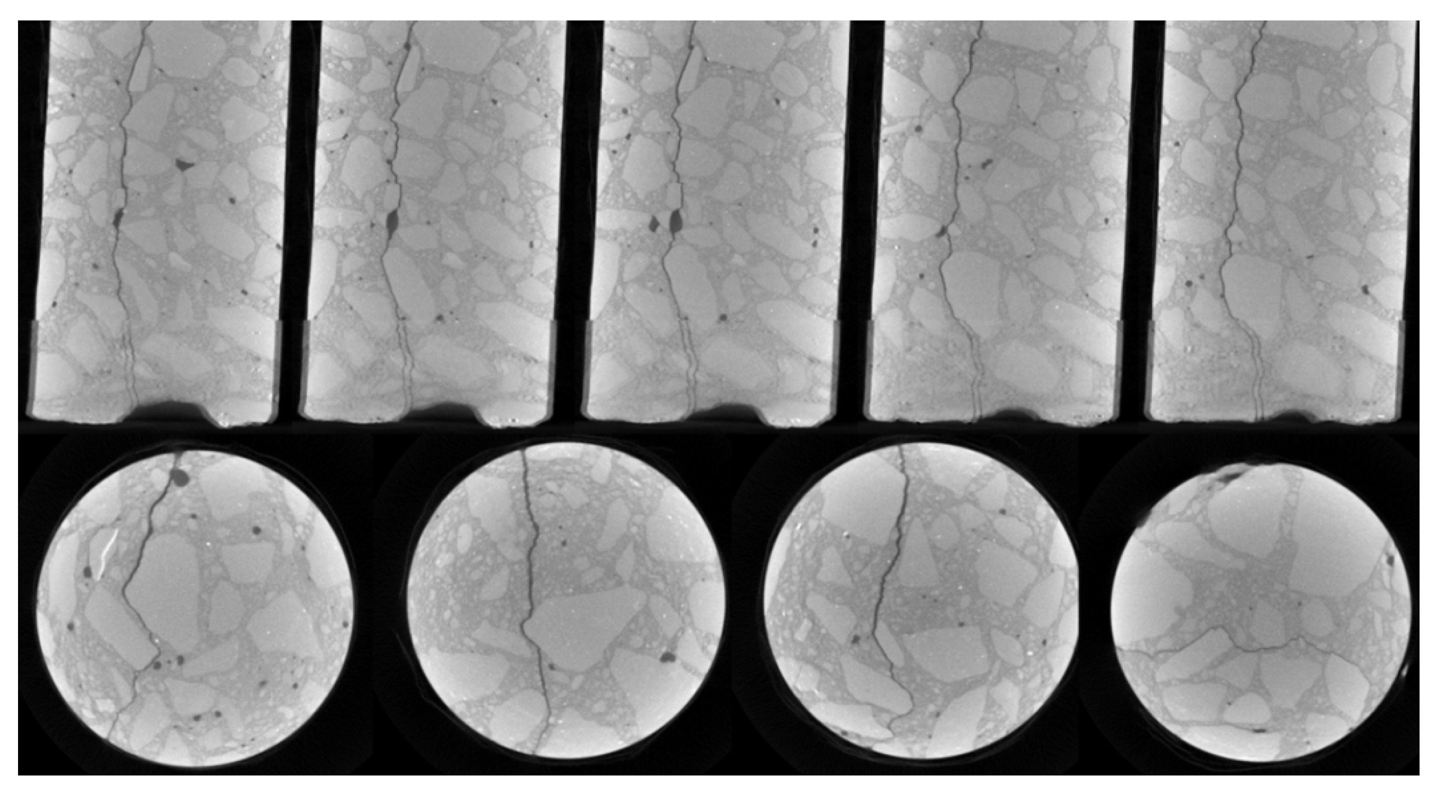
Figure 8.
Type-II crack.
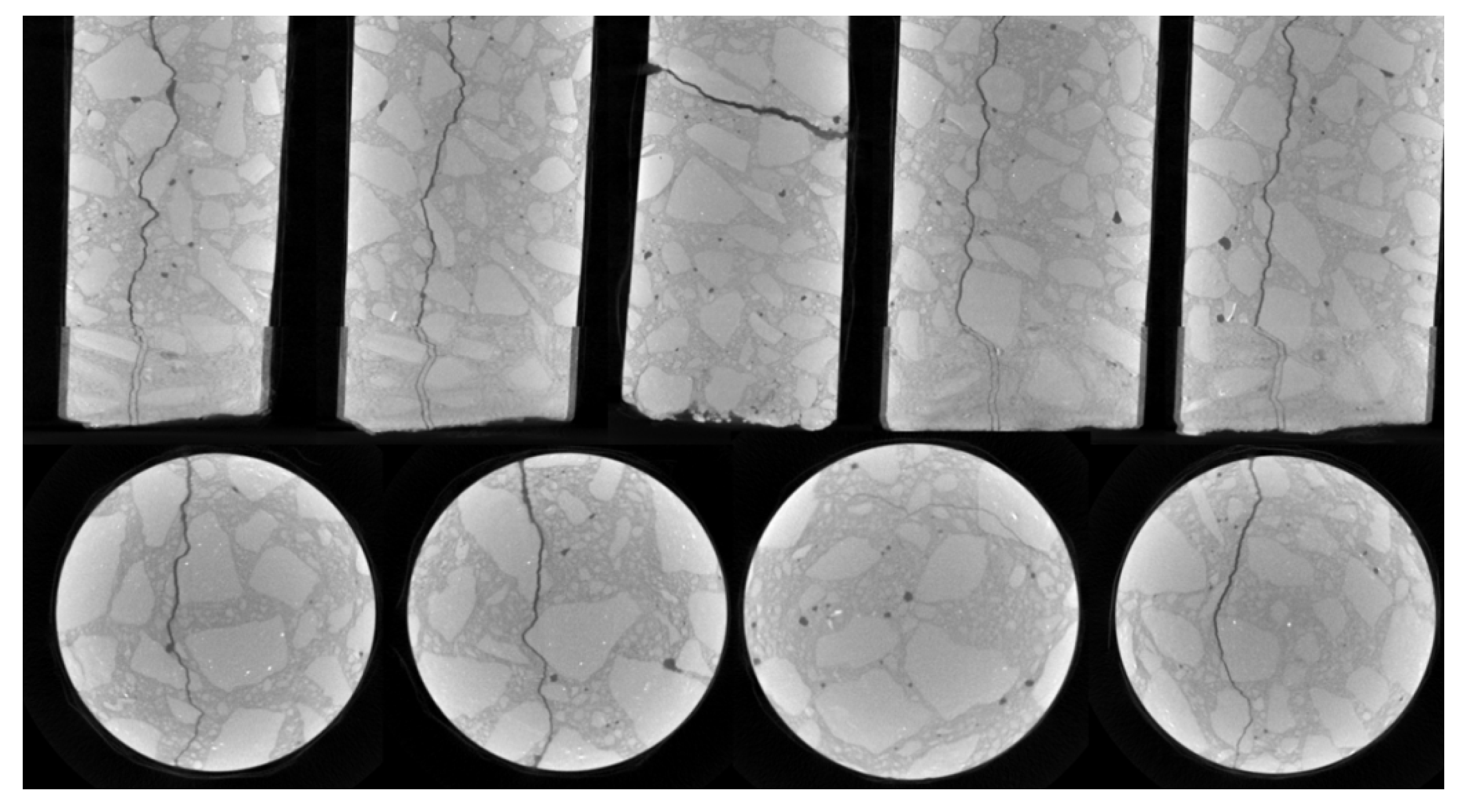
Figure 9.
Type-III crack.
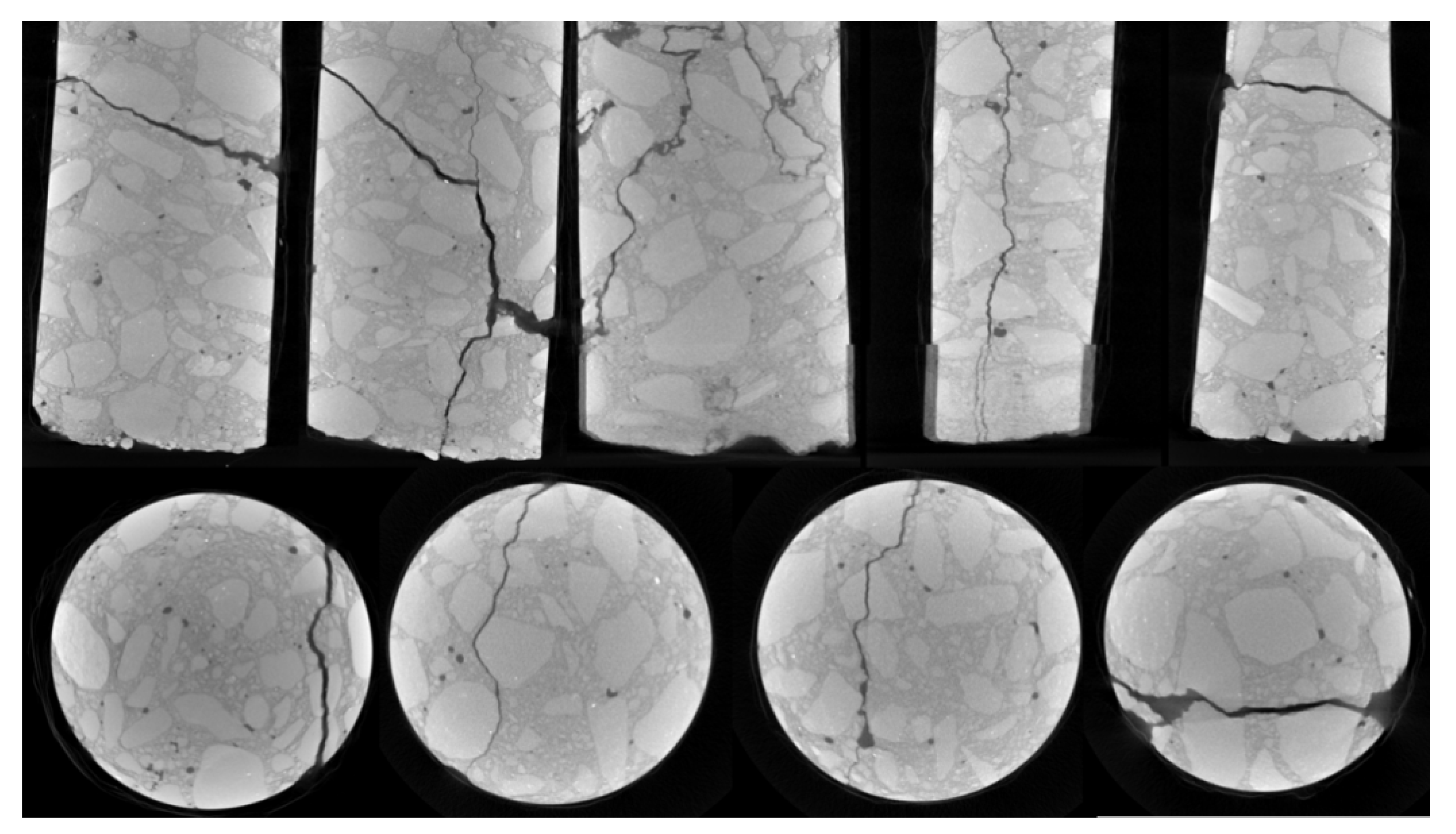
Figure 10.
Type-IV crack.
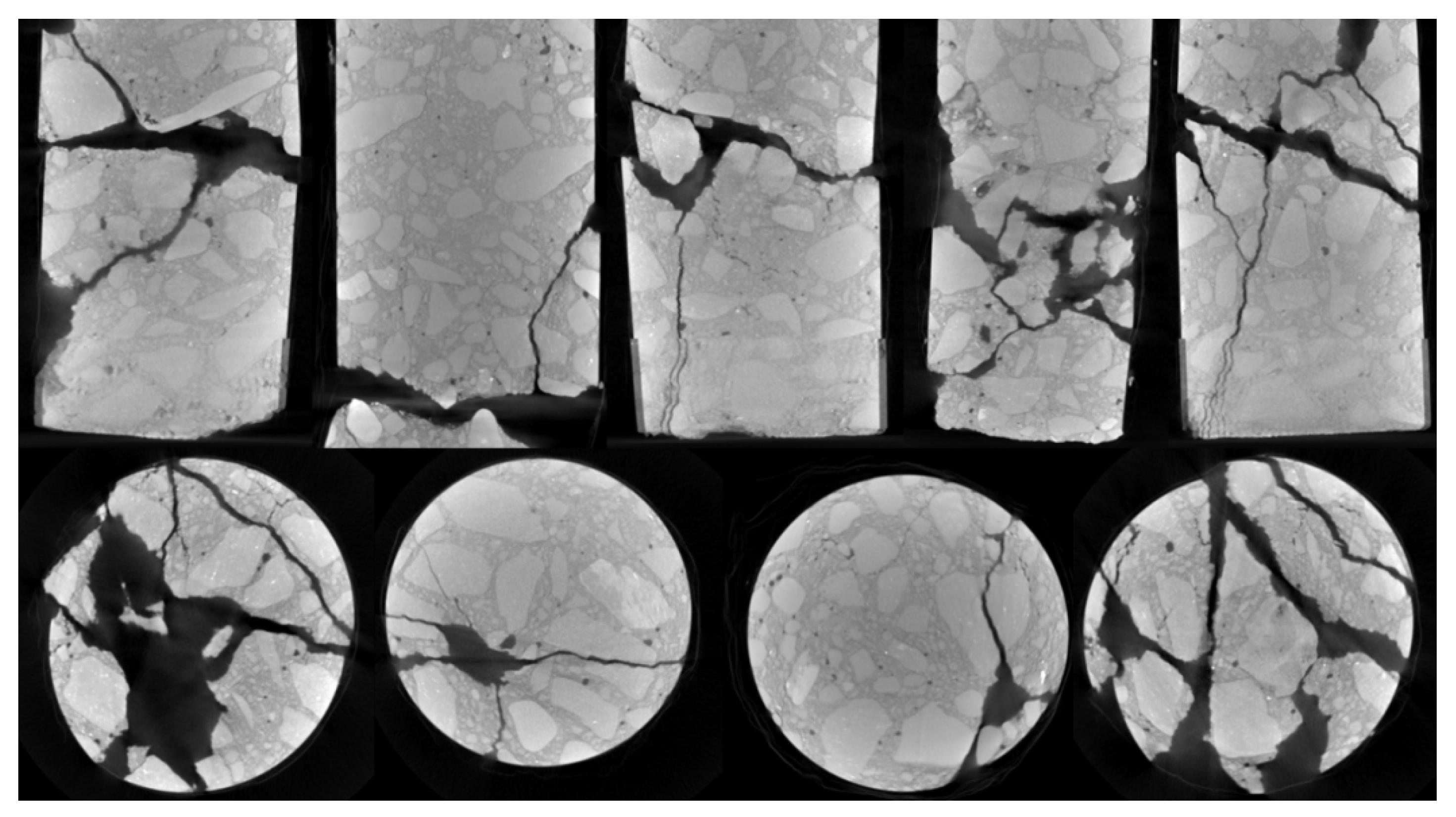
Figure 11.
Spherical aggregates (left) and needle-like aggregates (right).

Figure 12.
Uneven spatial distribution of coarse and fine aggregates.

Figure 13.
Uneven particle size distribution of coarse and fine aggregates.

Table 1.
Crack classification.
| Type | Characteristics |
|---|---|
| Type-I microcrack | The cracks developed completely along the outline of the coarse aggregates. |
| Type-II microcrack | The cracks developed along the outline of the coarse aggregates, but there was a phenomenon whereby the bangs cut through the corners of the coarse aggregates. |
| Type-III microcrack | The cracks developed along the outline of the coarse aggregates, but there was a phenomenon whereby the crack cut through the center of the coarse aggregates. |
| Type-I crack | The development direction of the crack was entirely along the outline of the coarse aggregates, and the cracks were relatively slender. |
| Type-II crack | The development direction of the cracks was basically along the outline of the coarse aggregate, but there was a phenomenon whereby the cracks cut through the corner of the coarse aggregate, and the cracks were relatively slender. |
| Type-III crack | The development direction of the cracks was not completely along the outline of the coarse aggregates; the cracks directly cut through the center of the coarse aggregate, and the cracks were thicker. |
| Type-IV crack | The crack development followed the outline of the coarse aggregates, causing fragmentation in the area where the fine aggregates gathered. The fragmentation was strip-shaped or block-shaped to a large extent. |
Table 2.
The number of cracks.
| Project Road Section Number | CT Slice Images (Sheets) | Type-I Microcracks (Strips) | Type-II Microcracks (Strips) | Type-III Microcracks (Strips) | Type-I Cracks (Strips) | Type-II Cracks (Strips) | Type-III Cracks (Strips) | Type-IV Cracks (Strips) | Microcrack Ratio (%) |
|---|---|---|---|---|---|---|---|---|---|
| K4+950−1 | 841 | 517 | 640 | 323 | 170 | 20 | 428 | 841 | 50.36 |
| K4+950−2 | 861 | 584 | 369 | 275 | 647 | 452 | 548 | 861 | 32.87 |
| K5+000 | 795 | 676 | 399 | 227 | 844 | 357 | 469 | 795 | 34.56 |
| K6+000 | 772 | 218 | 146 | 24 | 0 | 0 | 0 | 0 | 100.00 |
| K8+100 | 784 | 578 | 683 | 396 | 589 | 214 | 134 | 0 | 63.88 |
| K8+200 | 769 | 324 | 448 | 165 | 213 | 285 | 106 | 0 | 60.80 |
| K8+300 | 829 | 685 | 512 | 425 | 459 | 387 | 327 | 371 | 51.23 |
| Total | 5651 | 3582 | 3197 | 1835 | 2922 | 1715 | 2012 | 2868 | 47.51 |
Publisher’s Note: MDPI stays neutral with regard to jurisdictional claims in published maps and institutional affiliations. |
© 2022 by the authors. Licensee MDPI, Basel, Switzerland. This article is an open access article distributed under the terms and conditions of the Creative Commons Attribution (CC BY) license (https://creativecommons.org/licenses/by/4.0/).
Share and Cite
MDPI and ACS Style
Wang, R.; Wu, H.; Zhao, M.; Liu, Y.; Chen, C. The Classification and Mechanism of Microcrack Homogenization Research in Cement Concrete Based on X-ray CT. Buildings 2022, 12, 1011. https://doi.org/10.3390/buildings12071011
AMA Style
Wang R, Wu H, Zhao M, Liu Y, Chen C. The Classification and Mechanism of Microcrack Homogenization Research in Cement Concrete Based on X-ray CT. Buildings. 2022; 12(7):1011. https://doi.org/10.3390/buildings12071011
Chicago/Turabian StyleWang, Rui, Hongjuan Wu, Mohan Zhao, Yu Liu, and Chengqin Chen. 2022. "The Classification and Mechanism of Microcrack Homogenization Research in Cement Concrete Based on X-ray CT" Buildings 12, no. 7: 1011. https://doi.org/10.3390/buildings12071011
Note that from the first issue of 2016, this journal uses article numbers instead of page numbers. See further details here.