
Lightweight Composite Partitions with High Sound Insulation in Hotel Interior Spaces: Design and Application

Key Laboratory of Urban and Architectural Heritage Conservation, Ministry of Education, School of Architecture, Southeast University, 2 Sipailou, Nanjing 210096, China
*
Author to whom correspondence should be addressed.
Buildings 2022, 12(12), 2184; https://doi.org/10.3390/buildings12122184
Submission received: 9 November 2022
/
Revised: 28 November 2022
/
Accepted: 5 December 2022
/
Published: 9 December 2022
(This article belongs to the Special Issue Indoor Environmental Quality and Occupant Comfort)
Abstract
:Sound insulation performance of partitions is one of the key factors contributing to the comfort of the hotel interior spaces. Based on the theory of constrained layer damping, this study proposed the light-weight composite partition structure with high sound insulation, which was composed of gypsum boards of different thicknesses and an isobutylene isoprene rubber board. The normal incidence sound transmission loss of the structure was evaluated through finite element simulations as well as experiments, which were conducted in a standing wave tube. The results show that the simulation and experimental results of two kinds of lightweight high sound insulation multi-layer composite partition walls are closely aligned; the surface density of the optimized partition wall was less than 42 kg/m2, although the normal incidence STL exceeded 51.8 dB at 200 Hz and at 1/3 octave of 1000 Hz with the maximum value of 58.5 dB. The lightweight composite partition wall with high sound insulation has a huge application potential in enhancing the sound environment quality of hotels.
1. Introduction
Sound insulation performance of the partition wall is one of the important indicators to measure the comfort of the hotel room environment, since high-quality sound environment can bring a pleasant experience for the residents [1]. Meanwhile, the sound insulation performance of the partition wall is a key factor of indoor environment quality (IEQ) [2,3,4]. It is worth mentioning that the lightweight partition wall has become one of the important considerations in building designing, due to the increasingly high requirements in lightweight design for green and energy-saving buildings. However, lightweight partitions usually have poor sound insulation performance according to the mass law.
Therefore, to address the contradiction between the low sound insulation performance of partition walls and higher IEQ requirements, many researchers have studied the sound insulation performance of lightweight partition walls from various perspectives [5]: the material types, surface density, and thickness [6]. Hagberg et al. used artificial neural networks, evaluating the acoustic performance of the sound insulation curves of different lightweight wood flooring materials, and acoustic data and subjective evaluation, examining the acoustic comfort of residential buildings [7,8,9,10]. Since the sound insulation is closely related to the material parameters of the composite structure layered panel, it can suppress the resonance effect of low frequency and the coincidence effect of high frequency.
Adding the viscoelastic material (VEM) core to the lightweight partition wall can effectively improve the sound insulation performance, because the VEM core is directly affected by the relative in-plane displacement of the constrained layer and the base layer, and the constrained layered damping (CLD) composite structure has a stronger energy dissipation ability than the free damping composite structure [11,12]. Quite a number of studies focused on the application of VEM in reducing the vibration of mechanical structures, however, few were on the sound insulation. Jung et al. [13,14] obtained the vibration isolation effect in a wide frequency range by periodically inserting VEM structures into the engine mounting system, using the finite element method and transfer matrix method in the theoretical analysis model. Gupta et al. [15] studied the free vibration of a damped stiffened sheet and periodically damped plates through the finite element numerical simulation. Zhou et al. [16] designed a new structure in which the VEM was inserted between two stiffeners, and found that the VEM had a significant impact on the vibration of the deflection and the propagation characteristics of low-frequency vibration energy.
To improve the sound transmission loss (STL) of composite structures, Moore et al. [17,18,19,20,21] proposed a new wall design with three interlayers, and found that when the Young’s modulus of the panel was greater than that of the core material, the shear wave velocity increased with the thickness of the core material; when the damping loss factor was equal to that of the core material, the sound insulation performance of the plate was the worst. Thamburaj et al. [20] studied the acoustic and vibration transmission of sandwich beams with special materials, and found that the STL can be significantly increased through optimizing different damping, thickness, mass density and isotropic or anisotropic surface layer materials, and changing Young’s modulus and shear modulus parameters [20]. Varanasi et al. [22,23,24,25] proposed that the orthogonal anisotropic materials were embedded in the composite structure as core layers. In addition, some researchers analyzed the STL and the three-dimensional vibration of composite structural plates [26,27,28], showing that the sensitivity of thin plate to material properties was slightly higher than that of thick plate, and the difference in high frequency region was caused by material damping.
Different core material parameters and sound insulation rules also play important roles in the STL of composite structure partition [29]. Kurtze and Watters [30,31,32] analyzed the sound insulation rules of sandwich plates with different composite materials and proposed that moving the coincidence frequency to a frequency higher than a given value could maximize the STL of sandwich plates with fixed mass. Through analyzing various characteristics of the plate, Nilsson A.C. [33] proposed that the acoustic characteristics of the sandwich plate could be self-optimized within the frequency range set. Niu et al. [34] proposed the discrete material optimization method for the design of fiber angle layer and the sequence selection of composite materials. Bouzouane et al. [35,36,37] studied the layered material parameters of sandwich plate and sandwich beam, and found that the thickness of VEM core greatly influenced the acoustic and vibration characteristics, and the values of STL increased with the core material thickness; for sandwich beams, the apparent bending stiffness is related not only to material parameters, but also frequency, boundary conditions and beam length parameters.
Some researchers have studied the numerical value and prediction method of the sound insulation performance of CLD sandwich structures. Assaf S. et al. [38] proposed an optimized damping sandwich structure using a set of high STL prediction methods. Santoni et al. [39] proposed a prediction model for the radiation effect of orthotropic plates using different methods, which considered the resonant and non-resonant contributions of each mode and the fluid loading effect on the sound radiation property of the plate. Guyader et al. [40,41] established the motion equation and natural boundary conditions of multilayer plates by using the dynamic equations, verified the continuity of displacement and shear stress at the interface, proposed the expression of transfer loss of viscoelastic orthogonal anisotropic finite multilayer plates, and proposed the influence on its main parameters. Huang et al. [42] developed an analytical theory of STL and reflected the unbounded plates composed of functionally gradient materials. Kang et al. [43] proposed a method to determine the critical apparent bending stiffness of sandwich plates. Howson et al. [44] proposed a method to determine the single and sandwich beam converging to any fixed frequency by a high-precision method to replace the traditional finite element technique. Backstrom et al. [45] deduced a sixth-order model that was in good agreement with the measured data within the frequency band of interest.
A large number of researchers have studied the application of high sound insulation composite plates from mechanical engineering in the electronics industry. However, few took the application perspective in studying the building space partition. The current study aimed to combine VEM and CLD in researching and designing the internal partition walls, so as to effectively improve the sound environment of the building space.
The current study examined the effects of four parameters (i.e., the material types, the surface density, the number of the VEM core, and the Young’s modulus) on the sound insulation performance. This paper reporting the study is structured as follows: Section 2 gives the theoretical method of designing a single-layer plate and a double-layer composite structure; Section 3 presents the finite element method used for the numerical simulation and the analysis of the parameters of layers and core layers with different thicknesses, and discusses the influence of parameter setting on sound insulation performance and proposes an optimized structure; Section 4 presents the simulation and experimental results of the single-layer plate, which verified the feasibility of the method, and discusses the influence of the parameter-setting of surface layer and core layer on STL through comparing the simulation and experimental results of optimized configuration; Section 5 draws the conclusion.
2. Theory Analysis
2.1. Simulation of Single Layer Partition
Since the STL would increase with the increase in frequency, when the surface density of a single wall is constant, and the sound insulation performance of a single-layer homogeneous partition wall is affected by resonance and coincidence effect [46], as well as damping and stiffness, the sound insulation characteristic curve of a single-layer homogeneous partition wall is divided into three control zones according to frequency: stiffness control zone, mass law control zone, and (coincidence region [47], as shown in Figure 1.
Stiffness controlled zone (Area I): since each wall has its inherent natural resonance frequency range, the wall resonates when the external sound frequency is equal to the inherent frequency of the wall. In the area I, the sound insulation capacity of the single-layer partition is inversely proportional to the growth rate of the frequency, that is, the sound insulation capacity of the partition decreases by 6 dB with the increase in octave band frequency. With the increase in frequency, the wall enters the resonance region, and the natural frequency of the partition resonates with the frequency of the incident sound wave. In addition, the most influential is the first resonant frequency (f0) within the range of 700 Hz~1500 Hz as in Figure 1, though there are many resonant frequencies in the resonance region. In the design process, therefore, the resonant frequency region should be narrowed as much as possible to exclude the first resonant frequency from the interesting frequency range.
Mass-law controlled zone (Area II): Figure 1 shows that the damping is positively related to the inhibition effect on the amplitude of resonance. As the frequency of incident sound wave increases, the resonance phenomenon disappears in the mass control area (Area II), where the STL is controlled by the mass law.
Damping controlled zone (Area III): When the frequency continues to increase across the mass control area, the sound insulation trough, called “coincidence region”, occurs, when the mass effect and the bending stiffness effect of the partition wall cancel out. The sound insulation performance of the partition wall is affected by the coincidence effect (Area Ⅲ), where the structural vibration mode is increasingly intense. However, due to the damping and internal friction of the partition wall, the vibration of the partition wall may or may not increase. As Figure 1 shows, the damping of the partition is negatively related to the vibration amplitude, which causes the less obvious coincidence valley.
2.2. Sound Insulation Theory of Multilayer Composite Partition
Based on the Kelvin-Voigt model of the constrained damping composite structure, a constitutive model was established, describing the Young’s modulus, loss modulus, loss factor, storage modules, surface density, and relaxation time of the structure. Combined with the acoustic equation, a theoretical calculation method of STL was obtained.
Assuming that the composite plate is infinite in the XY direction of the coordinate system shown in Figure 2, the space on both sides is air medium, the incident acoustic wave is plane simple harmonic, the perpendicular line of the wave front is in the XZ plane, and the Angle between the wave front and the Z axis is , the acoustic wave equation has the two-dimensional form. The circular frequency of the incident sound wave is ω, the speed of sound in the air is , and the x and z components of the acoustics wave vector are
The acoustic field in the air satisfies the Helmholtz equation:
where φ is the velocity potential function of the sound field. This is referred to as and the sound pressure as , so the relationship between , and is
The potential function in Equation (3) can be expressed as
Composite panels total thickness of , integrating Equation (6) into Equation (3) can derive:
Fantasy Equation (7) into Equations (4) and (5), to obtain the incoming air pipe and transmission particle velocity and pressure, the incoming pipe subscript for , transmission pipe subscript :
In the formula, A, B and C are the coefficients of sound pressure of incident sound, reflected sound and transmitted sound, respectively.
The relationship between the vibration dispositions of any elastic or viscoelastic layer of the composite plate under the action of the sound field and the potential functions of expansion and contraction waves and shear waves can be described by Navier equation:
The potential functions φ and ψ satisfy the wave equation
The sound transmission coefficient of the composite plate is expressed as
Thus, the STL can be written as
3. Simulation and Experiment Setup
3.1. Configuration Design for Composite Partition
The sound insulation effect of a traditional single lightweight partition wall is weak, and could not reach the requirements of the standard value of 45 dB [48]. To overcome these shortcomings, the key parameters affecting sound insulation performance were studied. Thus, the thin and high sound insulation damping composite structure partition walls were proposed. Considering the general specification of the elastic panel and indoor partition in the market, gypsum boards were adopted for designing the partition configuration. The setting range of Young’s modulus, thickness and surface density were 1600–3000 Mpa, 9.5–15 mm, and 600–1200 kg/m3, respectively. The total thickness of CLD composite structure was within 80 mm, with the total surface density less than 50 kg/m2. The VEM core was set to be 1–5 mm thick.
The configuration design process adopted in this study is as follows. Firstly, one typical configuration of the damping composite structure partition walls was established. The panel was composed of two gypsum boards as the surface layer and one VEM core layer with the same thickness. The Young’s modulus, density, thickness of surface layer and VEM core were 1600 Mpa, 600 kg/m3, 9.5 mm and 1 mm, respectively. Secondly, the sound insulation performance of the panel was compared with that of single layer gypsum board. Thirdly, the rules of improving sound insulation performance were established and the structure was further optimized. Table 1 shows the specifications and types in simulation.
3.2. Simulation Models
The COMSOL Multiphysics software was used for the finite element modeling, in which a single physical field or a couple of physical fields can be selected according to the actual needs [49]. The acoustic module of the software was used to analyze the propagation process of acoustic waves, based on the signals of frequency domain and time domain. Since different acoustic interfaces need different physical fields, the model in this study mainly used the pressure acoustics and solid mechanics physical fields to model the configuration, and simulated the variation of STL under the normal sound waves incidence. As shown in Table 1, plasterboards and butyl rubber inserts with different thicknesses were combined in different forms to establish a 1:1 model in COMSOL. The STL simulation of configuration was carried out through the processes of model designing, geometric modeling, parameter setting, solution loading and simulation result processing.
3.3. Experimental Settings
The normal incidence STL experiments were conducted in a semi-anechoic chamber. Based on the Chinese standard of Acoustics-Determination of sound transmission loss in impendence tubes Transfer matrix method (GB/Z 22764-2011) and the American standard Test Method for Measurement of Normal Incidence Sound Transmission of Acoustical Materials Based on the Transfer Matrix Method (ASTM E2611-09) [50,51], the four-microphone transfer matrix method was utilized with a rectangular standing wave tube. Figure 3 shows the block diagram of the experimental measurement system, in which the parameters met the measurement standards, the wall body was an acrylic plate with a thickness of 15 mm, the cross-section size was 100 mm × 100 mm, and the cut-off frequency was 1700 Hz. Thus, the 1/3 octave frequency range between 50 and 1600 Hz was selected. Four G.R.A.S 40AP 1/2-inch sound pressure field microphones were used to measure the sound pressure signals on the inner wall of the tube at a distance of 5 cm from the center points. The specimen was tightened in the middle of the experiment device, and between the four microphones. The HIVI-M3S’s 3.5-inch speakers were powered by an amplifier from the B&K 2716, which was mounted on top of the standing-wave tube and effectively sealed to the inner wall of the tube. In the experiment, the B&K Pulse 3560D system was used to send out sweep signals and carry out the real-time signal acquisition and analysis. Figure 3b is the field measurement diagram.
4. Results and Discussion
4.1. Insulation Performance of the Base Case
This study used the 12 mm single-layer gypsum board as an example to carry out the simulation and compared the simulation results with the experimental results. It was found that due to the single-layer gypsum board effect, the simulation curve of sound insulation frequency had resonance phenomenon and resonance valley between 1200 Hz and 1300 Hz, resulting in a sharp decline in sound insulation performance. However, the simulation results fit well with the experimental results, which verifies the reliability of the theoretical method, as shown in Figure 4.
Compared with the single layer board, the thickness of the single board in Case 1 was thicker, doubled to 25 mm. The sound insulation curve of Case 1 flattened the resonance valley of the single board and increased the single board by more than 10 dB, which greatly improved the STL. It can be seen that the improvement of sound insulation was not only related to the mass law, but also closely related to the VEM core layer, and the constrained layer damping formed a sandwich structure, which changed the frequency of the resonant mode and effectively improved the sound insulation performance. It can also be found that the sound insulation of sandwich partitions was better than that of the single-layer plate. Based on these results, the simulation of Young’s modulus, thickness, density and VEM core thickness of the elastic panel and the combination modes of these parameters were expanded for revealing the influence of parameters more clearly.
4.2. Elastic Panel Parameters Discussed
This part mainly discusses the influence of the variation of Young’s modulus, thickness and density parameters on the sound insulation performance of sandwich structure. Meanwhile, the parameters of Young’s modulus at 2000 Mpa, thickness of 20 mm and density of 600 kg/m3 were selected for experimental verification, which proved the validity of the simulation results.
4.2.1. Influence of Young’s Modulus
Based on Case 1 (basic configuration), the influence of Young’s modulus of sandwich plate was analyzed. When the thickness and density are unchanged, the ranges of Young’s modulus were set at 1600 Mpa, 2000 Mpa and 3000 Mpa, and the thickness of elastic panels and core layer on both sides remained unchanged. Figure 5 shows that in the stiffness control region, with the increase in Young’s modulus, the first resonance frequency moved to high frequency, and the STL significantly increased. In the mass low control area, the STL curve decreased slightly with the increase in Young’s modulus, but the overall sound insulation performance increased steadily.
4.2.2. Influence of Gypsum Board’s Thickness
Based on Case 1 (basic configuration), the influence of sandwich plate thickness was analyzed. When Young’s modulus and density remained unchanged, the thickness ranges of elastic surface layer were set at 9.5 mm, 12 mm and 15 mm. Figure 6 shows that in the stiffness control region, the first-order resonance frequency moved to the high frequency with the increase in the elastic surface layer’s thickness, and the STL significantly increased. In the mass law control area, the STL of sandwich structure increased with the increase in thickness.
4.2.3. Influence of Density
Based on Case 1 (basic configuration), the influence of sandwich plate’s density was analyzed. When Young’s modulus and thickness remained unchanged, the density ranges of elastic surface layer were set at 600 kg/m3, 800 kg/m3, 1000 kg/m3 and 1200 kg/m3. Figure 7 shows that in the first-order stiffness region, the resonance valley moved to high frequency with the increase in density, and the overall STL increased to a certain extent. In the mass law control area, the sound insulation performance was significantly improved with the increase in density value.
4.3. Influence of the VEM Core’s Thickness
Based on Case 1 (basic configuration), the influence of VEM core thickness of sandwich structure was analyzed. When Young’s modulus and density were unchanged, the ranges of VEM core thickness were set at 1 mm, 3 mm and 5 mm. Meanwhile, a splint configuration with VEM core layer thickness of 1 mm was selected to verify the validity of the simulation results. Figure 8 shows that in the first-order stiffness control area, with the increase in VEM core layer’s thickness, the resonance valley tended to be smooth and moved to high frequency, and the sound insulation performance was significantly improved. When the thickness of the core layer was 5 mm, the sound insulation of the first-order resonance valley can be improved by about 6 dB. In the mass law control area, the sound insulation performance of STL curve was also improved with the increase in thickness.
4.4. Influence of Composite Partition Walls’ Configuration
To verify the influence of different combinations of configurations with the same thickness on STL, the overall thickness of the configuration was set at 43 mm. The configuration combination and specifications were set as the following three kinds: Composite structure 1: 19 mm gypsum board, 5 mm VEM, 19 mm gypsum board; Composite structure 2: 9.5 mm, 2 mm VEM 9.5 mm, 3 mm VEM, 19 mm gypsum board; Composite structure 3: 9.5 mm gypsum board, 2 mm VEM, 9.5 mm gypsum board, 1 mm VEM, 9.5 mm gypsum board, 2 mm VEM, 9.5 mm gypsum board. Meanwhile, composite structure 1 in the structure simulation was selected to verify the validity of the simulation results.
As is shown in Figure 9, composite structure 1 (two surface layers and one VEM core), there is a large trough between 1200 Hz and 1800 Hz, and the resonance phenomenon is obvious; the several valleys and peaks of different sizes appeared between 3000 Hz and 4000 Hz. The sound insulation performance is degraded. The sound insulation performance of composite structure 2 (three surface layers and two VEM cores) is obviously better than that of composite structure 1, due to the change of the combination mode from one splint to two splints. The low point between 1200 Hz and 1800 Hz was improved to about 4 dB. As for composite structure 3 (four surface layers and three VEM cores), the combination method also changed to some extent: the splint was recombined with three splints. The sound insulation performance of composite structure 3 was the best, and the troughs in composite structure 1 and composite structure 2 became smooth. Additionally, the STL of composite structure 3 had a stable performance between 2000 Hz and 4000 Hz, and the STL was significantly better than those of composite structure 1 and composite structure 2. According to the sound insulation law of the above configuration, it can be seen that composite structure 3 has obvious advantages in the sound insulation of the middle and high frequency band compared with the composite structure 2, but it decreases in the low frequency band.
4.5. Optimal Configuration
The analysis revealed that Young’s modulus, thickness, density of elastic panel, thickness of VEM core and combination of laminates were the key factors affecting STL. The thickness and density of the elastic panel were also important factors affecting the configuration. Controlled by the mass law, the thickness and density were positively correlated with the sound insulation performance of the partition. In the stiffness control area, with the increase in density and thickness, the bending stiffness of the structure increased, making the resonance valley gradually move to the high frequency. At the same time, the sound insulation performance was improved with the increase in Young’s modulus, showing that the stiffness was positively correlated with the sound insulation performance. Additionally, the influence of VEM core layer thickness on the configuration cannot be ignored either. The VEM core layer directly affected by the displacement in the plane was related to the constraint layer and the base layer, resulting in shear deformation; VEM core layer had a stronger energy dissipation capacity and could effectively improve the valley of resonance caused by structural resonance. As a result, with a VEM core incorporated into the structure, the sound insulation performance was improved as the thickness of the composite sandwich increased. In addition, the effective combination of laminates is also one of the important factors to improve the sound insulation performance of partition wall. The simulation results show that when the configuration thickness remained unchanged, with the increase in the number of layers, the sound insulation performance of the configuration was significantly improved in the middle and high frequency bands, but slightly decreased in the low frequency region.
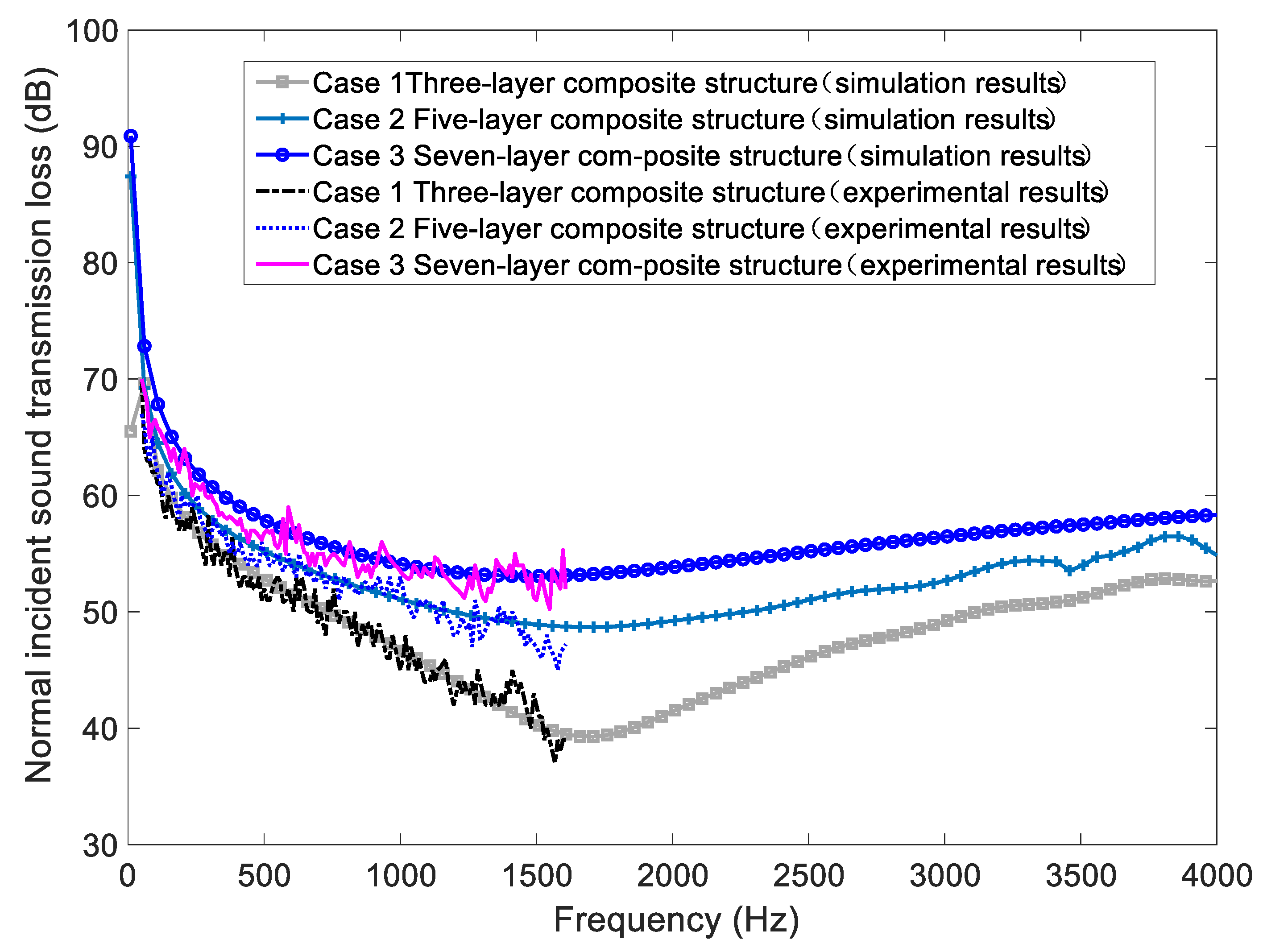
Based on the analysis of elastic panel and core layer parameters and the combination mode of partition structure, a better partition configuration of Case 3 was proposed according to the law affecting the sound insulation performance, and verified by experiments (Figure 10). The results show that the over-agreement between simulation and experimental junction was high, verifying the rationality of the configuration.
Case 1 was the basic reference configuration in this study, on the basis of which the parameter configuration was further optimized. Compared with Case 1, the sound insulation performance in Case 2 was improved by about 5 dB, and the average STL was 49 dB. However, further improvement was proved possible. In Case 3, based on the rules of parameter setting, the optimized partition configuration was composed of layered materials with different parameters, which effectively rectified the defects caused by resonance and coupling effects of single-layer wall and lightweight partition. The average STL value of the optimized configuration reached about 55 dB, forming a stable STL curve between the middle and low frequencies, indicating a significantly improved the sound insulation performance.
5. Conclusions
Based on the design process of CLD composite partitions, this study analyzed and discussed four parameters of the layered materials that influence the sound insulation performance, and proposed an optimized structure suitable for the space partition in the hotel. The proposed structure had a surface density of 36.3 kg/m2 and a thickness of 49 mm, which could make up for the relatively poor sound insulation performance of light partition currently used in the market and may achieve the goal of lightweight and high sound insulation. The major contributions of the study are summarized as follows:
- (1)
- The parameters of Young’s modulus, thickness, surface density and VEM damping core layer thickness of elastic panel are important factors influencing the sound insulation performance of CLD partitions.
- (2)
- As for lightweight and high sound insulation composite partition, the sound insulation performance can be improved by using different inter-layer combinations.
- (3)
- Adding VEM layer to the configuration can effectively suppress and reduce the resonance valley in the first stiffness control area, which thus can effectively improve the sound insulation performance of the whole structure.
Author Contributions
T.Q.: Conceptualization, Methodology, Software, Investigation, Writing—original draft. B.W.: Writing—review & editing, Software, Validation Investigation. H.M.: Conceptualization, Methodology, Writing—review & editing, Supervision, Funding acquisition, Project administration. All authors have read and agreed to the published version of the manuscript.
Funding
This work is supported by Opening Foundation of Key Laboratory of New Technology for Construction of Cities in Mountain Area, Ministry of Education, China (LNTCCMA-20210104). This work was also supported by the Natural Science Foundation of China (Grant No. 51408113) and the Natural Science Foundation of Jiangsu Province, China (Grant No. BK20140632).
Institutional Review Board Statement
Not applicable.
Informed Consent Statement
Not applicable.
Data Availability Statement
Data can be obtained from the corresponding author upon reasonable request.
Acknowledgments
The authors sincerely thank the editor for her meticulous and professional work.
Conflicts of Interest
The authors declare that they have no known competing financial interest or personal relationships that could have appeared to influence the work reported in this paper.
References
- Alves, J.A.; Silva, L.T.; Remoaldo, P.C.C. The Influence of Low-Frequency Noise Pollution on the Quality of Life and Place in Sustainable Cities: A Case Study from Northern Portugal. Sustainability 2015, 7, 13920–13946. [Google Scholar] [CrossRef] [Green Version]
- Kong, Z.; Jakubiec, J.A. Evaluations of long-term lighting qualities for computer labs in Singapore. Build. Environ. 2021, 194, 107689. [Google Scholar] [CrossRef]
- Kong, Z.; Utzinger, D.M.; Freihoefer, K.; Steege, T. The impact of interior design on visual discomfort reduction: A field study integrating lighting environments with POE survey. Build. Environ. 2018, 138, 135–148. [Google Scholar] [CrossRef]
- Kong, Z.; Zhang, R.; Ni, J.; Ning, P.; Kong, X.; Wang, J. Towards an integration of visual comfort and lighting impression: A field study within higher educational buildings. Build. Environ. 2022, 216, 108989. [Google Scholar] [CrossRef]
- Lin, J.; Tan, H.; Xu, C.; Shi, H.R. Research Progress of Acoustic Technology in Buildings. Build. Sci. 2013, 29, 10. [Google Scholar]
- Mansilla, J.; Masson, F.; Palma, I.D.; Pepino, L.; Bender, L. Sound Insulation of Homogeneous Single Panels: A Comparison Between Real Construction Materials and Several Prediction Models. In Proceedings of the 24th International Congress on Sound and Vibration, London, UK, 23–27 July 2017; pp. 1–8. [Google Scholar]
- Bader Eddin, M.; Ménard, S.; Bard Hagberg, D.; Kouyoumji, J.L.; Vardaxis, N.G. Prediction of Sound Insulation Using Artificial Neural Networks—Part I: Lightweight Wooden Floor Structures. Acoustics 2022, 4, 13. [Google Scholar] [CrossRef]
- Bader Eddin, M.; Vardaxis, N.G.; Ménard, S.; Bard Hagberg, D.; Kouyoumji, J.L. Prediction of Sound Insulation Using Artificial Neural Networks—Part II: Lightweight Wooden Façade Structures. Appl. Sci. 2022, 12, 6983. [Google Scholar] [CrossRef]
- Vardaxis, N.G.; Hagberg, D.B. Review of acoustic comfort evaluation in dwellings: Part III—airborne sound data associated with subjective responses in laboratory tests. Build. Acoust. 2018, 25, 289–305. [Google Scholar] [CrossRef]
- Vardaxis, N.G.; Hagberg, D.B.; Dahlström, J. Evaluating Laboratory Measurements for Sound Insulation of Cross-Laminated Timber (CLT) Floors: Configurations in Lightweight Buildings. Appl. Sci. 2022, 12, 7642. [Google Scholar] [CrossRef]
- Larbi, W.; Deü, J.F.; Ohayon, R. Vibroacoustic analysis of double-wall sandwich panels with viscoelastic core. Comput. Struct. 2016, 174, 92–103. [Google Scholar] [CrossRef]
- Hwang, S.; Kim, J.; Lee, S.; Kwun, H. Prediction of sound reduction index of double sandwich panel. Appl. Acoust. 2015, 93, 44–50. [Google Scholar] [CrossRef]
- Jung, W.; Gu, Z.; Baz, A. Mechanical filtering characteristics of passive periodic engine mount. Finite Elem. Anal. Des. 2010, 46, 685–697. [Google Scholar] [CrossRef]
- Pellicier, A.; Trompette, N. A review of analytical methods, based on the wave approach, to compute partitions transmission loss. Appl. Acoust. 2007, 68, 1192–1212. [Google Scholar] [CrossRef]
- Guptat, B.V.R.; Ganesan, N.; Narayanan, S. Finite element free vibration analysis of damped stiffened panels. Comput. Struct. 1986, 24, 485–489. [Google Scholar] [CrossRef]
- Zhou, X.Q.; Yu, D.Y.; Shao, X.; Wang, S.; Zhang, S.Q. Simplified-super-element-method for analyzing free flexural vibration characteristics of periodically stiffened-thin-plate filled with viscoelastic damping material. Thin-Walled Struct. 2015, 94, 234–252. [Google Scholar] [CrossRef]
- Moore, J.A.; Lyon, R.H. Sound transmission loss characteristics of sandwich panel constructions. J. Acoust. Soc. Am. 1991, 89, 777–791. [Google Scholar] [CrossRef]
- Aloufi, B.; Behdinan, K.; Zu, J. Vibro-acoustic model of an active aircraft cabin window. J. Sound Vib. 2017, 398, 1–27. [Google Scholar] [CrossRef]
- Tadeu, A.J.B.; Mateus, D.M.R. Sound transmission through single, double and triple glazing. Exp. Evaluat. Appl. Acoust. 2001, 62, 307–325. [Google Scholar] [CrossRef] [Green Version]
- Thamburaj, P.; Sun, J.Q. Effect of Material and Geometry on the Sound and Vibration Transmission across a Sandwich Beam. J. Vib. Acoust. 2001, 123, 205–212. [Google Scholar] [CrossRef]
- Yang, Y.; Fenemore, C.; Kingan, M.J.; Mace, B.R. Analysis of the vibroacoustic characteristics of cross laminated timber panels using a wave and finite element method. J. Sound Vib. 2021, 494, 115842. [Google Scholar] [CrossRef]
- Varanasi, S.; Bolton, J.S.; Siegmund, T.H.; Cipra, R.J. The low frequency performance of metamaterial barriers based on cellular structures. Appl. Acoust. 2013, 74, 485–495. [Google Scholar] [CrossRef]
- Li, J.; Li, S. Sound Transmission Through Metamaterial-Based Double-Panel Structures With Poroelastic Cores. Acta Acust. United Acust. 2017, 103, 869–884. [Google Scholar] [CrossRef]
- Kim, Y.; ASME, M. Identification of Acoustic Characteristics of Honeycomb Sandwich Composite Panels Using Hybrid Analytical/Finite Element Method1. J. Vib. Acoust. 2013, 135, 011006-1–011006-11. [Google Scholar] [CrossRef]
- Guerich, M. Optimization of Noise Transmission Through Sandwich Structures. J. Vib. Acoust. 2013, 135, 051010-1–051010-13. [Google Scholar] [CrossRef]
- Zhou, X.Q.; Zhang, S.Q.; Lin, W.W. Sound radiation characteristics analysis for the honeycomb reinforced laminated structures with viscoelastic material fillers through the asymptotic homogenous method. Compos. Struct. 2020, 245, 112266. [Google Scholar] [CrossRef]
- Li, Q.; Iu, V.P.; Kou, K.P. Three-dimensional vibration analysis of functionally graded material sandwich plates. J. Sound Vib. 2008, 311, 498–515. [Google Scholar] [CrossRef]
- Huang, C.; Nutt, S. Sound transmission prediction by 3-D elasticity theory. Appl. Acoust. 2009, 70, 730–736. [Google Scholar] [CrossRef]
- Chandra, N.; Raja, S.; Nagendra Gopal, K.V. Vibro-acoustic response and sound transmission loss analysis of functionally graded plates. J. Sound Vib. 2014, 333, 5786–5802. [Google Scholar] [CrossRef]
- Kurtze, G.; Watters, B.G. New Wall Design for High Transmission Loss or High Damping. J. Acoust. Soc. Am. 1959, 31, 739–748. [Google Scholar] [CrossRef]
- Li, J.; Li, S. Sound transmission through a damped sandwich panel. Acta Acust. United Acust. 2017, 80, 315–327. [Google Scholar]
- Wang, J.; Lu, T.J.; Woodhouse, J.; Langley, R.S.; Evans, J. Sound transmission through lightweight double-leaf partitions: Theoretical modelling. J. Sound Vib. 2005, 286, 817–847. [Google Scholar] [CrossRef]
- Nilsson, A.C. Wave propagation in and sound transmission through sandwich plates. J. Sound Vib. 1990, 138, 73–94. [Google Scholar] [CrossRef]
- Niu, B.; Olhoff, N.; Lund, E.; Cheng, G. Discrete material optimization of vibrating laminated composite plates for minimum sound radiation. Int. J. Solids Struct. 2010, 47, 2097–2114. [Google Scholar] [CrossRef] [Green Version]
- Bouzouane, B.; Ghorbel, A.; Akrout, A.; Abdennadher, M.; Boukharouba, T.; Haddar, M. Ultra-thin films effects on vibro-acoustic behaviour of laminated plate including a viscoelastic core. Appl. Acoust. 2019, 147, 121–132. [Google Scholar] [CrossRef]
- Chandra, N.; Gopal, K.V.N.; Raja, S. Vibro-acoustic response of sandwich plates with functionally graded core. Acta Mech. 2017, 228, 2775–2789. [Google Scholar] [CrossRef]
- Nilsson, A.; Baro, S.; Piana, E.A. Vibro-acoustic properties of sandwich structures. Appl. Acoust. 2018, 139, 259–266. [Google Scholar] [CrossRef]
- Assaf, S.; Guerich, M. Numerical Prediction of Noise Transmission Loss through Viscoelastically Damped Sandwich Plates. J. Sandw. Struct. Mater. 2008, 10, 359–384. [Google Scholar] [CrossRef]
- Santoni, A.; Schoenwald, S.; Fausti, P.; Tröbs, H.M. Modelling the radiation efficiency of orthotropic cross-laminated timber plates with simply-supported boundaries. Appl. Acoust. 2019, 143, 112–124. [Google Scholar] [CrossRef]
- Guyader, J.L.; Lesueur, C. Acoustic transmission through orthotropic multilayered plates, part I: Plate vibration modes. J. Sound Vib. 1978, 58, 51–68. [Google Scholar] [CrossRef]
- Guyader, J.L.; Lesueur, C. Acoustic transmission through orthotropic multilayered plates, part II: Transmission loss. J. Sound Vib. 1978, 58, 69–86. [Google Scholar] [CrossRef]
- Huang, C.; Nutt, S. An analytical study of sound transmission through unbounded panels of functionally gradedmaterials. J. Sound Vib. 2011, 330, 1153–1165. [Google Scholar] [CrossRef]
- Kang, L.; Sun, C.; An, F.; Liu, B. A bending stiffness criterion for sandwich panels with high sound insulation and its realization through low specific modulus layers. J. Sound Vib. 2022, 536, 117149. [Google Scholar] [CrossRef]
- Howson, W.P.; Zare, A. Exact dynamic stiffness matrix for flexural vibration of three-layered sandwich beams. J. Sound Vib. 2005, 282, 753–767. [Google Scholar] [CrossRef]
- Backström, D.; Nilsson, A.C. Modelling the vibration of sandwich beams using frequency-dependent parameters. J. Sound Vib. 2007, 300, 589–611. [Google Scholar] [CrossRef]
- Wang, C. Modal sound transmission loss of a single leaf panel: Effects of intermodal coupling. J. Acoust. Soc. Am. 2015, 6, 3514–3522. [Google Scholar] [CrossRef] [PubMed]
- Wang, C. Modal sound transmission loss of a single leaf panel: Asymptotic solutions. J. Acoust. Soc. Am. 2015, 138, 3964–13575. [Google Scholar] [CrossRef] [PubMed]
- GB 50118-2010; Code for Design of Sound Insulation of Civil Buildings. Ministry of Housing and Urban-Rural Development of the People’s Republic of China. China Architecture & Building Press: Beijing, China, 2010.
- Comsol Multiphysics. COMSOL Multiphysics User’s Guide; COMSOL, Inc.: Burlington, VT, USA, 2020. [Google Scholar]
- GB/Z 22764-2011; Acoustics-Determination of Sound Transmission Loss in Impendence Tubes-Transfer Matrix Method. Standardization Administration of China: Beijing, China, 2012.
- ASTM E2611-09; Standard Test Method for Measurement of Normal Incidence Sound Transmission of Acoustical Materials Based on the Transfer Matrix Method. ASTMInternational: West Conshohocken, PA, USA, 2009.
Figure 1.
Spectrum of normal incident STL of one typical single layer partition (12 mm gypsum board).
Figure 1.
Spectrum of normal incident STL of one typical single layer partition (12 mm gypsum board).
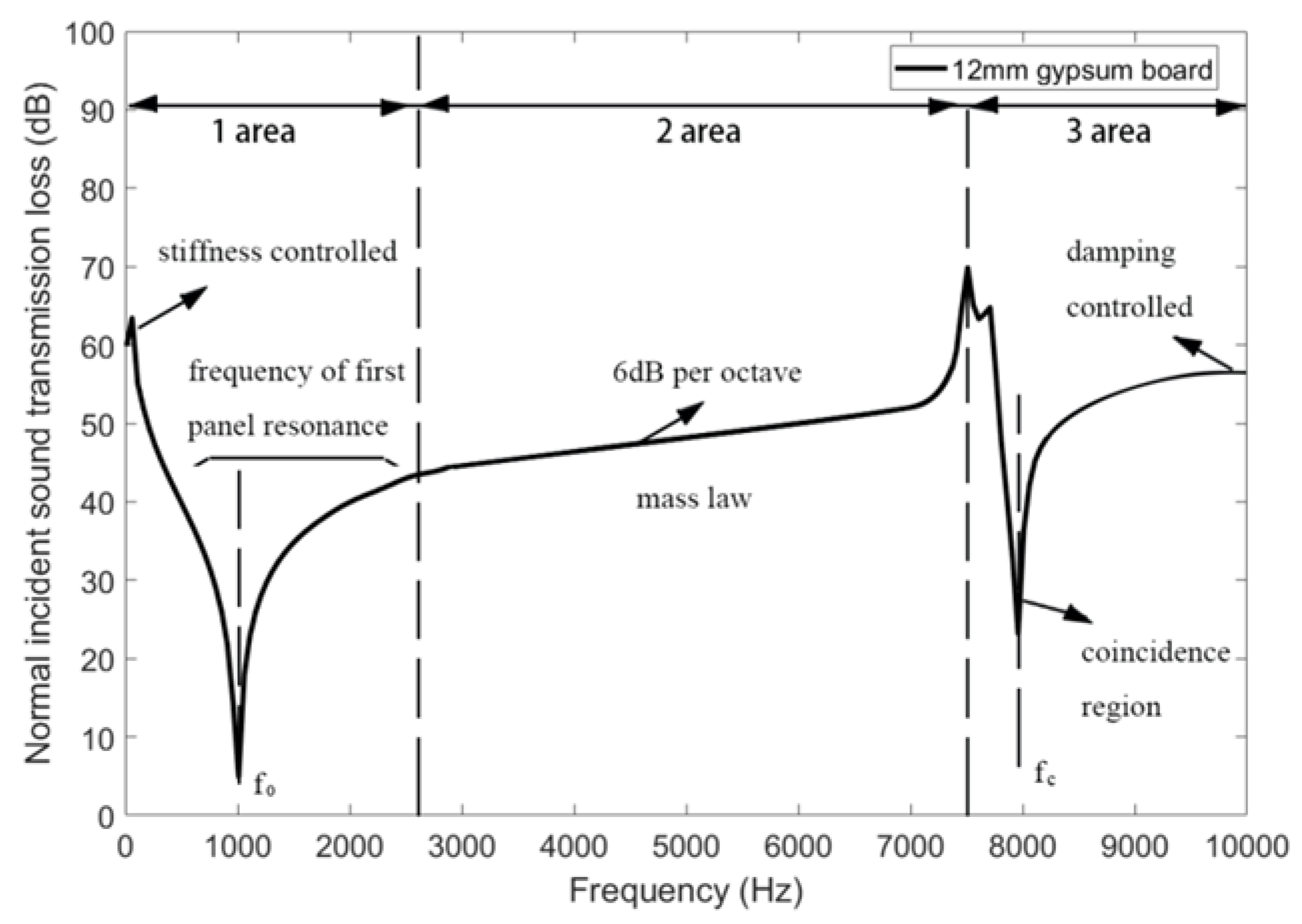
Figure 2.
Schematic diagram of calculation model for infinitely damped composite plate.
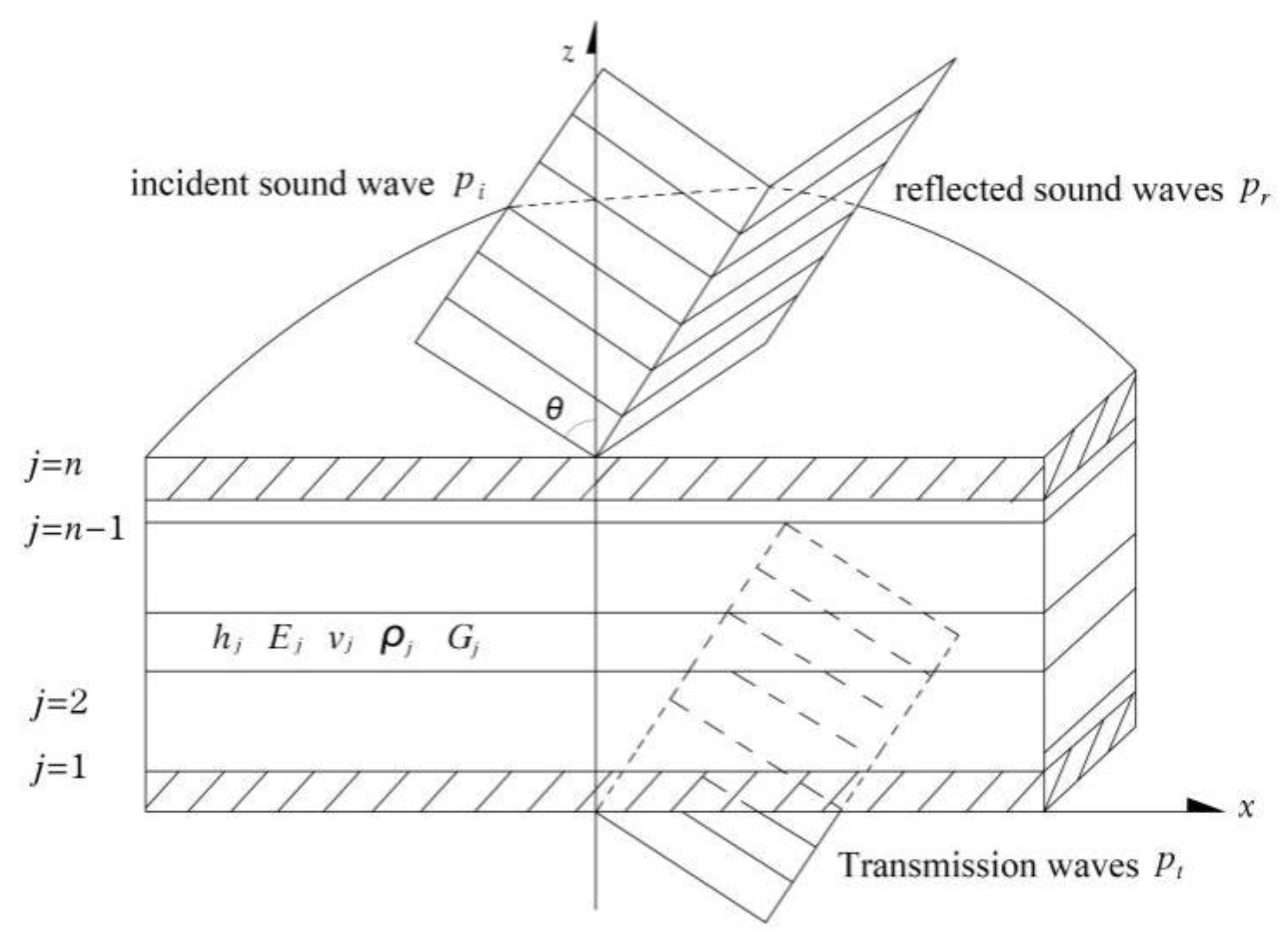
Figure 3.
(a) Schematic diagram of experimental measurement system for transmission loss of composite partition structure; (b) Field drawing for standing wave tube test measurement field drawing.
Figure 3.
(a) Schematic diagram of experimental measurement system for transmission loss of composite partition structure; (b) Field drawing for standing wave tube test measurement field drawing.
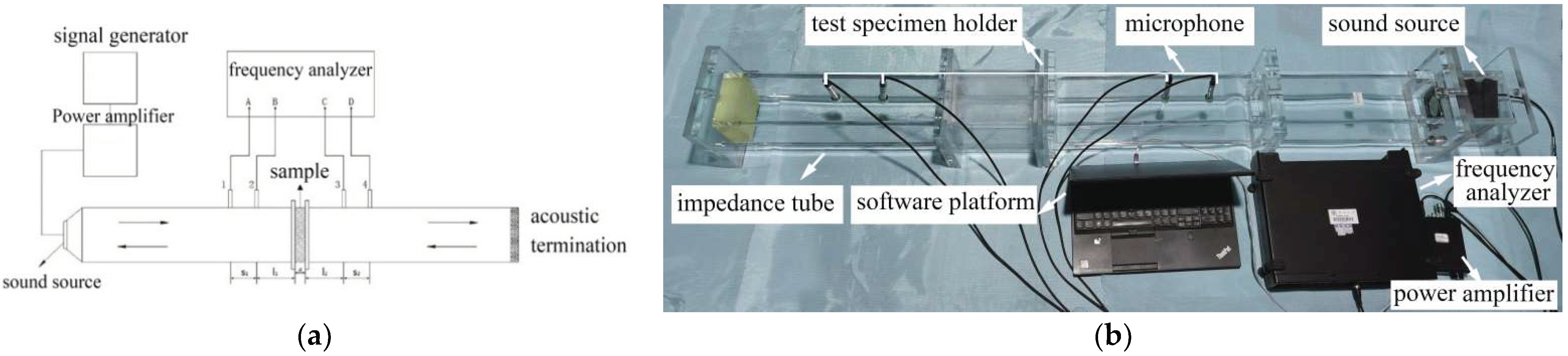
Figure 4.
Comparison of simulation and experimental results.
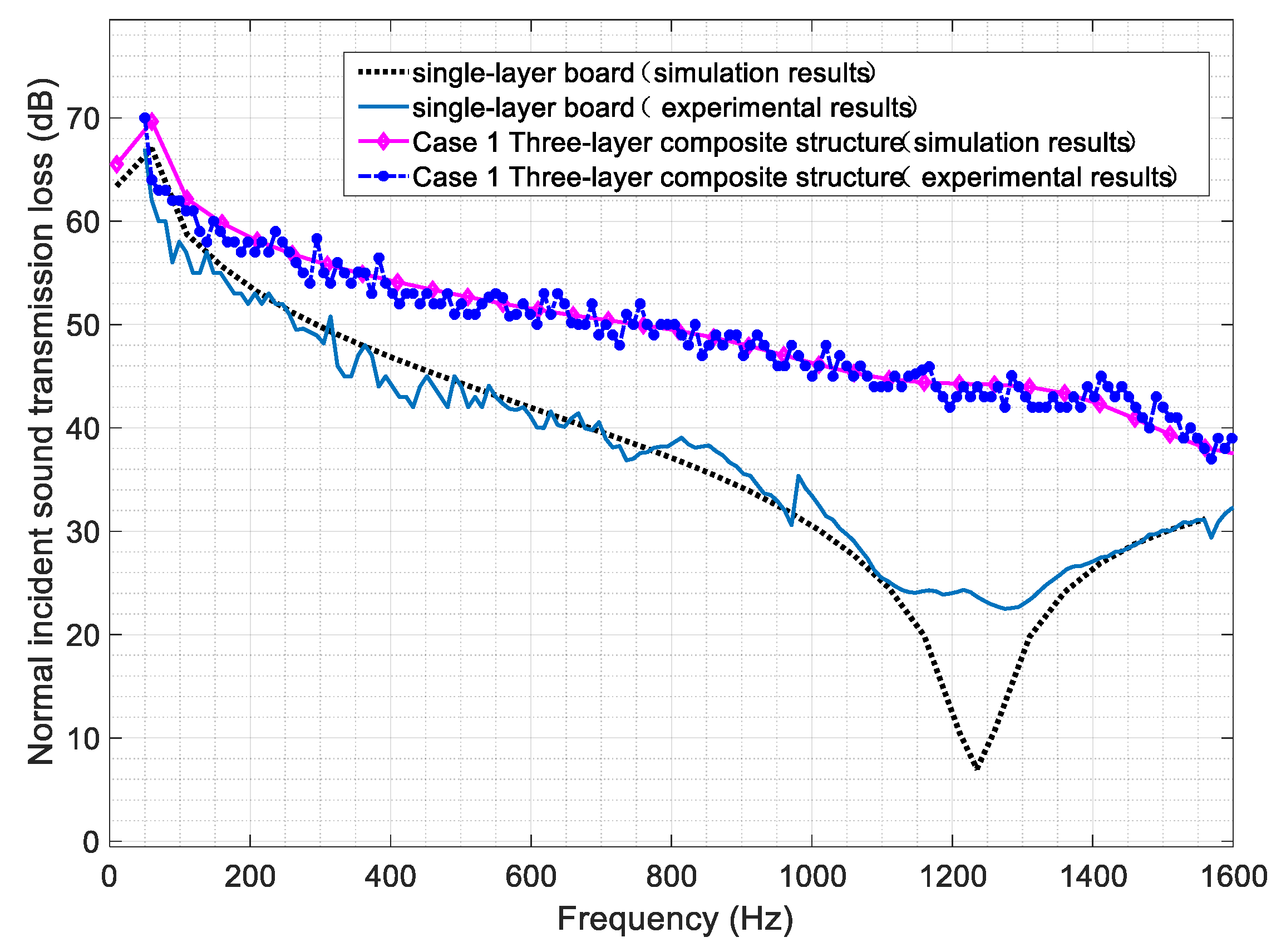
Figure 5.
The STL spectrum of the change of Young’s modulus with the set range.
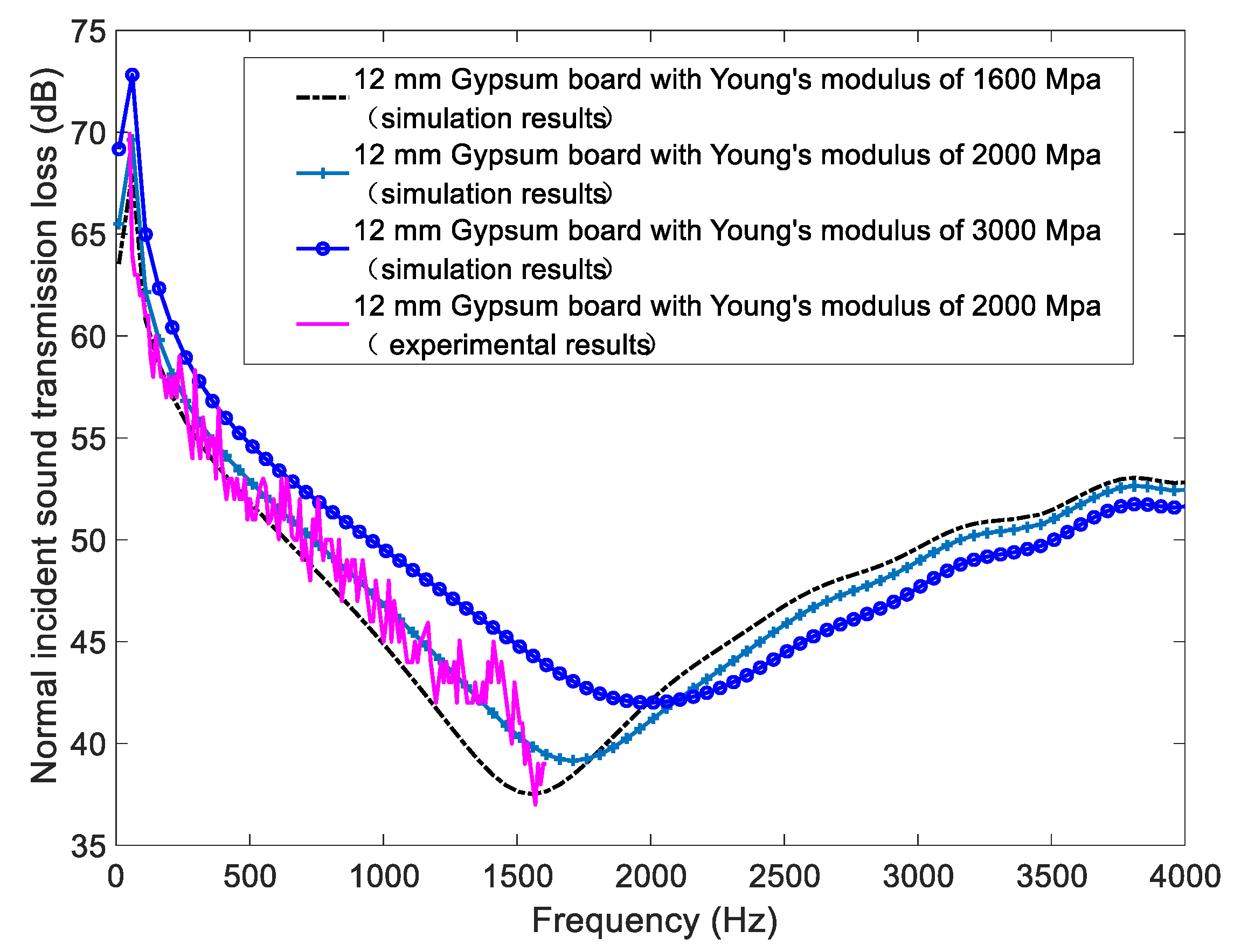
Figure 6.
The STL spectrum of the composite partitions with the change of gypsum boards’ thickness.
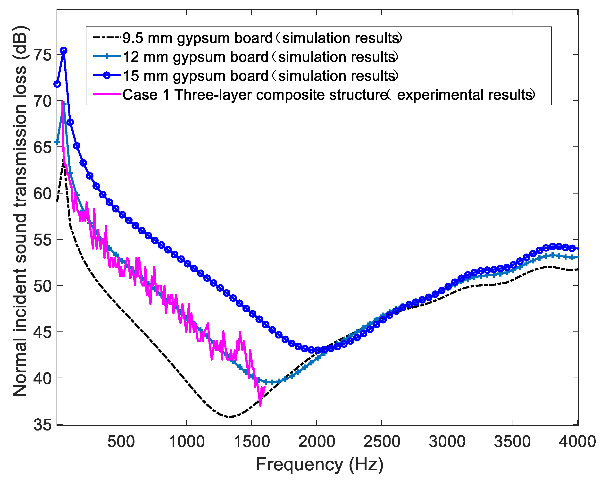
Figure 7.
The STL spectrum of the composite partitions with the change of gypsum board’s density.

Figure 8.
The STL spectrum of the composite partitions with the change of VEM core’s thickness.
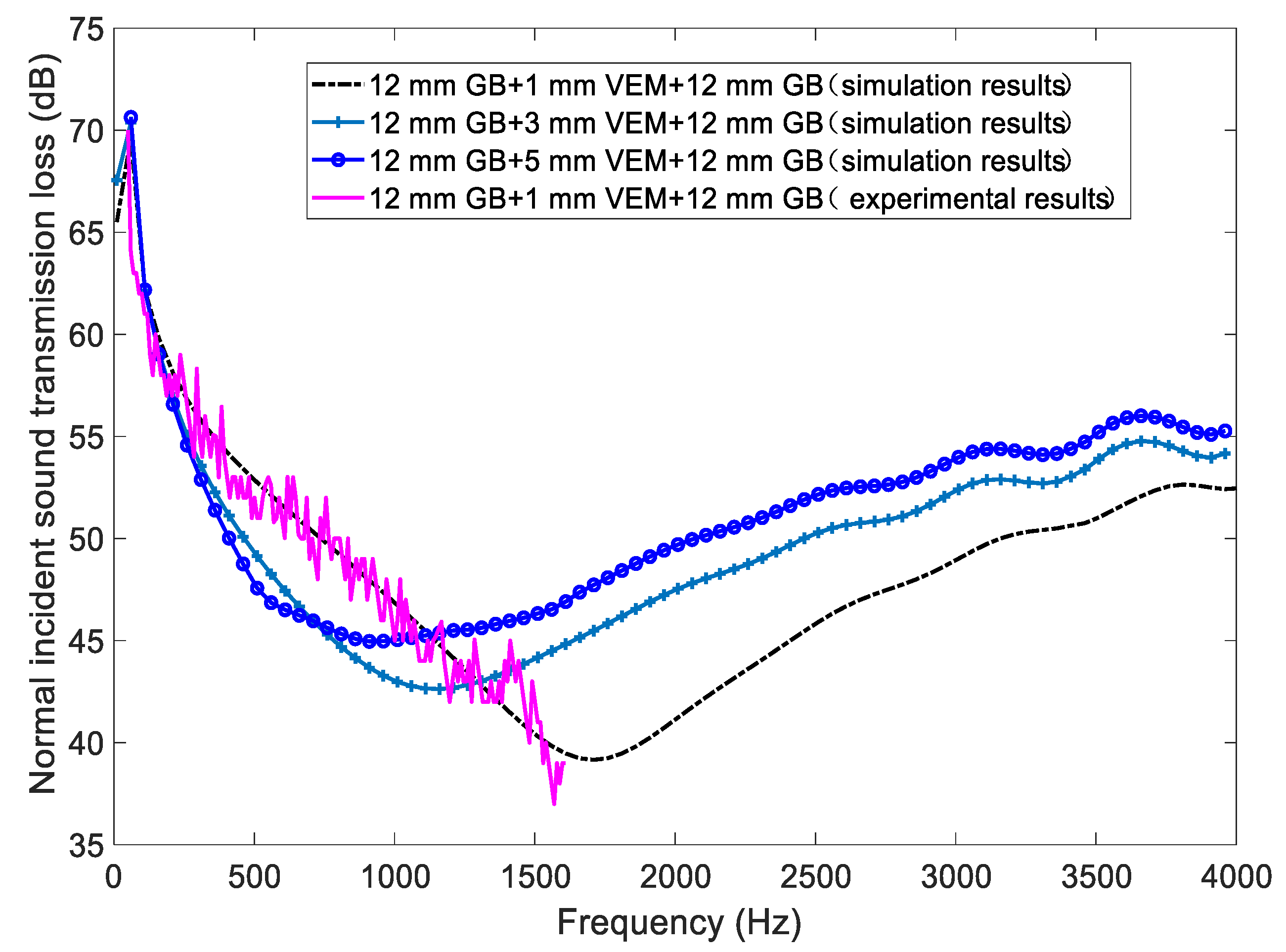
Figure 9.
The STL spectrum of the composite partitions with various inter-layers for VEM core and gypsum board.
Figure 9.
The STL spectrum of the composite partitions with various inter-layers for VEM core and gypsum board.
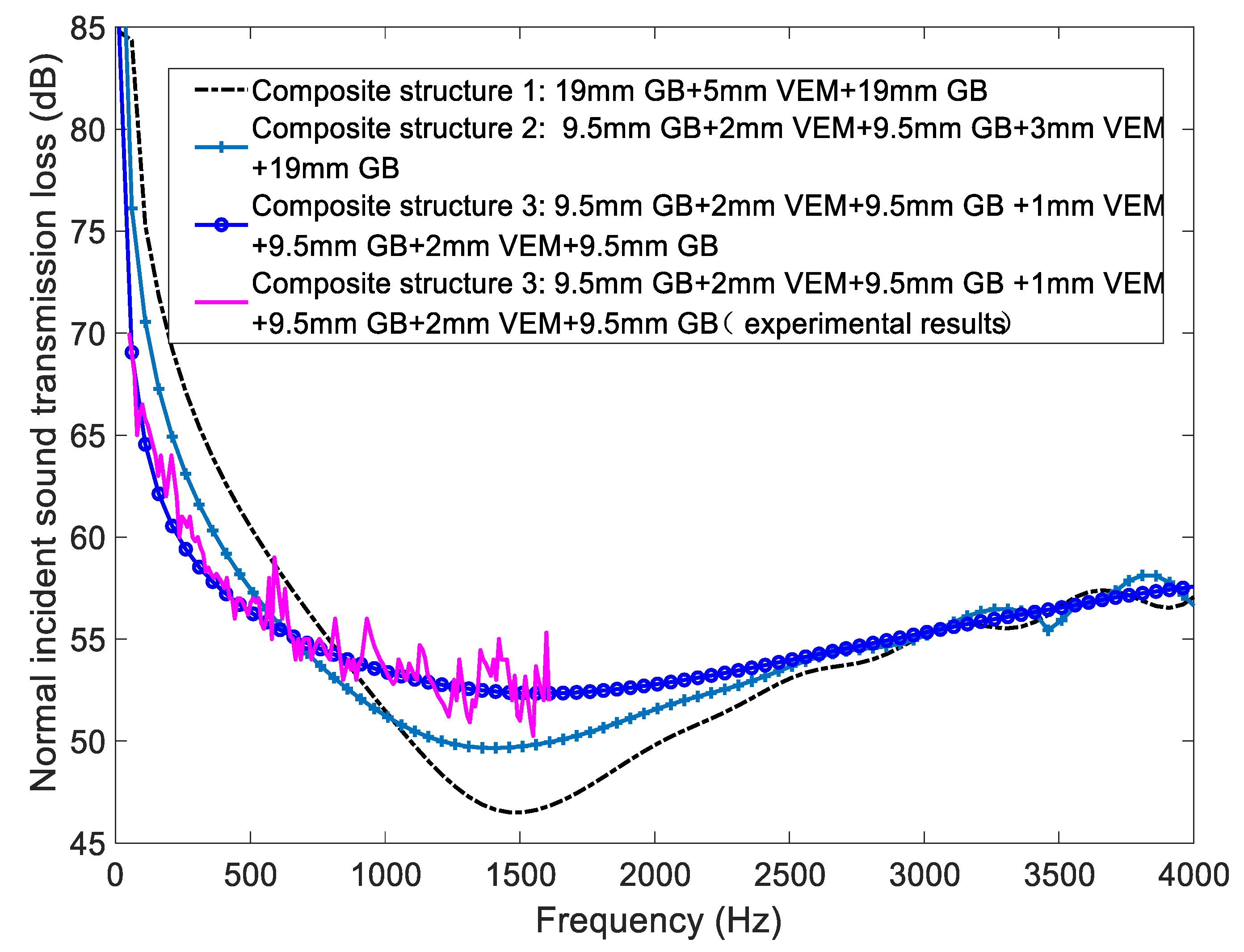
Figure 10.
Comparison of simulation and experimental results; STL trends represent the simulation and experimental results of Case 1, Case 2, Case 3.
Figure 10.
Comparison of simulation and experimental results; STL trends represent the simulation and experimental results of Case 1, Case 2, Case 3.

Table 1.
Simulated composite partition specifications and types.
| Name | Type | Material Specification (mm) | Thickness (mm) | Surface Density (kg/m2) |
|---|---|---|---|---|
| Case 1 | Three-layer composite structure | 12 gypsum board + 1 IIR + 12 gypsum board | 25 | 15.4 |
| Case 2 | Five-layer composite structure | 12 gypsum board + 2 IIR + 9.5 gypsum board + 1 IIR + 9.5 gypsum board | 34 | 23.8 |
| Case 3 | Seven-layer composite structure | 12 gypsum board + 3 IIR + 12 gypsum board + 2 IIR + 9.5 gypsum board + 1 IIR + 9.5 gypsum board | 49 | 36.3 |
Publisher’s Note: MDPI stays neutral with regard to jurisdictional claims in published maps and institutional affiliations. |
© 2022 by the authors. Licensee MDPI, Basel, Switzerland. This article is an open access article distributed under the terms and conditions of the Creative Commons Attribution (CC BY) license (https://creativecommons.org/licenses/by/4.0/).
Share and Cite
MDPI and ACS Style
Qu, T.; Wang, B.; Min, H. Lightweight Composite Partitions with High Sound Insulation in Hotel Interior Spaces: Design and Application. Buildings 2022, 12, 2184. https://doi.org/10.3390/buildings12122184
AMA Style
Qu T, Wang B, Min H. Lightweight Composite Partitions with High Sound Insulation in Hotel Interior Spaces: Design and Application. Buildings. 2022; 12(12):2184. https://doi.org/10.3390/buildings12122184
Chicago/Turabian StyleQu, Ting, Bo Wang, and Hequn Min. 2022. "Lightweight Composite Partitions with High Sound Insulation in Hotel Interior Spaces: Design and Application" Buildings 12, no. 12: 2184. https://doi.org/10.3390/buildings12122184
Note that from the first issue of 2016, this journal uses article numbers instead of page numbers. See further details here.