Article

Processing of AISI H11 Tool Steel Powder Modified with Carbon Black Nanoparticles for the Additive Manufacturing of Forging Tools with Tailored Mechanical Properties by Means of Laser Metal Deposition (LMD)

1
Institute of Photonic Technologies, Friedrich-Alexander-Universität Erlangen-Nürnberg, Konrad-Zuse-Straße 3/5, 91052 Erlangen, Germany
2
Erlangen Graduate School in Advanced Optical Technologies (SAOT), Friedrich-Alexander-Universität Erlangen-Nürnberg, Paul-Gordan-Straße 6, 91052 Erlangen, Germany
3
Institute of Manufacturing Technology, Friedrich-Alexander-Universität Erlangen-Nürnberg, Konrad-Zuse-Straße 3/5, 91052 Erlangen, Germany
4
Kazan National Research Technical University named after AN Tupolev—KAI, Karl Marx Street 10, Kazan 420111, Russia
*
Author to whom correspondence should be addressed.
Metals 2018, 8(9), 659; https://doi.org/10.3390/met8090659
Submission received: 31 July 2018 / Revised: 17 August 2018 / Accepted: 17 August 2018 / Published: 23 August 2018
(This article belongs to the Special Issue Additive Manufacturing of Ferrous Materials)

Abstract

:
Within the scope of the presented work the processing of AISI H11 (1.2343 or X37CrMoV5-1) tool steel powder modified by adding carbon black nanoparticles in varying concentrations by means of Laser Metal Deposition (LMD) is extensively investigated. On the basis of single weld track experiments, multi-layered cuboid-shaped samples made out of pure AISI H11 tool steel powder as well as modified tool steel powder mixtures were manufactured by applying various process parameters. The main scientific aim of the investigations was to achieve a basic understanding of the influence of the added carbon black nanoparticles on the resulting sample properties. For that purpose, the generated specimens were first analyzed with respect to relative density, inner defects, microstructure, Vickers hardness and chemical composition. Subsequently, the mechanical properties of post-heat-treated specimens were investigated, with the focus on the yield strength (Y0.2%), by means of compression tests. We prove that by adding carbon black nanoparticles to the initial AISI H11 powder, the formation of martensitic and bainitic phases, as well as the precipitation of carbides at the grain boundaries, are enhanced. As a result, a significant increase of Vickers hardness and of the compression yield strength by up to 11% can be achieved in comparison to samples made out of the unmodified AISI H11 powder. Furthermore, it can be fundamentally demonstrated that the fabrication of parts with layer-specific variable hardness can be realized by the controlled changing of the powder mixtures used during the layer-by-layer manufacturing approach.

Graphical Abstract

1. Introduction

An industrial application of Laser Metal Deposition (LMD), which is also denominated as Direct Metal Deposition (DMD), Laser Engineered Net Shaping (LENS) or Laser Cladding by powder injection, is the repair and maintenance of cost-intensive high-end parts like turbine blades [1] or forming tools [2]. Apart from repair applications, the deposition of wear- and corrosion-resistant coatings on the basis of metal matrix composites [3] or customized metallic alloys for highly loaded part surfaces has already been established in the industrial environment. With the continuous progression of the commercially available system technology and the CAD/CAM software tools used for data preparation and path planning of the laser processing head, the additive manufacturing of three-dimensional parts/structures by means of LMD becomes more and more popular. However, in contrast to repair and coating applications, the additive manufacturing of complete functional parts by means of LMD is primarily limited to scientific investigations and not yet established as a state-of-the-art manufacturing technology. Figure 1a shows the principle of the LMD process.
Here, the surface of a metallic substrate is locally fused by a high-power laser beam. At the same time, metallic powder is blown into the melt pool by a powder nozzle, which can be coaxially or laterally positioned to the incoming laser beam. In order to minimize the oxidation of the deposited metal inert gases like argon and helium are used as transport- and protection gas. After quick cooling down and rapid solidification of the laser-induced melt pool, a weld track is formed out onto the surface. By welding single weld tracks in an overlapping configuration next to each other and on top of each other, it is basically possible to fabricate three-dimensional parts on freeform surfaces using a layer-by-layer manufacturing approach. According to state-of-the-art knowledge, materials that can be processed by means of LMD are, among others, aluminum alloys [4], nickel-base alloys [2], titanium-alloys [2,5], stainless steels [6], low-carbon tool steels [7,8] and pure metals, e.g., nickel [4]. A comprehensive overview about the process-able materials and actual research topics in the field of LMD is presented in References [4,9].
In tool making, the focus of LMD is actually put on the repair of worn out tools, especially injection molds, or the deposition of wear- and corrosion-resistant coatings. In this context, the preferred materials are low-carbon maraging tool steels (e.g., 1.2709 (X3NiCoMoTi18-9-5)) and customized powders such as Stellite 21 [10] for the rebuilding of molds. In comparison to classical hot- and cold-work tool steels, which are commonly used as material for bulk forming tools, those types of steels possess an excellent weldability due to the low-carbon content. However, for the majority of applications in the field of bulk forming the mechanical strength and wear resistance of the above-named materials especially under thermal and dynamical load is not sufficient. For that purpose, the use of traditional high-carbon tool steels is indispensable.
The process ability of traditional high-carbon tool steels such as AISI H11 [11], AISI H13 [12,13] or also the cold-work tool steel 1.2358 (60CrMoV18-5) [14] by means of LMD has already been proven within the scope of several scientific studies. Thereby, the focus was, among others, set on the manufacturing and microstructural analysis of single weld tracks and thin wall structures [12,13]. Furthermore, the determination of mechanical properties by means of tensile- and compression-testing with respect to the applied processing parameters and post-heat-treatment strategy was the object of a few scientific investigations. Junker et al. demonstrated that after a conventional post-heat-treatment of AISI H11 consisting of austenitization and quenching followed by three-times annealing the mechanical properties of specimens manufactured by means of LMD are equivalent to the mechanical properties of post-heat-treated specimens fabricated by traditional subtractive manufacturing technologies [11]. Based on these investigations a forging tool with a total mass of 2.5 kg was fabricated. After mechanical finishing, the heat-treated tool was tested under conditions close to industrial serial production and subsequently characterized with respect to signs of fatigue and life time. Thereby, a promising tool performance was achieved, and the additively manufactured tool showed similar performance and nearly the same signs of fatigue as the traditionally fabricated ones [11].
A possibility to further enhance the mechanical strength and to improve the practical performance of additively manufactured tools could be to modify the initial tool steel powders with certain kinds of nano-scaled additives prior to the laser-based manufacturing process. By adding specific nanoparticles to the initial tool steel powder both the microstructure as well as the chemical composition and associated with that, the resulting mechanical part properties can be deliberately manipulated. The use of different types of nanoparticles as additives with the aim to change the melting and solidification behavior and to adapt the resulting sample properties was object of latest scientific research activities in the field of Laser Beam Melting (LBM) and LMD, respectively.
For example, as was shown by Reference [15] for different aluminum alloys, air-atomized metallic powders, which are possessing an irregular particle shape and related to a poor flowability, can be processed in an adequate way by means of LBM, due to the addition of a mixture of varying metallic nanoparticles. In addition to the improvement of the flowability, the final chemical composition of the manufactured aluminum samples could be modified/changed by this approach.
Apart from that, Gu et al. proved that the addition of TiC nanoparticles as additives in AlSi10Mg powder promotes grain refinement leading to a noticeable enhancement of mechanical strength in comparison to unmodified AlSi10Mg processed by means of LBM [16].
In Reference [17] ZrH2 nanoparticles were used to significantly improve the process ability/weldability of the high-strength aluminum alloys EN AW 6061 and EN AW 7075, which show a high susceptibility to cracking. By the modification of the initial aluminum powder with this type of nanoparticles the solidification behavior/dynamics of the melt pool could be changed, because the nanoparticles function as crystallization germs. In this way both grain refinement as well as a change in grain morphology is promoted and the susceptibility to cracking of these alloys can be significantly reduced.
Moreover, Bischof et al. verified the hardening and strengthening effect induced by adding carbon black nanoparticles in Fe-4800 powder for LBM. On the basis of the microstructural changes (enhanced formation of C-martensite) that can be directly correlated with the added amount of carbon black nanoparticles an increase in hardness from about 210 HV0.3 for samples made out of the pure Fe-4800 powder to 405 HV0.3 for specimens manufactured with a powder mixture containing 0.3 wt. % carbon black nanoparticles was achieved [18].
Additionally, in LMD the effect of nanoparticles added as additives to the initial micro-scaled metal powders was researched within the scope of a few scientific studies. For instance, Reference [19] investigated the processing of TiC/Inconel 625 composites by means of LMD. Thereby, the influence of the size of the TiC reinforcement particles on the microstructure and mechanical properties was extensively analyzed. Resulting from the added TiC nanoparticles, the microstructure of the Inconel 625 matrix could be modified and, related to this, micro hardness, tensile properties and wear resistance could be enhanced without noticeably sacrificing the ductility of the composite.
In this study, the influence of the addition of carbon black nanoparticles on the processing of the hot-work tool steel AISI H11 (1.2343) by means of LMD is investigated in detail. Thereby, the aim is to enhance the occurrence of hardening and strengthening metallurgical phases, e.g., martensite and the precipitation of carbides at the grain boundaries by means of in situ alloying of the added carbon black nanoparticles. In this manner, the mechanical strength of the manufactured tool steel samples shall be improved in comparison to specimens generated with the pure AISI H11 tool steel powder. In this context, the effect of the nanoparticle concentration on the hardness and yield strength is the scientific main focus of the presented approach.

2. System Technology, Materials and Experimental Procedure

2.1. Laser Metal Deposition (LMD) Setup

The presented experimental investigations were conducted with the Laser Metal Deposition machine TruLaser Cell 3008 (TLC 3008) of the company Trumpf GmbH + Co. KG (Ditzingen, Gemany), which is equipped with the DepositionLine Module. This commercially available 5-axis (x, y, z, A, C) LMD machine consists of a continuous wave (cw) disc laser (TruDisk 1000), which emits laser light with an average wavelength of 1030 nm and a maximum cw output power Pmax of 1 kW, a powder feeder unit with two powder hoppers (GTV PF2/2) and a laser processing head equipped with the laser optics and a three-way powder nozzle.
In order to reduce internal stresses and to analyze the influence of an additional pre-heating of the substrate during the manufacturing process, a current-controlled ceramic heating device was used for selected experiments, especially for processing the tool steel powder mixtures with high total carbon content (see Figure 1b). In this manner, a maximum pre-heating temperature of around 400 °C at the substrate surface can be adjusted. For measuring and for adapting of the pre-heating temperature, an arrangement of two type K thermocouples, which was directly fixed onto the substrate surface, was used. The applied thermocouples possess a measurement range from −200 °C to +1300 °C, a measurement accuracy of around 1 °C and a response time of about 100 ms.

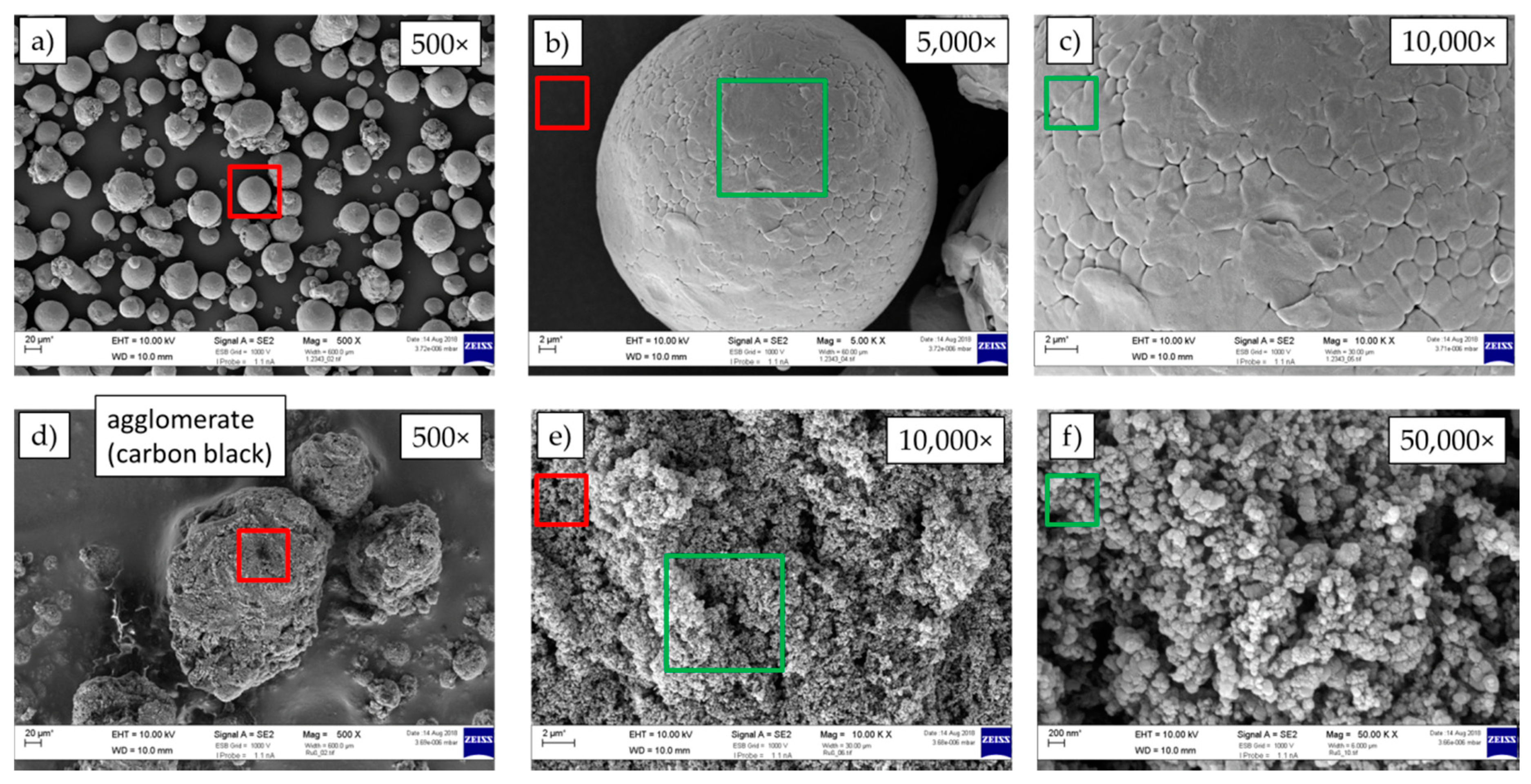
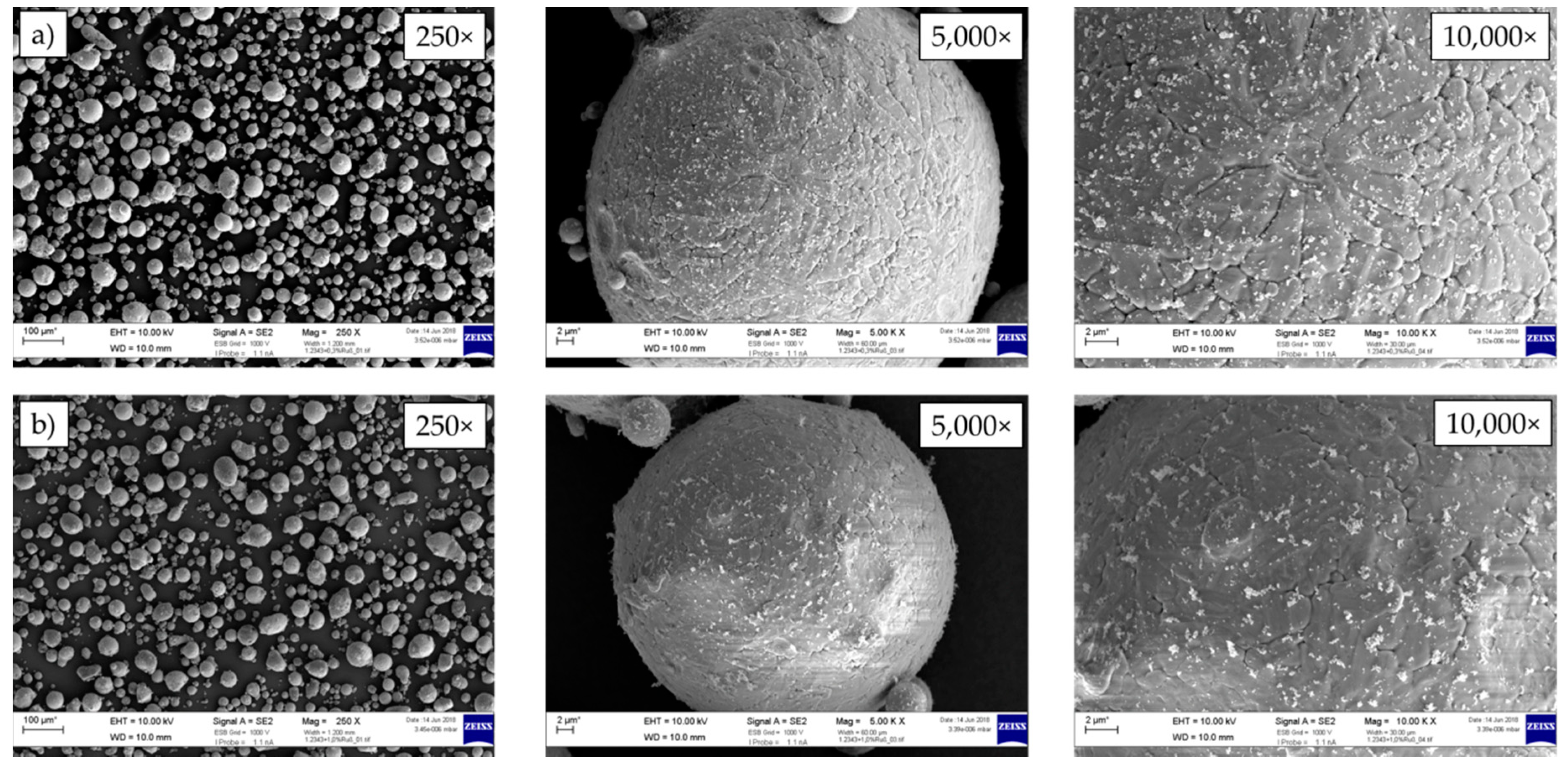
2.2. Materials, Material Preparation and Powder Properties

For the presented research, argon-atomized AISI H11 tool steel powder of TLS Technik GmbH & Co. Spezialpulver KG (Bitterfeld-Wolfen, Germany) was used. According to a chemical analysis of the powder externally performed at the Schaeffler Technologies AG & Co. KG (Herzogenaurach, Germany) by means of X-ray fluorescence (XRF) analysis and chemical hot-gas extraction the chemical composition complies with the reference values of AISI H11 (1.2343) given by Reference [20]. Table 1 shows the results of these investigations.
Figure 2a–c shows SEM images of the unsieved tool steel powder in different magnifications. It can be seen that the powder particles possess a predominately spherical particle shape with minor satellites and that only a few larger particles of irregular shape are present. Prior to the LMD process the AISI H11 powder was analyzed by means of static image analysis using a Camsizer XT from the company Retsch Technology GmbH (Haan, Germany) to determine the particle size distribution. Thereby it could be shown that the mean particle diameter of the unsieved AISI H11 powder ranges between 5 µm and 85 µm, whereby the expected value d50% was determined to 41.4 µm.
The used carbon black nanoparticles (official notation: N550 carbon black) were purchased from Harald Scholz & Co. GmbH (Partenstein, Germany). According to the powder supplier, the mean particle size approximately varies between 50 nm and 100 nm (see also Figure 2d–f) and the carbon content corresponds to approximately 99%.
As substrates, soft-annealed plates (200 mm × 200 mm × 15 mm) made out of AISI H11 tool steel were used. The exact chemical composition of the substrate material is also shown in Table 1.
Prior to the preparation of the tool steel/carbon black powder mixtures, the tool steel powder was dried in a chamber kiln (type N 11/HR from Nabertherm GmbH, Lilientahl, Germany). At a temperature of around 100 °C under ambient atmosphere for several hours the residual moisture content was reduced and associated with this procedure the flowability of the initial tool steel powder was increased. After that the powder was sieved with a mesh size of 63 µm in order to remove larger irregular-shaped particles and powder agglomerations, which also promote a decrease of flowability.
After the preparation by means of drying and sieving, the mass ratio of AISI H11 tool steel and carbon nanoparticle powder was determined by weighing. Subsequently, the powder mixtures were mixed in a so-called TURBULA-mixing device from Willy A. Bachhof Maschinenfabrik AG (Basel, Switzerland). Thereby, the added carbon nanoparticles adhered to the surface of the micro-scaled tool steel particles due to the huge tension forces acting on the nanoparticles (see Figure 3). In this context, one of the most important parameters seems to be the mixing time. To achieve a homogenous distribution of the carbon nanoparticles on the surface of the tool steel particles, the mixing time for a total powder mass of 0.5 kg should not be less than 2 h. After mixing the prepared powder mixtures were subject to a second sieving step using a sieve with a mesh size of 100 µm to remove larger powder particle agglomerations promoting a deterioration of the powder flowability. At this point it has to be mentioned that the amount of removed particle agglomeration by the second sieving procedure is negligibly small if the mixing duration is appropriately selected.
By the above described procedure, tool steel powder mixtures with an additional carbon nanoparticle concentration between 0.1 wt. % and 1 wt. % were prepared.
Up to a nanoparticle concentration of 0.5 wt. % the prepared powder mixtures show an adequate flowability, so that a homogeneous and reproducible powder mass flow could be realized. As is exemplarily illustrated in Figure 3, a homogenous distribution of the carbon black nanoparticles on the surface of the tool steel particles could be observed for a nanoparticle concentration being less or equal to 0.5 wt. %. One indicator for the adequate flowability of the prepared powder mixtures is the strong linear relationship (linear regression) between the number of rotations per minute (rpm) of the dosing plate of the powder feeder and the experimentally determined powder mass flow (see Figure 4). For small nanoparticle concentrations being less or equal to 0.2 wt. % the additives even increase the flowability resulting in a rise of the slope of the regression curves in comparison to the pure tool steel powder. Just with increasing nanoparticle concentration the flowability decreases. Powder mixtures with a nanoparticle content being larger than 0.5 wt. % are no longer capable of flowing, so these powder mixtures were not considered for further investigation.

2.3. Experimental Procedure and Processing Parameters

In the first step, single weld tracks of the unmodified AISI H11 powder and the prepared tool steel powder mixtures were generated on the substrate plates by applying various process parameter combinations. In this manner the influence of the added carbon on the process ability and the resulting geometric characteristics of the single weld tracks were analyzed.
Table 2 presents the investigated sets of processing parameters used for both the single weld track experiments and the manufacturing of cuboidal, multi-layered samples. At this point it has to be highlighted that only process parameter combinations that are appropriate for manufacturing of nearly fully dense and crack-free volumetric samples made out of the unmodified AISI H11 powder are considered for investigating the effect of the added nanoparticles on the resulting sample properties. For the performed single weld track experiments the laser power P was varied between 600 W and 1 kW in steps of 100 W, while the powder mass flow was changed between 2.7 ± 0.1 g/min and 3.7 ± 0.1 g/min. All experiments were realized with a constant feed rate frate of 400 mm/min. The working distance D, which is equivalent to the distance of the nozzle tip to the substrate surface or last deposited and solidified weld track layer, was kept constant at 12 mm. In addition, the laser spot diameter dlaser was set to about 1.5 mm for all experiments. Furthermore, the protection gas (argon) stream took a constant value of 20 L/min and the transport (helium) gas stream was permanently adjusted to 8 L/min.
For getting a statistically significant result at least four weld tracks were generated for each process parameter combination and powder mixture. These weld tracks were then prepared to vertical cross sections by grinding and polishing with diamond suspension (6 µm, 3 µm and 1 µm grain size of diamond particles) using a metallographic standard procedure. Subsequent to the metallographic preparation, cross sections of the single weld tracks were investigated by means of optical microscopy in order to determine the weld track height, h, weld track width, w, and the area, Atrack, of the deposited weld track cross section (see Figure 5a). For that purpose, the Keyence Inc. digital optical light microscope VHXZ (Osaka, Japan) was used. For investigating the depth of the dilution zone and heat affected zone (HAZ) the polished cross sections were additionally etched using V2A etchant (100 mL HCl, 100 mL H2O, 10 mL HNO3, 4 droplets of restrained pickling solution). Furthermore, the powder catchment efficiency η of the single weld tracks was analytically estimated based on the determined weld track cross section Atrack, the feed rate frate the mass density ρ (7.7 kg/dm3 [20]) of AISI H11 and the experimentally determined powder mass flow m ˙ according to Equation (1) [4].
η = ρ A t r a c k   f r a t e m ˙
On the basis of the single weld track experiments near-net shaped, ashlar-formed samples made out of the different tool steel powder mixtures were generated using the same sets of process parameters as for the single weld track experiments (see Table 2). For the fabrication of near-net shaped specimens with adequate properties, a correct z-height increment is essential in order to deposit each weld track layer with the same powder and laser density. To determine the right z-height increment, a procedure, which is displayed in Figure 5b, was applied. In a first run a single weld track layer consisting of 25 single weld tracks was generated and subsequently, the resulting layer height was measured. The determined height was then used as z-height increment for manufacturing of samples with four layers. Based on the determined height of these specimens, the z-height increment was modified/corrected and used for the generation of ten-layered volumetric samples. The hatch distance between two overlapping and parallel weld tracks was constantly set to the half of the determined mean single weld track width, w. Furthermore, the samples were generated by applying a simple alternating line-like deposition strategy with an additional deposition of contour weld tracks.
After the LMD process the manufactured four- and ten-layered cuboidal samples were prepared to metallographic cross sections by means of grinding, polishing and etching and subsequently characterized with respect to relative density/inner defects, microstructure, hardness and chemical composition. The relative density of the samples was determined by means of microscopic analysis of highly polished cross sections. For this purpose, a series of single images for each sample were evaluated in terms of the pixel brightness using standard image processing algorithms. Based on this procedure the relative density was analytically estimated by calculating the ratio between the numbers of bright pixels to the total numbers of pixels within the region of interest.
For the analysis of the microstructure the polished cross sections of the samples were chemically etched and subsequently analyzed by optical microscopy. In this context, two varying etching techniques were applied to investigate and to identify the influence of the added carbon nanoparticles on the resulting microstructure. On the one hand the cross sections were etched applying V2A etchant (HCl, H2O, HNO3). This etching method is commonly used for martensitic steels in order to reveal carbides and grain boundaries [21]. On the other hand, the cross sections were treated according to Beraha I (H2O, HCl, (NH4)HF2), which is an established color etching technique to identify martensitic and bainitic phases of hardened steels and chrome steels and to reveal chrome carbides and residual austenite [21].
Furthermore, pre-selected samples were analyzed by means of energy dispersive X-ray (EDX, Carl Zeiss, Jena, Germany) measurements for investigating the elemental distribution of the main alloying elements (carbide formers) at the grain boundaries. For that purpose, the Gemini II field emission scanning electron microscope (SEM) from Carl Zeiss Microscopy GmbH (Jena, Germany), which is equipped with an additional EDX-detector of Oxford Technology, was used. To achieve accurate information about the chemical composition, especially the resulting carbon content of manufactured samples, an optical emission spectroscopy was performed. These investigations were carried out at the company FAG Aerospace GmbH & Co. KG (Schweinfurt, Germany). The analysis of the hardness distribution was conducted with the Vickers hardness tester HP30S from Hegenwald und Peschke Mess und Prüftechnik GmbH (Nossen, Germany), which is equipped with a high-precision and programmable x, y-positioning stage. This measurement device allows a spatially high resolution measurement of Vickers hardness (hardness distribution) at polished sample cross sections.
For achieving a fundamental understanding of the influence of the added carbon nanoparticles on the mechanical properties with the focus on the compression yield strength (Y0.2%), compression tests were performed. For this purpose, cuboidal specimens (10 mm × 10 mm × 12 mm) consisting of at least 35 single weld track layers were directly manufactured on the tool steel substrate plates (see Figure 5a). After that, the specimens were heat-treated by annealing at around 550 °C under ambient atmosphere for 2 h. For the post-heat-treatment a chamber kiln (type N 11/HR from Nabertherm GmbH, Lilientahl, Germany) was available. Subsequently, the annealed samples were mechanically treated by milling, wire-cutting and grinding to the final cylindrical testing geometry. The cylindrical compression specimens possess a diameter of 6 mm and a height of 9 mm. The compression tests according to DIN 50106 were performed at the Institute of Manufacturing Technology on a universal testing machine Walter + Bai FS300 from Zwick GmbH & Co. KG (Ulm, Germany) with a maximum load of 300 kN. The compression velocity was kept constant at 5 mm/min for all experiments. The specimens were compressed to 50% of their initial height. Due to the high load during the tests a carbide tool was used, in order to minimize signs of wear and, therefore, the influence of varying friction during testing. For constant low friction conditions, a Teflon film was put in between the specimen and the tool. The recorded force-displacement diagrams and the geometric characteristics of the cylindrical compression specimens were used to determine the stress-strain curves (flow curves) of the samples with respect to the added carbon black nanoparticle concentration. On the basis of the flow curves the compression yield strength (Y0.2%) of the specimens was deduced. Furthermore, the evaluation of the ductility of the specimens with respect to the added nanoparticle concentration was done by analyzing the stress-strain curves in detail.

3. Results and Discussion

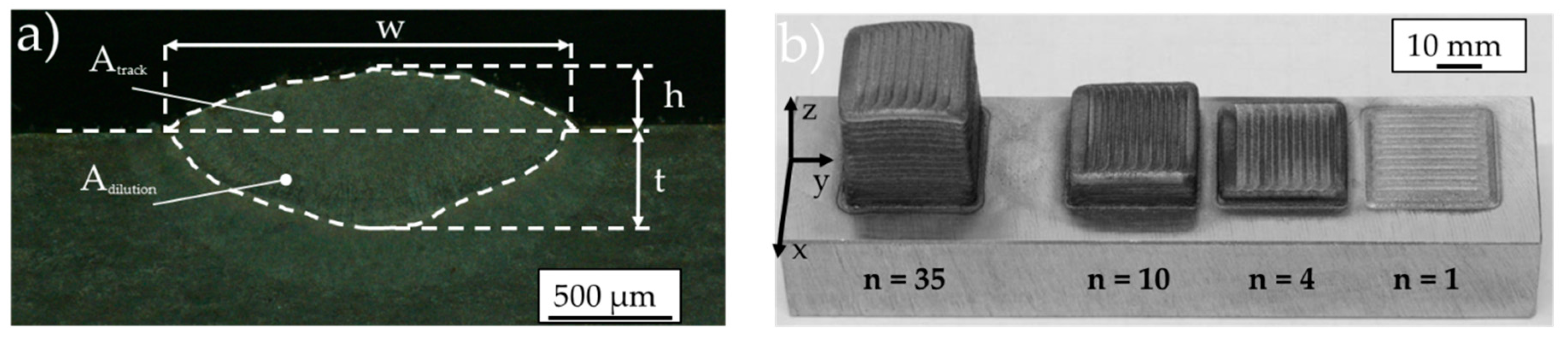
3.1. Influence of Nanoparticle Concentration on the Geometric Characteristics of Single Weld Tracks

At the beginning of the presented approach, single weld track experiments were performed with both the unmodified tool steel powder and the prepared powder mixtures to investigate the influence of the added carbon black nanoparticles on the resulting geometric characteristics of the single weld tracks.
Figure 6a–f above shows the experimentally determined width, height and the depth of dilution zone of the single weld tracks with respect to laser power and the applied powder mass flow for the investigated modified tool steel powder mixtures and the pure AISI H11 powder. Thereby, a steep rise of both the weld track width w and the maximum depth of the dilution zone t are observed with increasing laser power for all processed powders. Whereas, in consideration of the calculated standard deviations, the powder mass flow has no relevant impact on the resulting weld track widths and depth of dilution (see Figure 6). In contrast to the weld track widths and to the depth of the dilution zone, the influence of the laser power on the resulting single track height is lower. In this context, only a slight grow-up of single track height is recognized with increasing laser power for all investigated powder mixtures. On the contrary, as expected, an increase of the powder mass flow at constant laser power leads to noticeable rise of the single weld track height for both the pure AISI H11 powder and the modified powder mixtures (see to Figure 6c,d).
By analyzing Figure 6a–f with respect to the added carbon black nanoparticle concentration, the tendency seems to be apparent that for weld tracks manufactured with the same set of process parameters the width, the height and the depth of the dilution zone slightly increase with increasing nanoparticle concentration.
Figure 7 presents the powder catchment efficiency estimated by Equation (1) as function of the laser power and the powder mass flow for all processed powder mixtures. As expected, due to the rise of weld track width and height with increasing carbon black content the determined powder catchment efficiency is also affected by the nano-scaled additives. Thereby, a noticeable increase of the powder catchment efficiency for weld tracks deposited with the same set of process parameters can be detected with increasing amount of added carbon black nanoparticles.
Consequently, at this stage it can be concluded that the added carbon black nanoparticles show an influence on the resulting geometric characteristics of the deposited single weld tracks. Thereby, the addition of carbon black nanoparticles presumably leads to a higher laser light absorption. In this manner the total laser-induced thermal energy input is enhanced and related to this, the weld track width, height, the depth of dilution zone and the powder catchment efficiency increase. However, to confirm this assumption both thermographic investigations of the manufacturing process for determining the melt pool temperature, as well as calorimetric measurements with a similar experimental setup as suggested by Reference [22] to estimate the absorptivity of the powder with respect to the concentration of added nanoparticles, are required.

3.2. Influence of Nanoparticle Concentration on Relative Density and Chemical Composition

On the basis of the single weld track experiments, ashlar-formed samples were manufactured using the process parameter combinations presented in Table 2. As already mentioned above, only processing parameters were considered leading to nearly fully dense and defect-free specimens (relative density ρrel ≥ 99.5%) made out of pure AISI H11 tool steel powder.
Figure 8 shows metallographic cross sections of ten-layered samples made out of both the unmodified tool steel powder and the modified tool steel powder mixtures containing up to 0.5 wt. % carbon black nanoparticles for a laser power of 800 W and a powder mass flow of 2.7 ± 0.1 g/min. An overview about the determined relative densities of the manufactured samples with respect to the applied laser power, powder mass flow and the nanoparticle concentration is shown in Figure A1 (see Appendix A). Regardless of the used laser power and powder mass flow, samples made out of powder mixtures with additional carbon content smaller or equal to 0.2 wt. % possess a high relative density in the order of 99.9% (see also Figure A1). These samples are free of inner defects like cracks, larger voids/pores or oxide inclusions. By analyzing the polished cross sections at high resolution using optical light microscopy, the mean pore size of the samples is determined to about 20 µm. Consequently, for a carbon black nanoparticle concentration of up to 0.2 wt. % no significant differences of the relative density can be identified between samples generated with the pure AISI H11 powder and the ones made out of the modified powder mixtures.
With increasing concentration of the added carbon black nanoparticles (>0.2 wt. %), the formation of micro cracks is observed for the four- and ten-layered specimens and for all investigated process parameter combinations, as is shown in Figure 8. In this context, the presence of cracks seems to be enhanced with an increasing concentration of added nanoparticles and an increasing number of deposited weld track layers. The main reason for the high susceptibility to cracking of samples with an additional carbon black content larger or equal to 0.3 wt. % seems to be a stronger formation of brittle martensitic phases related to the rapid solidification and quick cooling-down of the melt pool and the high total carbon content of these tool steel powder mixtures. Thereby, the residual stresses locally exceed the damage threshold of the material, leading to cracking. As the microscopic analysis of etched cross sections presented in Figure A2 (Appendix A) illustrates, the cracks preferably appear between the acicular/columnar-like grains. These cracks partially possess a length of several hundred micrometers and are predominantly oriented in direction of the process-inherent temperature gradients induced by the layer-by-layer manufacturing approach.
In order to reduce the temperature gradients and associated with this to achieve a low-stress manufacturing process, a ceramic heating device was implemented in the experimental setup for preheating the substrate to a maximum temperature of about 400 °C (see Figure 1b). In this manner, for the higher pre-heating temperatures being larger or equal to 300 °C the formation of brittle martensite should be significantly attenuated or in an ideal case avoided because the sample is permanently kept on a temperature level in the order of or above the martensite start temperature of AISI H11 (martensite start temperature: TMartensite = 321 °C [23]) during the layer-wise manufacturing procedure.
Analyzing the metallographically prepared cross sections of four- and ten-layered samples with a carbon black content between 0.3 wt. % and 0.5 wt. %, it is recognizable that the formation of cracks in the core volume of the samples can be noticeably reduced for pre-heating temperatures in the order of or above the martensite start temperature of AISI H11 (see Figure 9). However, within the transition zone between the core and the contour (surrounding weld tracks), cracks are still present. Apart from that, in the transition zone the formation of large pores is observed for ten-layered samples (see Figure 9b). The enhanced occurrence of these defects probably results from an overheating of the melt pool in the upper sample region above the fifth layer. The overheating of the melt pool could lead to evaporation of alloy constituents or thermodynamic instabilities like spatter formation or collapsing of the melt pool. Both are possible reasons for the formation of large pores. Nevertheless, to prove this thesis further investigations are required. In this context thermographic process analysis will be performed to get an idea about the temperature development during the additive manufacturing process. In addition, high-speed camera-based process observation has to be carried out to investigate and to understand the melt pool dynamics with respect to the applied pre-heating, the processing parameters and the deposition strategy of the weld tracks.
At this stage it can be concluded that for the successful processing of powder mixture with higher carbon black nanoparticle concentration, both the applied pre-heating strategy and technical heating concept as well as deposition strategy of the weld tracks has to be modified and improved to prevent crack formation and to generate parts with promising mechanical characteristics for applications in the field of tool making.
In order to determine the chemical composition, samples up to a carbon black content of 0.2 wt. % were analyzed by means of optical emission spectroscopy (OES). As already mentioned above, these investigations were performed with kind support of the FAG Aerospace GmbH & Co. KG (Schweinfurt, Germany). Table 3 presents the mean values of the measured chemical composition in wt. % for the main alloying elements (carbon, chrome, molybdenum and vanadium).
Regardless of the analyzed sample, the concentration of the main alloying elements (Cr, Mo, V) is in good accordance with the material reference of AISI H11 presented by Reference [20]. Independent from the applied laser power the identified carbon content of the samples generated with the pure, unmodified tool steel is more or less equal to the carbon content of the initial tool steel powder. In contrast, the measured carbon content of the samples—which are manufactured on the basis of the tool steel powders modified by adding carbon black nanoparticles (0.1 wt. % and 0.2 wt. %)—is noticeably smaller than the total carbon content of the initial prepared powder mixtures. This deviation in the order of about 20% for both an added nanoparticle content of 0.1 wt. % and 0.2 wt. % can presumably be explained by a loss of nanoparticles during the transportation of the powder from the powder feeder to the powder nozzle and interaction (process) zone, respectively. In contrast, a carbon loss due to evaporation of carbon during the interaction with the laser beam seems to be implausible because of the high evaporation temperature of carbon black. A simple possibility to reduce the carbon loss could be to shorten the transport distance between powder feeder and powder nozzle.
However, at this point it can be concluded that adding carbon nanoparticles to the tool steel powder can be an appropriate way to adapt and enhance the carbon content in tool steel powders, and to adjust and change the mechanical properties of parts additively manufactured by means of LMD.

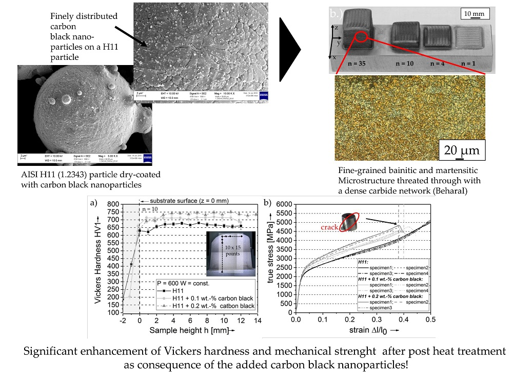
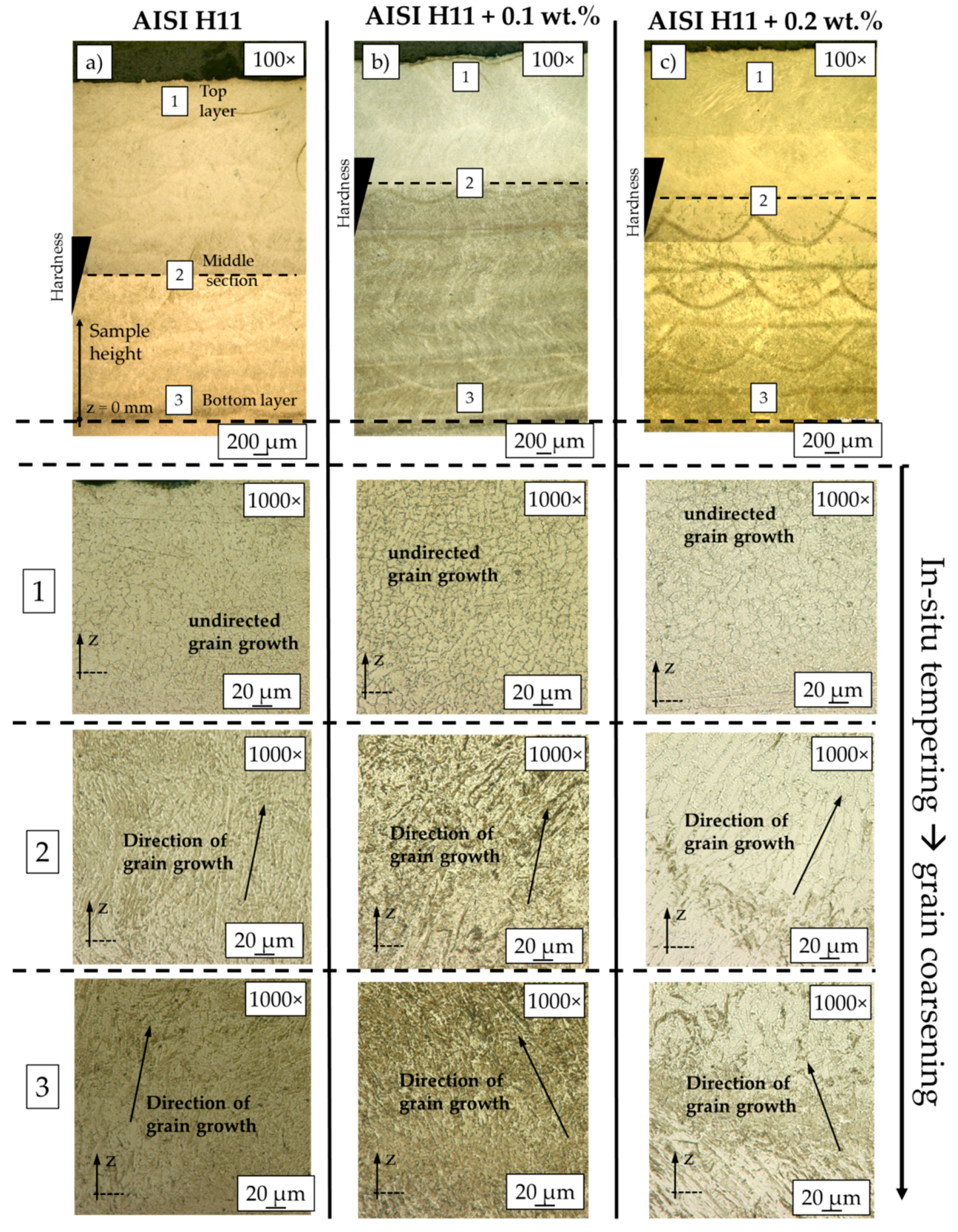
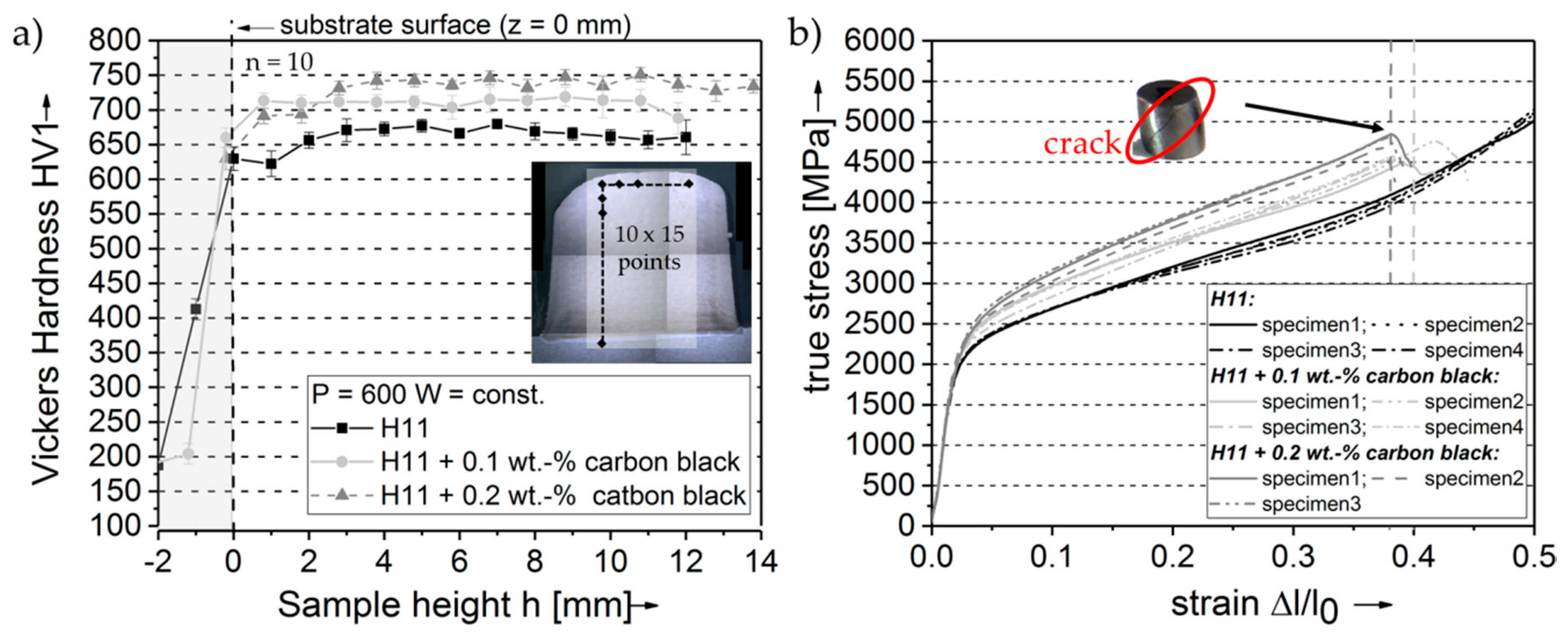
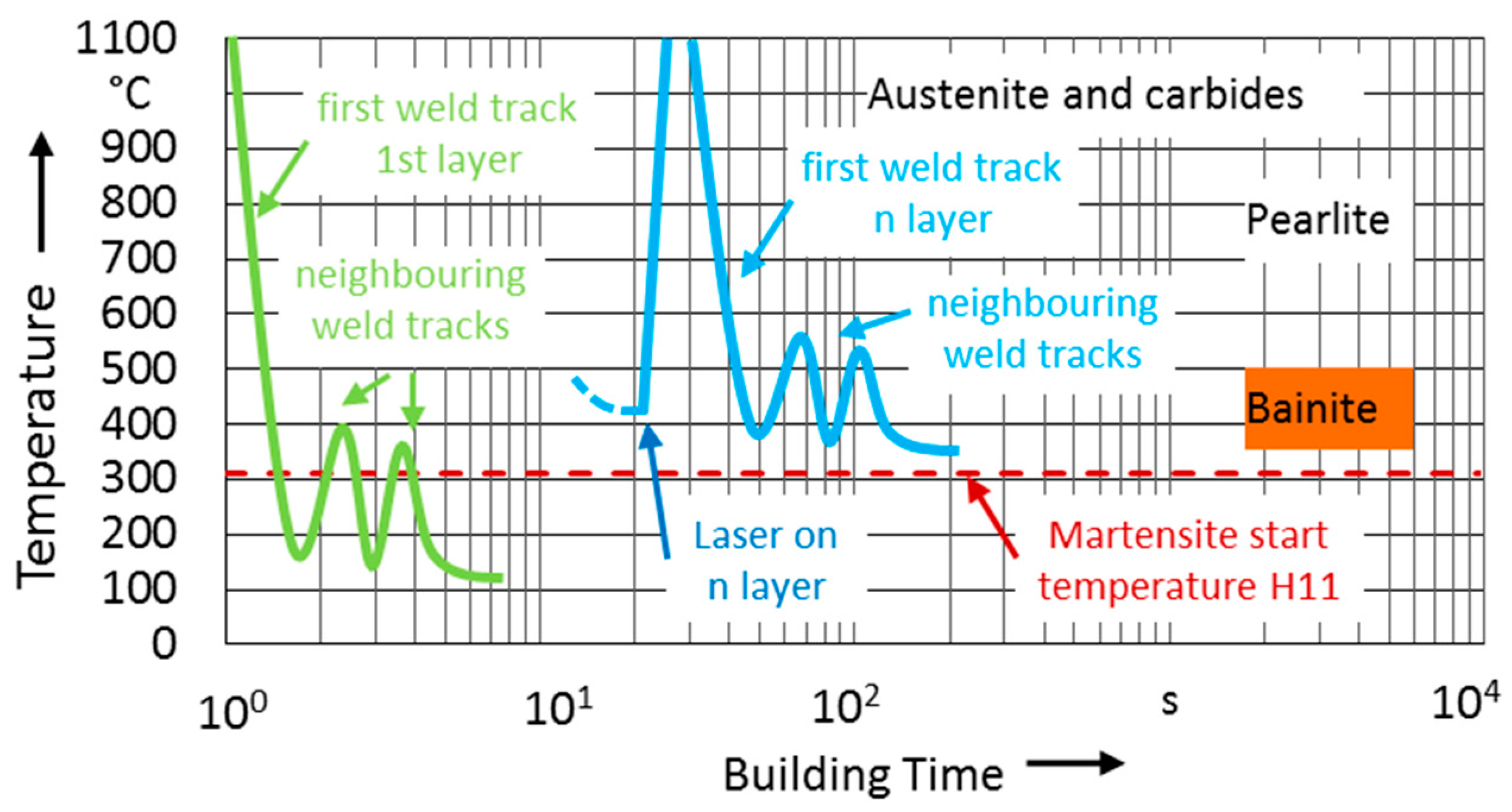
3.3. Influence of Nanoparticle Concentration on Microstructure and Hardness

As already mentioned above, for the evaluation of the microstructure, polished cross sections of four- and ten-layered samples were chemically etched using varying etching techniques, before analyzing the specimens by means of optical microscopy (see Section 2). In the following the results of these investigations are presented and discussed in detail.
As a consequence of the small melt pool volume and the process-inherent high cooling rates, a fine-grained and locally inhomogeneous microstructure is observed within the deposited material volume for both samples made out of AISI H11 powder as well as for those generated with the modified tool steel powder mixtures containing up to 0.2 wt. % nanoparticles.
In consideration of the time temperature transformation curve (TTT-curve) of both AISI H11 and similar tool steels with a slightly higher carbon content e.g., AISI H13 given by Reference [20] and the process-inherent rapid cooling and fast solidification of the generated melt pool, it is assumed that the microstructure of the samples mainly consists of both upper bainite containing fine ferrite needles enclosed by cementite (carbide network) and acicular martensitic phases (see comprehensive explanation in Appendix A and Figure A3). In contrast, the concentration of the residual austenite seems to be negligibly small due to the high process-inherent cooling rates and the inhomogeneous thermal history, which means the steady change between quick heating and rapid cooling during the LMD process. In order to verify these assumptions, the prepared cross sections were etched according to Beraha I [21] for the qualitative identification of the different metallurgical phases. Thereby, martensite and bainite appear as brown, green to blue structures in the microscope images and fine primary carbides are revealed as dark/black areas. On the contrary, larger chrome carbides and retained austenite are not affected by this etching technique and remain white or bright. Figure 10 shows the microstructure of a sample made out of the powder mixture containing 0.2 wt. % carbon nanoparticles with respect to the sample height. It can be seen that across the whole sample cross section martensitic and bainitic phases (brown, blue, and green colored areas) surrounded by a network of carbides (black and bright white areas) are present. In contrast to this, the concentration of residual austenite seems to be noticeably lower.
In general, the microstructure of samples made out of the pure AISI H11 powder and the modified powder mixtures looks very similar and at a first glance, there are no obvious microstructural differences discernable. However, by comparing the etched cross sections of pure AISI H11 samples and ones made out of the modified tool steel powder mixtures manufactured with the same set of process parameters (see Figure A4), it gives the impression that samples containing additional carbon black additives are more strongly affected by the Beraha I etchant as the pure tool steel specimens. This is reflected in a stronger blue coloring, which indicates an enhanced formation of martensite and bainite. However, to confirm these assumptions and to get a quantitative result of the remaining austenite and martensite/bainite, it is intended to perform Electron Back Scattering Diffraction (EBSD) or X-ray Diffraction (XRD) measurements within the scope of future research.
With a closer inspection of the microstructure with respect to the sample height, it is clearly discernible that the local microstructure mainly differs in size, shape and spatial orientation of the grains. Thereby, a finer grain structure in the upper areas, especially in the top layers, can be identified for all investigated samples regardless of the applied processing parameters and the added carbon black nanoparticle concentration (see Figure 10 and Figure 11). In the top layer the microstructure possesses a disordered character. Contrary to this, in the lower deposited layers the grains are preferably oriented in build-up direction as consequence of the epitaxial grain growth along the temperature gradients induced by the layer-by-layer manufacturing approach. Therefore, in these lower regions the microstructure predominately consists of columnar grains and partly dendritic structures.
The phenomenon of an inhomogeneous microstructure with respect to the sample height is also illustrated in Figure 11 for three samples made out of both the initial unmodified AISI H11 powder and tool steel powder mixtures with a carbon black nanoparticle content of 0.1 wt. % and 0.2 wt. %.
The carbides, which are surrounding the martensitic and bainitic phases, form a dense network threated through the whole sample. According to other authors, who have investigated the processing of the tool steel AISI H11 by LBM [24,25] and by LMD [13], these networks preferably consist of finely distributed chrome- and molybdenum-carbides. In order to verify this conclusion and to estimate the distribution of these main alloying elements (carbide formers), the samples were analyzed by means of EDX-area scanning (EDX-Mapping). Figure 12 shows the elemental distribution of chrome and molybdenum as false color images. The region of interest is located in the middle section of a specimen made out of the powder with an additional carbon black nanoparticle content of 0.2 wt. %.
As is qualitatively shown, the concentration of the carbide formers (chrome and molybdenum) at the grain boundaries, is enhanced. This indicates the occurrence of Cr and Mo- carbides in these regions. Furthermore, upon closer observation of the microscope images presented in Figure 10 and 11, it can be discerned that the carbide formers are more finely distributed in the top layer. The finer microstructure and close-meshed carbide network in the upper sections of the manufactured samples are the first indicators for a higher hardness in this region.
To validate this suspicion, highly spatially resolved hardness measurements were conducted on polished cross sections for samples with varying carbon nanoparticle content (see Figure 13a–d). In Figure 13b, the hardness profiles are plotted as a function of the sample height for ten-layered samples made out of various powder mixtures and manufactured with different laser powers. Regardless of the applied laser power and the type of processed powder mixture, an inhomogeneous hardness distribution is detected. Thereby, the hardness increases with the sample height.
Moreover, as expected, the hardness clearly rises with the concentration of added carbon nanoparticles (Figure 13b–d), because there is more carbon available for the formation of martensitic/bainitic phases and for the precipitation of carbides at the grain boundaries, whereby both mechanisms promote a high hardness and a promising mechanical strength.
According to Reference [13], which extensively investigated the microstructure of thin wall structures made out of stain less steel and AISI H13 tool steel, the resulting inhomogeneous hardness profile with respect to the sample height is a direct consequence of the layer-by-layer approach related to the additive manufacturing process. Thereby, the high hardness values of the top layers between 650 HV1 for the pure AISI H11 samples, about 730 HV1 for samples manufactured with 0.1 wt. % additional carbon black nanoparticles and around 790 HV1 for the samples made out the powder mixture with 0.2 wt. % nanoparticles can be theoretically explained by the process-inherent small melt pool volume, high cooling rates and rapid solidification of the melt pool and, related to this, the formation of the hardening and strengthening martensitic and bainitic phases. In contrast, the smaller hardness in the lower section is a consequence of tempering effects during the layer-by-layer manufacturing of the specimens. By the deposition of the upper layers the lower regions are annealed due to the laser-induced thermal energy and then transferred heat. In this way the lower sample regions are permanently kept at high temperatures, presumably close to the annealing temperature. This in situ heat-treatment (annealing) of the lower layers leads to a relaxation, reconfiguration and new-orientation of the microstructure and promotes the precipitation of carbides (preferably chrome carbides) at the grain boundaries as result of the induced diffusion processes (see Figure 10 and Figure 11 bottom layers). Furthermore, the in situ tempering causes grain coarsening, compare to Figure 10 and Figure 11. The superposition of these effects causes in the end a decrease of hardness in the lower regions resulting in the characteristic microstructure and the inhomogeneous hardness course with respect to the sample height.
The in situ annealing effect seems to be more pronounced with increasing laser power and the number of deposited weld track layers. An increase of both laser power as well as the number of deposited weld track layers results in a rise of the total laser-induced thermal energy and, therefore, an enhanced in situ tempering effect on the lower regions. Furthermore, an increase of the number of deposited weld track layers is equal to a rise of the tempering time dominating the observed in situ tempering effect. The comparison of the hardness profiles of samples composed of four and ten weld track layers emphasizes this relation (see Figure 13b–d). In contrast to the ten-layered samples, the four-layered samples possess a more or less consistent Vickers hardness as a function of the sample height.
Furthermore, it is clearly discernible in the measured hardness profiles presented in Figure 13b,c, that the in situ tempering effect and, related to that, the hardness difference between the top- and bottom-layer is enhanced with increasing carbon black nanoparticle content. The reason for this could be that the absorptivity of the powder increases due to the addition of carbon black nanoparticles. As a result, the total amount of laser-induced thermal energy input also increases, which leads to an enhancement of the in situ tempering.
However, to confirm this assumption both thermographic investigations of the manufacturing process for determining the melt pool temperature as well as calorimetric measurements with a similar experimental setup as suggested by Reference [22] to estimate the absorptivity of the powder with respect to the concentration of added nanoparticles are necessary.

3.4. Influence of the Nanoparticle Concentration on Compression Yield Strength and Ductility

To analyze the influence of the added carbon nanoparticles on the mechanical characteristics, compression tests were conducted. For that purpose, the experimental setup and procedure extensively described in Section 2 was used. All specimens were generated with the same set of process parameters (P = 600 W, m ˙ = 2.75 g/min, frate = 400 mm/min) in order to exclusively put the scientific focus on the effect of the nanoparticle concentration on the resulting compression yield strength. After the LMD process, the cuboid-shaped specimens consisting of 35 layers were firstly heat-treated and subsequently analyzed with respect to the microstructure and hardness.

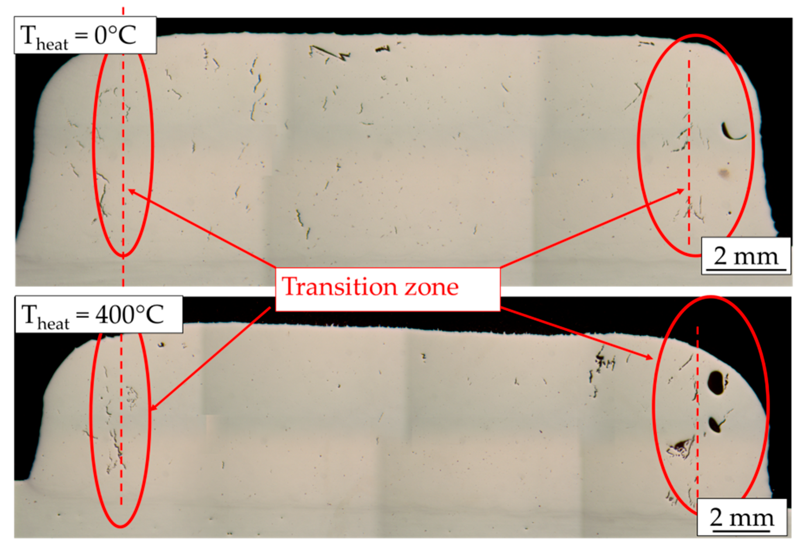
3.4.1. Influence of Post-Heat-Treatment on Microstructure and Hardness Distribution

Due to the high hardness of the manufactured samples in the as-built conditions, which is an indicator for high mechanical strength, it was decided to omit the initial hardening step consisting of austenitization at around 1080 °C followed by quenching as it is used for conventionally manufactured parts made out of AISI H11. Instead, the post-heat-treatment was limited to a single tempering (annealing) of the samples at a constant temperature of about 550 °C for 2 h under ambient atmosphere in a commercially available chamber kiln. In this manner, process-inherent residual stresses can decrease on a moderate level and, related to this, the ductile character of the specimens is enhanced. At the same time hardness should be retained as high as possible.
Figure 14a–c above shows the microstructure of an annealed sample manufactured with the tool steel powder mixture containing 0.2 wt. % carbon black nanoparticles. As a consequence of the induced diffusion processes, a relaxation and reconfiguration of the microstructure could be achieved leading to a more or less homogenous microstructure with respect to the sample height. In this way, the hardness difference between the lower regions and the top layer of the samples can be eliminated to a great extent. Only in the bottom layers is the hardness still slightly lower for both the pure tool steel samples and the ones made out of the modified tool steel powders (see Figure 15a).
As it was the case for the non-heat-treated samples, the hardness is still noticeably affected by the concentration of initially added nanoparticles. After the post annealing procedure, the hardness of the samples generated with 0.1 wt. % and 0.2 wt. % additional carbon black nanoparticles slightly decreases. Thereby, a hardness mean value of about 730 HV1 was measured for the sample manufactured with the tool steel powder mixture containing 0.2 wt. % additional nanoparticles, whereas a mean value of about 705 HV1 for the sample made out of the tool steel powder mixture with 0.1 wt. % additives.
On the contrary, the hardness of the pure tool steel sample increases slightly from on average value of 650 HV1 to about 660 HV1 compared to the as-built state. The observed increase in hardness presumably results from the decomposition of residual austenite and the precipitation of secondary carbides (primarily chrome carbides) at the grain boundaries. However, the resulting average hardness of the pure AISI H11 sample is still lower as for annealed samples fabricated with the modified powder mixtures.
After the heat-treatment the final cylindrical compression specimens were mechanically treated by milling, cutting and circular grinding. In this context, the softer bottom part of the samples was not taken into account in order to prevent compression specimens with inhomogeneous hardness distribution promoting a strong anisotropic forming behavior of the compression specimens (see Figure 14a).

3.4.2. Influence of the Nanoparticle Concentration on Compression Yield Strength and Ductility

In the following, the yield strength Y0.2% and the compression stress Y30% at a strain of 30% evaluated on the basis of stress-strain curves of the specimens are shown and discussed in detail. Table 4 shows the determined mean values of yield strength Y0.2% and compression stress Y30% for the analyzed specimens with the calculated standard deviations.
For the specimens made out of the pure, unmodified hot-work tool steel powder, the mean value of the compression yield strength is about 1942 ± 12 MPa. In contrast to Reference [11], which determined the compression yield strength of pure AISI H11 specimens manufactured by LMD after conventional heat-treatment consisting of austenitization and quenching followed by three-time annealing to about 1650 MPa, the values achieved for the annealed AISI H11 specimens are significantly enhanced. This indicates that a modification and adaption of the post-heat-treatment strategy with respect to the microstructural properties of additively manufactured parts seems to be an adequate way to achieve outstanding mechanical properties.
Furthermore, the yield strength significantly increases with the amount of added carbon nanoparticles. For samples manufactured with an additional carbon black nanoparticle content of 0.1 wt. % the mean yield strength takes a value of 2116 ± 3 MPa. This corresponds to an increase in strength of about 9.2% in comparison to the annealed pure tool steel samples. The maximum yield strength directly correlates with the concentration of added nanoparticles and is observed for the specimens with 0.2 wt. % additives. In this case the mean value of the compression yield strength is about 2181 ± 32 MPa. By contrast with specimens made out of pure tool steel powder this is equivalent to an increase in strength of around 11%.
As the purpose of forging tools is to resist the huge dynamical load during the forming of bulk metal, high yield strength and high hardness are very important properties of the material used for tools. On the other hand, the material should not be too brittle in order to avoid cracking during the forming process when the tool is exposed to high dynamical loads. To evaluate and verify the influence of the additional carbon black content on the ductility, the determined strain-stress curves of the specimens presented in Figure 15b are studied more in detail. Analyzing the stress-strain curves, all specimens show a strong strain. Regardless of the tested specimen the true stress steeply rises in the beginning and can reach values up to a maximum of 5000 MPa at a strain of 50% for specimens generated with pure AISI H11 powder. The characteristic steep rising to the high true stress results from strain hardening effects. In consideration of the mean values of the compression stress at 30% strain, which are presented in Table 4, and the slopes of the stress-strain curves in the region of plastic forming, it is obvious that the strain hardening effect is enhanced with increasing concentration of added carbon black nanoparticles.
In contrast to the pure tool steel samples, the specimens made out of the modified tool steel powder mixtures could not be compressed to 50% of their initial height without fracture. The samples with 0.1 wt. % additional carbon black nanoparticles burst at a strain of around 40% and the samples with the maximum nanoparticle concentration of 0.2 wt. % at around 38%.
Consequently, at this point it can be highlighted that the addition of carbon black nanoparticles leads to a noticeable increase of the yield strength/mechanical strength. In contrast the ductility seems to be slightly lowered by the modification of the initial tool steel powder with carbon black nanoparticles. However, a further adaption of the post-heat-treatment parameters and strategy (e.g., annealing temperature, tempering time or multiple annealing) could be a possibility to further improve the ductility of these materials and simultaneously to retain high hardness and mechanical strength.

3.5. Graded Structure with Layer-Specific Variable Hardness

One of the outstanding characteristics of the LMD process, compared to other laser-based additive manufacturing technologies, is the fast and flexible way in which the processed material during the layer-by-layer manufacturing of parts may be changed. In this manner, parts with spatial or at least layer-specific variable properties—so-called multi-material parts or graded structures—can be generated. Expecting that a different concentration of carbon in the single weld track layers results in a layer-wise variation of hardness and associated with a layer-by-layer adaption of mechanical strength, we investigated generating a cuboid sample with a defined gradual hardness increase in build-up direction by changing the used powder in the varying weld track layers. The desired cascaded hardness profile with respect to sample height is schematically shown in Figure 16a. For that purpose, a cuboid-shaped sample consisting of two bottom layers of pure AISI H11 followed by five layers made out of AISI H11 powder with 0.1 wt. % additional carbon black and five layers made out of powder mixture with 0.2 wt. % added nanoparticles was generated. Figure 16b illustrates the explained manufacturing scheme by means of a microscope image of the etched sample cross section. For manufacturing the graded sample, the laser power was permanently set to 600 W and the powder mass flow was adjusted to a constant value of 2.75 g/min for all processed powder mixtures.
After the manufacturing, the sample was prepared and analyzed according to the experimental procedure explained in Section 2, whereby the focus was put on the resulting hardness distribution. The manufactured graded sample possesses a high relative density with a remaining porosity smaller than 0.5%. Furthermore, the sample is free from larger defects, e.g., irregular-shaped voids or inclusions (metal oxides) promoting an enhanced notch effect under dynamical load. As could be verified by the microscopic analysis of the polished cross section, the remaining mainly circular pores have a small average pore size in the order of 20 µm.
The microstructure of the graded sample looks at first glace very similar to the resulting inner structure observed for the ten-layered samples made out of only one certain powder mixture. Thereby, the upper layers show a finer microstructure than the middle and bottom sections of the sample, which are affected by grain coarsening resulting from the previously described in situ tempering effect (see Figure 16b).
Figure 17a shows the measured hardness profiles of the graded sample in the as-built state as a function of the sample height h. For comparative purposes the hardness profiles of the ten-layered samples manufactured with the same set of process parameters are also presented.
Analyzing the hardness profile of the graded sample in the as-built state, a clear cascaded increase of the hardness with respect to the sample height can be observed. This characteristic rise of hardness can directly be correlated to the different powder mixtures and associated with to the varying amount of added carbon black nanoparticles. The five top layers made out of the AISI H11 powder with the maximal nanoparticle content of 0.2 wt. % possess a very fine-grained microstructure and the average Vickers hardness is determined to about 800 HV1. The hardness drops to a mean value of about 630 HV1 within the four layers generated with the powder mixture containing 0.1 wt. % additional carbon black nanoparticles and reaches a minimum mean value of about 550 HV1 in the two bottom layers made out of the unmodified tool steel. By taking the in situ tempering effect promoting a hardness decrease in the middle and bottom section of the generated sample into account, the resulting hardness profile of the generated graded structure is in good approximation with the desired cascaded hardness distribution illustrated in Figure 16a. A comparison of the hardness profiles of the graded structure with the hardness profiles of samples made out of only one specific tool steel powder mixture supports this conclusion (see Figure 17a).
In Figure 17b the resulting hardness profiles of the graded sample in both the as-built state and after the annealing process are plotted as a function of the sample height. By closer consideration of the hardness profile of the sample in the annealed state, it is evident that the annealing of the sample leads to a modification of the layer-specific hardness. Furthermore, the hardness difference between the three characteristic regions within the sample becomes notably smaller. After the heat-treatment a clear step-like increase of the hardness in the order of about 70 HV1 is only identifiable at the transition between the top section (AISI H11 + 0.2 wt. % carbon black nanoparticles) and the middle section (AISI H11 + 0.1 wt. % carbon black nanoparticles) of the sample. On the contrary, the stepped hardness increases between the tool steel bottom layer and the middle section—consisting of layers made out of AISI H11 powder with 0.1 wt. % nanoparticle additives—is transformed into a smoother, approximately steady/continuous increase.
At this point it can be summarized that it is principally possible to manufacture graded tool steel structures with layer-specific hardness by the presented approach. However, post-heat-treatment noticeably changes the course of the desired cascaded hardness profile in build-up direction.

4. Conclusions and Outlook

In the presented approach, the processing of the hot-work tool steel AISI H11 modified by adding carbon black nanoparticles in varying concentrations by means of LMD was analyzed in detail. The investigations show, that defect-free cuboid-shaped samples with a remaining porosity smaller than 0.5% can be generated on the basis of the prepared tool steel/carbon black powder mixtures. Up to carbon black nanoparticle concentration of 0.2 wt. % no significant differences in the processability (weldability) of the modified tool steel powder mixtures in comparison to the pure tool steel powder are identifiable. However, with an increase in the concentration of the added carbon black nanoparticles the susceptibility to cracking is dramatically enhanced and the process ability becomes poor. Even an additional pre-heating of the substrate to a temperature level of the martensite start temperature simultaneously to the LMD process in order to reduce process-inherent thermal stresses cannot completely prevent the formation of cracks during the manufacturing of volumetric, multi-layered samples.
As demonstrated by means of spatially resolved hardness measurements and compression tests, the addition of small quantities of nanoparticles in the order of 0.1 wt. % and 0.2 wt. % significantly increase the hardness and yield strength in comparison to pure AISI H11. Thereby, a maximal percentage increase of yield strength of about 11% could be achieved by adding 0.2 wt. % carbon nanoparticles to the initial tool steel powder. In contrast, the ductility of specimens manufactured on the basis of the modified tool steel powder mixtures slightly decrease compared to samples made out of the pure AISI H11 powder. The observed increase of the mechanical strength and slight decrease of ductility seems to be the direct consequence of the added carbon black nanoparticles promoting an enhanced formation of hardness- and strength-increasing bainitic and martensitic phases within the deposited material volume.
Furthermore, it could be fundamentally demonstrated that the fabrication of parts with layer-specific variable hardness can be realized by the controlled changing of the used tool steel powder mixture during the layer-by-layer manufacturing.
Within the scope of future research it is intended to optimize both the preheating and the deposition strategy in order to process tool steel powder mixtures with a carbon black nanoparticle content larger than 0.2 wt. % to nearly fully dense and crack-free volumetric samples. Furthermore, it is planned to investigate the processing of these modified tool steel powder mixtures by means of thermography and high-speed camera analysis. In this manner, an in-depth understanding of the influence of the added nanoparticle concentration on the maximal melt pool temperature, the cooling- and solidification behavior as well as the process dynamics (melt pool dynamic) can be achieved. Apart from that, the effect of the added carbon black nanoparticles on the absorptivity will be characterized by means of calorimetric measurements using an experimental setup similar to that described in Reference [22].
On the basis of these fundamental investigations, process strategies for the manufacturing of complete forging tools made out of these modified tool steel powder mixtures will be developed. Subsequently, these tools will be characterized under conditions being close to industrial use.
Furthermore, the effect of other nanoparticle species, e.g., tungsten carbide particles, on the resulting microstructural and mechanical properties will be object of extended scientific investigations.

Author Contributions

O.H. prepared the design of experiments. He manufactured together with L.S. the samples and coordinated the metallographic preparation and analysis of the manufactured samples. Furthermore, he was responsible for writing the paper. L.S. supported the manufacturing of the samples and prepared the metallographic cross sections. Apart from that, he took part in the experimental characterization of the prepared cross sections. C.S. and F.H. contributed to the microstructural analysis and the hardness measurements. Furthermore, C.S. proofread the manuscript. D.J. conducted the compression test of manufactured samples at the Institute of Manufacturing Technology. A.G. supported the experimental characterization of the generated samples with the focus on microstructure-related aspects. M.S. supervised the work.

Funding

The work was performed with the kind support of the School of Advanced Optical Technology (SAOT) of the University Erlangen-Nürnberg and the Ministry of Education and Science of the Russian Federation, decree N220, state Contract No. 14.Z50.31.0023.

Acknowledgments

In addition, the authors want to thank Andreas Haimerl of the Schaeffler Technologies AG & Co. KG for conducting the chemical analysis of the initial AISI H11 tool steel powder and Andreas Rottmann of the FAG Aerospace GmbH & Co. KG for analyzing manufactured samples by means of optical emission spectroscopy.

Conflicts of Interest

The authors declare no conflicts of interest.

Appendix A

Figure A1. Relative density ρrel of samples made out of pure AISI H11 and the modified powder mixtures as a function of laser power and with respect to the applied powder mass flow (determined on the basis of three analyzed planes per sample).
Metals 08 00659 g0a1
Figure A2. Cracks and microstructure in the core region of a cracked sample containing 0.5 wt. % carbon black nanoparticles manufactured without additional pre-heating (etching method V2A).
Metals 08 00659 g0a2
An indirect proof for the existence of bainite and martensite can also be drawn considering the thermal history of the specimen during the layer-by-layer build-up process. Due to high cooling rates, which result from the deposition on a cold substrate at ambient temperature and from the small melt pool volume, the liquid metal within the first layer turns to martensite immediately (see green curve in Figure A3). Because of the continuous layer-by-layer build-up process (in situ tempering), the temperature of the specimen constantly increases, reaching a level above the martensite start temperature after a certain build height (see blue curve in Figure A3). Consequently, the next layers cannot transform to martensite. In this context, the quasi-stationary temperature field highly depends on the applied processing parameters and build-up strategy. As the material can just reach temperatures, which are above the martensite start temperatures, during rapid solidification and cooling phase, the formation of bainite might very likely occur (see TTT-curves for ASIS H11 [20] or Figure A3). After the manufacturing process, the whole sample homogeneously cools down at a rate at which one might not expect significant further changes of the microstructure.
Figure A3. Schematic illustration of time-temperature-transformation curve for the first weld tracks at certain layers with microstructure-related aspects inspired by Reference [20].
Metals 08 00659 g0a3
Figure A4. Microscope images of the local microstructure (top layer, middle section and bottom layer) of ten-layered sample made out of pure AISI H11 (left) and a powder mixture containing 0.2 wt. % carbon black nanoparticles (right) (etching method Behara I; process parameters: P = 600 W, m ˙ = 2.7   g / min , frate = 400 mm/min).
Metals 08 00659 g0a4

References

  1. Kelbassa, I. Qualifizieren des Laserstrahl-Auftragsschweißen von BLISKs aus Nickel-und Titanbasislegierungen, Dissertation; RWTH: Aachen, Germany, 2006; Available online: http://publications.rwth-aachen.de/record/60728/files/Kelbassa_Ingomar.pdf (accessed on 22 August 2018).
  2. Majumdar, J.D.; Manna, I. Laser-Assisted Fabrication of Materials; Springer Series in Material Science 161; Springer: Berlin/Heidelberg, Germany, 2013. [Google Scholar]
  3. Weisheit, A.; Fuchs, E.; Bankowski, M.; Freyer, C. Multifunktionale Gradientenwerkstoffe für den Werkzeugbau; BMBF-Abschlussbericht: Aachen, Germany, 2006; p. 301. [Google Scholar]
  4. Toyserkani, E.; Khajepour, A.; Corbin, S. Laser Cladding; CRC Press: New York, NY, USA, 2005. [Google Scholar]
  5. Scheitler, C.; Hentschel, O.; Krebs, T.; Nagulin, K.; Schmidt, M. Laser metal deposition of NiTi shape memory alloy on Ti sheet metal: Influence of preheating on dissimilar build-up. J. Laser Appl. 2017, 29, 022309. [Google Scholar] [CrossRef] [Green Version]
  6. Mazumder, J.; Dutta, D.; Kikuchi, N. Closed-loop direct metal deposition. Opt. Lasers Eng. 2000, 34, 397–414. [Google Scholar] [CrossRef]
  7. Junker, D.; Hentschel, O.; Schmidt, M.; Merklein, M. Qualification of Laser Based Additive Production for Manufacturing of Forging Tools. In Proceedings of the 4th International Conference on New Forming Technology (ICNFT 2015), Glasgow, UK, 6–9 August 2015. [Google Scholar]
  8. Karg, M.; Hentschel, O.; Ahuja, B.; Junker, D.; Haßler, U.; Haimerl, A.; Arnet, H.; Merklein, M.; Schmidt, M. Comparison of process characteristics and resulting microstructures of maraging steel 1.2709 in Additive Manufacturing via Laser Metal Deposition and Laser Beam Melting in Powder Bed. In Proceedings of the 6th International Conference on Additive Technologies, Nürnberg, Germany, 29–30 November 2016. [Google Scholar]
  9. Schmidt, M.; Merklein, M.; Borell, D.; Dimitrov, D.; Hausotte, T.; Wegener, K.; Overmeyer, L.; Vollertsen, F.; Levy, G.N. Laser based additive manufacturing in industry and academia. CIRP Ann. 2017, 66, 561–583. [Google Scholar] [CrossRef]
  10. Freiße, H.; Khazan, P.; Stroth, M.; Köhler, H. Properties of large 3D parts made From Stellite 21 through direct powder deposition. In Proceedings of the Laser in Manufacturing Conference, Munich, Germany, 22–25 June 2015. [Google Scholar]
  11. Junker, D.; Hentschel, O.; Schramme, R.; Schmidt, M.; Merklein, M. Performance of Hot Forging Tools built by Laser Metal Deposition of Hot Work Tool Steel X37CrMoV5-1. In Proceedings of the Laser in Manufacturing 311 Conference, Munich, Germany, 26–29 June 2017. [Google Scholar]
  12. Telasang, G.; Majumdar, J.D. Effect of laser parameters on microstructure and hardness of laser clad and tempered AISI H13 tool steel. Surf. Coat. Technol. 2014, 258, 1108–1118. [Google Scholar] [CrossRef]
  13. Hofmeister, W.; Griffith, M.; Ensz, M.; Smugeresky, J. Solidification in Direct Metal Deposition by LENS Processing; Laser Processing Overview. JOM 2001, 53, 30–34. [Google Scholar] [CrossRef]
  14. Hentschel, O.; Scheitler, C.; Fedorov, A.; Junker, D.; Gorunow, A.; Haimerl, A.; Merklein, M.; Schmidt, M. Experimental investigation of processing the high carbon cold-work tool steel 1.2358 by LMD for the additive manufacturing of cold forging tools. J. Laser Appl. 2017, 29, 022307. [Google Scholar] [CrossRef]
  15. Karg, M.; Ahuja, B.; Schmidt, J.; Winzer, B.; Wirth, K.E.; Peukert, W.; Schmidt, M. Laser Beam Melting in Powder Bed of nonspherical aluminium microparticles dry coated with metal nanoparticles. In Proceedings of the 6th International Conference on Additive Technologies, Nürnberg, Germany, 29–30 November 2016. [Google Scholar]
  16. Gu, D.; Wang, H.; Chang, F.; Dai, D.; Yuan, P.; Hagendorn, Y.C.; Meiners, W. Selective Laser Melting of TiC/AlSi10Mg Bulk-form Nanocomposites with Tailored Microstructures and Properties. Phys. Procedia 2014, 56, 108–116. [Google Scholar] [CrossRef]
  17. Martin, J.H.; Yahata, B.; Mayer, J.; Schaedler, T.; Pollock, T.M. 3D printing of high-strength aluminium alloys. Nat. Int. J. Sci. Lett. 2017, 549, 365–369. [Google Scholar] [CrossRef] [PubMed]
  18. Bischof, C.; Nitsch, G.; Scheitler, C.; Dressler, A.; Schmidt, M. Laser beam melting of water atomized iron base alloy FE-4800 WITH in-situ alloying of carbon nanoparticles. In Proceedings of the 17th Annual Conference of the Rapid Product Development Association of South Africa, Pretoria, South Africa, 2–4 November 2016. [Google Scholar]
  19. Gu, D.; Sainan, C.; Kaijie, L. Laser metal deposition manufacturing of TiC reinforced Inconel 625 composites: Influence of the additive TiC particle and its starting size. J. Manuf. Sci. Eng. 2016, 139, 041014. [Google Scholar] [CrossRef]
  20. Wegst, M.; Wegst, C. Stahlschlüssel—Key to Steel 2016: Nachschlagewerk Dt./Engl./Franz; Stahlschlüssel-Verlag: Marbach, Germany, 2013. [Google Scholar]
  21. Vander Voort, G.F. Matallography, Principles and Practice; ASM International: Materials Park, OH, USA, 1999; ISBN 978-0-87170-672-0. [Google Scholar]
  22. With, F.; Eisenbarth, D.; Wegener, K. Absorptivity measurements and heat source modeling to simulate laser cladding. Phys. Procedia 2016, 83, 1424–1434. [Google Scholar]
  23. Mayer, S.; Scheu, C.; Leitner, H.; Clemens, H.; Siller, I. Influence of the Cooling Rate on the Mechanical Properties of a Hot-work Tool Steel. Berg- und Hüttenmännische Monatshefte 2007, 152, 132–136. [Google Scholar] [CrossRef]
  24. Over, C. Generative Fertigung von Bauteilen aus Werkzeugstahl X38CrMoV5-1 und Titan TiAl6V4 mit “Selective Laser Melting”; RWTH Aachen: Aachen, Germany, 2003; ISBN 3-8322-2245-6. [Google Scholar]
  25. Jansen, S. Generative Fertigung von Konturnah Temperierten Werkzeugen Mittels Selective Laser Melting; RWTH Aachen: Aachen, Germany, 2014; ISBN 978-3-86359-183-0. [Google Scholar]
Figure 1. (a) Simplified illustration of the Laser Metal Deposition (LMD) process with three-way powder nozzle (b) LMD setup with additional substrate pre-heating device to reduce internal stresses.
Metals 08 00659 g001
Figure 2. SEM images of the (ac) unsieved AISI H11 powder (magnifications: 500×, 5000×, and 10,000×, respectively) and (df) of the carbon black nanoparticles (magnifications: 500×, 10,000× and 50,000×, respectively).
Metals 08 00659 g002
Figure 3. SEM images of modified tool steel powder mixtures containing (a) 0.3 wt. % and (b) 0.5 wt. % carbon black nanoparticles (from left to right, magnifications: 250×, 5000× and 10,000×, respectively).
Metals 08 00659 g003
Figure 4. Experimentally determined powder mass flow of prepared powder mixture and pure AISI H11 powder with respect to rotation per minute (rpm) of the dosing plate.
Metals 08 00659 g004
Figure 5. (a) Etched cross section of a single weld track (P = 1 kW, m ˙ = 3.7   g / min ) and (b) cuboidal samples made out of AISI H11 with 0.2 wt. % additional carbon nanoparticles with varying numbers n of deposited weld track layers (P = 800 W, m ˙ = 3.7   g / min , frate = 400 mm/min).
Metals 08 00659 g005
Figure 6. Weld track (a,b) width, (c,d) height and (e,f) depth of the dilution zone of single weld tracks as a function of laser power and for a powder mass flow of 2.7 ± 0.1 g/min and 3.7 ± 0.1 g/min.
Metals 08 00659 g006
Figure 7. Powder catchment efficiency of single weld tracks deposited with the analyzed tool steel powder mixtures as a function of laser power and a powder mass flow of 2.7 g/min (left) and 3.7 g/min (right).
Metals 08 00659 g007
Figure 8. Polished metallographic cross sections of samples manufactured with the pure AISI powder and the modified tool steel powder mixtures with respect to the total carbon content (P = 800 W, m ˙ = 2.7   g / min , frate = 400 mm/min).
Metals 08 00659 g008
Figure 9. Polished cross sections of samples made out of tool steel powder mixtures with 0.5 wt. % nanoparticles manufactured without (above) and with (below) additional substrate pre-heating (Theat = 400 °C).
Metals 08 00659 g009
Figure 10. Microscope images of the local microstructure (top layer, middle section and bottom layer) of a ten-layered sample containing 0.2 wt. % carbon black nanoparticles (etching method Behara I; process parameters: P = 800 W, m ˙ = 3.7   g / min , frate = 400 mm/min).
Metals 08 00659 g010
Figure 11. Microscope images of the local microstructure (top layer, middle section and bottom layer) of a ten-layered sample made out of (a) pure AISI H11, (b) AISI H11 + 0.1 wt. % and (c) H11 + 0.2 wt. % carbon black nanoparticles (V2A etchant; process parameters: P = 600 W, m ˙ = 2.75 g/min, frate = 400 mm/min).
Metals 08 00659 g011
Figure 12. (a) Microscope image of etched cross-section (V2A etchant) and EDX-mapping/element distribution of (b) Fe, (c) Cr and (d) Mo (processing parameters: P = 800 W, m ˙ = 3.7   g / min , frate = 400 mm/min) .
Metals 08 00659 g012
Figure 13. (a) distribution of hardness measurement points over the cross section of four- and ten-layered sample (H11 + 0.2 wt. % carbon black: P = 600 W, m ˙ = 3.7 g/min); Hardness profiles of samples made out of the investigated tool steel powders as function of the sample height h with respect to laser power: (b) 10-layered samples at m ˙ = 2.7 g/min, (c) 10-layered samples with different powder mass flows and (d) 4-layered samples.
Metals 08 00659 g013
Figure 14. Microscope images of etched cross sections after annealing for a sample made out of H11 powder containing 0.2 wt. % nanoparticle additives: (a) complete cross section, (b) in the region of homogenous microstructure and constant hardness (1000×) and (c) in the softer lower region (1000×) (etching method: V2A).
Metals 08 00659 g014
Figure 15. (a) Hardness profiles as function of the sample height for 35-layered samples after annealing and prior to the mechanical finishing and (b) stress-strain curves of the tested specimens.
Metals 08 00659 g015
Figure 16. (a) Idealized illustration of the desired hardness profile with respect to the sample height and the concentration of added carbon black nanoparticles; (b) local microstructure of the graded sample with respect to the sample height in varying magnifications (magnifications: 100×, 1000×).
Metals 08 00659 g016
Figure 17. (a) Hardness distribution of the graded sample and of samples manufactured with 0.1 wt. % and 0.2 wt. % additional carbon black nanoparticles, (b) Hardness distribution of the graded sample in the as-built state and after annealing.
Metals 08 00659 g017
Table 1. Chemical composition of AISI H11 powder and AISI H11 substrate.
MaterialC (wt. %)Si (wt. %)Cr (wt. %)Mo (wt.%)V (wt. %)
AISI H11 powder0.350.985.161.290.47
Substrate plates0.390.95.091.290.33
Reference [20]0.33–0.410.9–1.24.8–5.51.1–1.40.25–0.5
Table 2. Sets of process parameters used for single weld track experiments and the manufacturing of volumetric samples.
Laser Power
P (W)
Powder Mass Flow
m ˙     ( g / min )
Feed Rate
frate (mm/min)
Transport Gas
V ˙ H e   ( L / min )
Protection Gas
V ˙ A r   ( L / min )
600–10002.7 ± 0.1; 3.7 ± 0.1400820
Table 3. Chemical composition of selected ten-layered samples with respect to the laser power and the added nanoparticle content ( m ˙ = const. = 3.7 ± 0.1 g/min, frate = 400 mm/min).
MaterialsP (W)C (wt. %)Cr (wt. %)Mo (wt. %)V (wt. %)
AISI H11 powder-0.355.361.290.47
AISI H116000.34 ± 0.015.371.230.46
10000.33 ± 0.0155.341.270.45
AISI H11 + 0.1 wt. %6000.40 ± 0.015.311.240.44
10000.41 ± 0.025.351.260.42
AISI H11 + 0.2 wt. %6000.47 ± 0.015.381.220.48
10000.46 ± 0.025.351.270.43
Reference AISI H11 [20]-0.33–0.414.8–5.51.1–1.40.25–0.5
Table 4. Compression Yield strength Y0.2% and compression stress Y30% at 30% strain.
MaterialYield Strength Y0.2% (MPa)Stress Y30% (MPa)
AISI H11 (n = 4)1942 ± 123638 ± 48
AISI H11 + 0.1 wt. % carbon black (n = 4)2116 ± 34023 ± 50
AISI H11 + 0.2 wt. % carbon black (n = 3)2181 ± 324327 ± 49

