Article

The Aqueous Electrochemical Response of TiC–Stainless Steel Cermets

Department of Mechanical Engineering, Materials Engineering Programme, Dalhousie University, 1360 Barrington Street, Halifax, NS B3H 4R2, Canada
*
Author to whom correspondence should be addressed.
Metals 2018, 8(6), 398; https://doi.org/10.3390/met8060398
Submission received: 5 March 2018 / Revised: 27 April 2018 / Accepted: 23 May 2018 / Published: 30 May 2018
(This article belongs to the Special Issue Cermets and Hardmetals)

Abstract

:
A family of TiC–stainless steel ceramic–metal composites, or cermets, has been developed in the present study, using steel grades of 304 L, 316 L, or 410 L as the binder phase. Melt infiltration was used to prepare the cermets, with the steel binder contents varying between 10–30 vol. %. The corrosion behaviour was evaluated using a range of electrochemical techniques in an aqueous solution containing 3.5 wt. % NaCl. The test methods included potentiodynamic, cyclic, and potentiostatic polarisation. The corroded samples were subsequently characterised using scanning electron microscopy (SEM) and energy dispersive X-ray spectroscopy (EDS), while the post-corrosion solutions were analysed using inductively coupled plasma optical emission spectroscopy (ICP-OES) to determine the residual ionic and particulate material removed from the cermets during electrochemical testing. It was demonstrated that the corrosion resistance was enhanced through decreasing the steel binder content, which arises due to the preferential dissolution of the binder phase, while the TiC ceramic remains largely unaffected. Increasing corrosion resistance was observed in the sequence TiC-304 L > TiC-316 L > TiC-410 L.

1. Introduction

Titanium carbide (TiC)-based ceramic-metal composites, or cermets, have become more widely used in demanding wear applications due to their improved capabilities when compared with more traditional “hardmetals” based on tungsten carbide with a cobalt binder (WC-Co) [1]. TiC-based cermets have several properties that typically exceed those of WC, such as increased hardness and toughness, as well as a lower mass; the density of WC is approximately three times that of TiC [2]. Therefore, these characteristics offer the potential for TiC-based cermets to replace WC-Co in a variety of industrial applications. For example, it has been shown that TiC-based cermets can exhibit sliding wear resistance comparable to or even exceeding that of WC-Co [3,4,5].
In terms of cermet corrosion behaviour, it is invariably noted that the incorporation of a metallic binder with the ceramic matrix phase degrades the performance [6,7,8,9,10,11,12,13,14,15,16,17,18,19,20]. In this instance, the binder metallic phase has been noted to affect corrosion through its selective dissolution, while the ceramic phase remains relatively immune. Monticelli et al. reported a loss in corrosion resistance through the incorporation of Co binder into WC for thermal spray coatings [18]. By comparing the corrosion performance of “pure” WC and WC prepared with 5 wt. % Co, the corrosion resistance of the WC-Co materials decreased, which was attributed to the preferential dissolution of the Co binder in the composite. Other authors have also reported evidence of dissolution of the Co binder [7,10], and it was confirmed that the loss of the metal binder governs the corrosion behaviour of WC-Co cermets, although it is also dependent upon the applied potential. The corrosion resistance of WC-Co also decreases with an increase in Co binder content, as noted by Sutthiruangwong et al. [8], who also showed an improvement in the corrosion resistance of cermets with a higher dissolved WC content in the Co binder.
Cermets are often used in coating form to reduce the wear and, potentially, the corrosion of metallic components. These coatings typically consist of WC or chromium carbide (Cr3C2) particles embedded in a metal binder, which can be a pure metal or an alloy, for example consisting of a mixture of Ni, Cr, and/or Co [21]. As many coatings have complex compositions, and multiple components, the possibility of microgalvanic corrosion activity between the different constituents can arise, which is likely to undermine the surface integrity of the coating [21]. As an example, the presence of carbides in a metallic binder typically improves wear resistance, but at the same time may establish a microcorrosion cell at the carbide–metal interface. This can arise as the carbide is likely to be more cathodic in character with respect to the surrounding metallic matrix, leading to the possibility of a preferential anodic dissolution of the metallic matrix close to, or at, the matrix–carbide interface. Consequently, carbide removal from the surface can be accelerated due to loss of the retaining metallic binder; hence, there is a reduction of the wear-resistant properties [22]. Such behaviour has been reported for the corrosion-wear response of high-velocity oxy-fuel (HVOF) sprayed WC cermets coatings, with metallic binders of Co, Co-Cr, CrC-Ni, and Ni, when tested in a strong acidic environments [23]. Considerable microgalvanic corrosion was observed to occur between the WC particles and the binder, along with general corrosion within the binder material [23]. The addition of Cr to the metallic binder increased the corrosion resistance, and resulted in the formation of a passive film that suppressed binder dissolution. Perry et al. also studied the corrosion behaviour of WC-Co and WC-CoCr coatings [24], and reported the general corrosion of the Co binder in the WC-Co coatings, while in the WC-CoCr coatings, the corrosion mechanism was of a more localised nature, attacking the interface between the carbide and metal phases.
To date, a majority of cermet corrosion studies have focused on WC-Co-based materials. However, there is a need to develop improved cermets that have better combined wear and corrosion resistance properties for use in a broad variety of environments. As a consequence, the objective of the present work is to investigate the corrosion behaviour of a new family of TiC-stainless steel cermets in an aqueous environment (in this example, using an electrolyte containing NaCl), through the application of selected electrochemical measurements, in combination with microstructural and compositional analysis. For the present work, melt infiltration has been used for materials densification, as this technique has a number of potential advantages. Firstly, for initial cermet development and characterisation, melt infiltration negates the need for fine metal binder powders, which may not be commercially available. Secondly, melt infiltration often results in higher densification than conventional liquid phase sintering. The technique itself is widely used in a commercial environment for silicon carbide (SiC)-based ceramics and composites [25]. More recently, it has been demonstrated that TiC-based cermets can be fabricated by additive manufacturing. In that process, a TiC preform is first formed into a complex shape by binder jetting. Then, a metallic binder matrix (i.e., a steel grade) is incorporated through melt infiltration [26]. Examples of these new TiC–stainless steel materials have been shown to exhibit wear resistance comparable to WC-Co, and approximately four orders of magnitude better than the steel matrix alone [5]. Stainless steel grades of 304 L, 316 L, and 410 L have been used as the binder phase in the present study, with contents varied from 10 vol. % to 30 vol. %. Processing has been controlled to ensure a nominally constant mean grain size for the TiC phase in each of the cermets. To further elucidate the behaviour of these materials, their corrosion response has also been compared to the equivalent stainless steel grades.

2. Experimental Procedure

2.1. Sample Preparation and Characterisation

All of the TiC-based samples were prepared using as-received TiC powder (Grade TiC-2012; Pacific Particulate Materials, Vancouver, BC, Canada), with a mean particle size of ~1.25 µm [27]; this powder exhibits a small amount of W contamination generated during fabrication. Three stainless steel powders (Alfa Aesar, Ward Hill, MA, USA) were used, each with a quoted supplier particle size of less than 100 mesh: austenitic grades 304 L (Lot #K19M09) and 316 L (Lot #A04S008), and the martensitic grade 410 L (Lot #123M43). The nominal composition of each grade of steel used in the present work is provided in Table 1 [28], while actual compositions for the specific steel and TiC powders used in the present study were reported in a prior publication [29]. TiC preforms were prepared by uniaxial pressing (at ~65 MPa) to produce samples ~31.75 mm in diameter x ~4 mm thick, which were further compacted by cold isostatic pressing at ~220 MPa. The TiC pellets were placed onto a layer of bubble alumina within an alumina crucible, and an appropriate amount of steel powder was then placed on top of the preform to give steel contents from 10 vol. % to 30 vol. %, following a process previously developed for TiC-Ni3Al cermets [30].
Melt infiltration was conducted at 1500 °C (for 304 L and 316 L containing samples) and 1550 °C (for the 410 L samples) under a dynamic vacuum (better than 20 milliTorr). A graphite resistance furnace (Materials Research Furnaces, Suncook, NH, USA) was used, with heating and cooling rates of 10 °C/min and 25 °C/min, respectively. The sintering temperature was held for a period of 60 min in each case. These conditions were selected to provide a nominally equivalent grain size for each of the TiC-stainless steel cermet systems, so that potential interfacial area effects, relating to differing grain sizes, could be minimised.
Cermet densities were determined using Archimedes immersion in water. For microstructural examination and corrosion testing, the densified cermet samples were initially ground flat using a coarse, 149-µm (100 mesh) peripheral diamond wheel (Saint-Gobain Abrasives, Worcester, MA, USA). They were then ground and polished using successively finer grades of diamond, starting with 125-µm resin-bonded pads and finishing with 0.25-µm paste. Characterisation was then performed using scanning electron microscopy (SEM; Model S-4700 Hitachi High Technologies, Tokyo, Japan), with associated energy dispersive X-ray spectroscopy (EDS; Model X-Max/Inca, Oxford Instruments, Concord, MA, USA).
TiC grain size measurements were made using the linear intercept method on digital SEM images [31] to determine the mean grain intercept dimension, dc, with a minimum of 300 grains measured for each sample. In addition, two further microstructural parameters were determined for each of the cermets. The contiguity is a measure of the ratio of carbide–carbide to carbide–binder interfaces that are intercepted per unit line length, and are determined using the following relationship [32]:
C = 2 N _ ( c / c ) / ( ( 2 N _ ( c / c ) + N _ ( c / b ) ) )
where Nc/c and Nc/b are the number of carbide–carbide (i.e., TiC–TiC) and carbide–binder (i.e., TiC–steel) interfaces, respectively. The mean free path of the steel binder, db, is effectively a measure of the metallic ligament dimensions between individual carbide grains. The mean free path is given by [32]:
d _ b = 1 / ( 1 C )   ( V _ b / V _ c )   d _ c
where Vb and Vc are the volume fractions of the binder and carbide phases, respectively (for the present case, it is assumed that Vb + Vc = 1).

2.2. Electrochemical Testing

The corrosion response of the TiC–stainless steel cermets was assessed in an aqueous solution, containing 3.5 wt. % NaCl, at room temperature (nominally 23 °C). A standard three-electrode, flat cell configuration was employed, with the cermet sample acting as the working electrode (the exposed surface test area was 1 cm2). A platinum mesh was employed as the counter electrode, with a saturated calomel electrode (SCE; 0.241 V versus a standard hydrogen electrode) as the reference. All of the potential measurements will consequently be referred to the reference electrode. To compare the corrosion behaviour of the cermets, 304 L, 316 L, and 410 L stainless steel specimens were used as reference materials; the steel grades were sourced commercially from McMaster-Carr (Aurora, OH, USA).
Prior to potentiodynamic polarisation measurements, the samples were immersed for a minimum of 120 min to ensure steady-state conditions and evaluate the open circuit potential (OCP). For the actual potentiodynamic polarisation experiments, the potential was scanned at a rate of 0.1667 mVs−1 (EG&G Princeton Applied Research Potentiostat/Galvanostat Model 273, Princeton Applied Research, Oak Ridge, TN, USA). The corrosion current densities (icorr) and corrosion potentials (Ecorr) were estimated by using instantaneous Tafel-type fit corrosion analysis software (CorrView Version 2.8, Scribner Associates Inc., Southern Pines, SC, USA). This software utilises the Levenberg–Marquardt method [33], which is based on applying an iterative, non-linear, least squares fit algorithm for the potentiodynamic polarisation data within ±250 mV of the open circuit potential (OCP). This approach involves the simulation of a Tafel curve, by fitting four parameters of the Tafel equation (namely, icorr, Ecorr and the anodic and cathodic Tafel slopes, βa and βc, respectively), and the subsequent refinement of those parameters to minimise the sum of the differences in the current values for the real and simulated curves. The values for Ecorr, which were determined from the Tafel fits for the cermets, consistently corresponded to the measured OCP values within one standard deviation error, although some slight deviation was noted for the pure steels. To further confirm the accuracy of this approach, manual fits of the anodic and cathodic Tafel slopes were performed for selected tests within the CorrView software. In these instances, the maximum deviation between automatic and manual Tafel fits was less than 4%. The critical current density, icrit (i.e., the current measured at the peak of the active region) and pseudo-passive current density ipass (i.e., the minimum current in the pseudo-passive region) were also determined from the potentiodynamic polarisation tests. Based upon the measured mean icorr value for each composition, the related Tafel-derived corrosion rate (in mm/year) was then calculated following ASTM standard G102-89 [34].
For cyclic polarisation testing, scans were initiated from the open circuit potential (OCP) to the point where a significant current increase was observed in the anodic (positive) direction. As the scan reached a user-programmed threshold current value and/or offset potential, it was reversed, and the sample was then scanned in the cathodic (negative) direction. The scan rate was 0.1667 mVs−1 for both forward and reverse directions. Cyclic potentiodynamic testing allows determination of both the pitting and protection potentials, Epit and Eprot, respectively. In this instance, the value for Epit was determined from the point where a sudden increase in current was experienced during the forward scan, while the value for Eprot was determined from the intersection point of the reverse scan on the forward scan. Multiple repeats were typically conducted for both potentiodynamic and cyclic polarisation tests.
Microstructural evaluation of the corroded surfaces was carried out using SEM and EDS. To determine the concentrations of various elemental species released from the cermets during testing, the solutions remaining after the electrochemical tests were examined using inductively coupled plasma optical emission spectroscopy (ICP-OES; Varian Vista Pro (Radial View), Varian Inc., Mulgrave, Australia) [35,36,37]. The post-test solutions were filtered using a Millipore vacuum filtration system (with a 1.0-µm pore size), to separate any fine particulate material released from the corroding surfaces, which could then be analysed independently from any dissolved elemental species. The remaining solution was directly analysed using ICP-OES. For the filtered particulate material, the recovered residue was dried at 105 °C, and then weighed. It was then dissolved in a sequence of acids (HF, HNO3, HClO4) within Teflon beakers, and then dried again. The dried residue was then brought back into solution with HCl, made up to 100 mL in volumetric flasks, and subjected to ICP-OES analysis.

3. Results and Discussion

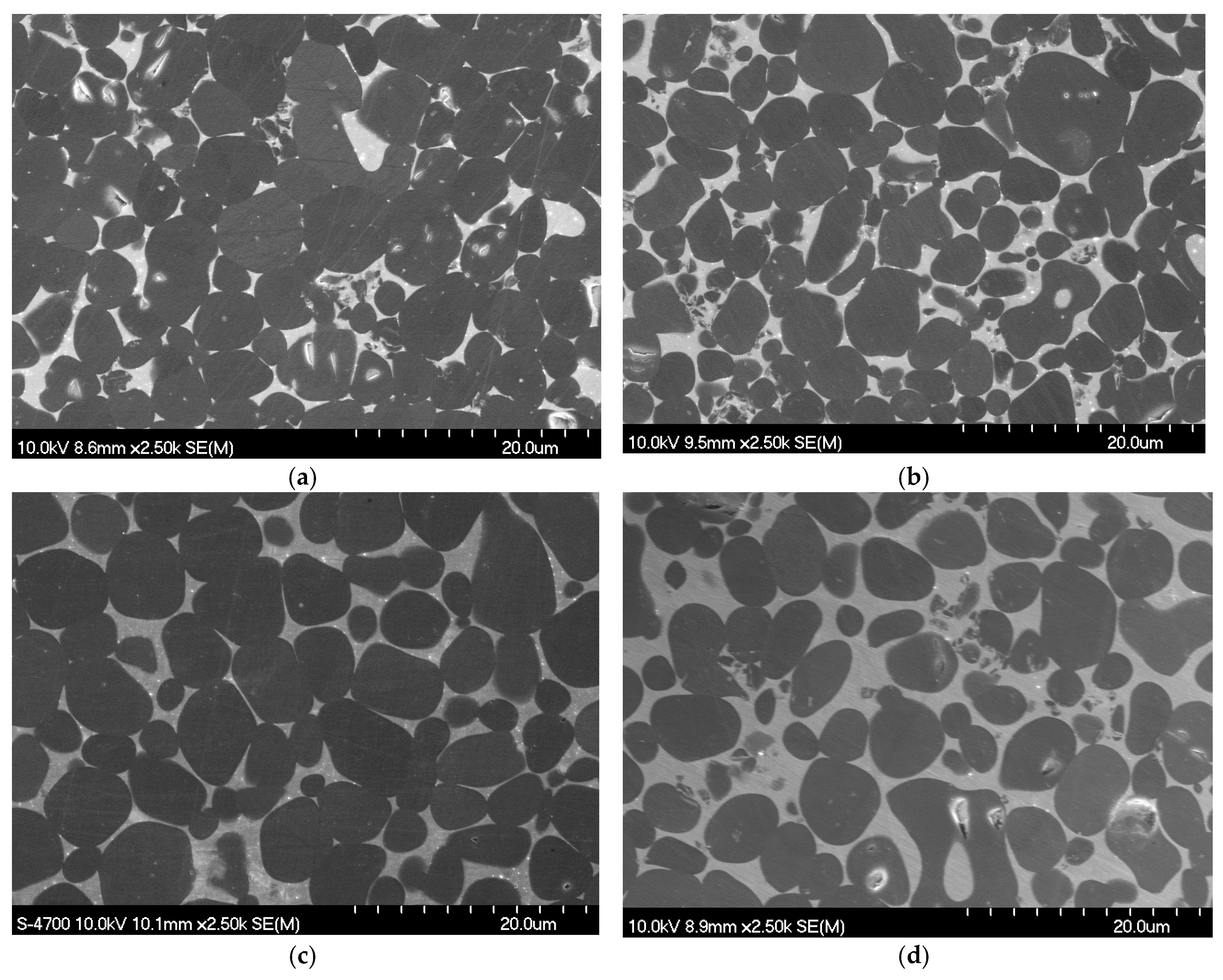
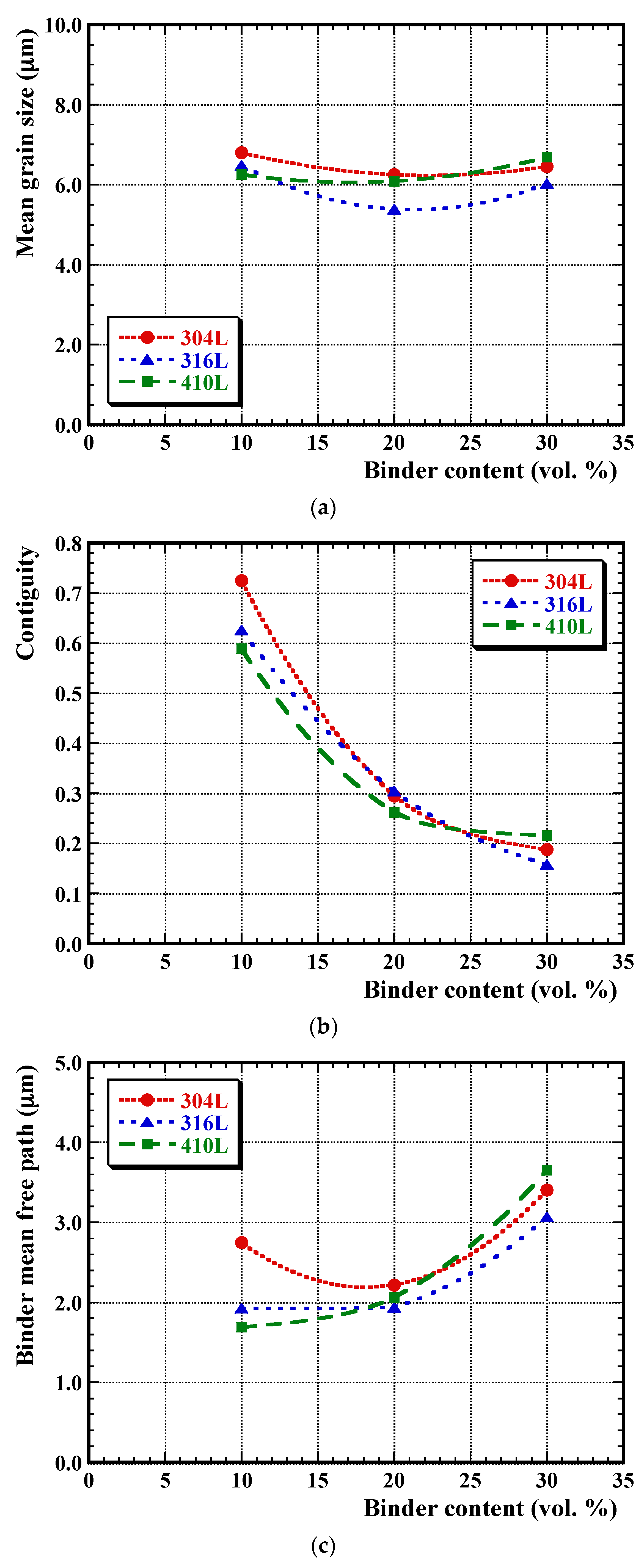
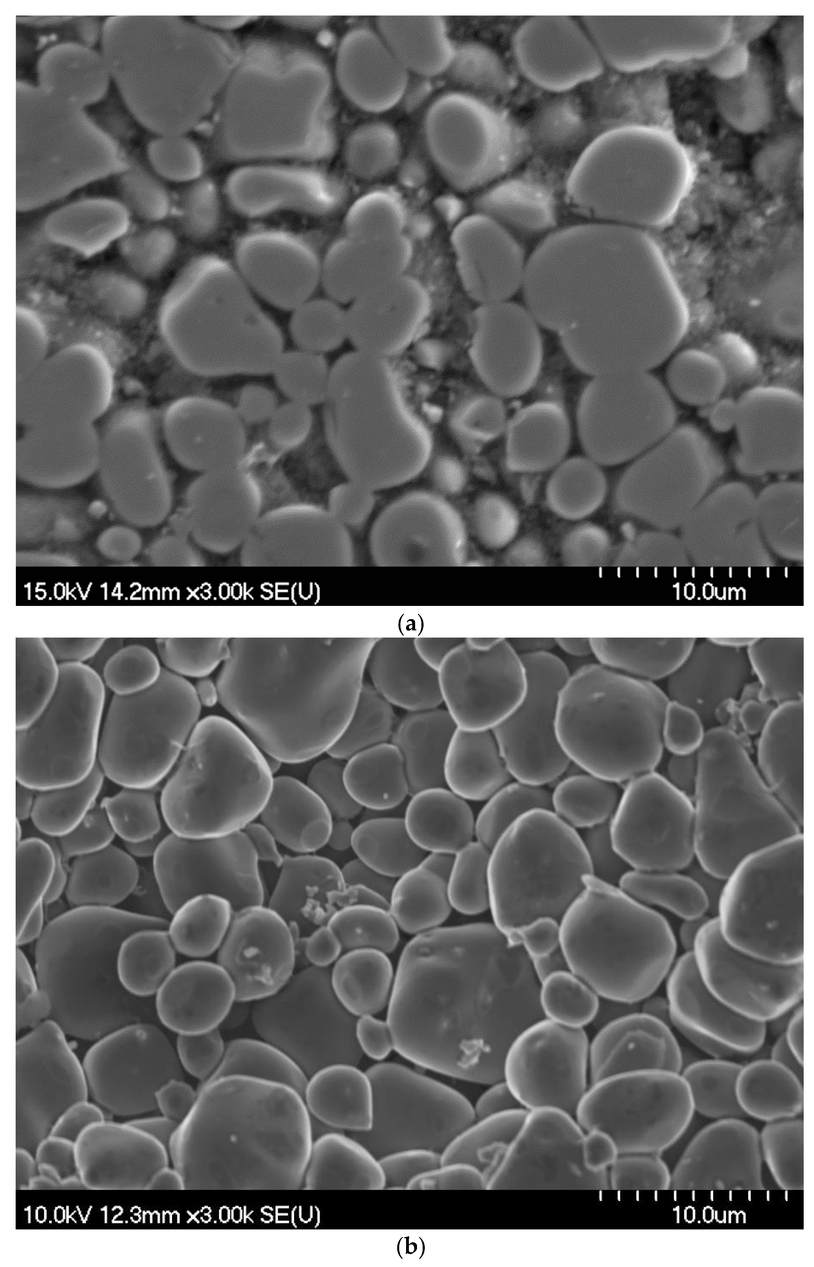
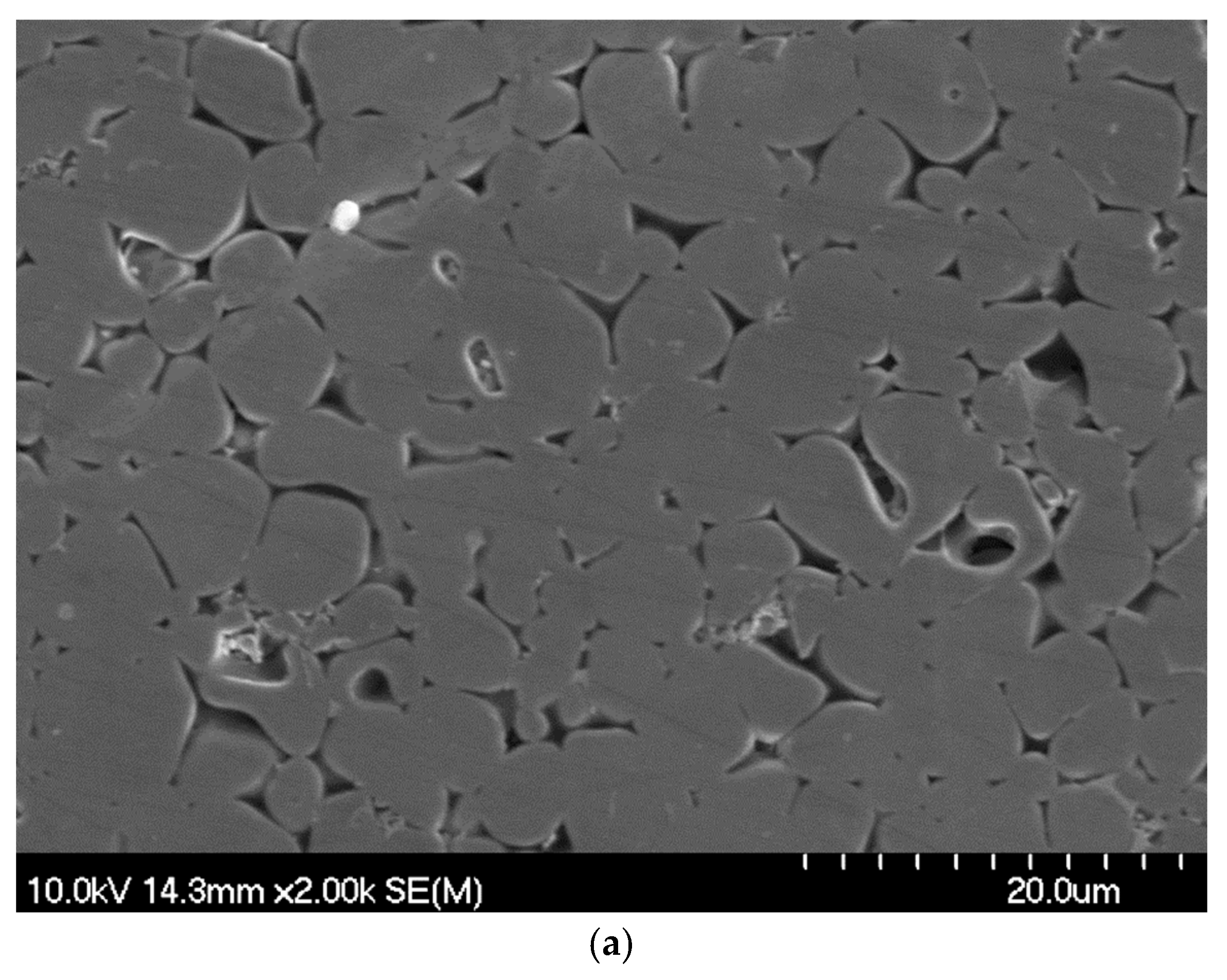
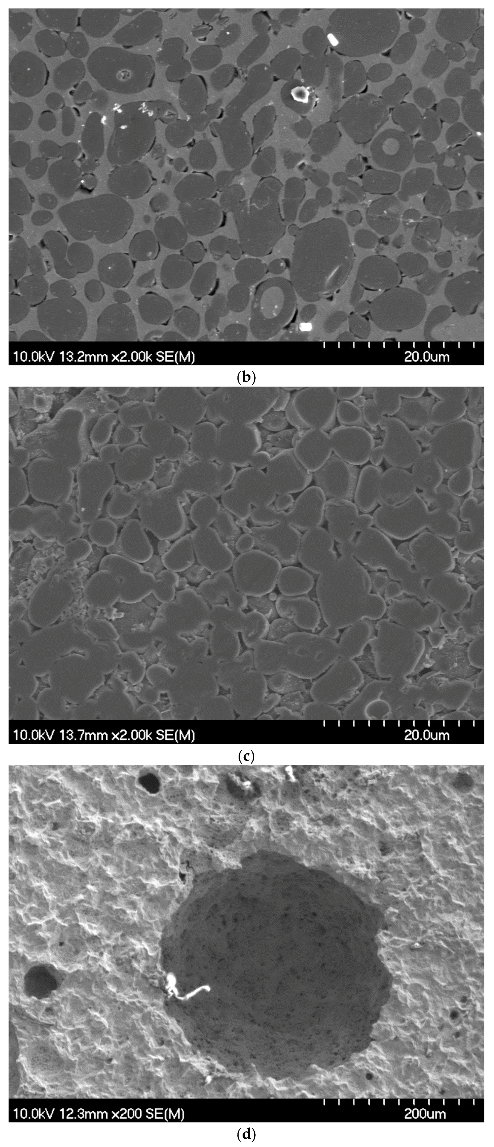
3.1. Microstructural Development

All of the samples were densified in excess of 99% of theoretical (based on a simple rule-of-mixtures for the starting constituent densities). Representative SEM images of the microstructures of the TiC–stainless steel cermets are shown in Figure 1, confirming the high degree of densification that was achieved for each compositional variant. The mean grain size was consistent for each composition at ~6 μm (Figure 2a). The carbide–carbide contiguity is observed to decrease in a steady manner with increasing binder content (Figure 2b), while the binder mean free path increases with the binder content (Figure 2c). These microstructural observations regarding contiguity and binder mean free path are generally consistent with prior studies of TiC-Ni3Al cermets [30]. It is clear from Figure 2 that the microstructural interrelationships are relatively complex. For example, at low binder contents, there is a significant increase in the amount of carbide–carbide contact (as the contiguity rises by a factor of ~3). As a consequence, the TiC phase is far more “continuous” for low steel contents (with more “isolated” steel regions), and becomes more isolated in a continuous steel phase for high steel contents; this is clearly apparent when comparing Figure 1a,d.

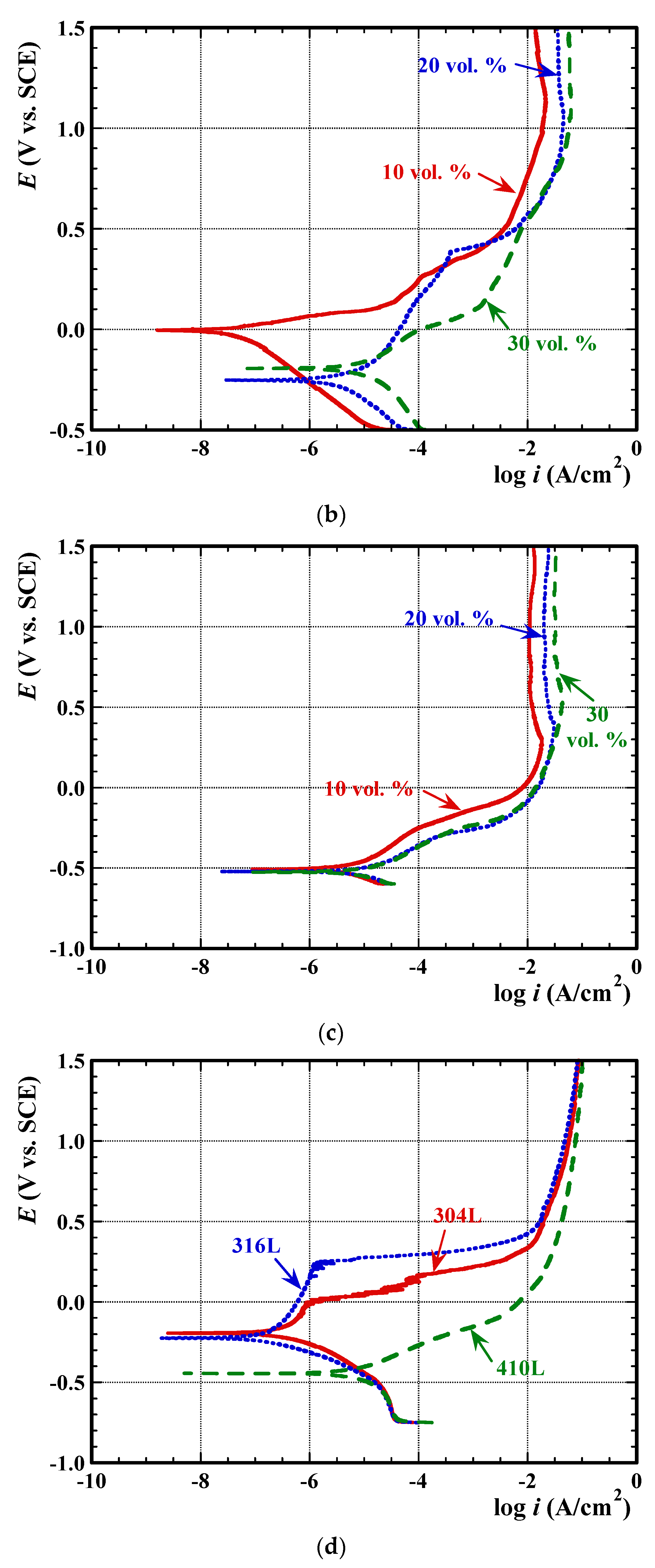
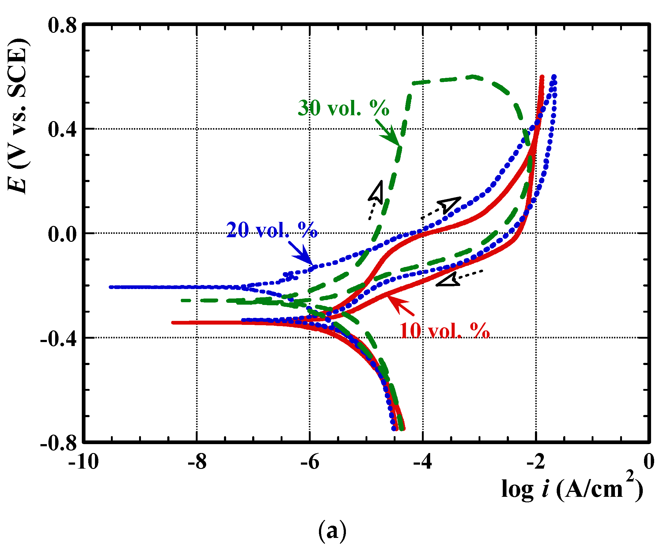
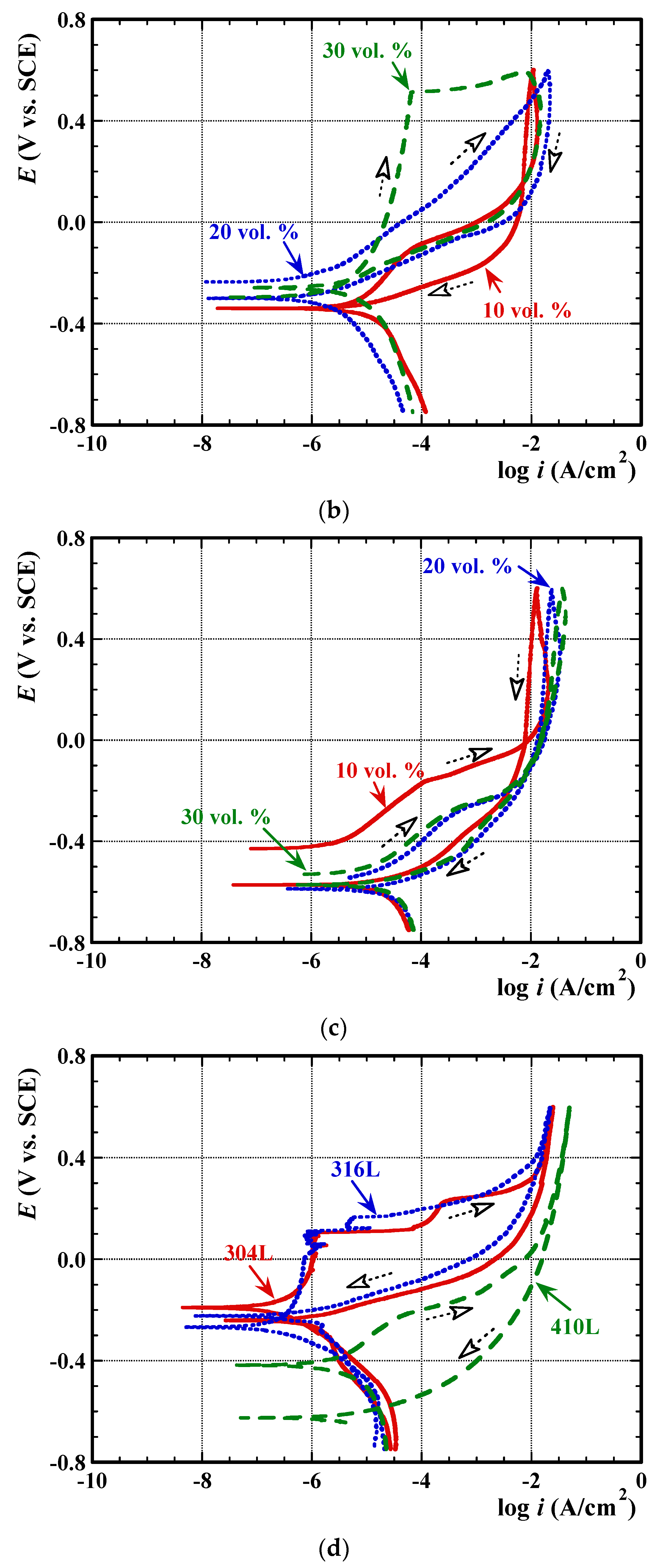
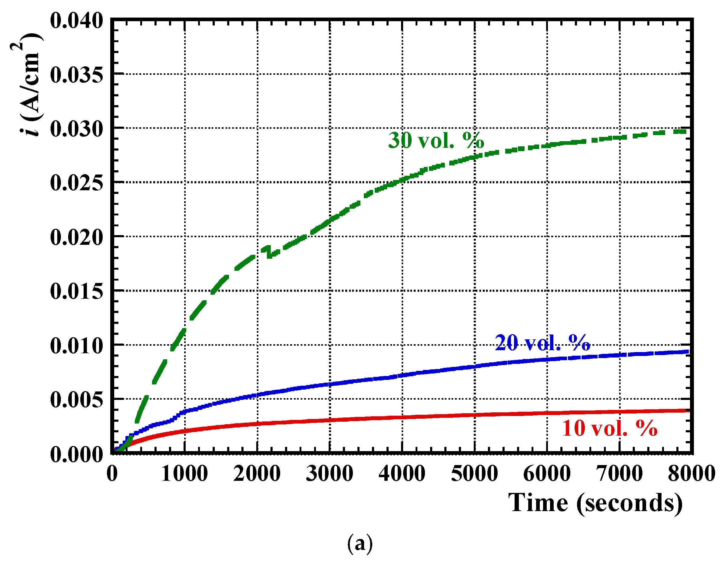
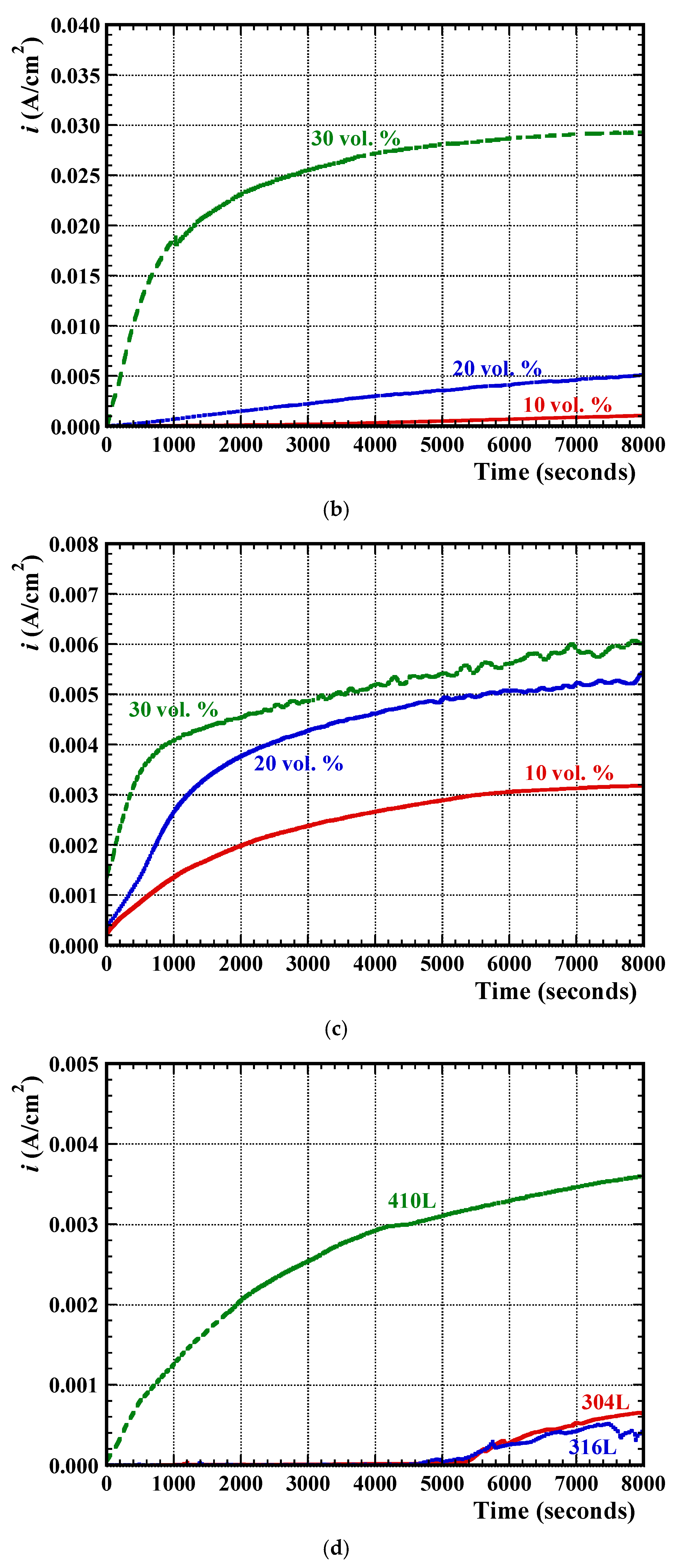
3.2. Electrochemical Measurements

The relative OCP values determined for each of the cermet and single metallic phase compositions are presented in Table 2. The OCP values for the metallic phase steels are less negative (i.e., more noble) than the corresponding cermets, which indicates better surface passivation and protection behaviour and, consequently, corrosion resistance [38]. The OCP values for the cermets generally become more negative with increasing steel binder content, but on occasion show a slight deviation from this trend at the highest binder content. This is particularly apparent for TiC-316 L, where the mean OCP value for samples with 30 vol. % binder is less negative than for 10 vol. % binder samples. The more noble OCP values that were generally observed at the lowest steel binder content for each cermet can be attributed to the formation of a (partially) protective surface layer. This can be anticipated to be an oxide of titanium, and further evidence in support of this is presented in a subsequent section (Post-Corrosion Chemical Analysis). It should be noted that TiC and related ceramics behave in a broadly similar manner to pure Ti, in that they form a TiO2 protective oxide layer [39,40,41].
Typical examples of the potentiodynamic polarisation plots obtained for each of the TiC–stainless steel cermets, as well as the baseline steels, are shown in Figure 3. Table 3 presents the accompanying quantitative data obtained after potentiodynamic polarisation experiments.
The results of the potentiodynamic polarisation have shown that the critical current density, icrit, and “pseudo-passive” current density, ipass, both increase with increasing steel binder content. This response relates to the passivation tendency of the cermets. The low critical anodic current density at the peak of each of the curves indicates that the specimens passivate quickly [42], which indicates that the greater TiC fraction at the lowest binder contents is contributing to the corrosion resistance of the cermets. Similar results have also been reported by Sacks [9], who noted an increase in icrit with an increase in Co content during corrosion studies of WC-Co cermets. Sutthiruangwong and Mori also reported an increase in icrit, icorr, and ipass with decreasing WC content [14], which mirrors the observations presented in Table 4.
From both Figure 3 and Table 4, it can be noted that the current responses in the passive region are relatively high to be viewed as a true passive material (i.e., of the order of 10−2 A/cm2) [12]. Generally, for materials exhibiting “pseudo-passivity” at high electrochemical potentials, after reaching a critical current density, there will be a slight drop in current in the passivation region, as apparent in Figure 3. The passive current density measured for each of the cermets is approximately four orders of magnitude higher than for a true passive material (i.e., 10 µA/cm2). The probable reason for the high current observed in the pseudo-passive region is related to the formation of a weak, cracked, and/or porous oxide, thereby allowing the penetration of the electrolyte to the cermet surface [11]. The presence of such an oxide scale, which still inhibits diffusion to a certain extent, leads to a limitation of the current density [12].
To determine the corrosion current density, icorr, and potential, Ecorr, Tafel extrapolations were performed following the potentiodynamic polarisation tests; data obtained from these analyses is presented in Table 4. It is apparent that both icorr and Ecorr for the cermets increase with increasing steel binder content. In comparison, the values of icorr for each of the single phase metallic steels is lower than for the cermets, again indicating better corrosion resistance of the metallic phase by itself.
Based on the results of Tafel extrapolation, it was observed that the corrosion rate increases with binder content for all of the cermets (Figure 4a). It is believed that this response arises from effectively increasing the TiC surface area, at lower binder volume fractions, with the TiC likely being semi-protected by an oxide surface layer [41,43]. These corrosion rate trends determined from the Tafel experiments are in general agreement with the observations of Sacks [9], who studied the corrosion behaviour of WC-Co composites in tannic acid-based electrolytes, and reported an increase in the corrosion rate with increasing Co binder content. It was demonstrated that there was a preferential dissolution of the Co binder, while the WC grains retained their sharp facets, and are effectively not attacked during the corrosion tests [9].
Using a broadly similar Tafel approach, Toma et al. determined aqueous corrosion rates for WC-Co and WC-CoCr, and demonstrated the former to be ~0.76 mm/year, which is lowered to ~0.32 mm/year through the addition of Cr [44]. The best cermet coating systems for corrosion resistance are presently those based on Cr3C2, with a NiCr binder that has been demonstrated to exhibit aqueous corrosion rates as low as 0.008 mm/year [45]. Some caution should be taken when evaluating these different materials, particularly in comparing bulk cermets and coatings, where coating porosity may play a role in degrading the corrosion properties. However, the present materials exhibit generally similar performance, in comparison to the Cr3C2-based cermets, when assessing electrochemically derived (i.e., Tafel) corrosion rates. When contemplating the electrochemical response of the present materials, it is important to consider which components might be playing an active role in corrosion, and which may be inert.
Following the outlined Tafel extrapolation approach provides an apparently clear dependency of corrosion rate as a function of binder content. However, Hochstrasser-Kurz et al. noted that the metallic component in their system, namely WC-Co, was selectively removed, and therefore the effective corroding area should be based on the metallic component only [22]. Taking the same approach in the current work, Figure 4b presents revised corrosion rate data, where only the metallic component is participating; here, it is assumed that the area fraction of the metallic component is equivalent to the volume fraction. In this instance, the corrosion rates are based on revised values for icorr, due to the reduced cross-sectional area undergoing corrosion. These modified area values for icorr, termed icorrMA, were presented previously in Table 4. This “normalisation” approach largely eliminates any obvious dependency of corrosion rate upon the steel binder content, although trends between steel binder compositions are still apparent.
When examining the corrosion mechanism for the present cermets, it can be initially postulated that the electrochemical response is related (at least in part) to a potential galvanic effect between the TiC and steel binder. Given a nominally constant grain size (Figure 2a), as the binder content is reduced, the carbide–carbide contacts increase (Figure 2b). In terms of the microstructure, there is a transition from a nominally continuous TiC framework, with isolated islands of steel, to a continuous steel structure, with isolated TiC grains (Figure 1). This clearly results in a complex relationship between the steel binder fraction and the carbide/metal interfacial area. Looking specifically at the system components, the corrosion potential of a single-phase TiC ceramic, prepared from the same TiC powder as the present work (with some W contamination), in an equivalent 3.5 wt. % NaCl electrolyte was determined to be −0.176 V (vs. SCE) [46]. Interestingly, that work showed the effects of powder composition, as a high-purity TiC sample exhibited a corrosion potential of +0.005 V (vs. SCE). It can consequently be anticipated that the difference in corrosion potentials between the TiC ceramic phase and the steel binder, in a conducting electrolyte, may potentially lead to galvanic activity at the interfaces between these two dissimilar materials, especially for the 410 L grade.
It can be seen from Table 5 that, of the baseline metals, 316 L stainless steel has the best corrosion resistance, but when incorporated with TiC into a cermet structure, the TiC-304 L cermets have better corrosion resistance than their TiC-316 L and TiC-410 L counterparts (Figure 4). This is likely related to a reduced difference in the electrochemical potentials and galvanic activity between the TiC and the steel binder. Generally, when two dissimilar materials are incorporated in a conducting electrolyte, and one is more noble (cathodic) while the other is more active (anodic), the difference in potential between the cathode and anode site will indicate the expected degree of galvanic corrosion. Consequently, the smaller the difference in potential, the lower the expected extent of galvanic corrosion [40]. However, changes in electrolyte composition and temperature could also alter the potential positioning in the galvanic series [40]. As noted in the previous paragraph, the corrosion potential of the present TiC (as a single-phase material) in a similar electrolyte to the current study was determined to be −0.176 V [46], while those of 304 L, 316 L, and 410 L steels (shown in Table 4) are approximately −0.204, −0.221, and −0.400 V (versus SCE), respectively. Comparing the difference in the OCP between TiC (cathodic) and the metallic phase (anodic), based on this principle, TiC and 304 L offer the least likely candidates for the formation of a galvanic couple due to exhibiting the lowest potential difference between the two phases. This is further investigated by the performance of the cyclic polarisation analysis. The results of cyclic analysis, such as characteristics of the hysteresis loops and the pitting (Epit) and repassivation/protection potentials (Eprot), was used to confirm the susceptibility of each composition toward localised corrosion, similar to those initiated in ceramic/metallic interface within the composition.
The cyclic polarisation responses of the cermets and the baseline steels are presented in Figure 5. The pitting and repassivation (or protection) potentials (Epit and Eprot, respectively) are used to study the susceptibility of the materials to localised corrosion. The relative degree of “self-healing” ability of the surface film is then given by [47,48]:
Δ E = E _ p i t E _ p r o t
The accompanying electrochemical results of the cyclic polarisation experiments are shown in Table 5. Where the value of Eprot is lower than Ecorr, no protection will be observed, and this is noted as such in the table. It is typical that an increase in Epit improves the resistance of the materials to pitting corrosion, while a decrease of ∆E indicates a greater ability towards the self-healing of the passively formed surface film [47]. By increasing the steel binder content, the pitting resistance of the cermets is improved (i.e., Epit increases with binder content).
For the TiC cermets prepared with 304 L and 316 L, positive values of ∆E in addition to anti-clockwise (−) and relatively small hysteresis loops, were observed for the cermets containing only 10 vol. % of the metallic binder phase. This behaviour is likely related to the protection rendered by the formation of a surface oxide at the comparatively higher TiC content (effectively 90% of the surface area). Further increases in amounts of 304 L or 316 L binder resulted in the formation of large, clockwise (+) hysteresis loops, which can be interpreted as an increased susceptibility of these compositions towards localised corrosion.
On the other hand, cyclic polarisation tests on the cermet compositions prepared with 410 L steel showed a very different behaviour. The cermets with a 410-L steel binder consistently exhibited anti-clockwise (−) hysteresis loops, with the smallest loop corresponding to the composition with 30 vol. % of the metallic binder phase. It was also observed that the calculated ∆E increased with an increasing binder content.
To further confirm the observations from cyclic polarisation, and to substantiate the possibility of localised corrosion, potentiostatic polarisation tests were conducted at applied voltages slightly above Epit (Figure 5); the specific polarisation voltages used for each sample are provided in Table 6. All of the present materials showed an increase in current with time during the potentiostatic scans above Epit, indicating the probability of localised corrosion. These observations confirm the results of the cyclic polarisation tests shown previously. It can also be seen from Figure 6 that the cermets with 10 vol. % 304 L and 316 L steel showed an increase in current with time. This again infers the superior capacity of the lower binder content cermets towards the better oxidation resistance of the passive film, when compared with the other cermets studied. The large oscillations observed in the potentiostatic curves for the pure 316 L and 304 L stainless steels presents evidence of localised corrosion, and an aggressive attack of the passive film by Cl ions.

3.3. Post-Corrosion Sample Characterisation

Typical SEM images of the cermets after potentiodynamic polarisation testing are shown in Figure 7; in these examples, the cermets have been subjected to an accelerated corrosion through a voltage sweep to +1.5 V (versus SCE). Preferential dissolution of the binder is apparent, while the TiC grains remain largely unaffected following the tests. Even when the steel binder is removed, the TiC particles support each other to a large extent and form a continuous, rigid skeleton. However, some surface TiC grain removal does occur; the presence of remnant surface grains can be easily observed in the form of a retained, uniform flattened face (i.e., previously polished) on each individual grain (e.g., Figure 7a).
It can be clearly seen that at the highest binder contents, essentially all of the interconnecting metal binder content is removed from the near surface region, leaving clean and smooth TiC grains (Figure 7b). In this instance, the surface TiC grains are also removed, as TiC particles are clearly rounded at the new surface (i.e., the previously polished grains are removed).
The typical effects of cyclic polarisation on the cermets and the accompanying baseline steels are shown in Figure 8. It is apparent that there is heavy pitting on the baseline steel surfaces (Figure 8d), which is in agreement with the experimental results of the cyclic polarisation tests, as shown in Figure 5. In that instance, the values of Eprot for the steels (i.e., the protection potential) are more active than Epit, indicating the tendency for localised corrosion. The presence of pits also relates to the oscillatory response observed for the steels during the cyclic and potentiostatic polarisation experiments (Figure 5 and Figure 6, respectively), which indicates evidence of Cl ion attack [39]. However, for the TiC–stainless steel cermets, there is only a selective attack occurring locally at the interface between the TiC and the steel binder, resulting in the removal of the binder itself. In this situation, the TiC ceramic particles are not affected in any obvious way. The initial stages of this corrosive process are clearly shown in Figure 8b, with nominally lenticular-shaped voids appearing at the interface between the TiC and the steel phase (in this case, 316 L). Here, the bulk of the steel is still retained, but the initial stages of material loss are clearly associated with the interfacial region, indicating the dominance of a galvanic mechanism (rather than general corrosion), as outlined earlier. Close inspection of the TiC grains in the image shows that they invariably have consistent surface curvature, inferring that material loss arises from the steel binder (as predicted by the galvanic corrosion argument), which is the anodic portion of the galvanic couple. It is interesting to note that there is, broadly speaking, an association of the attacked regions with areas where there are closely neighbouring TiC grains. This indicates that residual stress and/or localised dislocation density in the steel may also play a role in corrosion in the interfacial region.
The lack of substantial evidence for pitting on the cermets can be postulated to be due to the beneficial protective effect offered by the formation of a (partially protective) surface oxide which, based on prior studies [41,42], is likely to be a titanium oxide (i.e., TiO2) for the current cermets. From the present work, it can be clearly seen that there is a selective interfacial attack on the cermets, resulting in steel binder loss, while the TiC grains are unaffected. As noted previously, it is expected that the anodic area is the metallic side of the interface between the steel binder and hard TiC phase (where metallic dissolution takes place), whereas the adjacent ceramic side of interface is the cathodic region (where oxygen reduction takes place), although in the case of both 304 L and 316 L, the corrosion potential differences with the present TiC are small. Within the interface zone (anodic region), metal dissolution occurs, and increases the migration of chloride ions into the interface. The formation of metal cations may be anticipated to lower the pH (acidifying the solution) near the interface, due to the hydrolysis of metal cations, leading to the more intensive corrosion in this region. This theory could also potentially explain the localised corrosion at the interface of the cermets, acting in conjunction with galvanic attack. However, one further factor needs to be considered, in that there is some evidence of localised compositional change in these cermets during fabrication, as noted in an earlier study [49]. It was shown, specifically for the TiC-316 L system, that the binder composition is modified, as Mo is removed to a large extent, and is incorporated into the outer rim of a complex core–rim structure that is formed on the TiC grains. This outer rim contains Mo and also W, which was present as an impurity in the starting TiC powder.

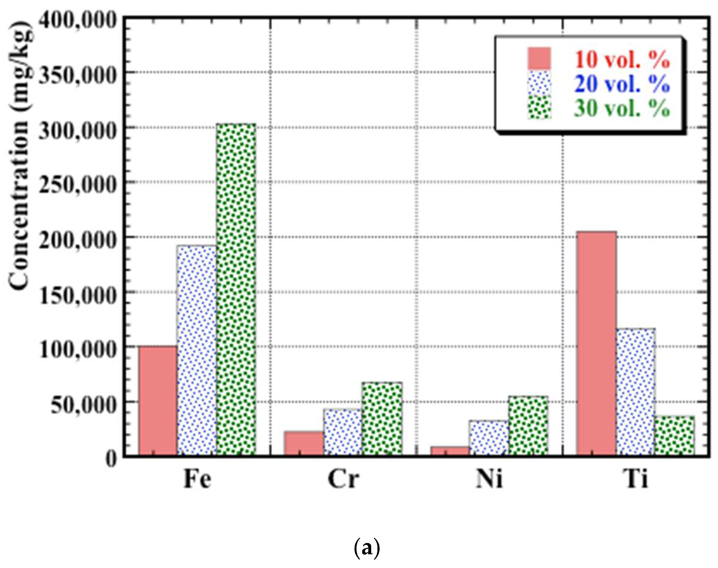
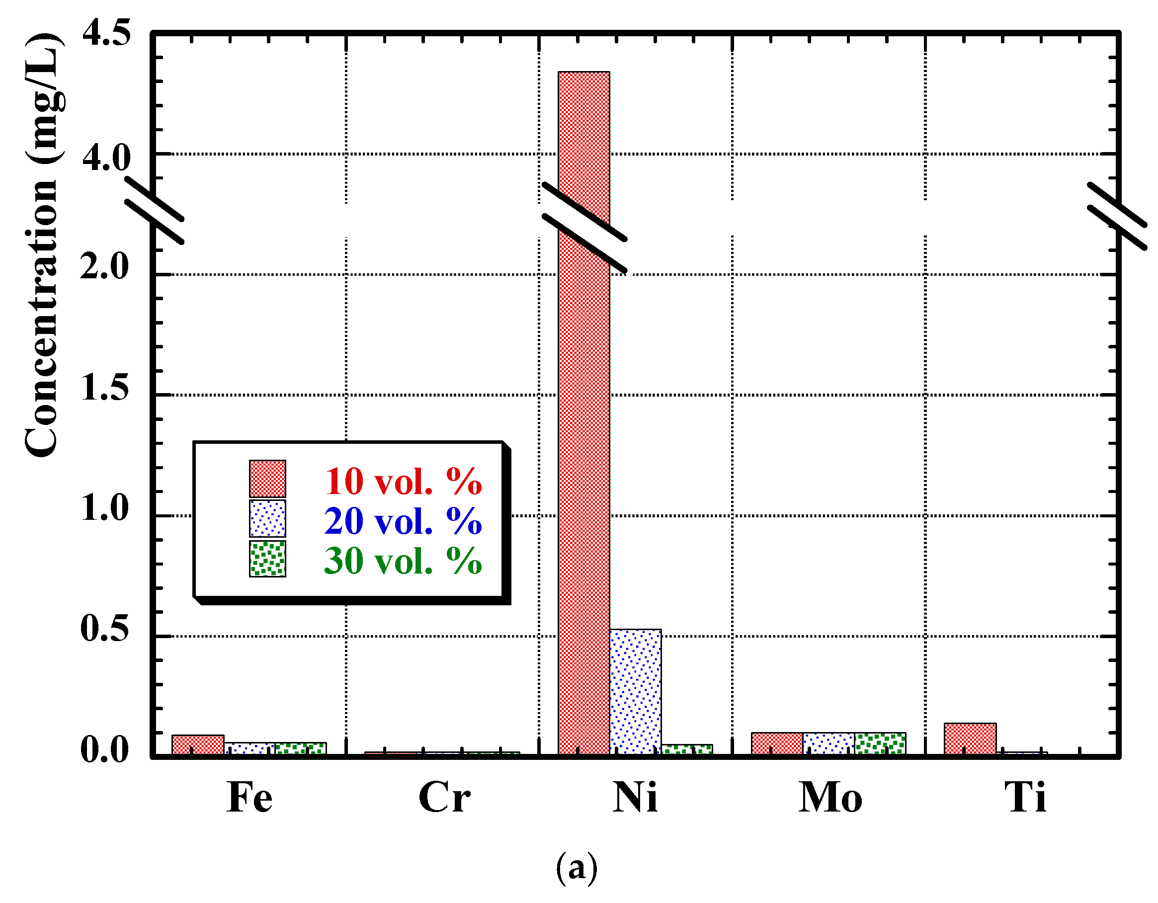
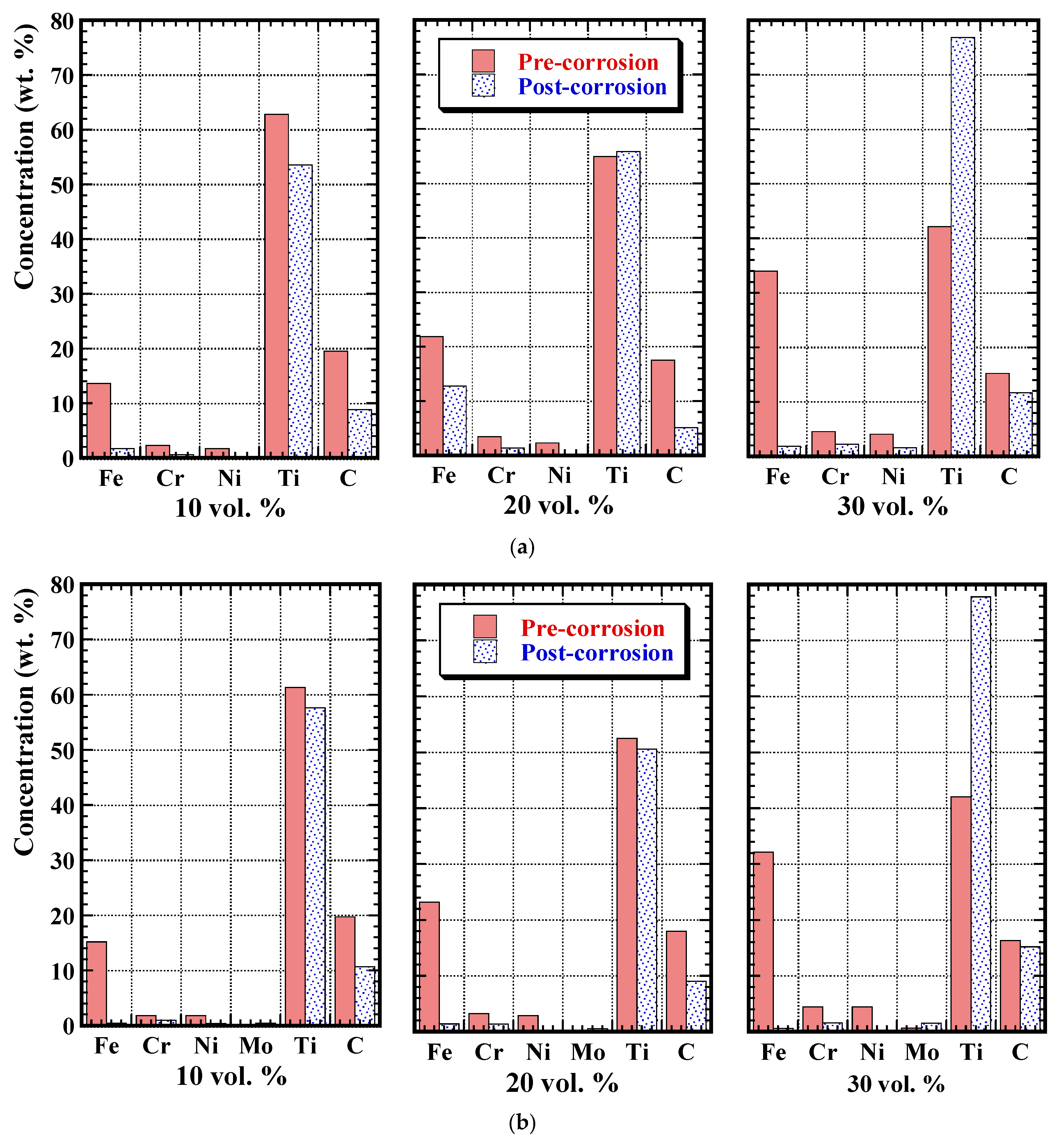
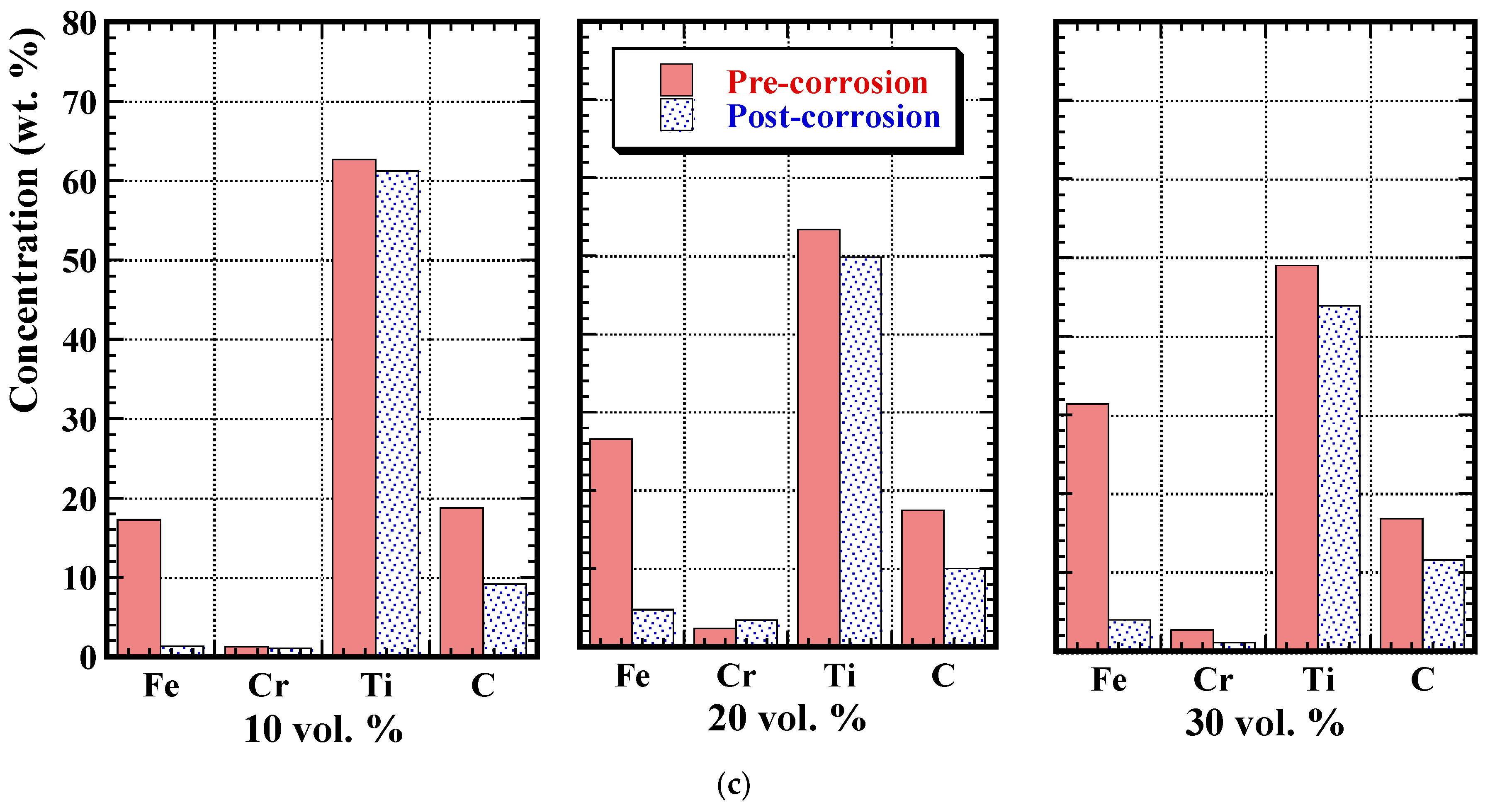
3.4. Post-Corrosion Chemical Analysis

Following the corrosion experiments, the remaining solution from the electrochemical cell was analysed using ICP-OES, to determine both the solid (in terms of fine particulate matter) and ionic (dissolved) material present in the solution. Assessment of the primary constituent species is presented in Figure 9 and Figure 10 for the solid and ionic material, respectively. In terms of the solid constituents, with increasing binder content, it is apparent that there are concurrently increasing quantities of the steel components (e.g., Fe, Ni, and Cr) liberated during corrosion testing (Figure 9). Conversely, there are relatively decreasing amounts of Ti present. The increase in the assorted steel species indicates that there is a preferential attack of the binder, the extent of which increases in a nominally linear manner with the overall binder content of the cermets. This observation is in accordance with the SEM observations.
By comparing the dissolution of Fe for the three cermet systems, it is apparent that the TiC-410 L cermets have the highest binder dissolution rate, followed by TiC-316 L and lastly, TiC-304 L. This observation also confirms the superior corrosion resistance of TiC-304 L cermets over the other developed compositions, as outlined earlier, contrary to the behaviour for the steels in isolation. Figure 10a shows the ionic content measured in the filtered solutions (i.e., after removal of all of the particulate material), following the corrosion experiments for each cermet. There is invariably a greater amount of Ni and Mo ions in the filtered solutions after testing the TiC-316 L compositions (i.e., Figure 10b) when compared with other cermets. The loss of Ni and Mo ions, which are important components that improve the corrosion resistance of the steel, may indicate why the TiC-316 L cermets showed marginally inferior corrosion resistance compared with TiC-304 L, where the loss of Ni ions is minimal. The absence of Fe ions from the solution may indicate the precipitation of Fe in some form, which would then lead to a higher Fe content in the recovered solids component, relative to Ni. As the pH of the NaCl solution is between 5.3–5.8, which is relatively close to the highly acidic and corrosive pH range [0–4], the possibility of Fe precipitation can be justified [50].
In addition to analyses of the various residual corrosion solutions after electrochemical testing, the influence of the tests on the cermet composition was also analysed. Figure 11 presents the surface EDS analyses, both before and after corrosion testing, for each of the cermet systems; it should be noted that the balance for each of the samples is comprised of O (in wt. %). It is apparent that there is heavy dissolution (and hence removal) of the metal binder components during corrosion, for each of the cermet systems, while the TiC is essentially unaffected. It is also notable that the O content increases significantly, from essentially nothing in the as-fabricated cermets, confirming the formation of a surface oxide during corrosion [34,35,36]. These analyses confirm that there is selective dissolution of the binder, supporting the ICP-OES data presented in Figure 9 and Figure 10, and the prior SEM observations (Figure 7 and Figure 8). In the most extreme corrosion cases, it can be expected that there will also be a slight loss of Ti (and C), due to the removal of individual TiC grains when the metal binder is degraded (there is no longer a sufficient steel binder to keep the surface grains in place); this will not be observed by EDS analysis, as Ti and C will still be the predominant components, but can be observed through SEM imaging, as the surface morphology will change from polished (i.e., smooth) to rough (i.e., revealing complete, individual TiC grains), and also through the ICP-OES data (Figure 9 and Figure 10).

4. Conclusions

The corrosion behaviour of TiC–stainless steel cermets has been assessed in a simulated seawater environment (with 3.5 wt. % NaCl), using a combination of electrochemical measurements, together with microstructural and compositional analyses. The cermets have been prepared with the steel binder compositions 304 L, 316 L, and 410 L (varied from 10 vol. % to 30 vol. %). Efforts were made during cermet processing to ensure an essentially identical grain size in order to eliminate any issues arising from changing the ceramic–metal interfacial area (due to grain size). Based on this study, the following conclusions can be drawn:
(1) The corrosion resistance of the baseline 316 L, 304 L, and 410 L steels is generally slightly better than the TiC–stainless steel cermets with higher binder contents, but comparable to the 3xx series cermets with the lowest binder content (i.e., 10 vol. % steel), which offer significantly superior wear resistance (by roughly three orders of magnitude).
(2) For the “pure” baseline steels, the 316 L stainless steel has the best corrosion resistance, followed by 304 L, and finally 410 L. Conversely, for the cermets, the TiC-304 L system has the best corrosion resistance, followed by TiC-316 L, and lastly TiC-410 L.
(3) For the cermets, generally Ecorr becomes more negative with increasing steel binder content, while icorr is increased with increasing binder content, indicating a reduced corrosion resistance (although the effects are small in both cases). Based on a constant corrosion area (i.e., 1 cm2 exposed area), the corrosion rate of the cermets is seen to increase with steel binder content, which is related to the selective dissolution of the metallic phase (relative to the ceramic phase); this corrosion rate effect is largely negated by normalising to just the exposed “active” metal area.
(4) Microstructural studies revealed the preferential dissolution of the steel binder, while the TiC grains remained largely unaffected. This is potentially a result of galvanic action, with the more anodic response of the metal component resulting in its removal (particularly for the 410 L binder materials). Chemical analyses, using both ICP-OES and EDS, confirmed this increase in dissolution of the steel binder at higher binder contents. At low binder contents, EDS analysis also shows that there is an increased amount of semi-protective oxide on the sample surface (which was anticipated to be TiO2).
(5) Based on both the electrochemical measurements and the microstructural analyses, it can be concluded that the cermets with the lowest binder content (i.e., 10 vol. %) have the potential to offer a combination of good corrosion resistance and excellent wear resistance, as dissolution of the binder is significantly reduced during aqueous corrosion, while the high TiC content would provide enhanced wear resistance.

Author Contributions

K.P., G.K. and Z.F. conceived and designed the experiments. All experimental work was completed by C.O. and Z.R. (née Memarrashidi). C.O., Z.R. and K.P. analysed the data and wrote the paper, with G.K. and Z.F. providing input upon editing the initial draft.

Acknowledgements

This study was financially supported by Petroleum Research Atlantic Canada (PRAC), under grant #C9-10, and the Natural Sciences and Engineering Research Council of Canada (NSERC), under grant #CRDPJ 381565-09. The Canada Foundation for Innovation, the Atlantic Innovation Fund, and other partners who helped fund the Facilities for Materials Characterisation, managed by the Dalhousie University Institute for Materials Research, are also gratefully acknowledged. The authors would also like to thank Dean Grijm and Patricia Scallion for technical assistance.

Conflicts of Interest

The authors declare no conflict of interest.

References

  1. Liu, H.Y.; Huang, J.H.; Yin, C.F.; Zhang, J.G.; Lin, G.B. Microstructure and properties of TiC-Fe cermets coatings by reactive flame spraying using asphalt as carbonaceous precursor. Ceram. Int. 2007, 33, 827–835. [Google Scholar] [CrossRef]
  2. Ettmayer, P.; Kolaska, H.; Dreyer, K. Effect of the sintering atmosphere on the properties of cermets. Powder Metall. Int. 1991, 23, 224–230. [Google Scholar]
  3. Pirso, J.; Viljus, M.; Letunovits, S. Sliding wear of TiC-NiMo cermets. Tribol. Int. 2004, 37, 817–824. [Google Scholar] [CrossRef]
  4. Pirso, J.; Viljus, M.; Juhani, K.; Letunovits, S. Two-body dry abrasive wear of cermets. Wear 2009, 266, 21–29. [Google Scholar] [CrossRef]
  5. Onuoha, C.C.; Farhat, Z.N.; Kipouros, G.J.; Plucknett, K.P. The effects of TiC grain size on the sliding wear behaviour of TiC-316L stainless steel cermets. Wear 2013, 303, 321–333. [Google Scholar] [CrossRef]
  6. Manoj Kumar, B.V.; Balasubramanian, R.; Basu, B.J. Electrochemical behaviour of TiCN-Ni-based cermets. J. Am. Ceram. Soc. 2007, 90, 205–210. [Google Scholar] [CrossRef]
  7. Ghandehari, M.H. Anodic behaviour of cemented WC-6-percent Co alloy in phosphoric acid solutions. J. Electrochem. Soc. 1980, 127, 2144–2147. [Google Scholar] [CrossRef]
  8. Sutthiruangwong, S.; Mori, G.; Kosters, R. Passivity and pseudopassivity of cemented carbides. Int. J. Refract. Met. Hard Mater. 2005, 23, 129–136. [Google Scholar] [CrossRef]
  9. Sacks, N. The Wear and Corrosive-Wear Response of Tungsten Carbide-Cobalt Hardmetals under Woodcutting and Three Body Abrasion Conditions. Ph.D. Thesis, University of Erlangen-Nurnberg, Bavaria, Germany, 2002. [Google Scholar]
  10. Tomlinson, W.J.; Linzell, C.R. Anodic polarization and corrosion of cemented carbides with cobalt and nickel binders. J. Mater. Sci. 1988, 23, 914–918. [Google Scholar] [CrossRef]
  11. Human, A.M.; Northrop, I.T.; Luyckx, S.B.; James, N.M. A comparison between cemented carbides containing cobalt- and nickel-based binders. J. Hard Mater. 1991, 2, 245–256. [Google Scholar]
  12. Human, A.M.; Exner, H.E. Electrochemical behavior of tungsten carbide hard metals. Mater. Sci. Eng. A 1996, 209, 180–191. [Google Scholar] [CrossRef]
  13. Human, A.M.; Exner, H.E. The relationship between electrochemical behavior and in-service corrosion of WC based cemented carbides. Int. J. Refract. Met. Hard Mater. 1997, 15, 65–71. [Google Scholar] [CrossRef]
  14. Sutthiruangwong, S.; Mori, G. Corrosion properties of Co-based cemented carbides in acidic solutions. Int. J. Refract. Met. Hard Mater. 2003, 21, 135–145. [Google Scholar] [CrossRef]
  15. Banerjee, D.; Lal, G.K.; Upadhyaya, G.S. Effect of binder-phase modification and Cr3C2 addition on properties of WC-10Co cemented carbide. J. Mater. Eng. Perform. 1995, 4, 563–572. [Google Scholar] [CrossRef]
  16. Tomlinson, W.J.; Ayerst, N.J. Anodic polarization and corrosion of WC-Co hard metals containing small amounts of Cr3C2 and/or VC. J. Mater. Sci. 1989, 24, 2348–2354. [Google Scholar] [CrossRef]
  17. Human, A.M.; Roebuck, B.; Exner, H.E. Electrochemical polarisation and corrosion behaviour of cobalt and Co(W,C) alloys in 1N sulphuric acid. Mater. Sci. Eng. A 1998, 241, 202–210. [Google Scholar] [CrossRef]
  18. Monticelli, C.; Frignani, A.; Zucchi, F. Investigation on the corrosion process of carbon steel coated by HVOF WC/Co cermets in neutral solution. Corros. Sci. 2004, 46, 1225–1237. [Google Scholar] [CrossRef]
  19. Trueman, A.; Schweinsberg, D.P.; Hope, G.A. A study of the effect of cobalt additions on the corrosion of tungsten carbide/carbon steel metal matrix composites. Corros. Sci. 1999, 41, 1377–1389. [Google Scholar] [CrossRef]
  20. Wentzel, E.J.; Allen, C. The erosion-corrosion resistance of tungsten-carbide hard metals. Int. J. Refract. Met. Hard Mater. 1997, 15, 81–87. [Google Scholar] [CrossRef]
  21. Wood, R.J.K. Tribo-corrosion of coatings: A review. J. Phys. D Appl. Phys. 2007, 40, 5502–5521. [Google Scholar] [CrossRef]
  22. Hochstrasser-Kurz, S.; Mueller, Y.; Latkoczy, C.; Virtanen, S.; Schmutz, P. Analytical characterization of the corrosion mechanisms of WC-Co by electrochemical methods and inductively coupled plasma mass spectroscopy. Corros. Sci. 2007, 49, 2002–2020. [Google Scholar] [CrossRef]
  23. Cho, J.E.; Hwang, S.Y.; Kim, K.Y. Corrosion behaviour of thermal sprayed WC cermets coatings having various metallic binders in strong acidic environments. Surf. Coat. Technol. 2006, 200, 2653–2662. [Google Scholar] [CrossRef]
  24. Perry, J.M.; Neville, A.; Hodgkiss, T. A comparison of the corrosion behavior of WC-Co-Cr and WC-Co HVOF thermally sprayed coatings by in situ atomic force microscopy (AFM). J. Therm. Spray Technol. 2002, 11, 536–541. [Google Scholar] [CrossRef]
  25. Patel, M.; Saurabh, K.; Bhanu Prasad, V.V.; Subrahmanyam, J. High temperature C/C–SiC composite by liquid silicon infiltration: A literature review. Bull. Mater. Sci. 2012, 35, 63–73. [Google Scholar] [CrossRef]
  26. Levy, A.; Miriyev, A.; Elliott, A.; Babu, S.S.; Frage, N. Additive manufacturing of complex-shaped graded TiC/steel composites. Mater. Des. 2017, 118, 198–203. [Google Scholar] [CrossRef]
  27. Collier, R.B.; Plucknett, K.P. A comparison of anionic and cationic polyelectrolytes for the aqueous colloidal processing of titanium carbide ceramics. Int. J. Refract. Met. Hard Mater. 2011, 29, 298–305. [Google Scholar] [CrossRef]
  28. Boyer, H.E.; Gall, T.L. Metals Handbook: Desk Edition, 2nd ed.; Davis, J.R., Ed.; ASM International: Geauga County, OH, USA, 1998. [Google Scholar]
  29. Jin, C.; Onuoha, C.C.; Farhat, Z.N.; Kipouros, G.J.; Plucknett, K.P. Reciprocating wear behaviour of TiC-stainless steel cermets. Tribol. Int. 2016, 105, 250–263. [Google Scholar] [CrossRef]
  30. Plucknett, K.P.; Becher, P.F. Processing and microstructure development of titanium carbide-nickel aluminide composites prepared by melt-infiltration/sintering (MIS). J. Am. Ceram. Soc. 2001, 84, 55–61. [Google Scholar] [CrossRef]
  31. Mendelson, M.I. Average grain size in polycrystalline ceramics. J. Am. Ceram. Soc. 1969, 52, 443–446. [Google Scholar] [CrossRef]
  32. Gurland, J. The measurement of grain contiguity in 2-phase alloys. Trans. Metall. Soc. AIME 1958, 212, 452–455. [Google Scholar]
  33. Marquardt, D. An algorithm for least-squares estimation of nonlinear parameters. SIAM J. Appl. Math. 1963, 11, 431–441. [Google Scholar] [CrossRef]
  34. ASTM Standard G102-89. Standard Practice for Calculation of Corrosion Rates and Related Information from Electrochemical Measurements; ASTM International: West Conshohocken, PA, USA, 2010.
  35. Buccolieri, A.; Buccolieri, G.; Cardellicchio, N.; Dell’Atti, A.; Di Leo, A.; Maci, A.; Petronio, B.M. Distribution and speciation of metals in surface sediments of Taranto Gulf (Ionian Sea, Southern Italy). Ann. Chim. 2004, 94, 469–478. [Google Scholar] [CrossRef] [PubMed]
  36. Sun, Y.C.; Chi, P.H.; Shiue, M.Y. Comparison of different digestion methods for total decomposition of siliceous and organic environmental samples. Anal. Sci. 2001, 17, 1395–1399. [Google Scholar] [CrossRef] [PubMed]
  37. Yang, W.; Casey, J.F.; Gao, Y. A new sample preparation method for crude or fuel oils by mineralization utilizing single reaction chamber microwave for broader multi-element analysis by ICP techniques. Fuel 2017, 206, 64–79. [Google Scholar] [CrossRef]
  38. Isaacs, H.S. The localized breakdown and repair of passive surfaces during pitting. Corros. Sci. 1989, 29, 313–323. [Google Scholar] [CrossRef]
  39. Jones, D.A. Principles and Prevention of Corrosion, 1st ed.; Macmillan Publishing Company: Macmillan, NY, USA, 1991. [Google Scholar]
  40. Cowling, R.D.; Hintermann, H.E. Corrosion of titanium carbide. J. Electrochem. Soc. Electrochem. Technol. 1970, 117, 1447–1449. [Google Scholar] [CrossRef]
  41. Suguma, T. CVD-titanium carbonitride coatings as corrosion-preventing barriers for steel in acid-brine steam at 200 degrees C. Mater. Lett. 1999, 38, 227–234. [Google Scholar] [CrossRef]
  42. Application Note CORR-4. Electrochemistry and Corrosion: Overview and Techniques; Princeton Applied Research: Oak Ridge, TN, USA, 1999. [Google Scholar]
  43. Von Fieandt, L.; Johansson, K.; Lindahl, E.; Larsson, T.; Boman, M.; Rehnlund, D. Corrosion properties of CVD grown Ti(C,N) coatings in 3.5 wt. % NaCl environment. Corros. Eng. Sci. Technol. 2018, 53, 316–320. [Google Scholar] [CrossRef]
  44. Toma, D.; Brandl, W.; Marginean, G. Wear and corrosion behaviour of thermally sprayed cermet coatings. Surf. Coat. Technol. 2001, 138, 149–158. [Google Scholar] [CrossRef]
  45. Rendon-Belmonte, M.; Perez-Quiroz, J.T.; Teran-Guillen, J.; Porcayo-Calderon, J.; Torres-Acosta, A.; Orozco-Gambia, G. Evaluation of a Cr3C2(NiCr) coating deposited on s4400 by means of an HVOF process and used for flow plates of PEM fuel. Int. J. Electrochem. Soc. 2012, 7, 1079–1092. [Google Scholar]
  46. Memarrashidi, Z.; Plucknett, K.P. Factors influencing the aqueous electrochemical response of TiC-Ni3Al Cermets. J. Mater. Res. 2017, 17, 3333–3343. [Google Scholar] [CrossRef]
  47. Wu, Q.L.; Li, W.; Zhong, N. Corrosion behavior of TiC particle-reinforced 304 stainless steel. Corros. Sci. 2011, 53, 4258–4264. [Google Scholar] [CrossRef]
  48. McCafferty, E. Introduction to Corrosion Science, 1st ed.; Springer-Verlag: Midtown Manhattan, NY, USA, 2010. [Google Scholar]
  49. Jin, C.; Plucknett, K.P. Microstructural instability in TiC-316L cermets. Int. J. Refract. Met. Hard Mater. 2016, 58, 74–83. [Google Scholar] [CrossRef]
  50. Wu, Q.L.; Li, W.; Yin, Y. Corrosion behavior of TiC particle-reinforced 2Cr13 stainless steel. Steel Res. Int. 2011, 82, 719–725. [Google Scholar] [CrossRef]
Figure 1. Representative SEM images of TiC–stainless steel cermets prepared with: (a) TiC-10 vol. % 304 L; (b) TiC-20 vol. % 316 L; (c) TiC-20 vol. % 410 L; and (d) TiC-30 vol. % 410 L.
Metals 08 00398 g001
Figure 2. The effects of binder composition and content on (a) grain size; (b) contiguity; and (c) the binder mean free path assessed for the TiC–stainless steel cermets.
Metals 08 00398 g002
Figure 3. Representative potentiodynamic polarisation curves, demonstrating the effects of binder content for each of the TiC–stainless steel cermets, together with comparison of the single phase metallic stainless steels: (a) TiC-304 L; (b) TiC-316 L; (c) TiC-410 L; and (d) the baseline metallic grades of stainless steel.
Metals 08 00398 g003aMetals 08 00398 g003b
Figure 4. (a) The effects of binder composition and content upon the Tafel-derived corrosion rates for the TiC–stainless steel cermets; (b) Data in (a) replotted in terms of the “modified area” (MA) approach, following the methodology proposed by Hochstrasser-Kurz [22].
Metals 08 00398 g004
Figure 5. Representative cyclic polarisation curves, demonstrating the effects of binder content for each of the TiC–stainless steel cermets, together with comparison of the “pure” stainless steels: (a) TiC-304 L; (b) TiC-316 L; (c) TiC-410 L; and (d) the single phase metallic stainless steel. Note that the open arrows highlight the hysteresis loop directions for each figure (in terms of increasing test time).
Metals 08 00398 g005aMetals 08 00398 g005b
Figure 6. Representative potentiostatic polarisation curves, demonstrating the effects of binder content for each of the TiC–stainless steel cermets, together with comparison of the “pure” stainless steels: (a) TiC-304L; (b) TiC-316L; (c) TiC-410L; and (d) the baseline stainless steels.
Metals 08 00398 g006aMetals 08 00398 g006b
Figure 7. Representative SEM images of the post-corrosion surfaces of the TiC–stainless steel cermets following potentiodynamic polarisation testing, for cermets with binder contents of: (a) 30 vol. % 316 L and (b) 30 vol. % 410 L.
Metals 08 00398 g007
Figure 8. Representative SEM images of the corroded surfaces of selected TiC–stainless steel cermets and single metallic phase, 410 L steel following cyclic polarisation testing: (a) 20 vol. % 304 L; (b) 20 vol. % 316 L; (c) 20 vol. % 410 L; and (d) “pure” 410 L stainless steel.
Metals 08 00398 g008aMetals 08 00398 g008b
Figure 9. Inductively coupled plasma optical emission spectroscopy (ICP-OES) analyses of the filtered material removed from the post-test solutions after corrosion testing of the TiC–stainless steel cermets: (a) TiC-304 L; (b) TiC-316 L; and (c) TiC-410 L.
Metals 08 00398 g009aMetals 08 00398 g009b
Figure 10. ICP-OES analyses of the remaining post-test solution, following filtration to remove particulate material, after corrosion testing of the TiC–stainless steel cermets: (a) TiC-304 L; (b) TiC-316 L; and (c) TiC-410 L.
Metals 08 00398 g010aMetals 08 00398 g010b
Figure 11. Comparative energy dispersive X-ray spectroscopy (EDS) elemental analyses of the surface of TiC–stainless steel samples prepared with 10 vol. % to 30 vol. % steel binder, both before and after corrosion testing: (a) TiC-304 L; (b) TiC-316 L; and (c) TiC-410 L. Note that the balance for each material, adjusted to 100 wt. %, is comprised of O. The presented EDS data is the average of three to five analyses for each material.
Metals 08 00398 g011aMetals 08 00398 g011b
Table 1. Nominal manufacturer quoted compositions for the steel grades used in the present work; note that Fe comprises the balance in each case.
TypeNominal Steel Composition (Max. wt. %)Density
CrNiCMnSiPSNMo(g/cm3)
304-L18–208–120.03210.0450.030.1-8.03
316-L16–1810–140.03210.0450.030.12–38.03
410-L11–13.50.750.03110.040.03-0.75–1.257.75
Table 2. Open circuit potential (OCP) values determined for the cermets as a function of the steel binder content. Each value is the mean of 10 repetitions.
Binder Content (vol. %)OCP (V vs. SCE) *
TiC-304 LTiC-316 LTiC-410 L
10−0.224 (±0.039)−0.241 (±0.058)−0.470 (±0.034)
20−0.260 (±0.027)−0.264 (±0.018)−0.526 (±0.018)
30−0.278 (±0.031)−0.233 (±0.028)−0.520 (±0.020)
Steel only−0.105 (±0.021)−0.123 (±0.040)−0.455 (±0.030)
Table 3. Electrochemical results following potentiodynamic polarisation, showing the critical current density, icrit, and the minimum current density in the pseudo-passive region, ipass, for the cermets.
Sampleicrit (A/cm2)ipass (A/cm2)
TiC-10 vol. % 410 L0.0180.010
TiC-20 vol. % 410 L0.0300.020
TiC-30 vol. % 410 L0.0430.031
TiC-10 vol. % 316 L0.0240.013
TiC-20 vol. % 316 L0.0450.030
TiC-30 vol. % 316 L0.0620.056
TiC-10 vol. % 304 L0.0210.015
TiC-20 vol. % 304 L0.0440.028
TiC-30 vol. % 304 L0.0660.057
Table 4. The Tafel-derived values of icorr and Ecorr determined for the cermets and baseline steels. The presented values are the mean for four repetitions (standard deviation values are shown in parentheses). The values for icorrMA are determined by assuming only the metallic phase component contributes to the exposed corrosion area, following the methodology proposed by Hochstrasser-Kurz [22].
SampleEcorr (V vs. SCE)icorr (µA/cm2)icorrMA (µA/cm2)
TiC-10 vol. % 304 L−0.210 (±0.047)0.576 (±0.206)5.76 (±2.06)
TiC-20 vol. % 304 L−0.288 (±0.023)0.922 (±0.033)4.61 (±0.165)
TiC-30 vol. % 304 L−0.264 (±0.029)1.440 (±0.235)4.80 (±0.783)
304 L stainless steel−0.204 (±0.023)0.221 (±0.013)NA
TiC-10 vol. % 316 L−0.211 (±0.031)1.261 (±0.808)12.61 (±8.08)
TiC-20 vol. % 316 L−0.266 (±0.028)1.522 (±0.230)7.61 (±1.15)
TiC-30 vol. % 316 L−0.234 (±0.023)3.043 (±0.516)10.143 (±1.72)
316 L stainless steel−0.221 (±0.031)0.190 (±0.022)NA
TiC-10 vol. % 410 L−0.465 (±0.035)2.298 (±0.649)22.98 (±6.49)
TiC-20 vol. % 410 L−0.499 (±0.001)4.483 (±0.163)22.415 (±0.815)
TiC-30 vol. % 410 L−0.506 (±0.037)5.965 (±0.244)19.883 (±8.087)
410 L stainless steel−0.400 (±0.024)2.004 (±0.451)NA
Table 5. Extrapolation of the pitting and protection potentials from the cyclic polarisation curves. Note that for the hysteresis loops, they are denoted by whether they are clockwise (+) or anti-clockwise (−).
SampleEpit (V vs. SCE)Eprot (V vs. SCE)ΔE (V vs. SCE)Hysteresis Loop Analysis
TiC-10 vol. % 304 L−0.068−0.3390.271(−)
TiC-20 vol. % 304 L0.150No protectionNA(+)
TiC-30 vol. % 304 L0.567No protectionNA(+)
304 L stainless steel0.101No protectionNA(+)
TiC-10 vol. % 316 L−0.132−0.3350.203(−)
TiC-20 vol. % 316 L−0.186No protectionNA(+)
TiC-30 vol. % 316 L0.513No protectionNA(+)
316 L stainless steel0.014No protectionNA(+)
TiC-10 vol. % 410 L−0.167−0.0270.140(−)
TiC-20 vol. % 410 L−0.276−0.1450.131(−)
TiC-30 vol. % 410 L−0.2830.00350.286(−)
410 L stainless steel−0.238No protectionNA(+)
TiC−0.261.120.86(−)
Table 6. The applied voltages used for potentiostatic polarisation testing of the TiC–stainless steel cermets and the single metallic phase.
SamplePolarisation Voltage (V vs. SCE)
304 L316 L410 L
Single metallic phase (steel)0.107250.16475−0.175
10 vol. % steel0.02075−0.0505−0.127
20 vol. % steel0.24750.01725−0.2275
30 vol. % steel0.5750.52−0.195

