Microstructure, Wear Behavior and Corrosion Resistance of WC-FeCrAl and WC-WB-Co Coatings


Department of Engineering Technologies and Materials, Faculty of Mechanical Engineering, Technical University of Košice, Mäsiarska 74, 040 01 Košice, Slovakia
*
Author to whom correspondence should be addressed.
Metals 2018, 8(6), 399; https://doi.org/10.3390/met8060399
Submission received: 24 April 2018
/
Revised: 22 May 2018
/
Accepted: 28 May 2018
/
Published: 30 May 2018
(This article belongs to the Special Issue Cermets and Hardmetals)
Abstract
:The paper is focused on investigating the quality of two grades of thermally sprayed coatings deposited by high-velocity oxygen fuel (HVOF) technology. One grade contains WC hard particles in an environmentally progressive Ni- and Co-free FeCrAl matrix, while the second coating contains WC and WB hard particles in a cobalt matrix. The aim of the experimental work was to determine the effect of thermal cyclic loading on the coatings’ resistance to adhesive, abrasive and erosive wear. Abrasive wear was evaluated using abrasive cloth of two grit sizes, and erosive wear was evaluated by a dry-pot wear test in a pin mill at two sample angles. Adhesion wear resistance of the coatings was determined by a sliding wear test under dry friction conditions and in a 1 mol water solution of NaCl. Corrosion resistance of the coatings was evaluated using potentiodynamic polarization tests. Metallographic cross-sections were used for measurement of the microhardness and thickness and for line energy-dispersive X-ray (EDX) analysis. The tests proved the excellent resistance of both coatings against adhesive, abrasive, and erosive wear, as well as the ability of the WC-WB-Co coating to withstand alternating temperatures of up to 600 °C. The “green carbide” coating (WC-FeCrAl) can be recommended as an environmentally friendly replacement for Ni- and Co-containing coatings, but its operating temperature is strictly limited to 500 °C in air.
1. Introduction
Parts of important engineering devices are constantly exposed to degradation phenomena, permanently reducing their functionality. Such factors include high temperature, wear, and corrosive environments. The quality and reliability of tools, machine parts, and machines depend on the material used, the manufacturing technology, the heat treatment, and the final operations in the repair of functional surfaces. One means for enhancing the service life of machine parts is the application of thermally sprayed coatings [1,2].
Thermally sprayed coatings are often used to increase the resistance of the parent material against corrosion and wear [3,4,5,6,7,8,9,10,11,12,13,14,15]. The desired properties of coatings applied by the high-velocity oxygen fuel (HVOF) method also include high density and good adhesion, which are characterized by the ability to form coatings with a small portion of oxides and phase transformations [16,17,18,19].
Thermally sprayed coatings are recommended not only for the renovation of various types of rolls (zinc bath sink rolls and rolls in textiles or the paper-production industry), but also for coated shafts, piston sleeves, and ball valves for the transportation of various gas and liquid media (dry chlorine, hydrofluoric acid or hydrochloric acid, oxygen, etc.) operating at a high temperature. The operating conditions of particular coating applications can vary, but in all of them, users expect mainly resistance against high and alternating temperatures, corrosion resistance, and abrasion/erosion resistance.
The most commonly used materials for application in HVOF spray-coating materials are cermets, which consist of WC particles embedded in a Co- or Ni-based alloy. These coatings pose certain safety and health hazards when being handling. Ni-based alloys are allergens and are regarded as suspected carcinogenic agents. Because of the undesirable effects of cobalt on human health, the development of new “green carbide” powders has begun to improve health and work safety. One of the results of these research efforts is WC-FeCrAl powder, a green carbide. The newly developed WC-FeCrAl powder, as stated by its producers, is appointed as a replacement for WC-Co or WC-Ni coatings. Moreover, it reduces the risks to the environment and human health. It would be interesting to find out whether the coating can also be used as a replacement for WC-WB-Co coatings.
For WC-FeCrAl and WC-WB-Co coatings, comparative studies are missing; however for conventional WC-Co coatings, there is a large amount of relevant literature [1,2,3,4,5,7,12,15,20,21,22,23,24]. Therefore, a team of authors, Bolelli et al. [25,26,27,28], decided to elaborate with a detailed comparative study focused on the microstructure, micromechanical properties, residual stresses, and wear of the WC-FeCrAl coating in comparison with the conventional WC-CoCr coating. In the WC-FeCrAl coating, during spraying and high-temperature tests, some degree of thermal oxidation and decarburization occurred, depending of the process parameters. Researchers found that the WC-FeCrAl coating exhibited a greater tendency towards oxidation during spraying than WC-CoCr. They carried out complex study regarding the abrasive resistance of the WC-FeCrAl coating under conditions of dry sliding (pin-on-disc) at room temperature and also at a temperature of 400 °C, as well as using a dry-sand/rubber-wheel test.
Bouaricha et al. [29] investigated the WC-WB-Co coating from the point of view of its microstructure, phase transformation, and wear properties. They found that a harder Co matrix was composed of amorphous/nanocrystalline W-Co-B phases and exhibited good adhesion between the matrix and tungsten carbides. This fact is considered to be the source of better properties at higher temperatures.
Hulka [30] studied the corrosion resistance of the WC-FeCrAl coating in 3.5% sodium chloride (NaCl) solution using a potentiodynamic polarization method as well as electrochemical impedance spectroscopy (EIS) using an appropriate equivalent circuit. The researchers found a difference in corrosion behavior between the same WC-FeCrAl coating applied by HVOF and HVAF (High Velocity Air-Fuel) technology—HVAF technology produces coatings with less decarburization and therefore also a better corrosion resistance.
The aim of this paper is to assess the quality of two types of coatings applied by HVOF technology. One type contains WC hard particles in an environmentally progressive Ni- and Co-free FeCrAl matrix, while the second coating contains WC and WB hard particles in a cobalt matrix. Because the coatings are mostly intended for applications in environments with increased and alternating temperatures and will be simultaneously loaded by adhesion, abrasion, or erosion wear, it is necessary to determine the effect of thermal cyclic loading on their resistance against the adhesive, abrasive, and erosive wear. When researchers characterize the wear resistance of coatings, they mostly utilize the pin-on-disc test or dry-sand/rubber-wheel test; there is a lack of information on WC-WB-Co and WC-FeCrAl behavior under dry-pot wear tests at different sample angles. To determine the quality of the coatings, tests aimed at determining the corrosion resistance and adhesive, abrasive, and erosive wear of as-sprayed coatings after thermal cycles were selected [3,4,5,31,32,33,34]. The corrosion properties of the coatings were determined using potentiodynamic polarization tests in simulated acid rain (SAR) and NaCl solution. The abrasive wear was evaluated using abrasive cloth of two grit sizes, and erosive wear was evaluated by a dry-pot wear test in a pin mill at two sample angles. The adhesion wear resistance of the coatings was determined by a sliding wear test under dry friction conditions and in a 1 mol water solution of NaCl.
2. Experimental
2.1. The Substrate and Coatings
The coatings were sprayed onto a substrate—AISI 316L steel. It is an austenitic, low-carbon stainless steel, suitable mainly for non-oxidizing environments containing organic and inorganic acids. This steel is used for the manufacture of chemical engineering parts subject to high chemical stress. The chemical composition of the base material is shown in Table 1.
Test specimens with a circular cross-section of diameter ø 25 mm and length of 50 mm were made from this material. The coatings were applied to the face of the cylindrical test specimen.
The specimens were cleaned and roughened by abrasive blasting. The parameters were as follows: an air pressure of 0.4 MPa, nozzle distance from the base material of 300 mm, and impact angle of 90°. The blasting abrasive used was white corundum, and the particle size was 0.56 mm.
For the experimental work, the following commercially available feedstock powders were used: WC-FeCrAl and WC-WB-Co. The chemical compositions of the feedstock powders used are shown in Table 2.
WC-FeCrAl (green carbide) coating was specifically developed for HVOF applications. The powder particle size of the coating is −45/+15 μm. It is an environmentally friendly, wear-resistant coating with a Ni- and Co-free metallic binder; it has excellent resistance to corrosion and erosion in marine water and in environments with neutral or high pH, and it has a good cavitation resistance.
The WC-WB-Co coating is resistant to erosive, abrasive, cavitation, and corrosion conditions. The powder particle size of the coating is −45/+15 μm.
The coatings were applied by HVOF technology using the PRAXAIR TAFA JP 5000 (Praxair Surface Technologies Inc., Indianapolis, IN, USA) coating application system with HP/HVOF and Powder Feeder 1264 (Praxair Surface Technologies Inc., Indianapolis, IN, USA). The spraying parameters are shown in Table 3.
The microgeometry of the coatings was evaluated using the stylus profilometer Surftest SJ-301 (Mitutoyo, Kanagawa, Japan), with a diamond tip according to ISO 4287, by arithmetical mean deviation of the profile Ra and maximum height of profile Rz.
2.2. Thermal Cyclic Loading
Subsequent to the coatings’ application, the samples underwent thermal cyclic loading in an electric chamber furnace (SM Linu Elektro Therm GmbH, Landshut, Germany). Each thermal cycle consisted of heating the samples to a temperature of 600 °C, holding for 20 min, and then cooling down to room temperature. The test samples were exposed to up to 10 thermal cycles.
2.3. Metallographic Study of Coatings
From the coatings, perpendicular metallographic cuttings were made, which were next used to determine the following properties:
- The coating thickness was determined by an optical microscope according to ISO 1463: 2004-10 using QuickPHOTO MICRO 2.3 (Promicra, Prague, Czech Republic).
- The microhardness of the coatings was determined according to ISO 4516 by the Vickers method using the Micro Hardness Tester HMV-2 (Shimadzu, Tokyo, Japan), load of 980.7 mN (100 g); duration of 15 s.
- The coating structure was observed using REM JEOL JSM-7000 F (Jeol Ltd., Tokyo, Japan) with a micro analyzer. The chemical compositions of individual coatings were evaluated by energy-dispersive X-ray (EDX) analysis.
2.4. Corrosion Resistance of Coatings
The corrosion properties of the coatings were investigated by potentiodynamic tests—Tafel analysis. Samples were exposed to 3.5% NaCl solution and SAR (pH 5) solution. The chemical composition of the SAR is shown in Table 4.
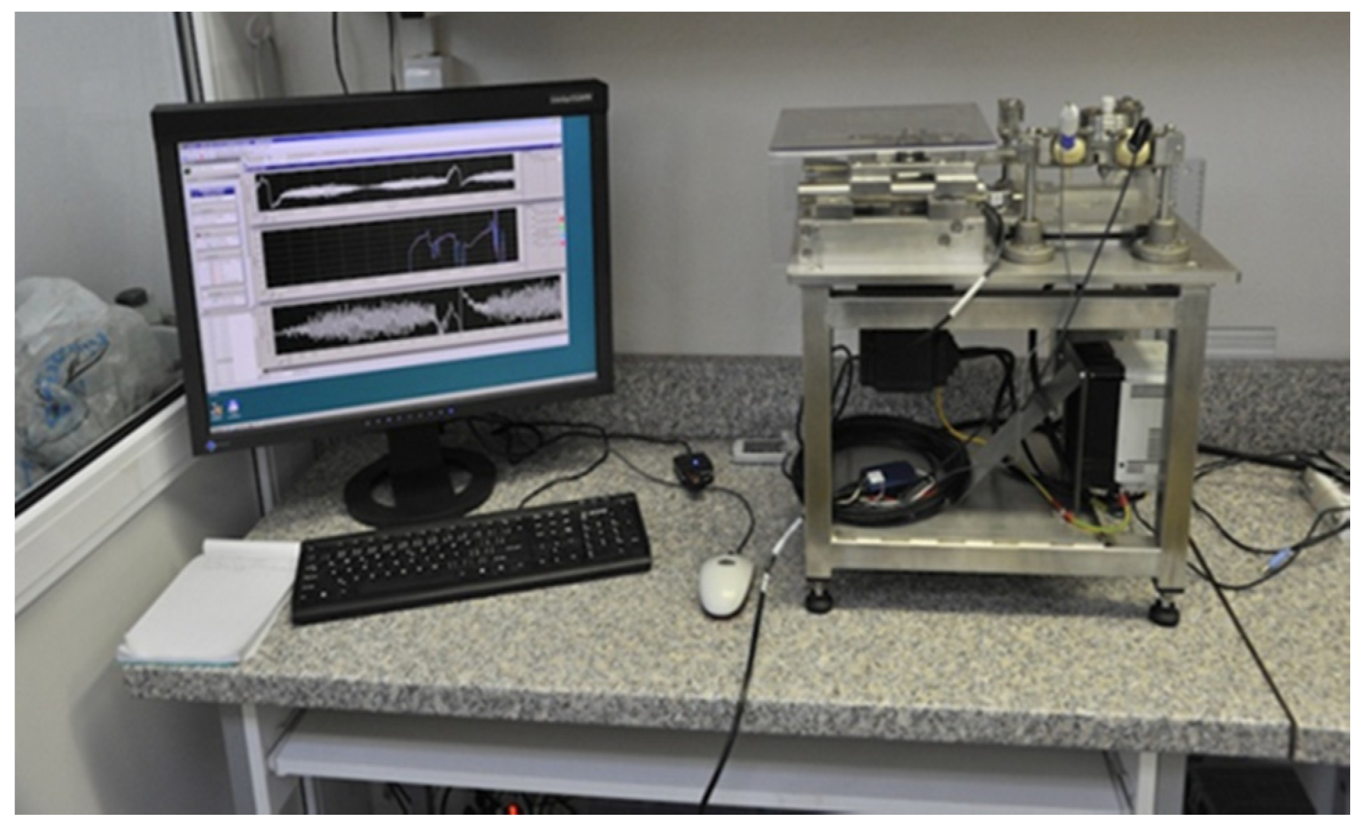
Tests were performed on a Potentiostat SP 150 device (Bio-Logic Science Instruments, Claix, France) and were processed using EC-Lab V10 software (version V10, Bio-Logic Science Instruments, Claix, France). A saturated calomel electrode (SCE) was used as the reference electrode, and platinum (Pt) was used as an auxiliary electrode. The start of the measurement procedure consisted of stabilizing the electrode potential Er (V) over a time interval of 15 min. The software recorded values every 5 s or 5 mV. The polarization ranged from −0.30 V against the free potential up to 1.00 V against the calomel electrode at a polarization rate of 1 mV/s. After the time sequence had elapsed, the values most closely related to the observed potential values were recorded. The resulting current densities with dependence on the inserted potential were plotted using semilogarithmic coordinates.
2.5. Testing of Wear Resistance of the Coatings
The erosive-wear resistance of the coatings was evaluated by a dry-pot wear test on the basis of the relative motion of the coating against an abrasive stored in a pin mill. The erosive dry-pot wear test was carried out on a laboratory test device (Figure 1), whereby the coating mounted on a driven holder was milled by an abrasive poured into a container with sample angles of 45° and 90°. The abrasive and conditions used were as follows: brown corundum; particle size: 0.75 mm; duration of the test: 8 h; sample speed: 1.74 m·s−1; depth of coating immersion in abrasive: 60 mm; wear track (8 h): 50 km.
The wear of the coatings was expressed by weight loss, measured every 60 min. The mass loss was converted to volume loss using the density of the coatings. The densities of the coatings were calculated on the basis of known densities of individual constituents and weight percentages of hard particles and matrices in coatings, as follows:
Density of WC-WB-Co coating: densityWC = 15.7 g·cm−3; densityWB = 15.3 g·cm−3; densityCo = 8.9 g·cm−3; volume portion of constituents (WC-WB-Co) of 60/30/10; resulting densityWC-WB-Co = 14.9 g·cm−3.
Density of WC-FeCrAl coating: densityWC = 15.7 g·cm−3; densityFeCrAl = 7.15 g·cm−3; volume portion of constituents (WC-FeCrAl) of 85/15; resulting densityWC-FeCrAl = 14.42 g·cm−3.
The abrasive wear test using abrasive cloth was realized on an APGi laboratory device, VEB, Leipzig, Germany (Figure 2). Abrasive cloth with grit sizes of #80 and #120 were used (load of 10 N, circumferential velocity of 0.33 m·s−1, and wear track of 40 m).
The results of the abrasive wear test using abrasive cloth were converted from mass loss (g) to wear rate (mm3/N·m) with the help of known wear track (m), load (N), and coating densities.
The adhesive wear of the coatings was evaluated by a sliding wear test (pin-on-disc) according to ISO 20808: 2016. The principle of the test is the contact and relative motion of a tungsten carbide ball with a coating, fixed on a rotating disk. The experiment was carried out on a prototype of a unique device for testing tribo-corrosive properties (Figure 3). This device allows for performing experiments in dry friction as well as corrosive environments. The adhesive wear test was performed in dry friction in atmosphere (ATM) and also in a 1 mol solution of NaCl (surface of the coatings: as-sprayed; load force: 1.5 N; linear speed: 0.02 m·s−1; stop condition: 60 min (track length: 72 m)).
3. Results and Discussion
The quality and selected properties of the coatings were determined under the given load conditions depending on the number of thermal cycles.
Microgeometry values point out on the quality of the coatings regarding remelting of powder particles, the powder grain size used, and the spraying parameters. The resulting microgeometry and application of the coating define whether subsequent coating finishing is necessary or not. From Table 5, it is clear that the coatings had a relatively low surface roughness; they can be used under as-sprayed conditions or can be grinded or lapped.
The measuring of surface roughness was only an informative measurement in terms of surface coating quality. If a coating is applied to a free surface, for example, the surface of rollers feeding textiles or metal sheets, it does not require grinding; if a coating is applied on some sealing surfaces, for example, ball valves, the coating must be grinded and lapped. It depends on the application of the coating.
The microhardness of the coatings is shown in Figure 4.
The values of the microhardness of the WC-FeCrAl coating ranged from 1050 to 1069 HV 0.1, and the microhardness values of the WC-WB-Co coating varied from 1221 to 1325 HV 0.1. Significant changes in the microhardness values of the coatings values were not observed. Because of the heterogeneous structure of the coatings and their high hardness, the variance in the hardness values of the measurements was relatively wide; therefore the changes in hardness in relation to the number of thermal cycles could be considered negligible.
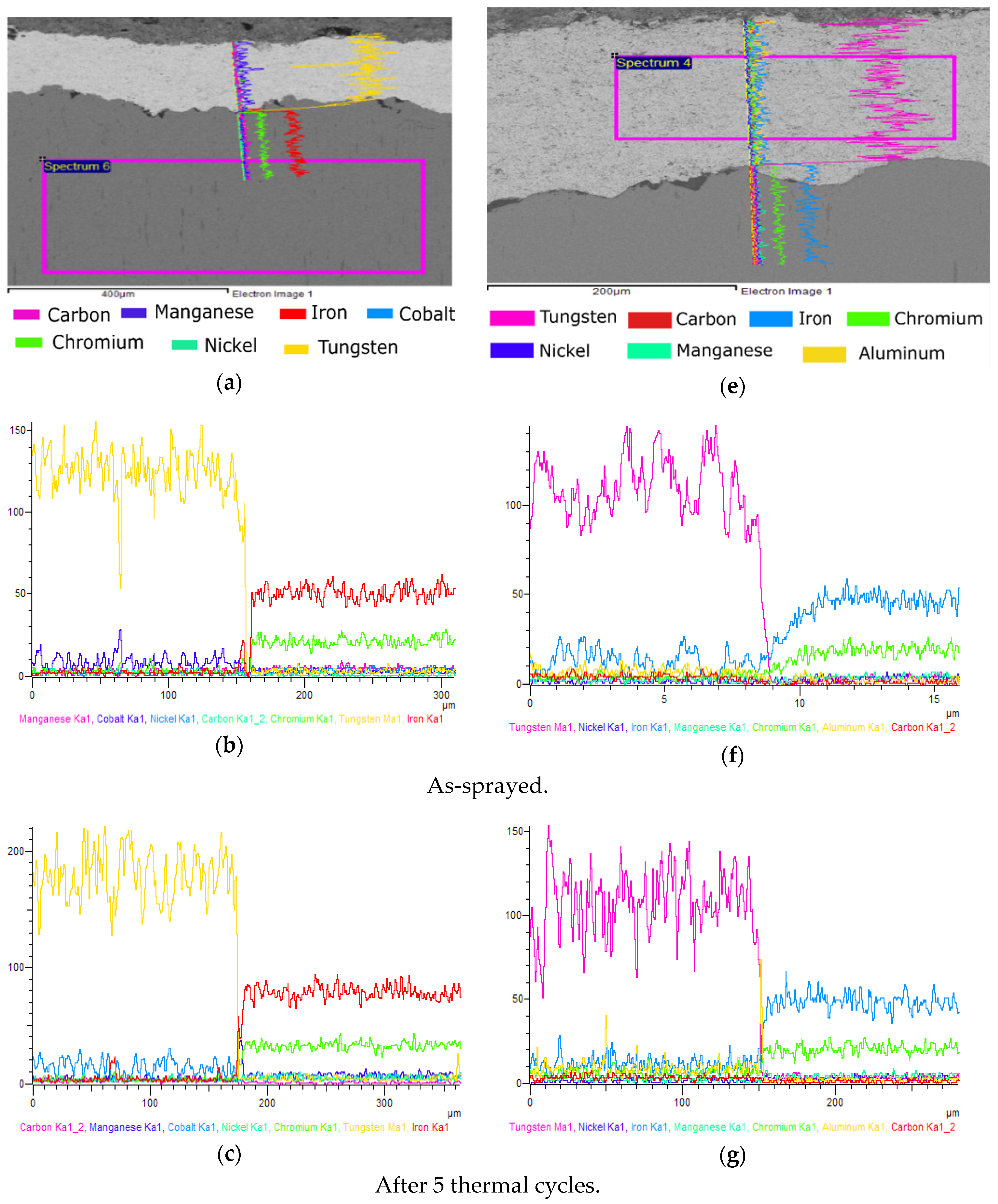
The chemical composition of the coatings was detected by EDX analysis. The content of individual elements in the coatings can be seen in Figure 5, Figure 6 and Figure 7. Figure 5 shows the chemical composition of the base material (wt. %) in the spectrum.
Figure 6 shows the detail of the microstructure of the WC-FeCrAl coating and EDX analysis of the particles and matrix.
In Figure 7 is shown the chemical composition and structure of the WC-WB-Co coating. Because of its heterogeneous structure—hard particles in a relatively soft matrix—a chemical analysis of both these regions was performed.
In Figure 8 is shown the line EDX analysis of the evaluated coatings with dependence on the number of thermal cycles.
Figure 8 shows the EDX measurement results, which analyzed the distribution of coatings’ main constituents at the substrate–coating interface. The scan position is marked by a straight line. The results showed that there were no changes in the chemical compositions of the coatings, as evident from EDX line scans, caused by thermal cyclic load.
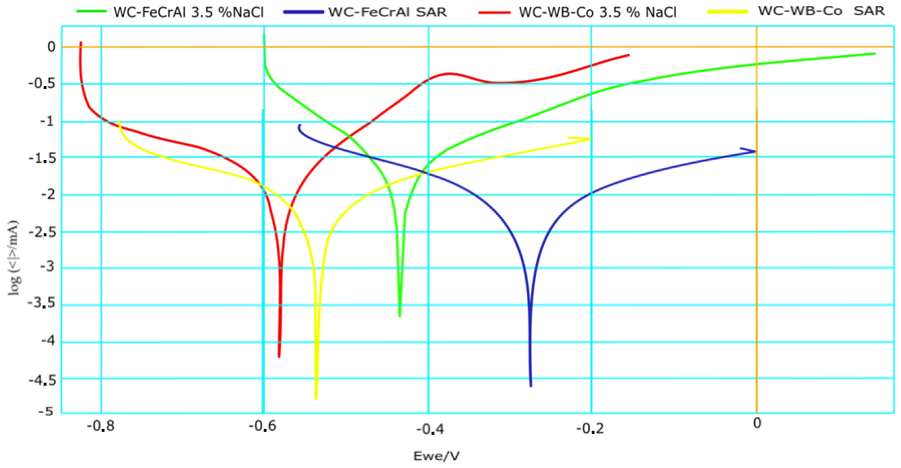
Using the Tafel polarization method, the current densities of the measured samples and the calculated corrosion rate of the evaluated coatings were determined. Potentiodynamic polarizing curves of exposed coatings can be seen in Figure 9. The corrosion potential and corrosion current of exposed samples in SAR solution and in 3.5% NaCl solution are shown in Table 6.
From the results, it can be concluded that the lowest current density was recorded for the WC-FeCrAl coating exposed in SAR solution. The highest current density was recorded for the WC-WB-Co coating exposed to 3.5% NaCl solution. Regarding the solution used, a higher corrosion aggressivity was shown in the 3.5% NaCl solution compared to SAR. Higher corrosion resistance in both testing solutions were shown for the WC-FeCrAl coating.
Figure 10 shows the volume loss of the coatings after the dry-pot wear test with sample angles of 45° and 90°, depending on the number of thermal cycles.
The results proved the high erosive-wear resistance of the coatings. Lower volume-loss values were recorded for the WC-FeCrAl coating mainly at a sample angle of 90°; at a sample angle of 45°, differences between the coatings became less pronounced. Thermally affected coatings (after 5 and 10 thermal cycles) showed higher wear resistance compared to as-sprayed coatings. Despite aggressive test conditions—high-speed and long-time-period tests—the volume loss of the coatings was relatively low, and there is only a small opportunity to compare the achieved results with other works because of a lack of test results for thermally sprayed coatings tested under dry-pot erosive test conditions. Some results can be found in the works of N. Ojala [35,36,37,38,39], but the authors often used slurry-pot erosive tests, for which the conditions were quite different. The low volume loss was the manifestation of good adhesion of the coatings to the substrate, and particularly between the particles and the matrix.
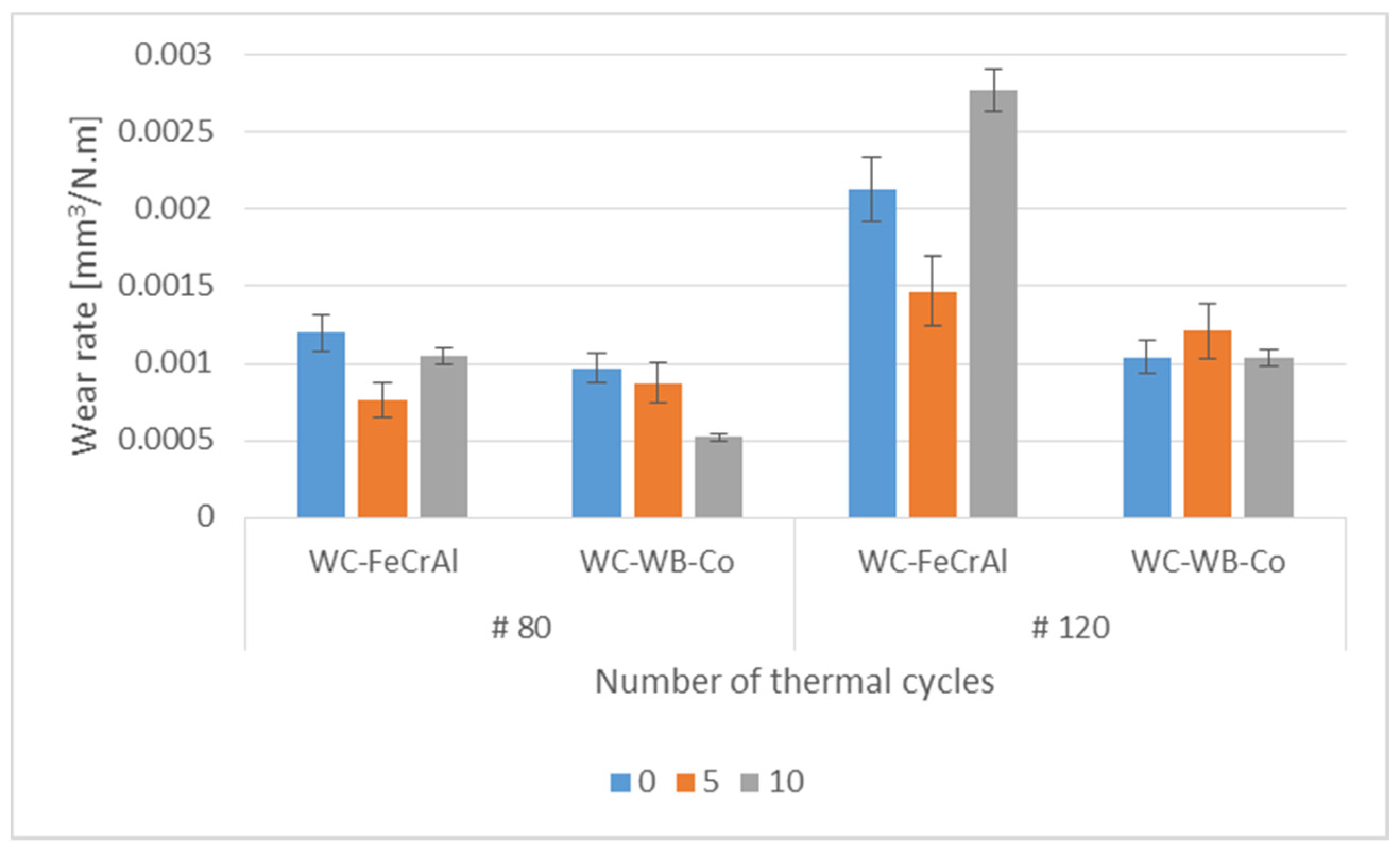
Figure 11 shows the wear rate of the coatings in the abrasive wear test using abrasive cloth.
From Figure 11, it can be stated that a higher wear resistance was shown by the WC-WB-Co coating. Differences in the wear rate using a smaller abrasive grit size (#120) were more pronounced. The smaller grit size of the abrasive (#120) was closer to the size of the WC particles and more intensively removed them, compared to the large abrasive grit size. Additionally, the number of grains in contact with the coating along the wear track was larger using the smaller grit size, and therefore differences between the coatings became more pronounced.
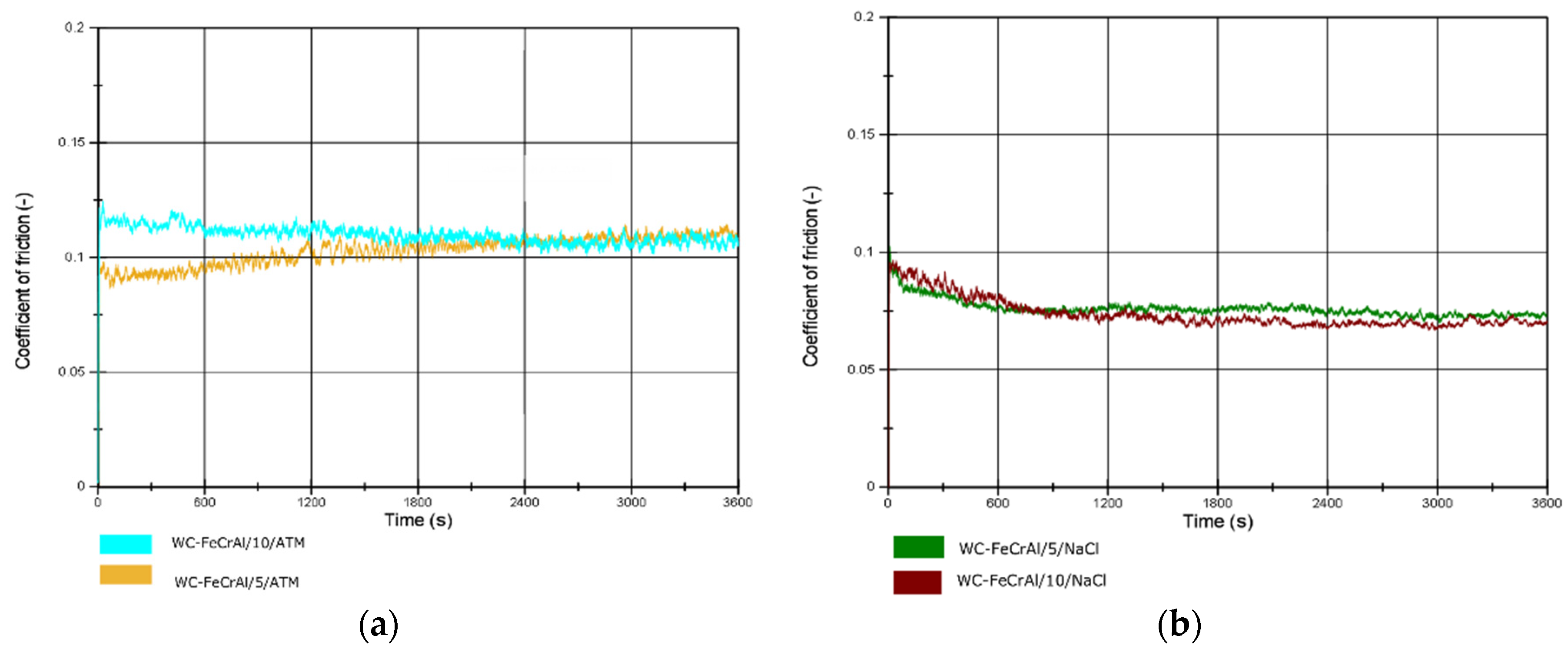
Figure 12 shows the course of the friction coefficient for the WC-FeCrAl coating during the pin-on-disc adhesion wear test in dry friction and in NaCl solution.
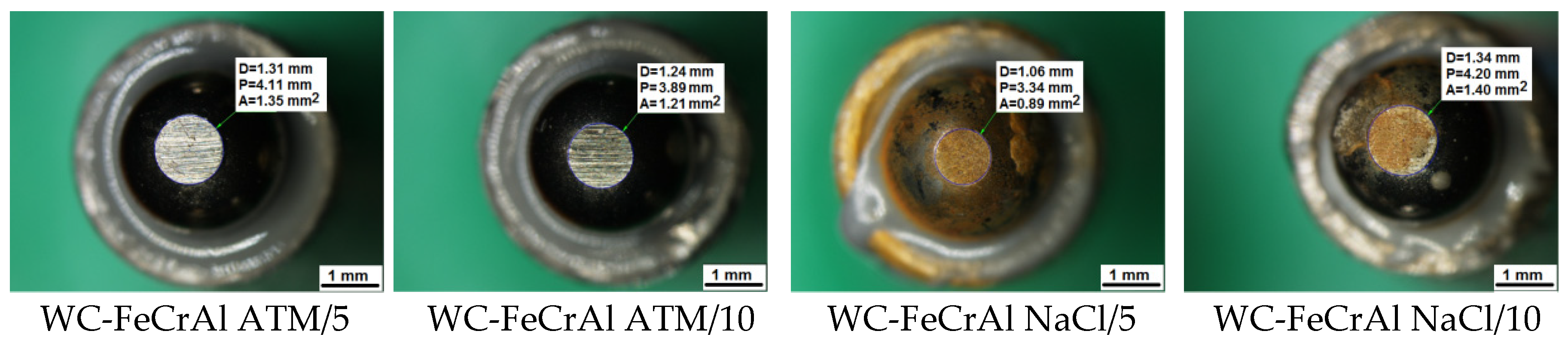
Figure 13 shows worn pins after the sliding wear test for the WC-FeCrAl coating.
Figure 14 shows the course of the friction coefficient for the WC-WB-Co coating during the pin-on-disc adhesion wear test in dry friction and in NaCl solution.
Figure 15 shows worn pins after the sliding wear test for the WC-WB-Co coating.
The friction coefficient in dry friction had a slightly increasing trend in both evaluated coatings, reaching a value of just above 0.1. In the corrosive solution, lower friction-coefficient values were measured with a decreasing tendency and steadied just below 0.1. In all cases, the pin was preferably worn, but the coating remained intact. The wear of the balls, expressed by the flat worn area, is given in Table 7.
The wear of the pins corresponded to the hardness of the coatings: the harder WC-WB-Co coating produced a larger wear of the pins.
The appearance of the surface of the coatings after the sliding wear test is shown in Figure 16.
From Figure 16, it is clear that no visible damage of the coatings in the wear track occurred. As a result of the mutual ratio of the hardness of the coating to the SiC pin, no significant wear track was created on the coatings after wear; only surface roughness peaks were slightly smoothed.
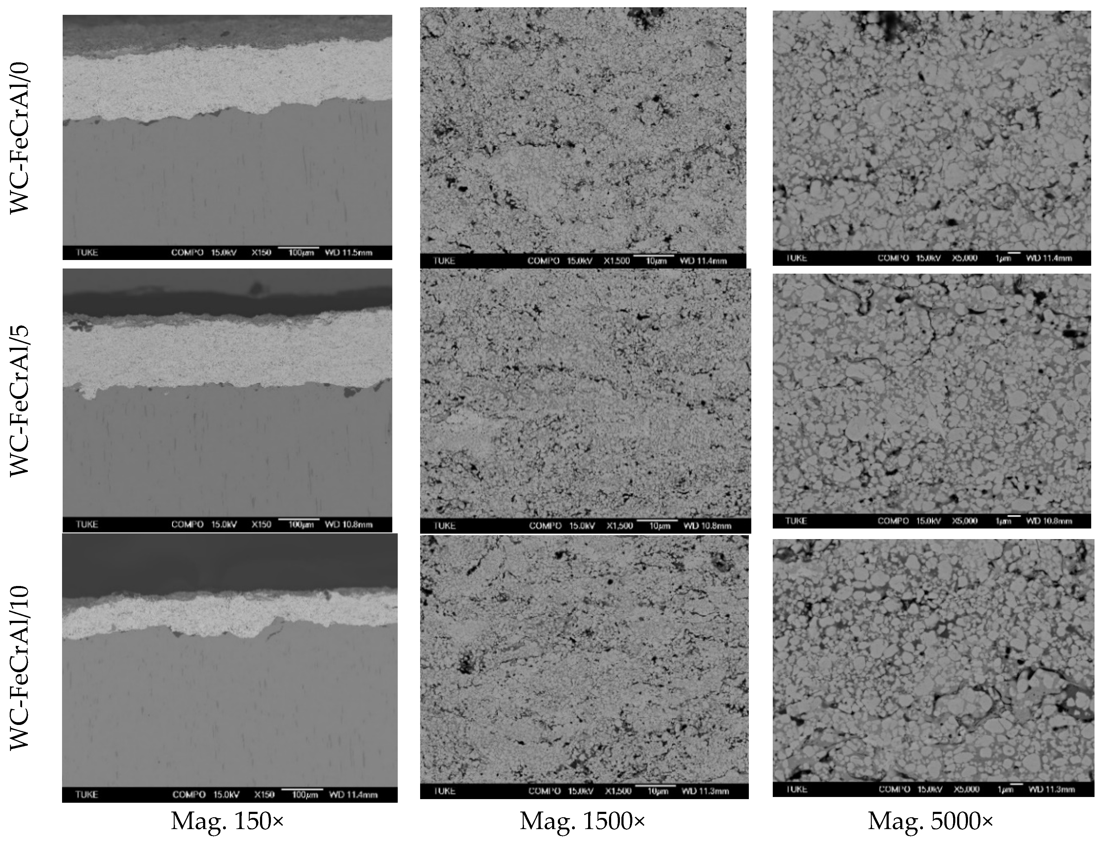
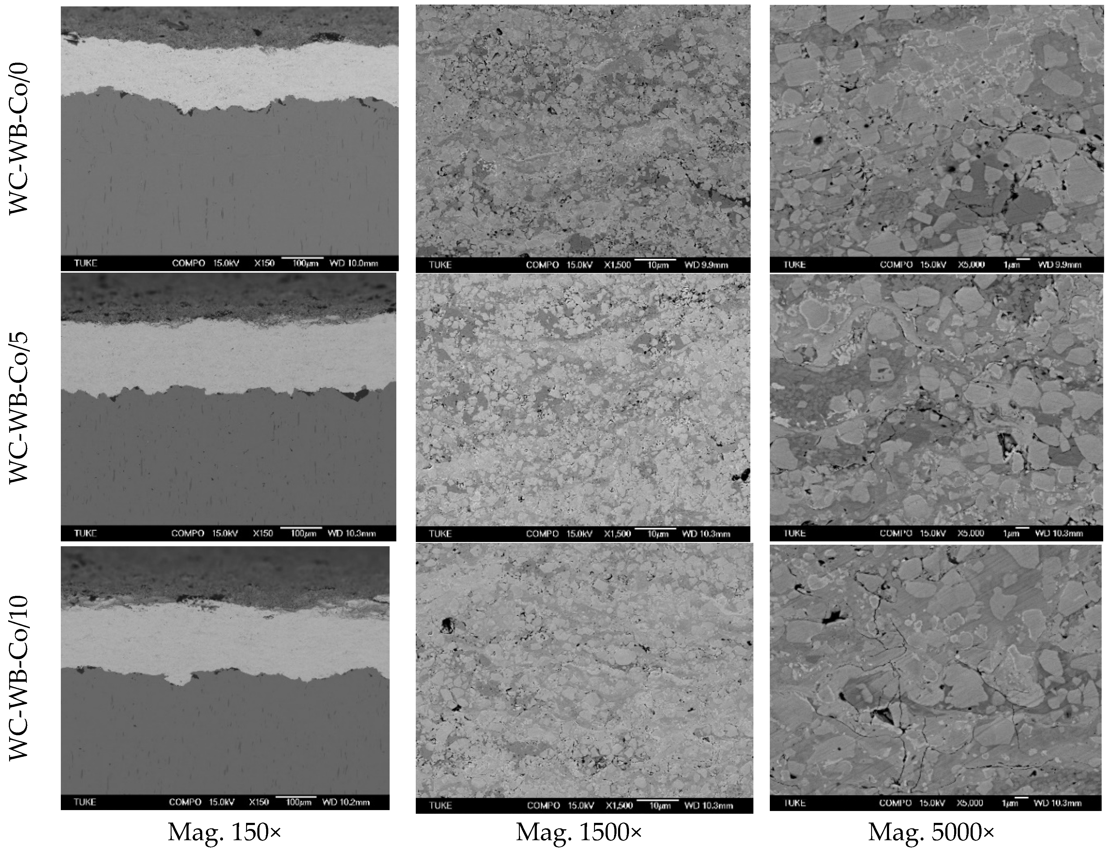
Figure 17 and Figure 18 show the WC-FeCrAl and WC-WB-Co coatings’ microstructures at various magnifications and numbers of thermal cycles.
From metallographic sections (Figure 17 and Figure 18) can be seen the increase in the oxidation layer at the expense of the thickness of the WC-FeCrAl coating, as a consequence of thermal cyclic loading. For the WC-WB-Co coating, this phenomenon was not recorded. Bolelli et al. [27] made a detailed analysis of the oxidation processes of the WC-FeCrAl and WC-CoCr coatings. Bolelli stated that, at 400°C, WC-FeCrAl coatings become entirely covered by a thin oxide layer. The oxide film thickens on WC particles, indicating a somewhat higher propensity of the particles towards oxidation at a high temperature, but the matrix is also oxidized: FeO and WO3 were detected on the coating surface. Between 400 and 500 °C, the WC-FeCrAl cermet composition experiences significant oxidation, although, at this temperature, the material is still a safe distance from the maximum of the first oxidation peak. Bolelli compared the oxidation of the WC-FeCrAl coating with that of the WC-CoCr coating. The latter showed less propensity for oxidation. On the basis of the study mentioned above, it can be supposed that exposure of the WC-FeCrAl coating at 600 °C for a longer period of time would result in total coating destruction.
The presence of cracks on the metallographic sections could be explained as a consequence of mixture events that can occur in coatings during thermal cyclic loading [6,8,12,16,17,25,26,27]:
- The CTE (coefficient of thermal expansion) of the WC-FeCrAl coating rises slightly with increasing temperature and thus increases the difference between the CTEs of the coating and the base material.
- At 400 °C, some of the WC-based coatings have intrinsic high-temperature brittleness.
- Re-crystallisation of the matrix and/or precipitation of η-phase carbides can occur around or above 600 °C [27].
- A brittle-to-ductile transition of the matrix can be expected at around 700 °C for bulk WC-Co-based hardmetals.
4. Conclusions
The present study was focused on determining the quality properties of two grades of thermally sprayed HVOF coatings. The WC-FeCrAl coating contained hard WC particles in an environmentally progressive FeCrAl matrix; the WC-WB-Co coating contained WC and WB hard particles in the Co matrix.
The experimental work led to the following conclusions:
- It confirmed the high hardness of both coatings, which is a prerequisite for their high wear resistance. The hardness of the WC-WB-Co coating (60/30/10; 90 wt. %WC and WB particles) was higher by 200 HV units compared to WC-FeCrAl (85/15; 85 wt. % WC) because of a higher proportion of hard particles in the soft binder matrix.
- In the erosive dry-pot wear test, both coatings showed excellent wear resistance; slightly higher volume loss of both coatings was detected at a sample angle of 90° as well as at both sample angles in the WC-WB-Co coating.
- In the abrasive test using abrasive cloth, the excellent wear resistance of both coatings was confirmed again, being slightly higher in the WC-WB-Co coating.
- The friction coefficient of the as-sprayed (non-grinded) coatings in dry friction as well as in the corrosive environment varied around 0.1.
- The corrosion resistance of the coatings was very similar but slightly higher in the WC-FeCrAl coating. Higher corrosion rates were recorded in the 3.5% NaCl solution against SAR.
- The cross-sectional microstructure of the coatings was characterized by the high density of the hard particles joined with the minimum amount of matrix (skeleton structure). In the WC-FeCrAl coating was recorded an increase in the oxidation layer as a consequence of thermal cyclic loading.
In view of the results, it is possible to state that the green carbide coating is an adequate alternative to conventional WC-based coatings, both in terms of hardness, resistance to contact friction, and corrosion resistance. From an environmental point of view, the WC-FeCrAl coating is a means to eliminate hazardous metals from the environment and human reach while preserving the excellent properties of conventional WC-based coatings.
Author Contributions
J.B. conducted the pin-on-disc test, the EDX analyses, and the analysis and interpretation of the results; A.G. conducted measurements of the hardness and the dry-pot erosive wear test; D.D. conducted measurements of the microgeometry; L.D. conducted the wear test using abrasive cloth; M.L. manufactured the test samples and conducted corrosion measurements.
Acknowledgments
This work was supported by the Ministry of Education, Science, Research and Sport of the Slovak Republic (VEGA 1/0424/17, KEGA Grant 059TUKE-4/2016).
Conflicts of Interest
The authors declare no conflict of interest.
References
- Nahvi, S.M.; Jafari, M. Microstructural and mechanical properties of advanced HVOF-sprayed WC-based cermet coatings. Surf. Coat. Technol. 2016, 286, 95–102. [Google Scholar] [CrossRef]
- Oksa, M.; Turunen, E.; Suhonen, T.; Varis, T.; Hannula, S.-P. Optimization and Characterization of High Velocity Oxy-fuel Sprayed Coatings: Techniques, Materials, and Applications. Coatings 2011, 1, 17–52. [Google Scholar] [CrossRef]
- Brezinová, J.; Guzanová, A.; Egri, M.; Malejčík, J. Evaluation of thermal sprayed coatings properties in terms of erosive wear. Chem. Listy 2011, 105, 775–776. [Google Scholar]
- Viňáš, J.; Brezinová, J.; Guzanová, A. Tribological properties of selected ceramic coatings. J. Adhes. Sci. Technol. 2013, 27, 196–207. [Google Scholar] [CrossRef]
- Brezinová, J.; Guzanová, A.; Draganovská, D.; Bronček, J. Quality Evaluation of HVOF Coatings on the Basis of WC-Co in Tribocorrosive Conditions. Mater. Sci. Forum 2015, 811, 63–66. [Google Scholar] [CrossRef]
- Amiriyan, M.; Blais, C.; Savoie, S.; Schulz, R.; Gariépy, M.; Alamdari, H.D. Mechanical Behavior and Sliding Wear Studies on Iron Aluminide Coatings Reinforced with Titanium Carbide. Metals 2017, 7, 177. [Google Scholar] [CrossRef]
- Xie, M.; Lin, Y.; Ke, P.; Wang, S.; Zhang, S.; Zhne, Z.; Ge, L. Influence of Process Parameters on High Velocity Oxy-Fuel Sprayed Cr3C2-25%NiCr Coatings. Coatings 2017, 7, 98. [Google Scholar] [CrossRef]
- Yao, H.; Zhou, Z.; Wang, L.; Tan, Z.; He, D.; Zhao, L. Thermal Conductivity and Wear Behavior of HVOF-Sprayed Fe-Based Amorphous Coatings. Coatings 2017, 7, 173. [Google Scholar] [CrossRef]
- Li, T.; Liu, Y.; Liu, B.; Guo, W.; Xu, L. Microstructure and Wear Behavior of FeCoCrNiMo0.2 High Entropy Coatings Prepared by Air Plasma Spray and the High Velocity Oxy-Fuel Spray Processes. Coatings 2017, 7, 151. [Google Scholar] [CrossRef]
- Matikainen, V.; Niemi, K.; Koivuluoto, H.; Vuoristo, P. Abrasion, Erosion and Cavitation Erosion Wear Properties of Thermally Sprayed Alumina Based Coatings. Coatings 2014, 4, 18–36. [Google Scholar] [CrossRef] [Green Version]
- Metsäjoki, J.; Oksa, M.; Tuurna, S.; Lagerbom, J.; Virta, J.; Yli-Olli, S.; Suhonen, T. Tailoring a High Temperature Corrosion Resistant FeNiCrAl for Oxy-Combustion Application by Thermal Spray Coating and HIP. Coatings 2015, 5, 709–723. [Google Scholar] [CrossRef]
- Zhou, W.; Zhou, K.; Li, Y.; Deng, C.; Zeng, K. High temperature wear performance of HVOF-sprayed Cr3C2-WC-NiCoCrMo and Cr3C2-NiCr hardmetal coatings. Appl. Surf. Sci. 2017, 416, 33–44. [Google Scholar] [CrossRef]
- Thakur, L.; Arora, N.; Jayaganthan, R.; Sood, R. An investigation on erosion behavior of HVOF sprayed WC-CoCr coatings. Appl. Surf. Sci. 2011, 258, 1225–1234. [Google Scholar] [CrossRef]
- Murry, J.W.; Ang, A.S.M.; Pala, Z.; Shaw, E.C.; Hussain, T. Suspension High Velocity Oxy-Fuel (SHVOF)-Sprayed Alumina Coatings: Microstruture, Nanoindentation and Wear. J. Therm. Spray Technol. 2016, 25, 1700–1710. [Google Scholar] [CrossRef]
- Cui, S.Y.; Miao, Q.; Liang, W.P.; Huang, B.Z.; Ding, Z.; Chen, E.W. Slurry Erosion Behavior of F6NM Stainless Steel and High-Velocity Oxygen Fuel-Sprayed WC-10Co-4Cr Coating. J. Therm. Spray Technol. 2017, 26, 473–482. [Google Scholar] [CrossRef]
- Fossati, A.; Ferdinando, M.D.; Lanacchi, A.; Scrivani, A.; Giolli, C.; Bardi, U. Improvement of the Oxidation Resistance of CoNiCrAlY Bond Coats Sprayed by High Velocity Oxygen-Fuel onto Nickel Superalloy Substrate. Coatings 2011, 8, 3–16. [Google Scholar] [CrossRef]
- Milanti, A.; Koivuluoto, H.; Vuoristo, P.; Bolelli, G.; Bozza, F.; Lusvarghi, L. Microstructural Characteristics and Tribological Behavior of HVOF-Sprayed Novel Fe-Based Alloy Coatings. Coatings 2014, 4, 98–120. [Google Scholar] [CrossRef]
- Jadidi, M.; Moghtadernejad, S.; Dolatabadi, A. A Comprehensive Review on Fluid Dynamics and Transport of Suspension/Liquid Droplets and Particles in High-Velocity Oxygen-Fuel (HVOF) Thermal Spray. Coatings 2015, 5, 576–645. [Google Scholar] [CrossRef]
- Öz, A.; Gürbüz, H.; Yakut, A.K.; Sağiroğlu, S. Braking performance and noise in excessive worn brake discs coated with HVOF thermal spray process. J. Mech. Sci. Technol. 2017, 31, 535–543. [Google Scholar] [CrossRef]
- Wang, X.; Ouyang, T.; Duan, X.; Kr, C.; Zhang, X.; Min, J.; Li, A.; Guo, W.; Cheng, X. Improved Solar Absorptance of WC/Co Solar Selective Absorbing Coating with Multimodal WC Particles. Metals 2017, 7, 137. [Google Scholar] [CrossRef]
- Yury, K.; Filippov, M.; Makarov, A.; Malygina, I.; Soboleva, N.; Fantozzi, D.; Andrea, M.; Koivuluoto, H.; Vuoristo, P. Arc-Sprayed Fe-Based Coatings from Cored Wires for Wear and Corrosion Protection in Power Engineering. Coatings 2018, 8, 71. [Google Scholar] [CrossRef]
- Zhuang, Q.; Zhang, P.; Li, M.; Yan, H.; Yu, Z.; Lu, Q. Microstructure, Wear Resistance and Oxidation Behavior of Ni-Ti-Si Coatings Fabricated on Ti6Al4V by Laser Cladding. Materials 2017, 10, 1248. [Google Scholar] [CrossRef] [PubMed]
- Löbel, M.; Lindner, T.; Mehner, T.; Lampke, T. Microstructure and Wear Resistance of AlCoCrFeNiTi High-Entropy Alloy Coatings Produced by HVOF. Coatings 2017, 7, 144. [Google Scholar] [CrossRef]
- Huang, B.; Song, C.; Liu, Y.; Gui, Y. Microstructure Characterization and Wear-Resistant Properties Evaluation of an Intermetallic Composite in Ni–Mo-Si System. Materials 2017, 10, 130. [Google Scholar] [CrossRef] [PubMed]
- Bolelli, G.; Börner, T.; Bozza, F.; Cannillo, V.; Cirillo, G.; Lusvarghi, L. Cermet coatings with Fe-based matrix as alternative to WC-CoCr: Mechanical and tribological behaviours. Surf. Coat. Technol. 2012, 206, 4079–4094. [Google Scholar] [CrossRef]
- Bolelli, G.; Börner, T.; Milanti, A.; Lusvarghi, L.; Laurila, J.; Koivuluoto, H.; Niemi, K.; Vuoristo, P. Tribological behavior of HVOF- and HVAF-sprayed composite coatings based on Fe-Alloy + WC–12% Co. Surf. Coat. Technol. 2014, 248, 104–112. [Google Scholar] [CrossRef]
- Bolelli, G.; Hulka, I.; Koivuluoto, H.; Lusvarghi, L.; Milanti, A. Properties of WC–FeCrAl coatings manufactured by different high velocity thermal spray processes. Surf. Coat. Technol. 2014, 247, 74–89. [Google Scholar] [CrossRef]
- Milanti, A.; Matikainen, V.; Bolelli, G.; Koivuluoto, H.; Lusvarghi, L.; Vuoristo, P. Microstructure and Sliding Wear Behavior of Fe-Based Coatings Manufactured with HVOF and HVAF Thermal Spray Processes. J. Therm. Spray Technol. 2016, 25, 1040–1055. [Google Scholar] [CrossRef]
- Bouaricha, S.; Legoux, J.-G.; Marple, B.-R. HVOF Coatings Properties of the Newly Thermal Spray Composition WC-WB-Co; National Research Council Canada, Industrial Materials Institute: Ottawa, ON, Canada, 2004. [Google Scholar]
- Hulka, I.; Utu, D.; Serban, V.-A.; Dan, M.-L.; Matikainen, V.; Vuoristo, P. Corrosion Behavior of WC-FeCrAl Coatings Deposited by HVOF and HVAF Thermal Spraying Methods. Chem. Bull. Politeh. Univ. Timis. Ser. Chem. Environ. Eng. 2016, 61, 1–6. [Google Scholar]
- Brezinová, J.; Guzanová, A.; Draganovská, D.; Maruschak, P.; Landová, M. Study of selected properties of thermally sprayed coatings containing WC and WB hard particles. Acta Mech. Autom. 2016, 10, 296–299. [Google Scholar] [CrossRef]
- Landová, M.; Brezinová, J. Determination of selected properties and fracture toughness of HVOF coatings. Koroze Ochr. Mater. 2016, 60, 128–131. [Google Scholar] [CrossRef]
- Brezinová, J.; Guzanová, A.; Egri, M. Change in properties of HVOF coatings under conditions of thermal cyclic loading. Chem. Listy 2012, 106, 383–386. [Google Scholar]
- Brezinová, J.; Guzanová, A. Possibilities of utilization high velocity oxygen fuel (HVOF) coatings in conditions of thermal cyclic loading. Metalurgija 2012, 15, 211–215. [Google Scholar]
- Haiko, O.; Somani, M.; Porter, D.; Kantanen, P.; Kömi, J.; Ojala, N.; Heino, V. Comparison of impact-abrasive wear characteristics and performance of direct quenched (DQ) and direct quenched and partitioned (DQ&P) steels. Wear 2018, 400–401, 21–30. [Google Scholar] [CrossRef]
- Ojala, N.; Valtonen, K.; Minkkinen, J.; Kuokkala, V.-T. Edge and particle embedment effects in low- and high-stress slurry erosion wear of steels and elastomers. Wear 2017, 388–389, 126–135. [Google Scholar] [CrossRef]
- Valtonen, K.; Ratia, V.; Ojala, N.; Kuokkala, V.-T. Comparison of laboratory wear test results with the in-service performance of cutting edges of loader buckets. Wear 2017, 388–389, 93–100. [Google Scholar] [CrossRef]
- Ojala, N.; Valtonen, K.; Antikainen, A.; Kemppainen, A.; Minkkinen, J.; Oja, O.; Kuokkala, V.-T. Wear performance of quenched wear resistant steels in abrasive slurry erosion. Wear 2016, 354–355, 21–31. [Google Scholar] [CrossRef]
- Ojala, N.; Valtonen, K.; Heino, V.; Kallio, M.; Aaltonen, J.; Siitonen, P.; Kuokkala, V.-T. Effects of composition and microstructure on the abrasive wear performance of quenched wear resistant steels. Wear 2014, 317, 225–232. [Google Scholar] [CrossRef]
Figure 1.
(a) Fixing of test samples in the testing device; (b) scheme of contact geometry.

Figure 2.
Scheme of APGi test device with abrasive cloth.

Figure 3.
Prototype of a unique device for testing tribo-corrosive properties.

Figure 4.
Microhardness of the coatings.

Figure 5.
(a) SEM image of base material and coating; (b) EDS spectrum of selected area of base material.
Figure 5.
(a) SEM image of base material and coating; (b) EDS spectrum of selected area of base material.

Figure 6.
(a) SEM image of WC-FeCrAl coating; (b) EDS spectrum of FeCrAl matrix; (c) EDS spectrum of WC particle.
Figure 6.
(a) SEM image of WC-FeCrAl coating; (b) EDS spectrum of FeCrAl matrix; (c) EDS spectrum of WC particle.

Figure 7.
(a) SEM image of WC-WB-Co coating; (b) EDS spectrum of WC particle; (c) EDS spectrum of Co matrix.
Figure 7.
(a) SEM image of WC-WB-Co coating; (b) EDS spectrum of WC particle; (c) EDS spectrum of Co matrix.

Figure 8.
(a) SEM image of WC-WB-Co coating; EDX line scan of (b) as-sprayed WC-WB-Co coating; (c) after 5 thermal cycles; (d) after 10 thermal cycles; (e) SEM image of WC-FeCrAl coating; EDX line scan of (f) as-sprayed WC-FeCrAl coating; (g) after 5 thermal cycles; (h) after 10 thermal cycles.
Figure 8.
(a) SEM image of WC-WB-Co coating; EDX line scan of (b) as-sprayed WC-WB-Co coating; (c) after 5 thermal cycles; (d) after 10 thermal cycles; (e) SEM image of WC-FeCrAl coating; EDX line scan of (f) as-sprayed WC-FeCrAl coating; (g) after 5 thermal cycles; (h) after 10 thermal cycles.


Figure 9.
Potentiodynamic polarizing curves of exposed samples.

Figure 10.
Volume loss of the coatings at particular sample angles.

Figure 11.
Wear rate of the coatings with dependence on abrasive cloth grit size.

Figure 12.
WC-FeCrAl coating: (a) friction coefficient in dry friction, and (b) friction coefficient in sodium chloride (NaCl) solution.
Figure 12.
WC-FeCrAl coating: (a) friction coefficient in dry friction, and (b) friction coefficient in sodium chloride (NaCl) solution.

Figure 13.
Pins after sliding wear test of the WC-FeCrAl in dry atmosphere (ATM) and in sodium chloride (NaCl) solution.
Figure 13.
Pins after sliding wear test of the WC-FeCrAl in dry atmosphere (ATM) and in sodium chloride (NaCl) solution.

Figure 14.
WC-WB-Co coating: (a) friction coefficient in dry friction, and (b) friction coefficient in sodium chloride (NaCl) solution.
Figure 14.
WC-WB-Co coating: (a) friction coefficient in dry friction, and (b) friction coefficient in sodium chloride (NaCl) solution.

Figure 15.
Pins after sliding wear test of the WC-WB-Co in dry atmosphere (ATM) and in sodium chloride (NaCl) solution.
Figure 15.
Pins after sliding wear test of the WC-WB-Co in dry atmosphere (ATM) and in sodium chloride (NaCl) solution.

Figure 16.
Appearance of coatings’ surfaces in and out of wear track (SEM).

Figure 17.
Microstructure of WC-FeCrAl coating.

Figure 18.
Microstructure of WC-WB-Co coating.


Table 1.
Chemical composition of base material (wt. %).
| Element | C | Si | Mn | P | S | Cr | Mo | Ni | Fe |
|---|---|---|---|---|---|---|---|---|---|
| AISI 316L | 0.07 | 1 | 2 | 0.4 | 0.03 | 16.5–18.5 | 2–2.5 | 10.5–13.5 | Bal. |
Table 2.
Chemical composition of feedstock powders (wt. %).
| Element | C | Fe | Cr | Al | B | W | Co |
|---|---|---|---|---|---|---|---|
| WC-FeCrAl | 5.4–5.9 | 10–12 | 2.5–3.8 | 0.6–1.2 | - | Bal. | - |
| WC-WB-Co | 3.5–4.0 | - | - | - | 1.5–2.5 | Bal. | 9–11 |
Table 3.
Spraying parameters.
| Nozzle diameter | 25.4 mm |
| Kerosene flow | 6.0 g·h−1/22.7 l·h−1 |
| Oxygen flow | 800 l·min−1 |
| Stand-off distance | 380 mm |
| Particles’ velocity | 800 m·s−1 |
| Spraying power | 5 kg·h−1 |
Table 4.
Chemical composition of simulated acid rain (SAR).
| Compound | Solution Content (mmol dm−3) | Molar Mass (g mol−1) | Solution Content (g dm−3) |
|---|---|---|---|
| HNO3 | 0.01 | 63.0129 | 0.00063 |
| NaCl | 1 | 58.443 | 0.058 |
| (NH4)2SO4 | 1 | 132.14 | 0.132 |
Table 5.
Microgeometry and thickness of the coatings.
| Coating | Ra (µm) | Rz (µm) | Thickness (µm) |
|---|---|---|---|
| WC-FeCrAl | 4.32 ± 0.28 | 24.25 ± 1.52 | 160 ± 11 |
| WC-WB-Co | 4.73 ± 0.31 | 27.25 ± 1.93 | 154 ± 9 |
Table 6.
Values of corrosion potential, current density, and slopes of cathode and anode dependence.
Table 6.
Values of corrosion potential, current density, and slopes of cathode and anode dependence.
| Testing Solution | 3.5% NaCl | SAR | ||
|---|---|---|---|---|
| Coating | WC-FeCrAl | WC-WB-Co | WC-FeCrAl | WC-WB-Co |
| Ecorr (mV) | −432.876 | −582.858 | −276.291 | −532.463 |
| icorr (µA) | 18.561 | 18.735 | 6.328 | 7.71 |
| βc (mV) | 121.9 | 310.8 | 277.8 | 309.9 |
| βa (mV) | 193.2 | 149.8 | 309.8 | 350.4 |
Table 7.
Wear of the balls (mm3).
| Number of Thermal Cycles | ATM | NaCl | ||
|---|---|---|---|---|
| 5 | 10 | 5 | 10 | |
| WC-FeCrAl | 0.049134 | 0.039404 | 0.021236 | 0.052873 |
| WC-WB-Co | 0.02905 | 0.042754 | 0.040063 | 0.057545 |
© 2018 by the authors. Licensee MDPI, Basel, Switzerland. This article is an open access article distributed under the terms and conditions of the Creative Commons Attribution (CC BY) license (http://creativecommons.org/licenses/by/4.0/).
Share and Cite
MDPI and ACS Style
Brezinová, J.; Landová, M.; Guzanová, A.; Dulebová, Ľ.; Draganovská, D. Microstructure, Wear Behavior and Corrosion Resistance of WC-FeCrAl and WC-WB-Co Coatings. Metals 2018, 8, 399. https://doi.org/10.3390/met8060399
AMA Style
Brezinová J, Landová M, Guzanová A, Dulebová Ľ, Draganovská D. Microstructure, Wear Behavior and Corrosion Resistance of WC-FeCrAl and WC-WB-Co Coatings. Metals. 2018; 8(6):399. https://doi.org/10.3390/met8060399
Chicago/Turabian StyleBrezinová, Janette, Mariana Landová, Anna Guzanová, Ľudmila Dulebová, and Dagmar Draganovská. 2018. "Microstructure, Wear Behavior and Corrosion Resistance of WC-FeCrAl and WC-WB-Co Coatings" Metals 8, no. 6: 399. https://doi.org/10.3390/met8060399
Note that from the first issue of 2016, this journal uses article numbers instead of page numbers. See further details here.