Manufacturability of Overhanging Holes Using Electron Beam Melting


1
Industrial Engineering Department, King Saud University, Riyadh 11421, Saudi Arabia
2
Princess Fatima Alnijiris’s Research Chair for Advanced Manufacturing Technology (FARCAMT Chair), Advanced Manufacturing Institute, King Saud University, Riyadh 11421, Saudi Arabia
*
Author to whom correspondence should be addressed.
Metals 2018, 8(6), 397; https://doi.org/10.3390/met8060397
Submission received: 15 April 2018
/
Revised: 22 May 2018
/
Accepted: 24 May 2018
/
Published: 30 May 2018
Abstract
:This study aims to investigate the manufacturability of overhang round holes with and without support. The experiments were conducted by electron beam melting (EBM) using a Ti6Al4V powder. A large number of overhanging holes with and without support were fabricated and evaluated. The geometrical accuracy, mechanical properties, and microstructures were utilized as a measure of the process performance. It was demonstrated that overhanging features can be built successfully without support up to a certain dimension (or threshold value). Beyond that value, a minimal support structure can be employed to achieve the most suitable trade-off between production time, cost, and accuracy.
1. Introduction
Additive manufacturing (AM), which comprises a group of different technologies, involves the fabrication of parts by adding materials in a layer-by-layer fashion [1,2]. AM can also be referred to as additive fabrication, direct digital manufacturing, rapid manufacturing, layer manufacturing, rapid prototyping, or solid freeform fabrication [3]. Indeed, there are many AM technologies, which can be classified depending on the baseline technology (e.g., laser-based technology, extrusion-based technology and printer technology), or raw material (such as solid, liquid or powder-based materials), etc. [4,5]. Among the existing AM processes, electron beam melting (EBM) is one of the most recent and promising forms of technology that allows the fabrication of complex three-dimensional (3D) objects directly from metal powder. It possesses numerous applications in high performance industries such as in the biomedical [6,7] and aerospace [8] fields. It is more effective when complex parts are manufactured in low volumes and conventional processing by machining, casting, etc., would result in higher lead-time and material wastage. EBM can be defined as a powder-bed-fusion AM process in which a fully solid part is directly fabricated in layer-by-layer manner from a computer-aided design (CAD) model. It can successfully build completely dense parts with mechanical properties that are similar to or even better than parts manufactured by traditional manufacturing. However, it needs additional structures known as supports, especially during the fabrication of overhanging surfaces. These are needed to hold the part firmly as well as to minimize geometrical distortion, warping, etc., by conducting the excess heat away from the part. Ideally, the sintered powder around the part could act as support in powder-based AM processes, thus dismissing the need for external support structures. As a matter of fact, sintered powder is not sufficient to support the melted metal because it is not thermally conductive, and in turn leads to dross formation, distortions, and warping [4,9,10,11]. Therefore, the importance of support structures is emphasized, especially in cases where even optimum orientation cannot produce accurate overhanging features [12,13,14].
An overhanging surface is defined as a part or a subpart that is built by AM and is not supported during the building process either by a substrate or by a solidified material on the bottom side [15]. Many overhang surface geometries can be designed and fabricated using AM [10,11,16,17,18,19,20]. They include ledge overhang, concave radii overhang, convex curve overhang, angle surface overhang, bridge overhang, hole overhang, and so on. Round holes are considered as an overhang surface because they are built without solid support. Round holes are one of the fundamental and most important overhang features in AM. The accuracy, surface quality, and mechanical strength are important issues in these features because they are usually used as channels in order to maintain the required amount of fluid flow and connect the fabricated components. Typically, a support structure is needed to build the hollow cylinder, which adds to cost and post-processing operations. Round holes are features, which are analogous to self-supporting surfaces because each layer is supported by the previous one and only small portion on the top is supported by the sintered powder.
Support structures can be identified as a non-functional frame, which is fabricated in conjunction with the functional part and removed after the AM is accomplished [21]. The principal objectives of support structures in AM are the prevention of part curling, distortion, sagging, cracks, and shrinkage and/or other deformations resulting from thermal stresses, as well as anchoring of part on the building platform [11]. Moreover, they help to conveniently remove the bottom of the fabricated part from the platform as well as strengthen thin and tall parts during the building process. Thus, it can be inferred that support structures cannot be avoided, although they pose many challenges such as [11,21]:
- Increased fabrication time and higher material requirements.
- Additional effort and complex process in designing support. Commercial software is capable, but often it is not sufficient.
- Support structures have to be taken off after completion of part building, which further increases the overall time and effort.
The presence of support structures increases the part building time in conjunction with the time and complexity of post-processing operations. Indeed, the elimination or even the minimization of support structures can enhance the efficiency and effectiveness of the AM process [9,10,11,24,25]. Accordingly, the appropriate design guidelines for overhanging surfaces and geometrical design of support structures can play a significant role to improve the viability and efficiency of metallic parts fabricated by EBM. Therefore, the primary goal in this work is to minimize the application of unnecessary support structures in overhang round holes. For this reason, a number of overhang holes with and without support structures have been fabricated, and a segmentation strategy has been proposed to optimize the support structure.
2. Literature Survey
Numerous research efforts can be identified which have paid attention to the minimization or elimination of the use of support structures. One of the most effective ways of lessening the use of the support and its associated cost is the optimum orientation of the part on the building platform [10,11,26]. The application of topology optimization can also be utilized to create a lightweight design that meets the support-free requirement [27,28]. Additionally, many research studies which have developed design rules for self-supporting overhangs can be found in the literature [10,15,17,29,30,31,32].
The hole is one of the most important forms of overhang geometry and may involve significant distortions after AM. For example, an appreciable deformation was observed by Thomas [17], for the round holes fabricated using support structures by selective laser sintering. This investigation also revealed the limits of the self-supporting hole diameter. Many researchers have also dealt with the performance of the EBM process for producing overhang surfaces. In an effort to develop design rules for the EBM process, Vayre et al. [33], investigated the manufacturing constraints i.e., removal of unbound powder and the need for supporting structures in the EBM process. The authors studied the effect of the duration as well as the cross section area and its type on the depth of the removed powder. They also evaluated the distortion level of the overhang surfaces in different orientation angles and assessed the effect of the support. The distance between the start plate and the first layer and the effect of support structure density was also examined with respect to the fabricated overhang surface quality. Vora et al., [34], demonstrated the capabilities of the EBM process for building overhang surfaces without support structures by using the blended powder approach. In fact, Al-Si and Ti64-Cu alloys were successfully processed, and unsupported overhang surfaces with dimensions of 5 mm were produced without warping. When compared to other benchmarking results of Ti64-Cu parts that were fabricated by EBM, the height of warp was reduced from 2.7 mm to 0.3 mm (88%). Moreover, Cheng et al. [20] developed a 3D finite element thermo-mechanical model to simulate temperature and stress fields for building Ti6Al4V simple overhang by EBM in order to examine the root cause of overhang warping. They found that poor thermal conductivity of powder resulted in higher temperatures and lagging heat dissipation in the overhang area. Similarly, Cheng and Chou, [35] also developed a two-dimensional (2D) finite element model to simulate the thermo-mechanical process. They evaluated the effects of EBM process parameters on the severity of thermal stresses in overhang parts. It was found that a uniform set of process parameters resulted in higher maximum temperature, higher tensile stress, and larger distortion on the overhang areas as compared to areas above a solid substrate. Furthermore, it was revealed that a higher energy density (lower beam speed or higher beam current) might cause severe curling on the overhang area. Cheng and Kevin, [18] developed a 2D thermo-mechanical finite element model to simulate the deformation (warping) on different overhang supports in the EBM process. In this model, the effect of process parameters and overhang and support configurations as well as powder porosity were evaluated for overhang deformations. A 3D finite element thermo-mechanical model was also used to investigate overhang warping in a Ti6Al4V feature fabricated by EBM [20]. Cheng and Chou, 2017 [9], for designing and optimization of overhang support structures, developed a general framework based on 3D thermo-mechanical finite element model. The problem of support structure design was formulated using the combined minimum energy method and effective heat dissipation method. The developed finite element model was used to identify the locations where a support anchor should be located and determined its material usage [9]. Different designs and concepts of support structures have been introduced in order to accurately fabricate overhang surfaces in EBM. For example, Chou et al. [36] proposed a method of designing and fabricating contact-free support structures for overhang surfaces in EBM. In this method, one or more un-melted powder layers were disposed in a gap between a lower surface of the overhang and an upper horizontal surface of the support structure. The heat was conducted from the overhang surfaces to the support structure through the un-melted powder. The support structure enhanced heat transfer and reduced temperature or thermal gradients that resulted from the poor thermal conductivity of the un-melted metallic powder. Likewise, Rami and Frederic proposed a methodology for designing and optimizing support structures in the EBM process. New support structures were developed and their efficiency was studied. The results showed an enhancement in efficiency as well as reduction in geometric defects [16].
The application of support structure generally results in increased building time, higher material consumption, and degraded surface finish of the produced parts [25]. The optimal orientation of the object is critical for reducing the utilization of support structure and its associated costs [10,11,26]. Canellidis et al. [37] and and Lan et al. [38] investigated the relationship between the build orientation, amount of support material, and post-processing time. Similarly, Hu et al., 2015 [39], presented an approach depending on incremental linear programming (LP) and K-means clustering in order to minimize the need of adding support for polygonal faces inside the tetrahedron. Moreover, Ezair et al. [40], studied the optimization of support structure through modifying the 3D model orientation. In this study, the authors identified the effect of 3D model orientation on the volume of the required support structure. Hu et al. [41], presented an approach for optimizing the shape model using a single material during AM fabrication. The new optimization approach was developed based on a local minimal rotation and a global blending. The optimization of build orientation is only the first step in the minimization of the amount of support structures. The development of new approaches for removing or reducing the usage of support structure as well as the selection and design of the most appropriate type of support structure are other steps. Some researchers have also contributed towards the elimination of support structures from the overhang surfaces. For example, Leary et al. [26] proposed a novel method to ensure manufacturability without any additional support material. The concept was based on the feasible orientations of the geometry method and assessing the associated manufacturing time and object mass. Similarly, Li et al. [27], proposed a lightweight and support-free design method for selective laser sintering technology. The proposed method applied topology optimization to create a lightweight design that met the support-free requirement. Langelaar, [28] also presented a topology optimization for designing self-supporting structures in AM. The topology optimization formulation included a simplified AM fabrication model that was implemented as a layer-wise filtering procedure. The method adopted by Mumtaz et al. [42] to eliminate the support structures from the laser melted metal powder bed processes was based on forming a eutectic alloy from un-alloyed materials. During the process, the powder bed preheating was kept higher than the newly formed eutectic melting/solidification point [34,42]. Some research works that focused on developing design rules for self-supporting over-hangs can also be found in the literature. In view of this, Yan et al. [29] evaluated the manufacturability of gyroid cellular lattice structures using selective laser melting. It was observed that the gyroid cellular structures with cell sizes ranging from 2 to 8 mm can be manufactured free of defects without support structures. Calignano and Manfredi, [15] investigated and determined the limitation of self-supporting overhang geometries (downward sloping face, concave, convex radii and ledge) produced by direct metal laser sintering using titanium and aluminum materials. Likewise, Calignano, [10] identified the optimal self-supporting overhang structures of AlSi10Mg and Ti6Al4V fabricated by selective laser melting. Atzeni and Alessandro, 2015 [30] used the design of experiment (DOE) approach to evaluate the geometrical parameters of self-supporting overhang faces (such as angle, curvature, and slenderness of overhanging surfaces) fabricated by direct metal laser sintering (DMLS). Gaynor and Guest, [31] determined a minimum self-supporting angle within the topology optimization framework. This was achieved through the combination of a local projection with enforced minimum-length scale requirements and a support region projection to make sure that the feature was sufficiently supported. Meisel and Williams, [32] investigated the effect of PolyJet process parameters and the feature’s geometric parameters on the self-supporting angle (in the absence of support material), removal of support material, survivability of small features, and the minimum feature size. Wu et al. [43], presented a robotic system that aimed at printing the models without using support-structures. The hardware of the robotic system involved a robotic arm with a 6-degree of freedom motion, a building platform, and an extruder forming molten filaments. An algorithm was employed to decompose models into support-free parts that were printed in succession using a collision-free sequence. Guo et al. [44], developed an oriented topology optimization method to create self-supporting structures under the Moving Morphable Components and Moving Morphable Voids frameworks. The numerical examples confirmed that the proposed approach had the capability to optimize designs, while following the overhang angle constraints. Moreover, the design rules were developed for selective laser melting [17]. The self-supporting overhanging surfaces were identified through experiments. The deformations tape associated with fabrication of the overhanging features was evaluated. Additionally, rules were proposed to eliminate the need for the support structures for the overhanging surfaces. Dunbar [45], evaluated the mechanical properties of the support structure for laser powder bed fusion AM in order to obtain information regarding failure criteria of support structurest. The block-type support structure was used with different hatch patterns to evaluate its effect on the support strength.
It is clear from the literature that there exists a substantial lack of studies pertaining to the precise fabrication of overhanging surfaces in EBM. In fact, most of the published studies have focused on the ledge overhang surface, which are simple and easy to design. Moreover, the simulation of the building process for round holes using finite element analysis is a complex task because it involves a huge number of layers. Therefore, in this work, an experimental approach has been adopted to study the manufacturability of round holes with and without support. The overhang round holes are selected as the test specimen in this study because no support structure is needed in holes parallel to the build direction. Actually, the optimum orientation is the first solution but it is not always preferred depending on the part complexity. For example, it is difficult to attain optimum orientation if the product possesses holes in all or most faces. Moreover, in some cases optimization of the build orientation results in hole or holes perpendicular to the build direction because the other objectives, such as build time, support material, surface roughness, etc., are also considered. In these cases, the holes have to be built perpendicular to the build direction.
The primary aim is to improve the EBM process efficiency, minimize the use of support structures, and reduce the geometric distortion. Consequently, this study has extensively examined the fabrication of overhanging round holes in EBM and identified the limit or threshold of self-support, while evaluating the deformations and determining the requirements of the support structure. A large number of overhanging holes (using titanium alloy Ti6Al4V) with and without support were fabricated and evaluated. The performance measures, including geometrical accuracy, mechanical properties, and microstructures were used.
3. Experimentation
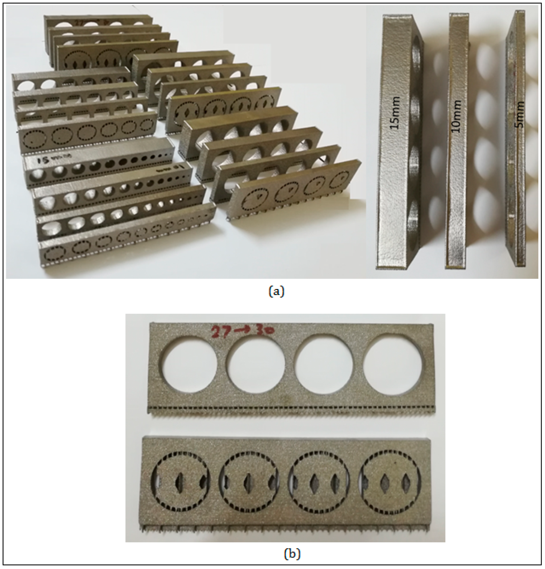
For the reason discussed earlier, it is crucial for the designer to diminish the utilization of support structures. Subsequently, the cylindricity, hardness, and microstructure were determined for holes with and without supports. It is important to mention here that the measured cylindricity error was not only produced from EBM process, but from the combination of the EBM process, support removal method, and operator intervention, etc. In order to cover a wide range of diameters, the overhanging round holes (without supports) with nominal diameters from 1 mm to 30 mm were fabricated by EBM. Each of these 30 holes was produced in three varying thicknesses of 5, 10, and 15 mm. The specimens with 30 different holes (nominal diameter) are shown in Figure 1. With regard to the analysis of the quality of holes as well as to determine events which result in the necessity for support structures, holes in the presence of supports were also fabricated. The automated generation of supports in most of the software takes place in the form of a block. The fabrication of this block structure consumes excess support material and involves inessential removal time. Therefore, a segmentation strategy has also been introduced to optimize the support structure. The experiment procedure can be summarized as follows.
- Fabrication of holes (without support structure) with nominal diameters from 1 mm to 30 mm in three different thicknesses (5, 10, and 15 mm).
- Measurement of cylindricity using the coordinate measuring machine (CMM).
- Fabrication of holes in the presence of the support structure.
- Manufacturing of holes using the optimized support structure.
- Evaluation of hardness and microstructure analysis for different holes.
The computer-aided design (CAD) models for the design were saved in stereolithography (STL) format and imported to Magics software (Ver. 18, Materialise NV, Leuven, Belgium) for orientation of holes in the horizontal direction as shown in Figure 2a. For holes with supports, all the test specimens were supported using a block support structure. Automated generation of the block support structure for the holes was carried out using a Magics software with default design parameters as shown in Figure 2b. The smallest round hole was supported by an automated block support structure of size 3 mm. Actually, no significant effect was observed when the bridge with thickness 4 mm was used in holes with diameters of 12, 13, 14, and 15 mm. This is because the deformation in the critical region had mainly occurred on initial layers and the designed height was sufficient to show any deformation. For holes without support, no support was applied to the overhang portion inside the holes as shown in Figure 2c. The support was applied only to anchor the whole part on the platform plate, which prevented the unnecessary movements of parts during the building process. Consequently, all the saved part models and supports in STL format were imported to Build Assembler software (ARCAM AB, Mölndal, Sweden). This software was used to convert the 3D-STL model in to thin cross sections (layers) and generated the beam path (ABF file).
The material used for fabricating the test specimens was Ti6Al4V. It was in powder form and possessed a chemical composition as shown in Table 1. The powder particle size was measured using laser diffraction technique (Mastersizer 2000, Malvern Instruments, Worcestershire, UK) and it was found that the powder particle size was distributed in a range between 53 and 107 µm, with a mean of around 75 µm (Figure 3).
The particle morphology was spherical or near-spherical, with some smaller particles adhering to the bigger ones. Figure 4 shows the microscopic investigation of Ti6Al4V powder.
ARCAM A2 machine (ARCAM AB, Mölndal, Sweden), which is based on the EBM process, was used to fabricate the test specimens. Figure 5 shows the schematic of EBM process and the corresponding set up. The principle of EBM process can be described as follows [46]: It involves a heated tungsten filament in a grid cup, which produces electrons in beam shape. The electrons are accelerated to the kinetic energy of about 60 keV and it produces a maximum power of 4.8 kW. There are three magnetic lenses in the drift tube, including an astigmatism lens and focus lens, and the deflection coils control the direction of the electron beam as shown in Figure 5. The astigmatism lens generates circular e-beam with a Gaussian energy distribution, while the focus lens focuses the beam to the required diameter and the deflection coil deflects the focused beam to the desired location (or scans the e-beam across the building area) [47]. There are two hoppers to hold the stock material and the rake is used to spread the powder over the build area. The build table moves down the Z-axis as the build progresses. In this process, the beam current is controlled in the range of 1–50 mA and each layer is first preheated by scanning the beam at low power and high velocity (104 mm/s) to sinter the particles. The melt scanning speed is reduced to 103 mm/s and the entire process takes place under a vacuum of 10−4 mbar in the chamber and 10−6 mbar in the gun. Once the melting and building up process is finished, fabricated parts are allowed to cool inside the chamber filled with helium gas.
The test parts were fabricated using the default preheating and melting parameters setting to minimize their influences. Individual layer thickness was set to 30 µm. As shown in Figure 6, the holes were built in X-Y axis and the hole overhang portion was supported by the sintered powder.
A stainless steel plate measuring 150 × 150 × 10 mm was chosen as the substrate plate upon which the parts were built (Figure 7a). Because of the preheating step during the building process, the unused powder inside and around each sample was also slightly sintered. The fabricated parts were removed from the EBM and the surrounding powder enveloped each sample. In order to remove the sintered powder, the fabricated parts were subjected to powder recovery system and blasted with compressed air of 6 bar. To improve the efficiency of the blasting process powder, the same material (Ti6Al4V) was fed along with the air stream (Figure 7b).
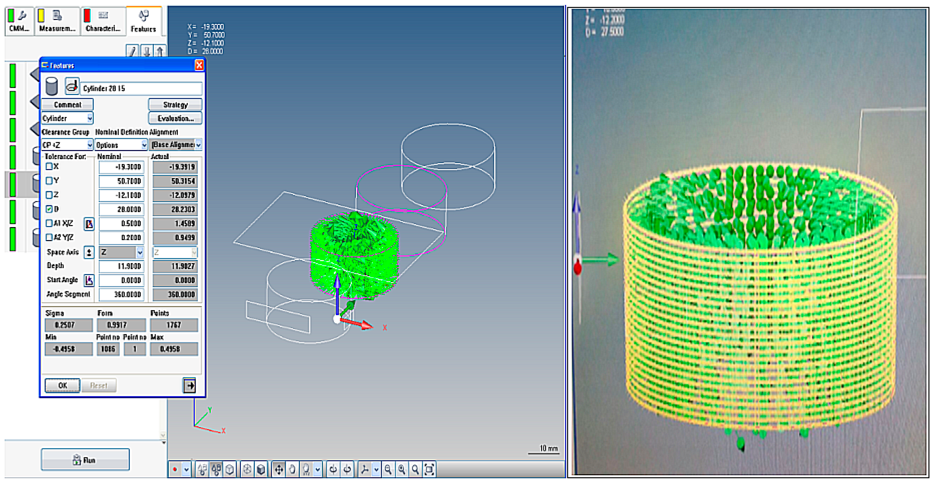
The investigation of fabricated specimens commenced with visual inspection, followed by measurement using CMM and finally, mechanical property and microstructure evaluation. To investigate the cylindricity of fabricated holes, CMM was utilized. A bridge-type CMM incorporated with a touch probe as shown in Figure 8 was used to evaluate the geometrical accuracy (cylindricity) of the fabricated holes. All the holes were measured three times, and then their averages were computed. To carry out the measurements, the parts were fixed on the CMM as shown in Figure 8. This fixture was simple and resulted in an immovable setup.
The measurement points distributed over 360° were utilized to compute the cylindricity of different holes. Figure 9 shows the measurement strategy adopted to compute the geometrical accuracy of various holes.
To measure the cylindricity, a minimum of two levels and six points (three points in each level) are sufficient. However, in the present study, a large number of points that could cover the entire measurement surface were considered. The measurement strategy was decided depending on the hole diameter as well as its thickness. The number of levels increased with increase in thickness, while the number of points in each level increased with the increase in the hole diameter. The number of levels were kept at 5, 15, and 25 for thicknesses of 5, 10, and 15 mm, respectively. Additionally, the distance between points in each level was maintained at 0.1 mm. For example, the hole with diameter 10 mm and thickness 5 mm had a total of 500 measurement points as compared to the hole of diameter 24 mm and thickness 10 mm, which had a total of 3600 points.
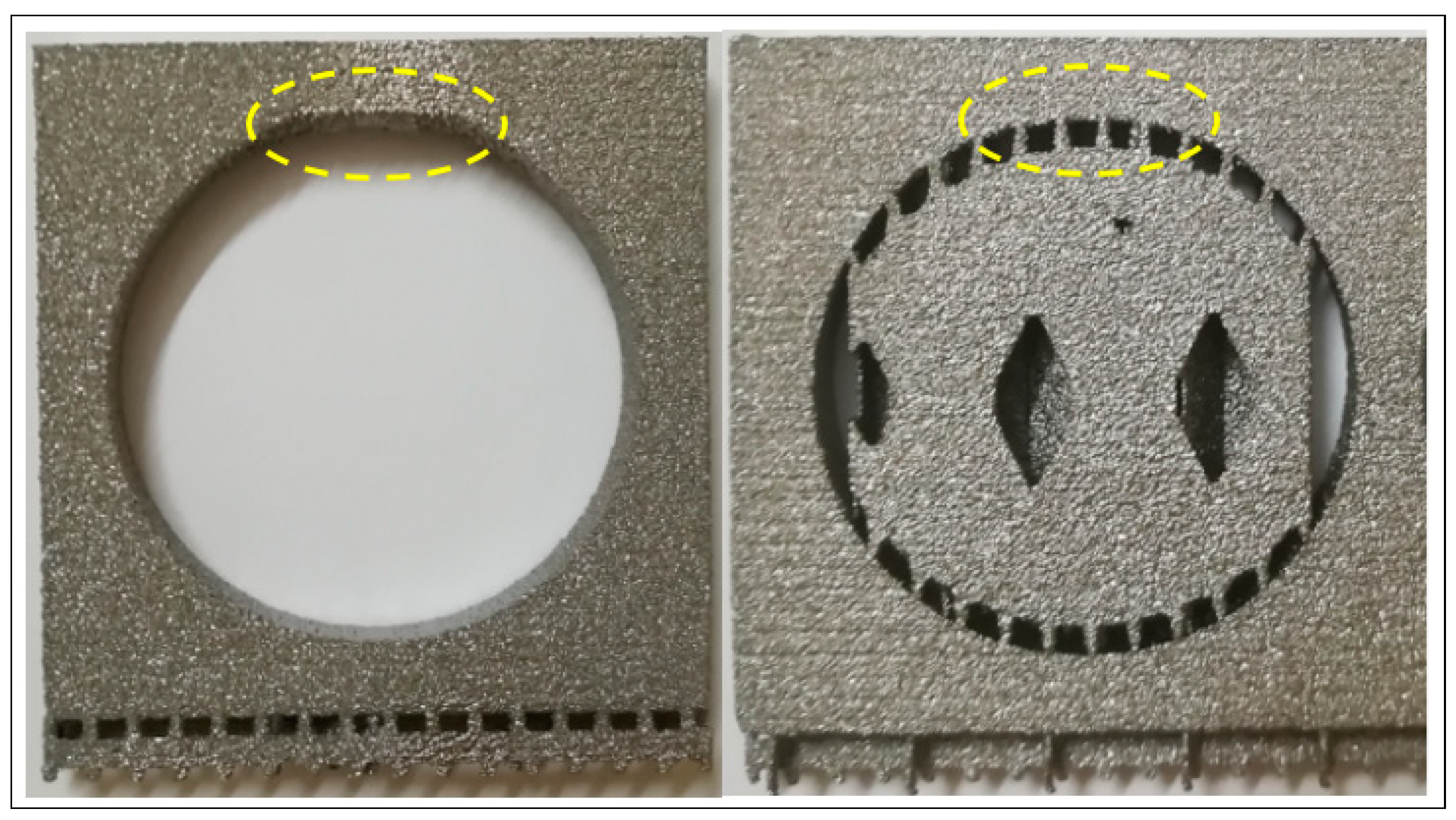
With reference to the size of the support structure, it was found that the default support structure filled the entire hole as shown in Figure 10a, thus resulting in higher building time and higher support removal time as well as wastage of material and higher cost of the final part. It suggested that there should be a trade-off between geometric accuracy, building time, support removal time, and post-processing. An approach which could minimize the size of support while maintaining the geometric accuracy of the overhang holes was essential. Therefore, a segmentation strategy was adopted to design the support structures for different holes.
The developed segmentation strategy classified the hole overhang surface into critical and non-critical regions. An overhanging region was considered as critical (X as shown in Figure 10b) if sufficient heat dissipation was not possible; else, it was called a non-critical region. The non-critical region was surrounded with a significant amount of solid material, which could adequately dissipate heat, thus preventing geometrical distortion.
The mechanical properties play an important role in actual applications. However, in the present study it was difficult to carry out tensile test because of the smaller size of the critical regions. Therefore, a Vicker’s micro-hardness test was performed to estimate the residual yield strength. The relationship between the yield strength and Vicker’s micro-hardness values is σy ≈ HV/3 [8,48]. The indenter machine used was a ZHVµ Micro Vickers hardness tester (Zwick/Roell, Ulm, Germany). The parameters used for the tests were 500 gf (force) and 10 s (dwell time).
To check the influence of the support structure on the mechanical properties of overhangs, a micro-hardness test was performed near to the overhanging portion of the produced samples. The micro hardness test was done on the front face near the edge of the holes, not on the top face where the support structures were applied. Prior to the tests, the surfaces of the test specimens were ground and polished using sand paper (30–1200 grit).
The Vickers micro-hardness tester was used for the hardness measurements at five locations. Additionally, the variation in microstructure of hole (with large diameter) with and without support as well as with critical support was also analyzed using a scanning electron microscope (SEM).
4. Results and Discussion
In addition to numerous benefits, the deployment of support structures brings post-processing steps, which in turn increases cost and time. Therefore, it is crucial to minimize the use of support structures, especially in the case of critical features or at inaccessible locations in the part. Moreover, unnecessary support structures within critical features may also lead to undesirable characteristics in parts, thus reducing the benefits of using EBM process. Hence, the specifications for limiting support structures are important in fabricating the overhanging features by the AM process. In view of the above-mentioned objectives, a significant number of specimens were fabricated. The fabricated test specimens after blasting process can be realized in Figure 11.
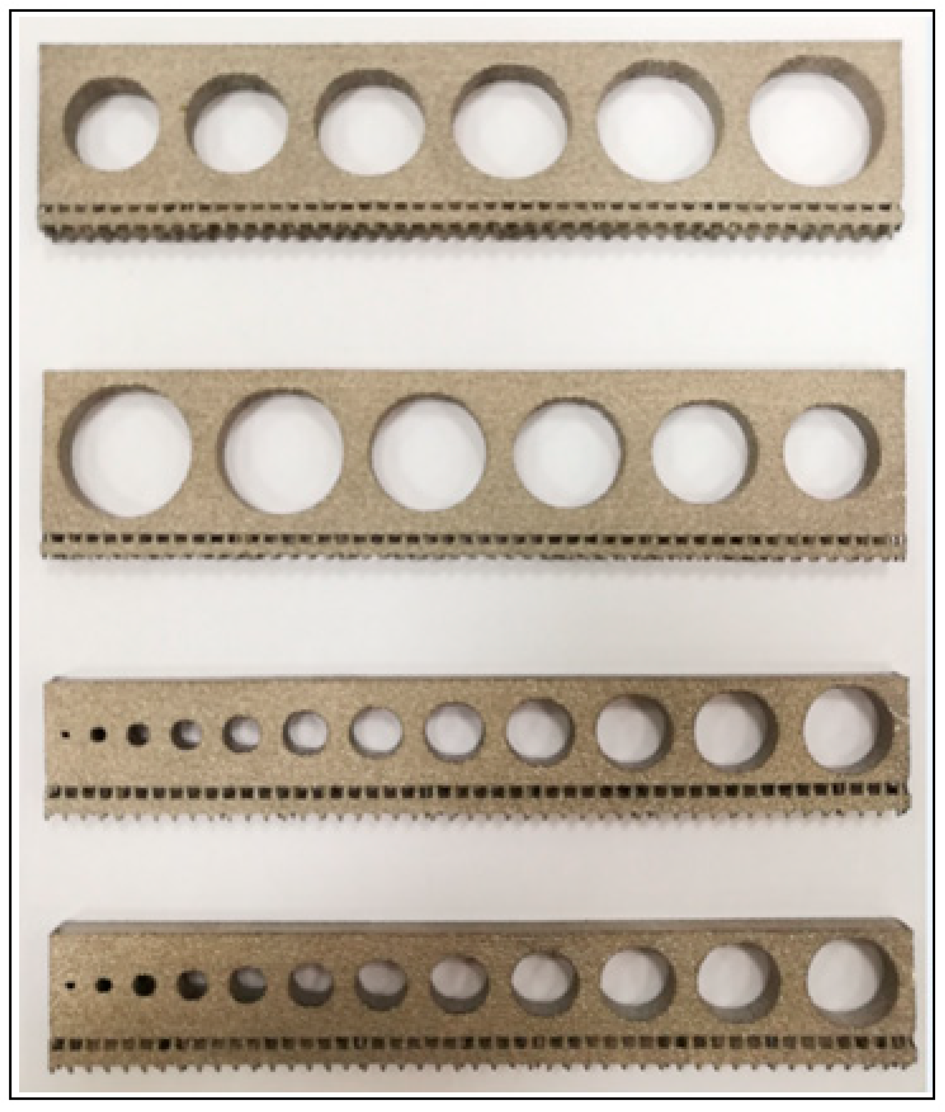
Foremost, all the fabricated specimens were examined through visual inspection. This initial observation confirmed EBM’s capability to fabricate overhang round holes without support structure successfully. All the holes with varying diameters and thicknesses were produced successfully without any major defects as shown in Figure 12. In fact, it was impractical to point out any distortion visually; therefore, further examination was carried out.
A more thorough investigation disclosed a sagging phenomenon, especially in case of larger holes (diameter ≥ 18 mm), as shown in Figure 13. Because of this sagging effect (or formed deposited material), the roughness on the top portions of the holes was significant. Certainly, this effect increased with the increase in the hole diameter as well as its thickness. This sagging effect also influenced the cylindricity of the fabricated holes. The sagging effect was pronounced in holes without support as compared to holes with support structure, where the effect was minimal as shown in Figure 13. In case of holes without support, the intense power of the electron beam penetrating through the unmelted powder at greater depth must have caused this defect. However, the presence of support structure (dense metal) beneath the layer being melted (in holes with supports) must have conducted all the heat away from the concerned feature, thus preventing any sagging.
Upon further analysis as shown in Figure 14, it was identified that cylindricity deteriorated with the increase in the hole diameter as well as the thickness. It suggested that the cylindricity of holes decreased with increase in the hole diameter. Indeed, it was striking to note that the cylindricity of hole was satisfactory (in the range of 200 µm) until hole diameter reached 18 mm in 5-mm-thick samples. This means that overhanging holes can be accurately fabricated (within 200 µm) by EBM without support until reaching an 18-mm diameter with 5-mm thickness. This represents a threshold value for producing overhanging holes without the need for support in EBM. It was also observed that the cylindricity declined with increase in the thickness and in fact, in the case of larger thicknesses, the cylindricity decreased remarkably with the increase in the hole diameter.
Consequently, the comparison of holes with and without support for the thickness of 5 mm was carried out in order to examine the influence of the support structure. As shown in Figure 15, it was revealed that the presence of a support structure had actually degraded the cylindricity in holes with diameter less than 20 mm. The results have also shown that the addition of a support structure enhanced the geometric accuracy of holes with diameter greater than 20 mm. This observation provides evidence for the use of support structures in holes with diameter greater than 20 mm.
The support removal time was also recorded and analyzed (shown in Figure 16) in order to emphasize the importance of minimizing the usage of support structure. The supports had to be removed using the plier and a small pin punch. From the analysis, it was obvious that support removal in smaller holes (less than 8 mm in size) and larger holes (diameter greater than 20 mm) consumed comparatively higher time as compared to the other holes. The smaller holes due to their small size and larger holes with higher contact area with the support complicated the process of support removal.
The application of the support structure also increases the overall cost of the EBM production, and therefore its usage must be checked. It was apparent that the cost of production would increase with the increase in the volume of the support structure. As shown in Figure 17, the volume of the support structure increased with the increase in the hole diameter and the part thickness. Therefore, a strategy that can optimize the volume of the support would be beneficial to minimize the support removal time as well as the costs of production.
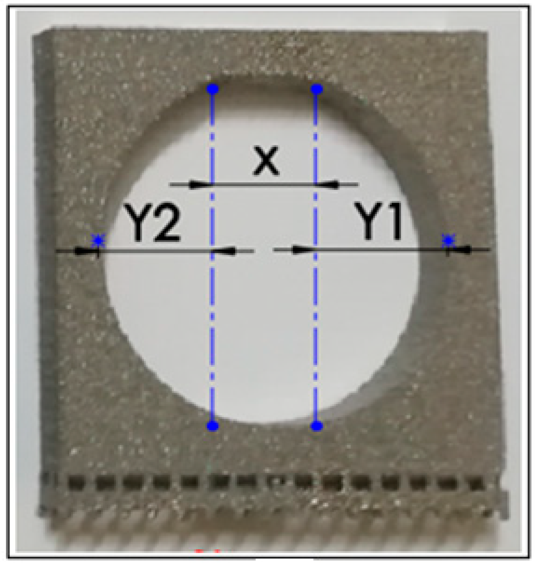
Based on visual inspection and digital vernier measurements, it was confirmed that the deformation occurred in a small region at the inside top of the hole (X) (i.e., around one-third of hole diameter) and the remaining whole surface was self-supporting (Y1 and Y2) as shown in Figure 18.
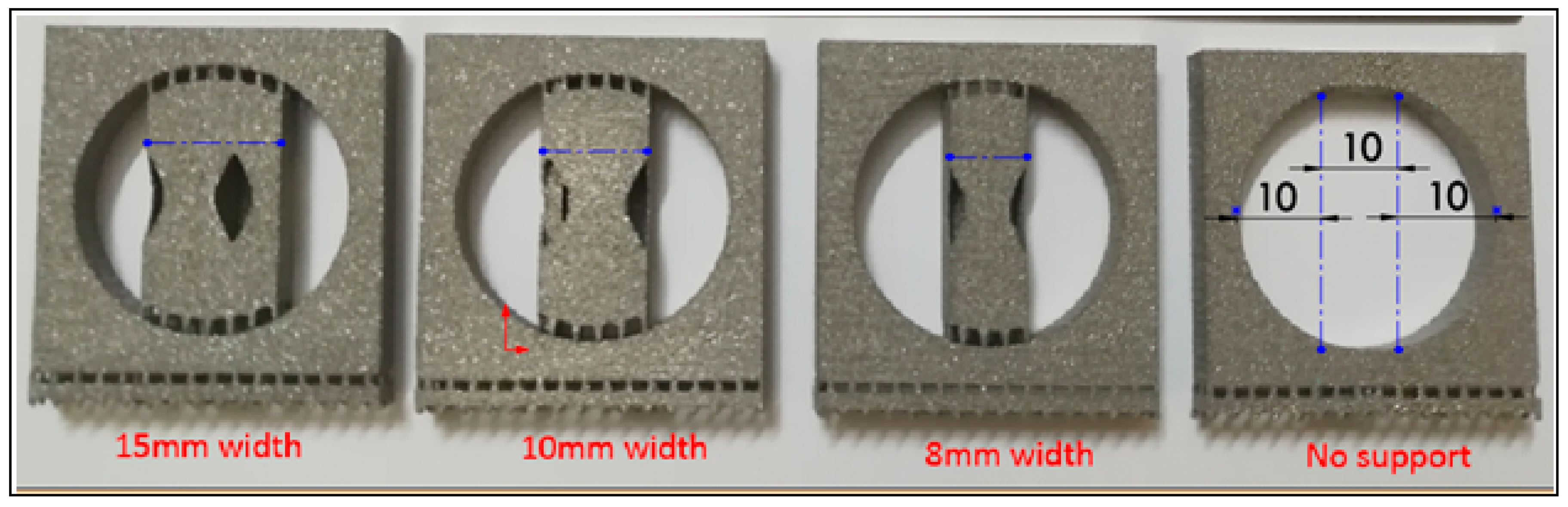
Therefore, the segmentation strategy was implemented and the hole specimens (with diameters of 30 mm) with different segmentation levels of support structures were fabricated as shown in Figure 19. The visual inspection and CMM measurement confirmed that the assigned support structure with a 10-mm width (which is one-third of the diameter) provided the finest balance between geometric accuracy, amount of material used, building time, and post-processing time.
Figure 20 shows the micro-hardness comparison of 30-mm-diameter and 5-mm-thick samples built with support, without support, and with 10-mm support at the critical area. It was observed that the micro-hardness of the sample built without support was significantly lower than the sample that was built with support. However, the addition of 10-mm-width support at the critical region resulted in a slight increase in the hardness.
Figure 21 shows the hardness results for 17-mm-diameter samples built with supports and without supports. It was observed that the hardness of overhang without support was lower than that of the overhang with support. However, the hardness values were similar to those of the base metal, suggesting that the absence of support structure for 17-mm-diameter overhang did not have a significant influence on the hardness.
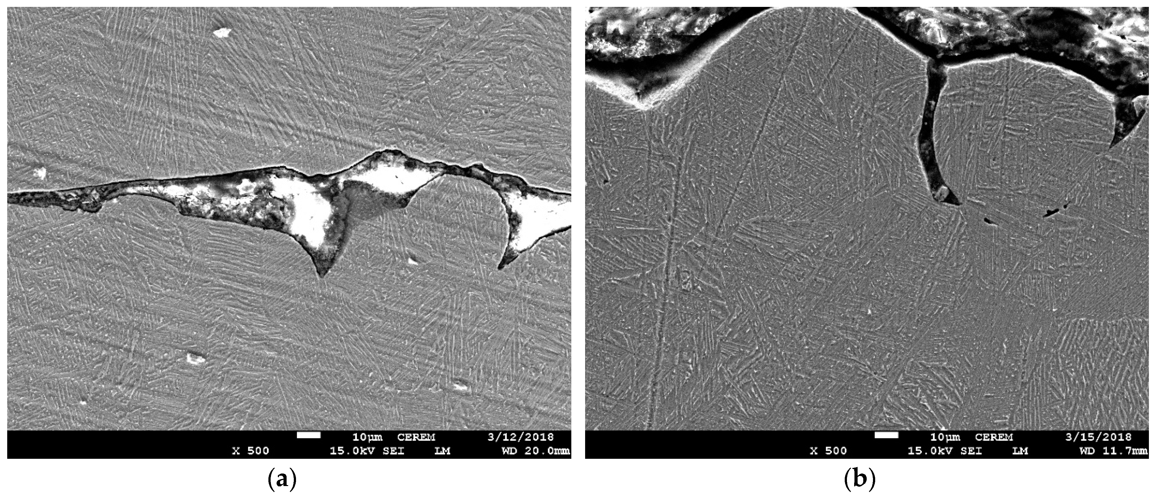
Optical microscopy of the 30-mm-diameter and 5-mm-thick samples built with support and without support revealed similar microstructures with approximately the same grain size. However, the α lathe thickness was little greater in the sample built without support, as can be seen in Figure 22b. This increased α lathe thickness resulted in the small decrease in hardness.
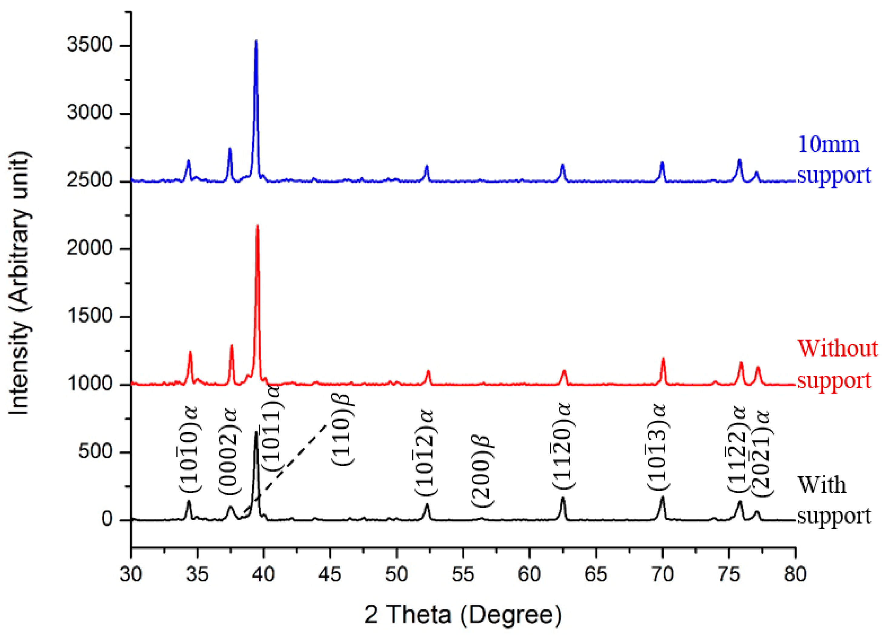
In order to see the effect of support structure on the phases, X-ray Powder Diffraction (XRD) patterns (Figure 23) were obtained for the samples built with support, without support, and with 10-mm support. A similar pattern was observed for all the samples with most peaks relating to the α phase and a few peaks of the β phase.
The microstructure of the electron beam-melted Ti6Al4V alloy consists of an α + β phase with both an α colony and Widmanstätten morphology. The retained β phase appeared as rods and dots embedded within the α region, as shown in Figure 24a. Figure 24 shows the SEM images of 30-mm-diameter and 5-mm-thick cylindrical overhangs with support, without support, and with 10-mm critical support. In the present work, no significant variation in the microstructure was observed for the samples built with and without support. Moreover, in the defects associated with AM such as the unmelted powder particles, gas-entrapped micro voids were present in all samples and the absence of a support structure did not further increase these defects. However, the 10-mm critical support sample shown in Figure 24d had minimal defects as compared to the other two samples.
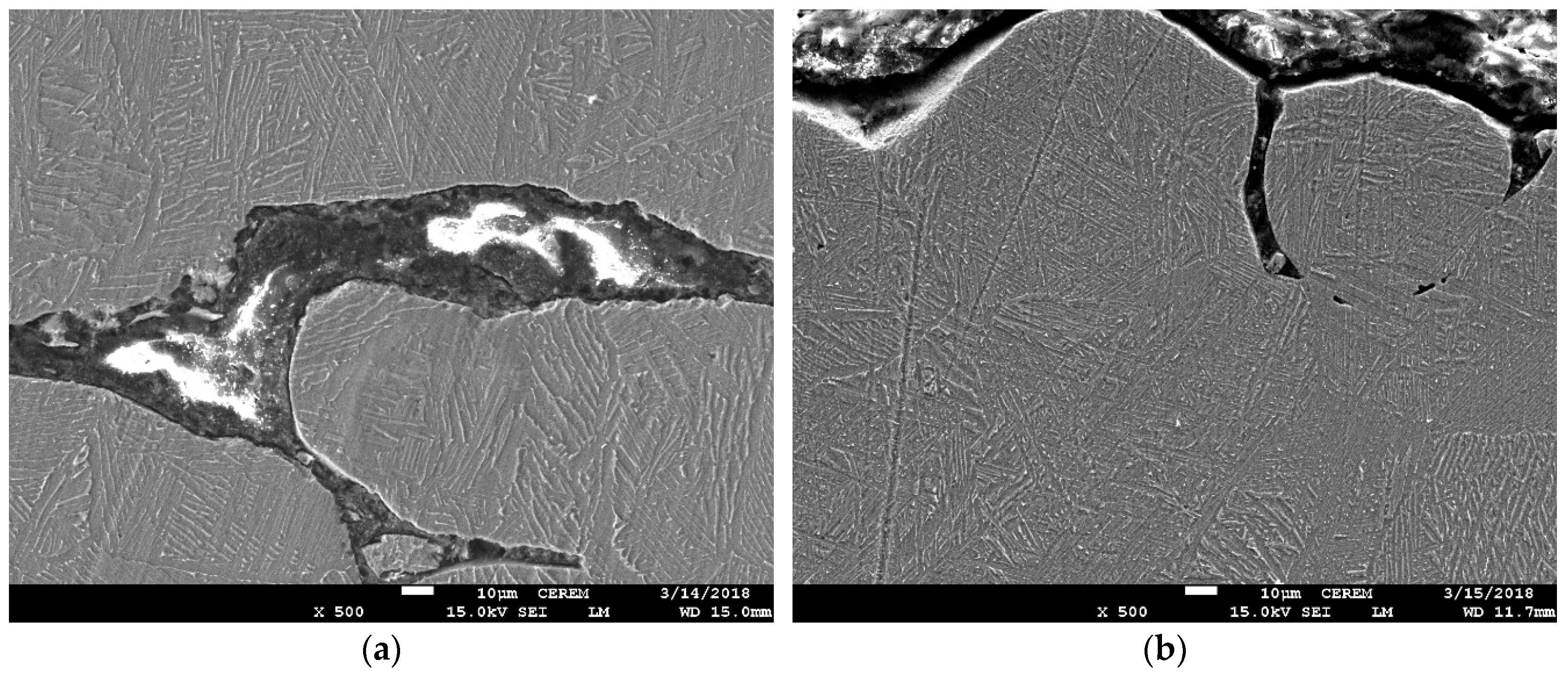
Figure 25 shows the SEM images of 17-mm-diameter and 5-mm-thick cylindrical overhangs with and without support. Both the samples showed similar defects and that the absence of support did not further increase the defects. In addition, there was no significant variation in the microstructure of the sample built without a support structure.
Figure 26 shows the SEM images of 5-mm and 15-mm-thick cylindrical samples with 30-mm diameters built without support. The β phase seems to be little thick in the 15-mm-thick overhang samples as compared to the 5-mm-thick sample.
Figure 27 shows the SEM images of the 17-mm-diameter and 30-mm-diameter cylindrical samples built without support. The 17-mm-diameter cylindrical sample was better than the 30-mm-diameter sample in terms of the defects. In addition, there was no variation in the microstructure.
5. Conclusions
The objective of this work was the minimization of the use of the support structure in overhang round holes. An experimental approach was adopted to investigate the manufacturability of round holes with and without support. A significant number of overhang holes with and without support structures were manufactured using EBM, and a segmentation strategy was introduced to optimize the application of the support structure. Subsequently, this work extensively examined the EBM-fabricated overhanging round holes and identified the limit or threshold of self-support. Based on above analysis, the following conclusions can be drawn:
- A sagging effect (or formed deposited material) was notably observed in large holes (diameter ≥ 18 mm). This effect increased with the increase in the hole diameter as well as its thickness and it also influenced the cylindricity of the fabricated holes.
- The sagging phenomenon was noticeable in holes without support, in contrast to holes with a support structure where the effect was the lowest.
- The cylindricity of overhang round holes decreased with the increase in the hole diameter as well as the thickness.
- The cylindricity of holes was within the range of 200 µm until the hole diameter reached 18 mm in 5-mm-thick samples. This defines the threshold value for constructing the overhang holes without support in EBM.
- With increases in the hole thickness, the cylindricity decreased significantly with the increase in the hole diameter.
- The analysis and the implementation of a segmentation strategy established that the support structure with a 10-mm width (which is one-third of the diameter) provided the perfect balance between geometric accuracy, amount of material used, building time, and post-processing time.
- It was revealed that the micro-hardness of the sample built without support was significantly lower than in the sample that was built with support.
- For the overhang holes with a 17-mm diameter, the hardness of samples fabricated without support was lower than in the samples produced with support, but was similar to that of the base metal. This suggests that the absence of a support structure for 17-mm-diameter overhang holes did not have a significant influence on the hardness.
- No significant variation in the microstructure was observed for the samples built with and without support. This means that the absence of support did not further increase the defects.
- The comparison of 17-mm-diameter and 30-mm-diameter cylindrical samples built without support revealed that the 17-mm-diameter holes were better than the 30-mm-diameter holes in terms of the defects. However, there was no variation in the microstructure.
Author Contributions
W.A. and A.A.-A. conceived and designed the study. W.A. and M.K.M. conducted the EBM experiments. W.A., S.H.M. and M.K.M. conducted the measurements and analyzed the results. W.A. and S.H.M. wrote the manuscript. W.A., S.H.M. and M.K.M reviewed the manuscript. A.A.-A. supervised the work.
Acknowledgments
The authors are grateful to the Deanship of Scientific Research, King Saud University for funding through the Vice Deanship of Scientific Research Chairs.
Conflicts of Interest
The authors declare no conflict of interest.
References
- Standard Terminology for Additive Manufacturing Technologies; ASTM F2792-12a; ASTM International: West Conshohocken, PA, USA, 2012.
- Beiker Kair, A.; Sofos, K. Additive Manufacturing and Production of Metallic Parts in Automotive Industry: A Case Study on Technical, Economic and Environmental Sustainability Aspects. 2014. Available online: http://www.diva-portal.org/smash/record.jsf?pid=diva2%3A740682&dswid=-4901 (accessed on 26 August 2014).
- Guo, N.; Leu, M.C. Additive manufacturing: Technology, applications and research needs. Front. Mech. Eng. 2013, 8, 215–243. [Google Scholar] [CrossRef]
- Gibson, I.; Rosen, D.W.; Stucker, B. Additive Manufacturing Technologies; Springer: Berlin, Germany, 2010; Volume 238. [Google Scholar]
- Frazier, W.E. Metal additive manufacturing: A review. J. Mater. Eng. Perform. 2014, 23, 1917–1928. [Google Scholar] [CrossRef]
- Murr, L.E.; Quinones, S.A.; Gaytan, S.M.; Lopez, M.I.; Rodela, A.; Martinez, E.Y.; Hernandez, D.H.; Martinez, E.; Medina, F.; Wicker, R.B. Microstructure and mechanical behavior of Ti–6Al–4V produced by rapid-layer manufacturing, for biomedical applications. J. Mech. Behav. Biomed. Mater. 2009, 2, 20–32. [Google Scholar] [CrossRef] [PubMed]
- Liska, W.D.; Marcellin-Little, D.J.; Eskelinen, E.V.; Sidebotham, C.G.; Harrysson, O.L.; Hielm-Björkman, A.K. Custom total knee replacement in a dog with femoral condylar bone loss. Vet. Surg. 2007, 36, 293–301. [Google Scholar] [CrossRef] [PubMed]
- Murr, L.E.; Gaytan, S.M.; Ceylan, A.; Martinez, E.; Martinez, J.L.; Hernandez, D.H.; Machado, B.I.; Ramirez, D.A.; Medina, F.; Collins, S.; et al. Characterization of titanium aluminide alloy components fabricated by additive manufacturing using electron beam melting. Acta Mater. 2010, 58, 1887–1894. [Google Scholar] [CrossRef]
- Cheng, B.; Chou, Y.K. Overhang Support Structure Design for Electron Beam Additive Manufacturing. In Proceedings of the ASME 2017 12th International Manufacturing Science and Engineering Conference Collocated with the JSME/ASME 2017 6th International Conference on Materials and Processing, Los Angeles, CA, USA, 4–8 June 2017; American Society of Mechanical Engineers: New York, NY, USA, 2017. [Google Scholar]
- Calignano, F. Design optimization of supports for overhanging structures in aluminum and titanium alloys by selective laser melting. Mater. Des. 2014, 64, 203–213. [Google Scholar] [CrossRef]
- Poyraz, Ö.; Yasa, E.; Akbulut, G.; Orhangül, A.; Pilatin, S. Investigation of Support Structures for Direct Metal Laser Sintering (Dmls) of In625 Parts. In Proceedings of the International Solid Freeform Fabrication Symposium, Austin, TX, USA, 7–9 August 2015. [Google Scholar]
- Gan, M.; Wong, C. Practical support structures for selective laser melting. J. Mater. Process. Technol. 2016, 238, 474–484. [Google Scholar] [CrossRef]
- Hussein, A.; Yan, C.; Everson, R.; Hao, L. Preliminary investigation on cellular support structures using SLM process. In Innovative Developments in Virtual and Physical Prototyping; Taylor & Francis Group: London, UK, 2011; pp. 609–612. [Google Scholar]
- Zeng, K. Optimization of support structures for selective laser melting. In Industrial Engineering; University of Louisville: Louisville, KY, USA, 2015. [Google Scholar]
- Calignano, F.; Manfred, D. Production of overhanging structures by DMLS. In High Value Manufacturing: Advanced Research in Virtual and Rapid Prototyping, Proceedings of the 6th International Conference on Advanced Research in Virtual and Rapid Prototyping, Leiria, Portugal, 1–5 October 2013; CRC Press: Boca Raton, FL, USA, 2013. [Google Scholar]
- Ramitounsi; Frederic, V. New concept of support structures in Electron Beam Melting manufacturing to reduce geomtricdefects. In Proceedings of the 15e Colloque National AIP-Priméca, La Plagne, France, 12–14 April 2017. [Google Scholar]
- Thomas, D. The Development of Design Rules for Selective Laser Melting. Ph.D. Thesis, University of Wales, Cardiff, UK, 2009. [Google Scholar]
- Cheng, B.; Chou, K. Deformation Evaluation of Part Overhang Configurations in Electron Beam Additive Manufacturing. In Proceedings of the ASME 2015 International Manufacturing Science and Engineering Conference, Charlotte, NC, USA, 8–12 June 2015; American Society of Mechanical Engineers: New York, NY, USA, 8–12 June 2015. [Google Scholar]
- Vora, P.; Derguti, F.; Mumtaz, K.; Todd, I.; Hopkinson, N. Investigating a Semi-Solid Processing Technique Using Metal Powder Bed Additive Manufacturing Processes. In Proceedings of the 24th Annual International Solid Freeform Fabrication Symposium—An Additive Manufacturing Conference, Austin, TX, USA, 12–14 August 2013. [Google Scholar]
- Cheng, B.; Lu, P.; Chou, K. Thermomechanical Investigation of Overhang Fabrications In Electron Beam Additive Manufacturing. In Proceedings of the ASME 2014 International Manufacturing Science and Engineering Conference Collocated with the JSME 2014 International Conference on Materials and Processing and the 42nd North American Manufacturing Research Conference, Detroit, MI, USA, 9–13 June 2014; American Society of Mechanical Engineers: New York, NY, USA, 9–13 June 2014. [Google Scholar]
- Järvinen, J.-P.; Matilainen, V.; Li, X.; Piili, H.; Salminen, A.; Mäkelä, I.; Nyrhilä, O. Characterization of effect of support structures in laser additive manufacturing of stainless steel. Phys. Procedia 2014, 56, 72–81. [Google Scholar] [CrossRef]
- Wang, D.; Yang, Y.; Zhang, M.; Lu, J.; Liu, R.; Xiao, D. Study on SLM fabrication of precision metal parts with overhanging structures. In Proceedings of the IEEE 2013 IEEE International Symposium on Assembly and Manufacturing (ISAM), Xi’an, China, 30 July–2 August 2013. [Google Scholar]
- Wang, D.; Mai, S.; Xiao, D.; Yang, Y. Surface quality of the curved overhanging structure manufactured from 316-L stainless steel by SLM. Int. J. Adv. Manuf. Technol. 2016, 86, 781–792. [Google Scholar] [CrossRef]
- Cheng, B.; Chou, K. Geometric consideration of support structures in part overhang fabrications by electron beam additive manufacturing. Comput. -Aided Des. 2015, 69, 102–111. [Google Scholar] [CrossRef]
- Allen, S.; Dutta, D. On the computation of part orientation using support structures in layered manufacturing. In Proceedings of the Solid Freeform Fabrication Symposium, Austin, TX, USA, June 1994. DTIC Document. [Google Scholar]
- Leary, M.; Merli, L.; Torti, F.; Mazur, M.; Brandt, M. Optimal topology for additive manufacture: A method for enabling additive manufacture of support-free optimal structures. Mater. Des. 2014, 63, 678–690. [Google Scholar] [CrossRef]
- Li, Z.; Zhang, D.; Dong, P.; Kucukkoc, I. A lightweight and support-free design method for selective laser melting. Int. J. Adv. Manuf. Technol. 2017, 90, 2943–2953. [Google Scholar] [CrossRef]
- Langelaar, M. Topology optimization of 3D self-supporting structures for additive manufacturing. Addit. Manuf. 2016, 12, 60–70. [Google Scholar] [CrossRef]
- Yan, C.; Hao, L.; Hussein, A.; Raymont, D. Evaluations of cellular lattice structures manufactured using selective laser melting. Int. J. Mach. Tools Manuf. 2012, 62, 32–38. [Google Scholar] [CrossRef]
- Atzeni, E.; Salmi, A. Study on unsupported overhangs of alsi10mg parts processed by direct metal laser sintering (dmls). J. Manuf. Process. 2015, 20, 500–506. [Google Scholar] [CrossRef]
- Gaynor, A.T.; Guest, J.K. Topology optimization considering overhang constraints: Eliminating sacrificial support material in additive manufacturing through design. Struct. Multidiscip. Optim. 2016, 54, 1157–1172. [Google Scholar] [CrossRef]
- Meisel, N.; Williams, C. An investigation of key design for additive manufacturing constraints in multimaterial three-dimensional printing. J. Mech. Des. 2015, 137, 111406. [Google Scholar] [CrossRef]
- Vayre, B.; Vignat, F.; Villeneuve, F. Identification on some design key parameters for additive manufacturing: Application on electron beam melting. Procedia CIRP 2013, 7, 264–269. [Google Scholar] [CrossRef]
- Vora, P.; Mumtaz, K.; Todd, I.; Hopkinson, N. AlSi12 in-situ alloy formation and residual stress reduction using anchorless selective laser melting. Addit. Manuf. 2015, 7, 12–19. [Google Scholar] [CrossRef]
- Cheng, B.; Chou, K. Thermal Stresses Associated with Part Overhang Geometry in Electron Beam Additive Manufacturing: Process Parameter Effects. In Proceedings of the 25th Annual International Solid Freeform Fabrication Symposium—An Additive Manufacturing Conference, Austin, TX, USA, 9–11 August 2014. [Google Scholar]
- Chou, Y.-S.; Cooper, K. Systems and Methods for Designing and Fabricating Contact-Free Support Structures for Overhang Geometries of Parts in Powder-Bed Metal Additive Manufacturing. U.S. Patent 14276345, 13 May 2014. [Google Scholar]
- Canellidis, V.; Giannatsis, J.; Dedoussis, V. Genetic-algorithm-based multi-objective optimization of the build orientation in stereolithography. Int. J. Adv. Manuf. Technol. 2009, 45, 714–730. [Google Scholar] [CrossRef]
- Lan, P.-T.; Chou, S.-Y.; Chen, L.-L.; Gemmill, D. Determining fabrication orientations for rapid prototyping with stereolithography apparatus. Comput.-Aided Des. 1997, 29, 53–62. [Google Scholar]
- Hu, K.; Zhang, X.; Wang, C.C. Direct computation of minimal rotation for support slimming. In Proceedings of the 2015 IEEE International Conference on Automation Science and Engineering (CASE), Gothenburg, Sweden, 24–28 August 2015. [Google Scholar]
- Ezair, B.; Massarwi, F.; Elber, G. Orientation analysis of 3D objects toward minimal support volume in 3D-printing. Comput. Graph. 2015, 51, 117–124. [Google Scholar] [CrossRef]
- Hu, K.; Jin, S.; Wang, C.C. Support slimming for single material based additive manufacturing. Comput.-Aided Des. 2015, 65, 1–10. [Google Scholar] [CrossRef]
- Mumtaz, K.; Vora, P.; Hopkinson, N. A method to eliminate anchors/supports from directly laser melted metal powder bed processes. In Proceedings of the Solid Freeform Fabrication Symposium, Austin, TX, USA, 6–8 August 2011. [Google Scholar]
- Wu, C.; Dai, C.; Fang, G.; Liu, Y.-J.; Wang, C. RoboFDM: A robotic system for support-free fabrication using FDM. In Proceedings of the 2017 IEEE International Conference on Robotics and Automation (ICRA), Singapore, 29 May–3 June 2017. [Google Scholar]
- Guo, X.; Zhou, J.; Zhang, W.; Du, Z.; Liu, C.; Liu, Y. Self-supporting structure design in additive manufacturing through explicit topology optimization. Comput. Methods Appl. Mech. Eng. 2017, 323, 27–63. [Google Scholar] [CrossRef]
- Dunbar, A.J. Analysis of the Laser Powder Bed Fusion Additive Manufacturing Process through Experimental Measurement and Finite Element Modeling. Ph.D. Thesis, The Pennsylvania State University, University Park, PA, USA, 1 March 2016. [Google Scholar]
- Koike, M.; Martinez, K.; Guo, L.; Chahine, G.; Kovacevi, R.; Okabe, T. Evaluation of titanium alloy fabricated using electron beam melting system for dental applications. J. Mater. Process. Technol. 2011, 211, 1400–1408. [Google Scholar] [CrossRef]
- Karlsson, J. Optimization of Electron Beam Melting for Production of Small Components in Biocompatible Titanium Grades; Acta Universitatis Upsaliensis: Uppsala, Sweden, 2015. [Google Scholar]
- Mohammad, A.; Al-Ahmari, A.; Alfaify, A.; Mohammed, M.K. Effect of melt parameters on density and surface roughness in electron beam melting of gamma titanium aluminide alloy. Rapid Prototyp. J. 2017, 23, 474–485. [Google Scholar] [CrossRef]
Figure 1.
Design of the round overhang holes.
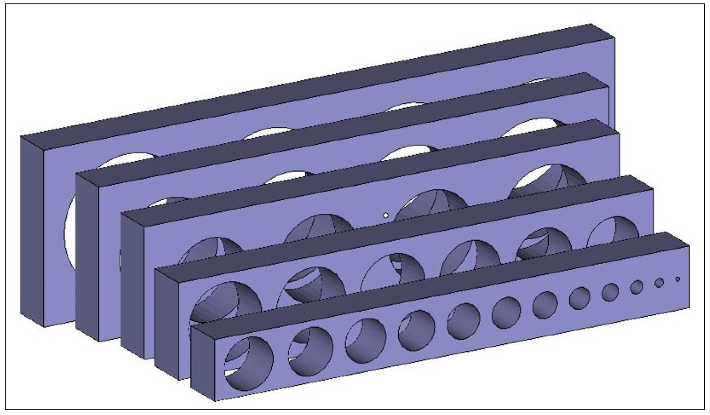
Figure 2.
(a) Oriented hole model; (b) Holes with automated support structures; (c) Holes without support structures.
Figure 2.
(a) Oriented hole model; (b) Holes with automated support structures; (c) Holes without support structures.
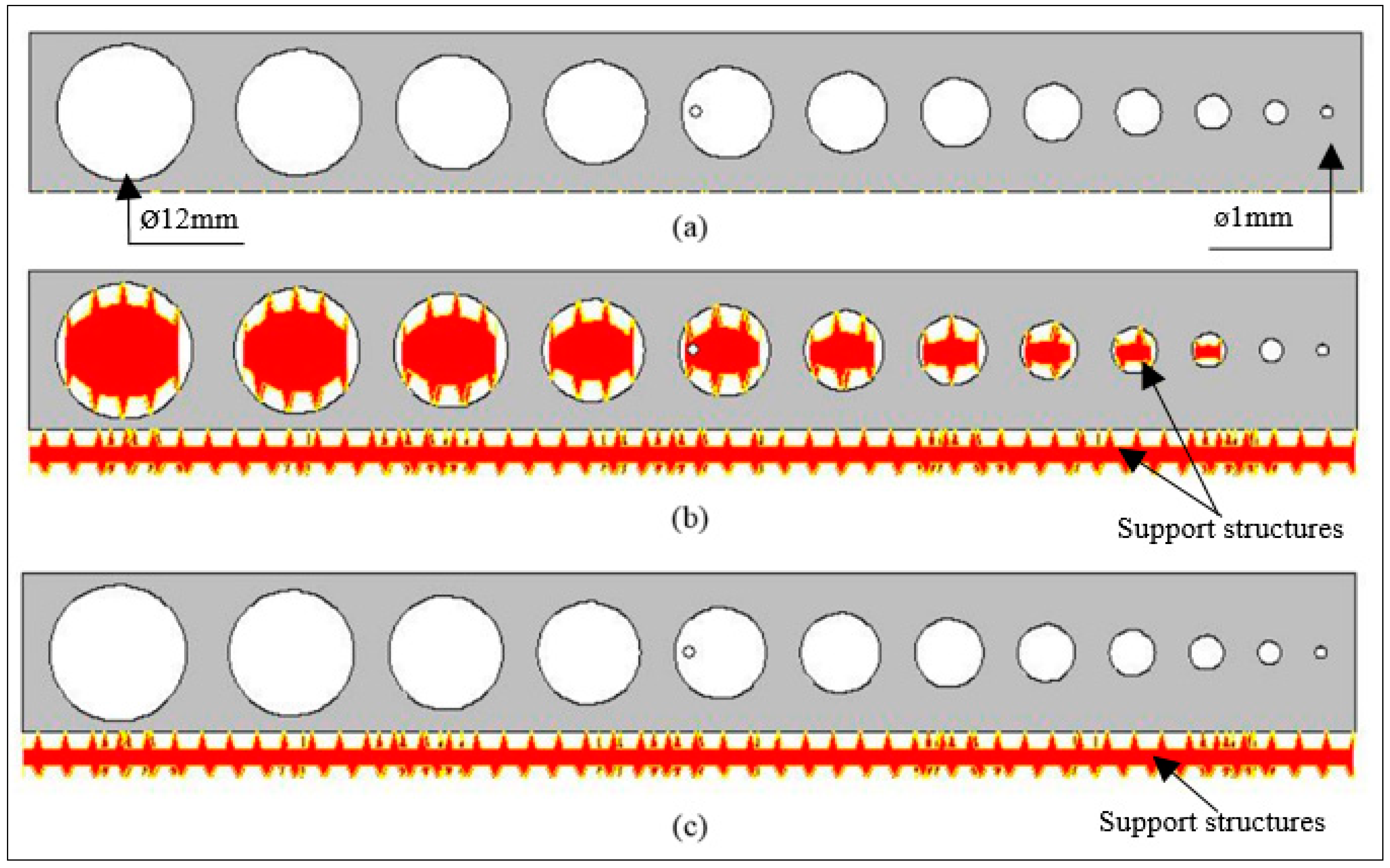
Figure 3.
Measured powder particle size distribution.

Figure 4.
Scanning electron microscope image of Ti6Al4V powder particles.

Figure 5.
(a) Schematic of electron beam melting (EBM); (b) ARCAM machine used in this study.

Figure 6.
Building of hole by EBM.
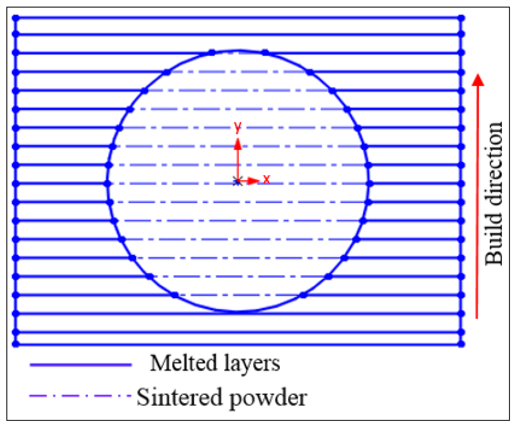
Figure 7.
(a) The build with sintered powder; (b) Powder recovery system.

Figure 8.
The coordinate measuring machine (CMM) measurement system.

Figure 9.
Measuring strategy adopted to compute the cylindricity.

Figure 10.
(a) Default support structures of round holes; (b) Critical and non-critical overhang regions.
Figure 10.
(a) Default support structures of round holes; (b) Critical and non-critical overhang regions.
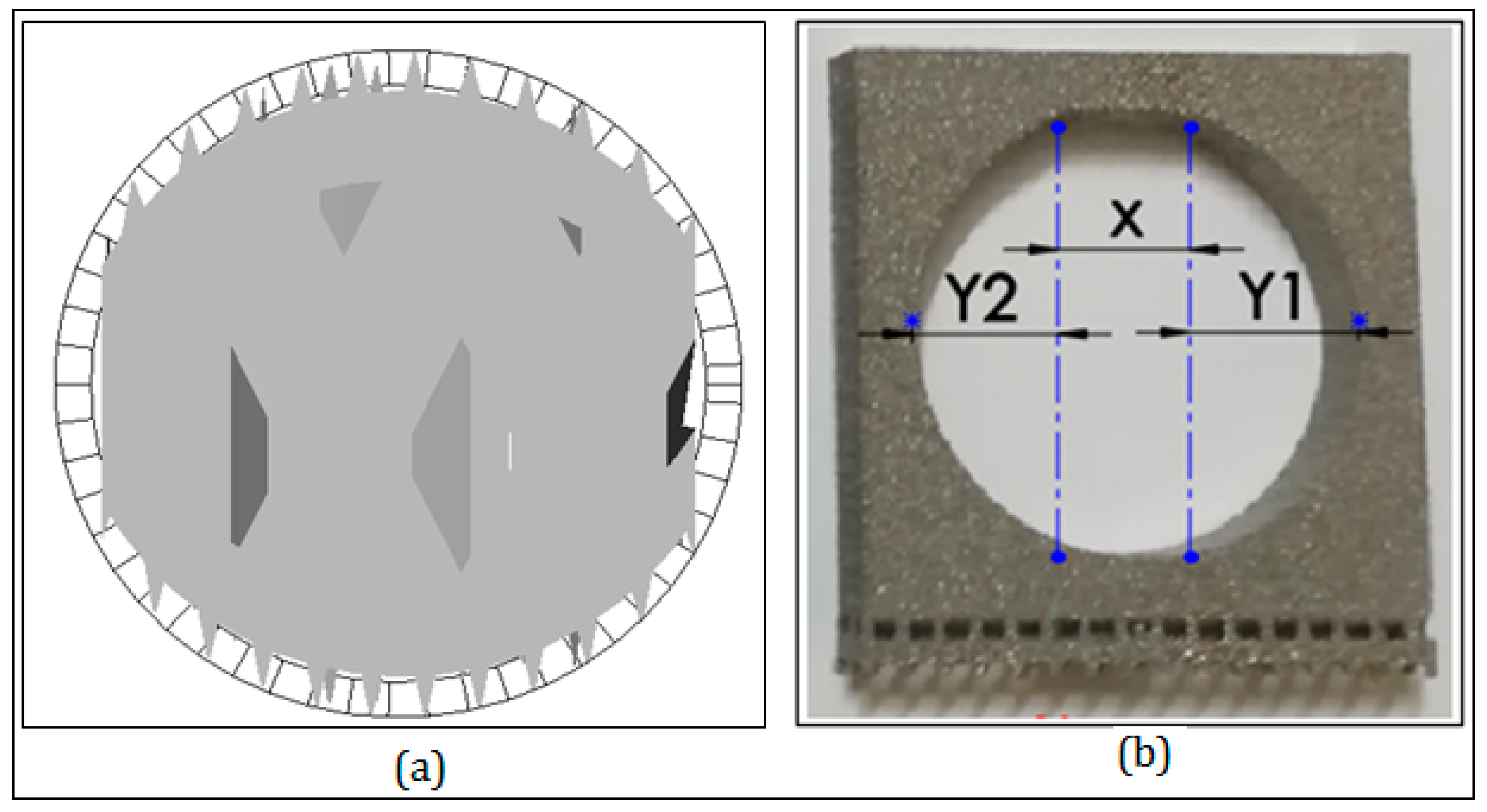
Figure 11.
(a) All fabricated test specimens; (b) Test specimens without and with support structures.
Figure 11.
(a) All fabricated test specimens; (b) Test specimens without and with support structures.

Figure 12.
Fabricated holes without support structures.

Figure 13.
Hole without and with support structure.

Figure 14.
Cylindricity of holes fabricated without support.

Figure 15.
Cylindricity of 5-mm-thick holes with and without support structures.

Figure 16.
Effect of hole size on support removal time.
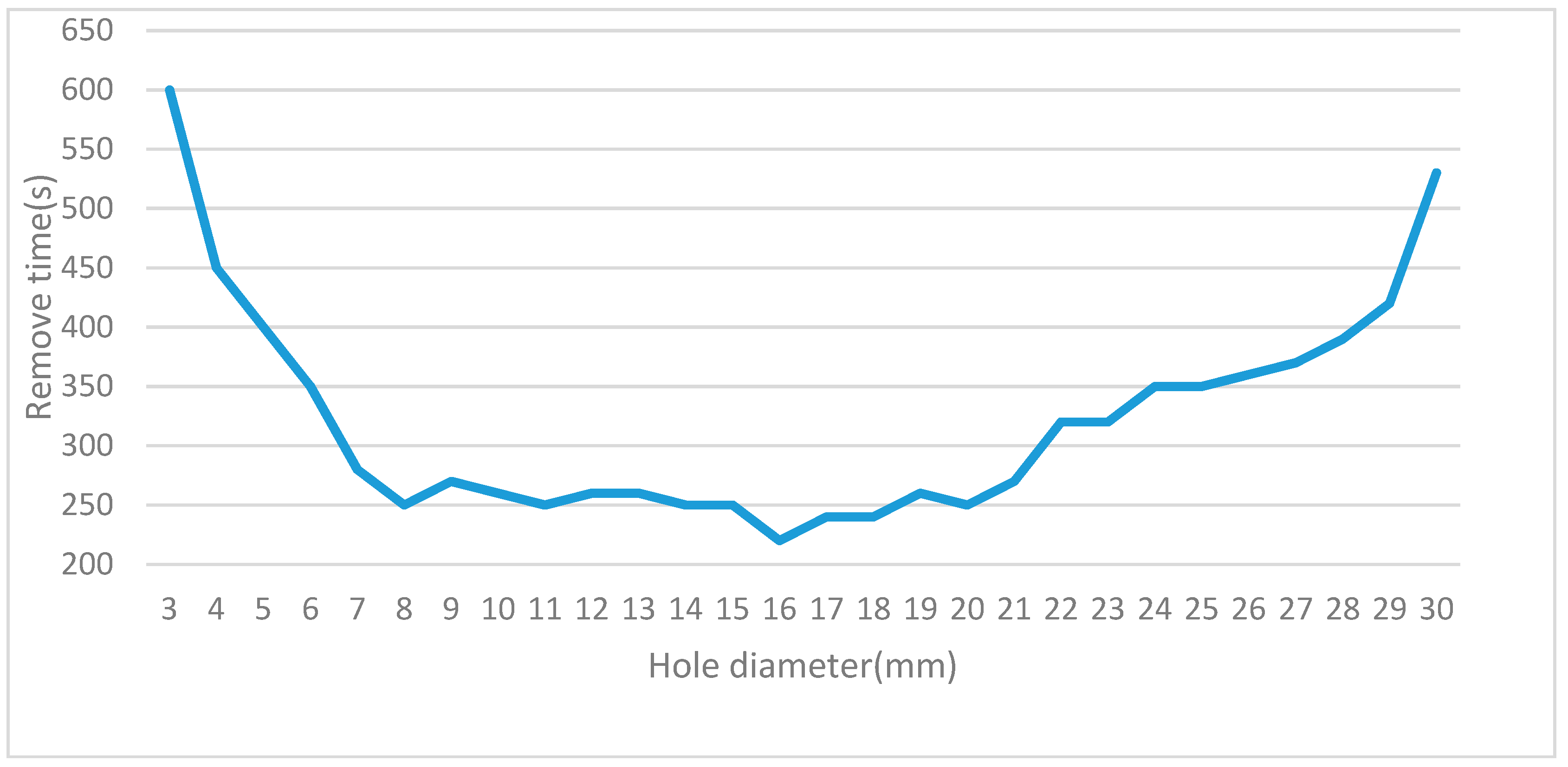
Figure 17.
Relationship between support structure volume and hole diameter and thickness.

Figure 18.
Deformation and self-supporting regions in overhanging holes.

Figure 19.
Holes with different segmentation levels of support structures.

Figure 20.
30-mm-diameter and 5-mm-thick samples.
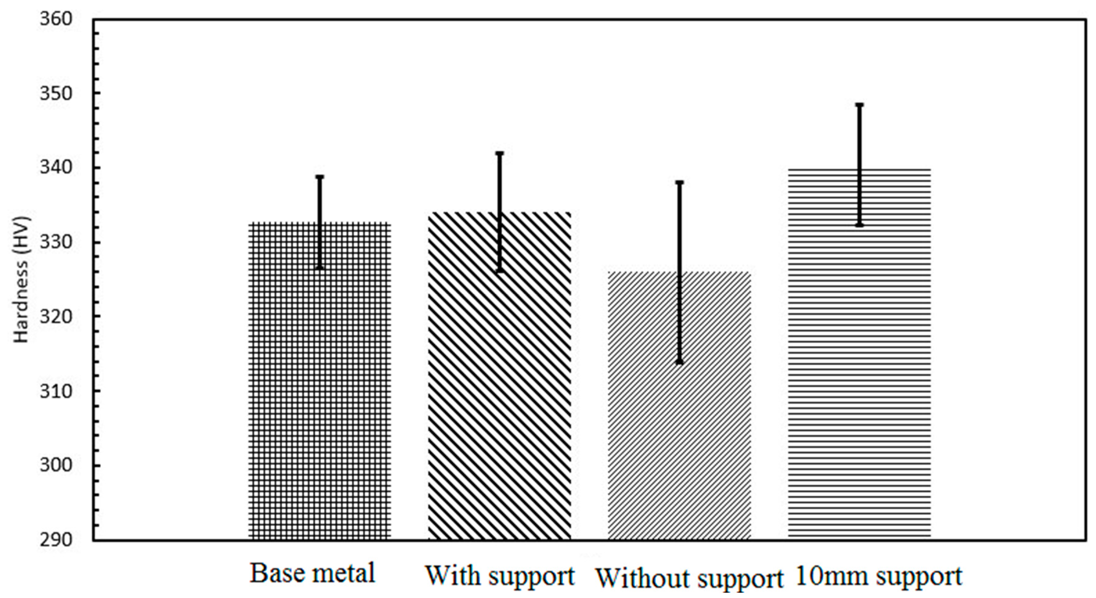
Figure 21.
17-mm-diameter and 5-mm-thick samples.
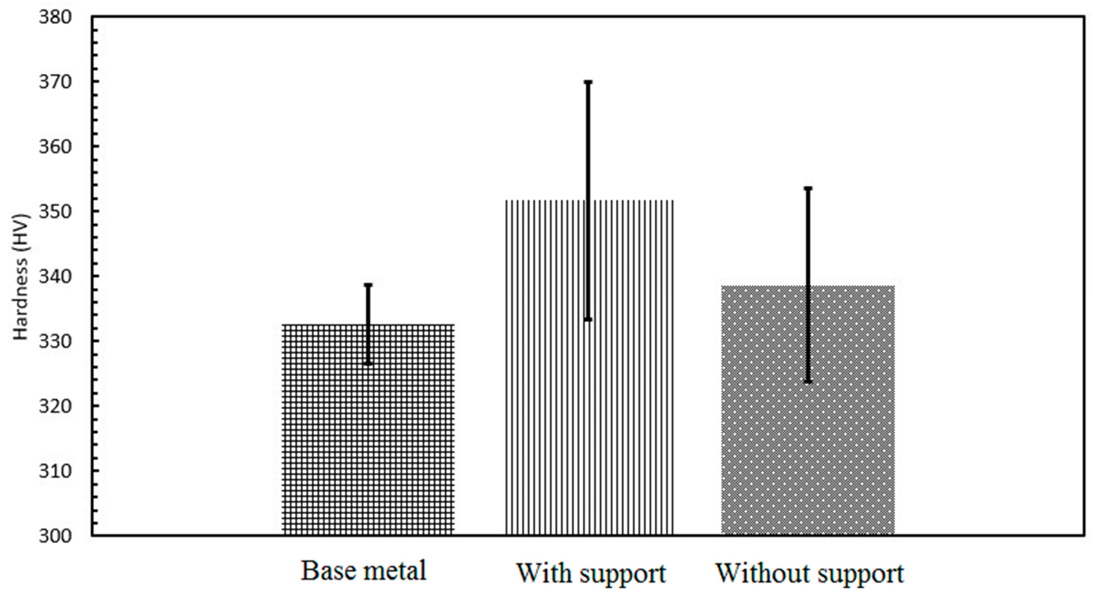
Figure 22.
Optical microscopy of 30-mm-diameter and 5-mm-thick samples (a) with support and (b) without support.
Figure 22.
Optical microscopy of 30-mm-diameter and 5-mm-thick samples (a) with support and (b) without support.
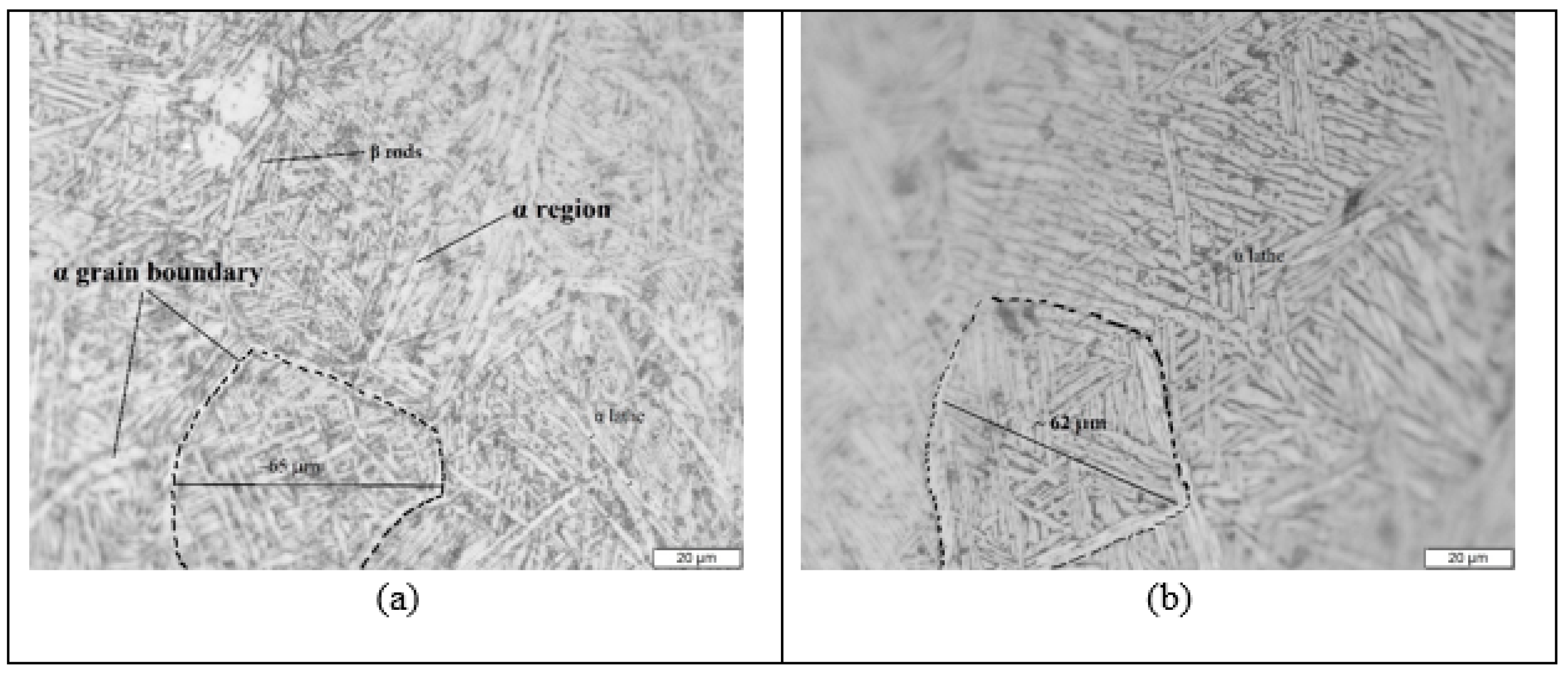
Figure 23.
XRD peak analysis of the 30-mm-diameter, 5-mm-thick samples built with support, without support, and with 10-mm critical support.
Figure 23.
XRD peak analysis of the 30-mm-diameter, 5-mm-thick samples built with support, without support, and with 10-mm critical support.

Figure 24.
SEM images of 30-mm-diameter and 5-mm-thick cylinders, showing: (a) the base metal (b) with support; (c) without support; and (d) with a 10-mm critical support.
Figure 24.
SEM images of 30-mm-diameter and 5-mm-thick cylinders, showing: (a) the base metal (b) with support; (c) without support; and (d) with a 10-mm critical support.
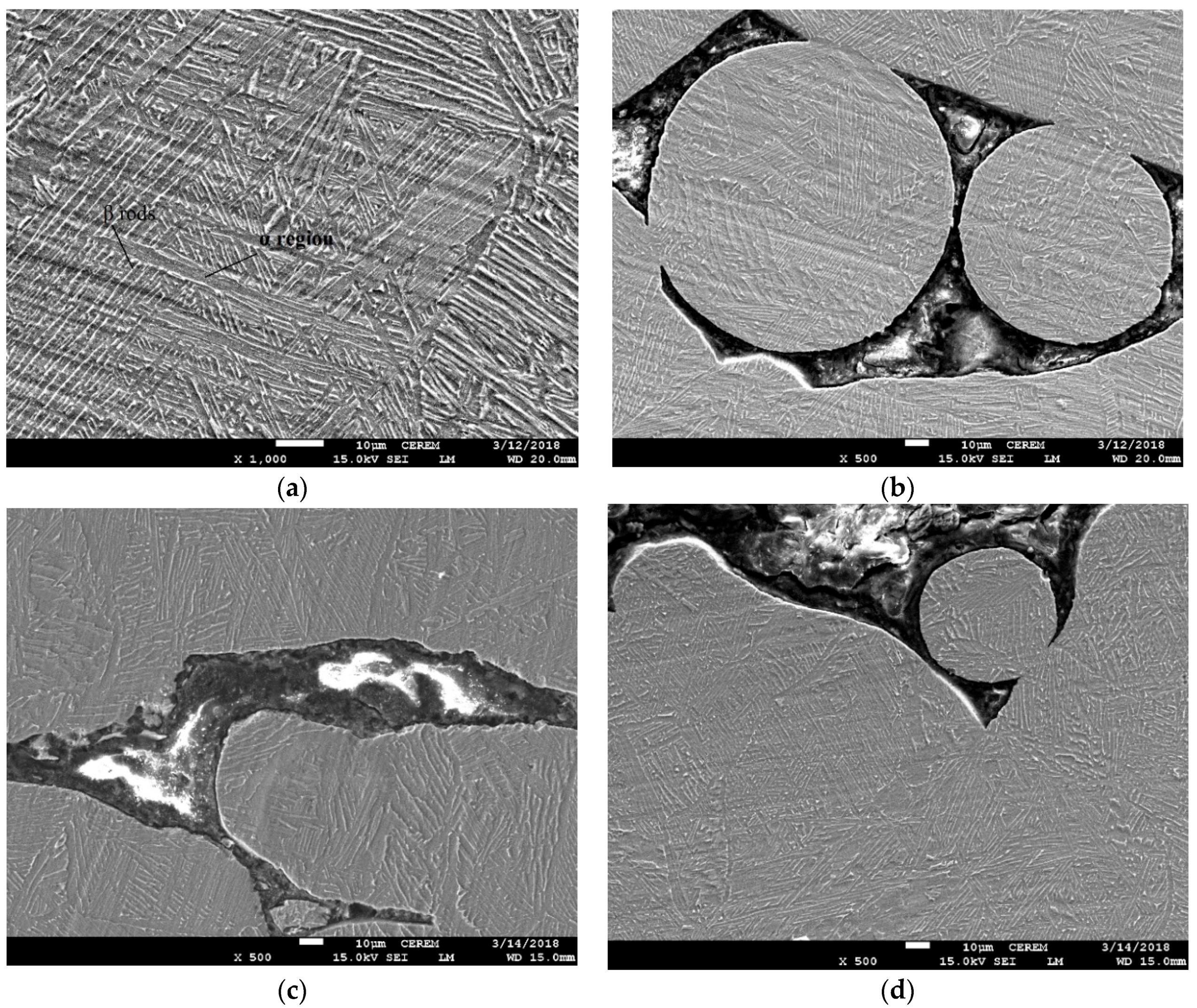
Figure 25.
SEM images of 17-mm-diameter and 5-mm-thick cylinders (a) with support; and (b) without supports.
Figure 25.
SEM images of 17-mm-diameter and 5-mm-thick cylinders (a) with support; and (b) without supports.

Figure 26.
SEM images of 30-mm-diameter cylinders built without support: (a) 5-mm thick; (b) 15-mm thick.
Figure 26.
SEM images of 30-mm-diameter cylinders built without support: (a) 5-mm thick; (b) 15-mm thick.
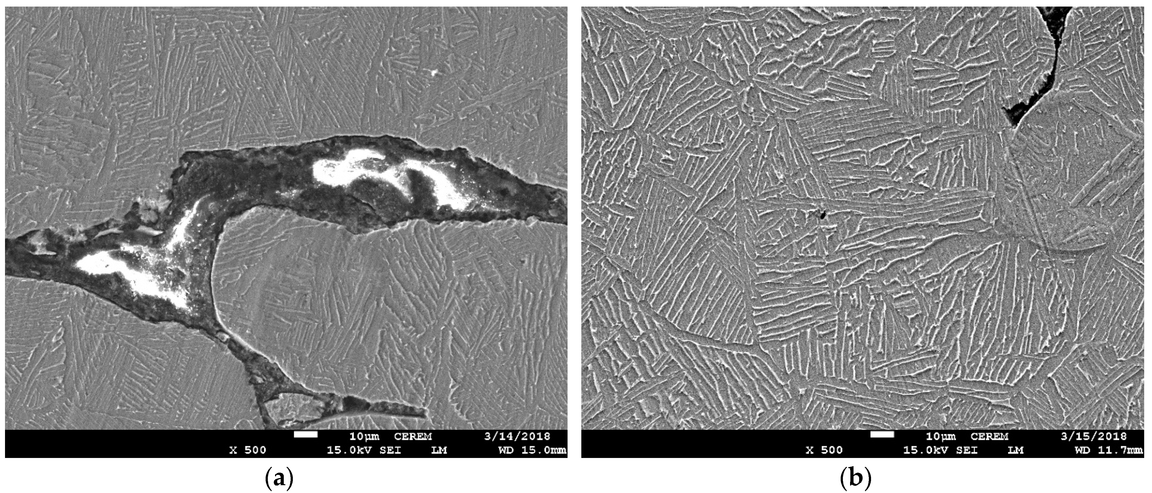
Figure 27.
SEM images of 5-mm-thick cylindrical samples built without support: (a) 30-mm diameter; and (b) 17-mm diameter.
Figure 27.
SEM images of 5-mm-thick cylindrical samples built without support: (a) 30-mm diameter; and (b) 17-mm diameter.

Table 1.
Chemical composition of the Ti6Al4V powder.
| Element | Al | V | C | Fe | O | Ti |
|---|---|---|---|---|---|---|
| Weight % | 6.04 | 4.05 | 0.013 | 0.0107 | 0.13 | Bal. |
© 2018 by the authors. Licensee MDPI, Basel, Switzerland. This article is an open access article distributed under the terms and conditions of the Creative Commons Attribution (CC BY) license (http://creativecommons.org/licenses/by/4.0/).
Share and Cite
MDPI and ACS Style
Ameen, W.; Al-Ahmari, A.; Mohammed, M.K.; Mian, S.H. Manufacturability of Overhanging Holes Using Electron Beam Melting. Metals 2018, 8, 397. https://doi.org/10.3390/met8060397
AMA Style
Ameen W, Al-Ahmari A, Mohammed MK, Mian SH. Manufacturability of Overhanging Holes Using Electron Beam Melting. Metals. 2018; 8(6):397. https://doi.org/10.3390/met8060397
Chicago/Turabian StyleAmeen, Wadea, Abdulrahman Al-Ahmari, Muneer Khan Mohammed, and Syed Hammad Mian. 2018. "Manufacturability of Overhanging Holes Using Electron Beam Melting" Metals 8, no. 6: 397. https://doi.org/10.3390/met8060397
Note that from the first issue of 2016, this journal uses article numbers instead of page numbers. See further details here.