Article

Dissimilar Materials Joining of Carbon Fiber Polymer to Dual Phase 980 by Friction Bit Joining, Adhesive Bonding, and Weldbonding

1
Materials Science and Technology Division, Oak Ridge National Laboratory, Oak Ridge, TN 37830, USA
2
Central Advanced Research and Engineering Institute, Hyundai Motor Company, Uiwang, Gyeonggi 16802, Korea
3
Center for Nanophase Materials Science, Oak Ridge National Laboratory, Oak Ridge, TN 37830, USA
4
Neutron Scattering Division, Oak Ridge National Laboratory, Oak Ridge, TN 37830, USA
*
Author to whom correspondence should be addressed.
Metals 2018, 8(11), 865; https://doi.org/10.3390/met8110865
Submission received: 11 September 2018 / Revised: 19 October 2018 / Accepted: 19 October 2018 / Published: 24 October 2018
(This article belongs to the Special Issue Science, Characterization and Technology of Joining and Welding)

Abstract

:
In the present work, joining of a carbon fiber-reinforced polymer and dual phase 980 steel was studied using the friction bit joining, adhesive bonding, and weldbonding processes. The friction bit joining process was optimized for the maximum joint strength by varying the process parameters. Then, the adhesive bonding and weld bonding (friction bit joining plus adhesive bonding) processes were further developed. Lap shear tensile and cross-tension testing were used to assess the joint integrity of each process. Fractured specimens were compared for the individual processes. The microstructures in the joining bit ranged from tempered martensite to fully martensite in the cross-section view of friction bit-joined specimens. Additionally, the thermal decomposition temperature of the as-received carbon fiber composite was studied by thermogravimetric analysis. Fourier-transform infrared–attenuated total reflectance spectroscopy and X-ray diffraction measurements showed minimal variations in the absorption peak and diffraction peak patterns, indicating insignificant thermal degradation of the carbon fiber matrix due to friction bit joining.

1. Introduction

Achieving lightweight, multi-material auto body structures is a critical goal for the automotive industry to comply with government regulations (i.e., to improve fuel efficiency and reduce greenhouse gas emissions) [1,2]. Currently, four types of lightweight materials—high-strength aluminum alloys, magnesium alloys, ultra-high-strength/advanced high-strength steels (AHSSs), and polymer composites (i.e., carbon fiber-reinforced polymers (CFRPs) and glass fiber-reinforced polymers)—have been identified as substitutes for current steel and/or cast iron auto body structures. The selection of lightweight materials should be carefully explored to produce multi-material structures while satisfying the structural stability and safety performance requirements of vehicles.
Although various combinations of the four candidate materials are possible for potential lightweight vehicles, one of the most interesting material combinations is CFRPs and AHSSs. This is because CFRPs have high mechanical strength with a high strength-to-weight ratio [3,4]. Additionally, a high-strength dual-phase (DP) steel with good mechanical properties [5,6] could be used as a thinner-gauge substitute in existing vehicle structures, leading to substantial weight reductions. However, because of the physical and chemical dissimilarities of individual materials, the development of suitable joining technologies is essential for enabling multi-material auto bodies. Recently, extensive research has been conducted for joining carbon fiber composites to various metals (e.g., aluminum or magnesium alloys), using laser welding [7,8], friction stir blind riveting [9], friction spot joining [10,11,12], ultrasonic welding [13], adhesive bonding [14], friction lap welding [15,16], friction-based injection clinching joining [17], self-piercing riveting [18,19], and hybrid bonding (adhesive + mechanical fastening) [20,21,22]. In addition, very limited work has been focused on joining carbon fiber composites to steel [8,14,23,24]. However, the hole clinching and self-piercing rivet processes have been shown to be difficult to apply to AHSSs (σTS > 780 MPa) [25,26,27]. For this reason, no previous study has attempted to join carbon fiber composites to DP980, potentially because of the limitations of the joining mechanism for each individual process. Although adhesive bonding can be used for CFRPs and different grades of AHSSs, weak peel strength and environmental degradation are key concerns [28]. Therefore, none of the joining technologies mentioned is an easy or the sole way to join a carbon fiber composite and DP980.
In the present work, the authors applied the friction bit joining (FBJ) process to spot-weld carbon fiber composites to DP980. Initially, various welding parameters were used to achieve the highest lap joint strength for FBJ specimens. Next, adhesive bonding and weldbonding (FBJ + adhesive) processes were further developed for the selected materials. The joint integrity for each process was assessed by lap shear tensile and cross-tension testing. Fractured samples were observed and compared for the individual processes. Vickers microhardness was measured on the cross-sectioned FBJ samples to characterize hardness profile changes due to the evolution of microstructures during the joining process. Optical and scanning electron microscopy were used to analyze the interfaces between the joining bit and the CFRP. Additionally, thermogravimetric analysis (TGA) was conducted to study the thermal decomposition temperature of the as-received CFRP. In a cross-sectioned FBJ specimen, Fourier transform infrared–attenuated total reflectance (FTIR-ATR) spectroscopy and X-ray diffraction (XRD) were used to study the thermal degradation of the CFRP close to the joining bit.

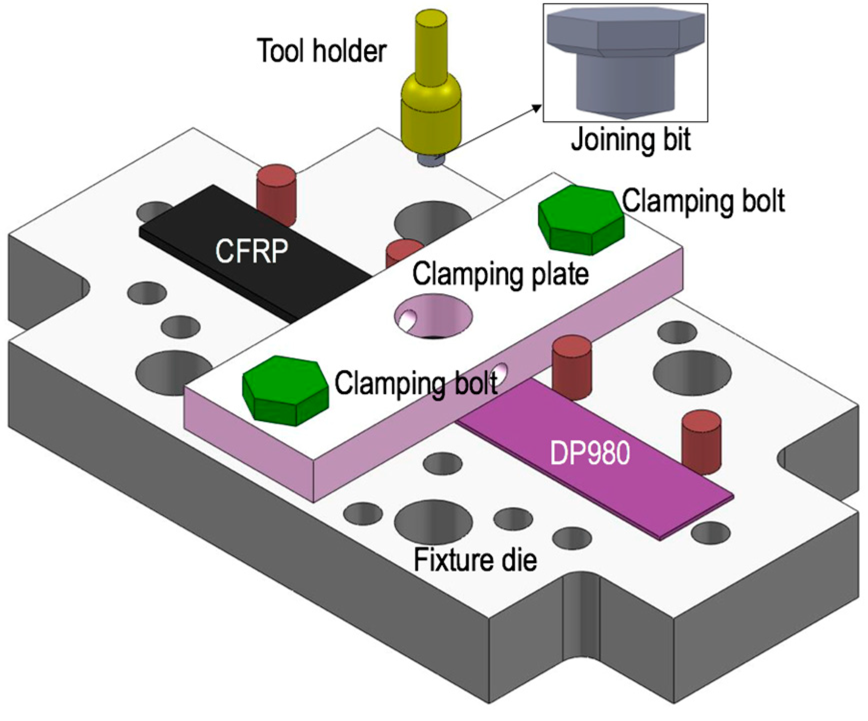
2. Materials and Methods

For the study, the authors purchased a commercially available carbon fiber composite with 2.0 mm-thick epoxy resin (TB Carbon PN.008, Tg = 120 °C) laminate reinforced with 34–36 wt% of unidirectional carbon fibers (CP150NS, TB Carbon, Yangsan-si, Korea), which was used as a top sheet material. The physical properties of carbon fiber are summarized in Table 1. The stacking sequence of the carbon fiber layers followed the configuration [0°/45°/90°] with four plies. The tensile strength of carbon fiber composites was measured at 655 MPa. A 1.2 mm-thick DP980 was used as a bottom sheet material. Joining bits were fabricated using the American Iron and Steel Institute (AISI, Washington, DC, USA) 4140 alloy steel. The joining bit head was a hexagonal shape with 9.525 mm in width. The shank diameter and length of joining bit were 6.6 and 4.57 mm, respectively.
Nominal chemical compositions and mechanical properties of each material are provided in Table 2 and Table 3. Each material was cut and prepared with coupon dimensions of 100 mm in length × 25 mm in width for lap joint specimens. The overlap area for the lap joint configuration was 25 × 25 mm2. A cross-tension specimen composed of carbon fiber composite and DP980 had coupon dimensions of 150 mm in length × 50 mm in width [25]. The hole size in the cross-tension specimen was 20 mm. The overlap area for the cross-tension specimen was 50 by 50 mm2. Before the materials were joined, acetone and isopropyl alcohol were used to remove any dirt and grease on both material surfaces.
An STA 449 F1 Jupiter simultaneous thermal analyzer (Netzsch Gerätebau-GmbH, Selb, Germany) was used to investigate the thermochemistry of the as-received carbon fiber composite. Differential scanning calorimetry (DSC) was coupled with thermogravimetry with the aim of determining incipient decomposition temperatures. Disc-shaped specimens taken from the as-received carbon fiber composite, weighing 61.98 mg with a diameter of 6.4 mm and a thickness of around 2 mm, were prepared to fit snugly and flush to the bottom of platinum crucibles supplied by Netzsch (Selb, Germany). During FBJ, the peak temperature in the joining bit can be expected to exceed the austenite transition temperature (A3) of steels [29]. For this reason, the maximum temperature was set at 1000 °C for the thermogravimetry measurements. The samples were heated at a constant ramp rate of 5 °C/min to 1000 °C in flowing ultra-high-purity argon gas at 100 cc/min. The change in weight and a microvolt signal, due to the temperature difference between the sample and the reference crucible, were recorded as functions of temperature.
FBJ is a two-stage joining process [30,31]. In the first stage (Figure 1b), the joining bit cuts and plunges into the top material using a spindle speed of 2000 rev·min−1 and a plunge rate in the z-direction of 171.5 mm·min−1. In the second stage (Figure 1c), the joining bit is bonded to the bottom steel sheet by frictional heat and z-direction axial force. Various welding conditions were tested to achieve the highest lap shear strength. After preliminary tests, the total plunge depth by the joining bit and joining feed rate were fixed at 4.32 mm and 171.5 mm·min−1, respectively. Then, different joining speeds in the range from 1500 to 2500 rev·min−1 were used to achieve the maximum lap joint strength. Figure 2 is a schematic view of the lap joint-configured sample holder, tool holder, joining bit, and clamping parts used for the present work.
A commercially available adhesive, 3M Scotch-weld Epoxy DP460, was used for the adhesive bonding and the weld bonding (FBJ + adhesive) processes. An applicator with a mixing nozzle that supplies a 2:1 mixing ratio of resin to a hardener was used. A 250 μm glass bead was applied in the joint area to maintain a constant adhesive bond line thickness. Then the adhesive was cured in an oven for 1 h at 60 °C, as recommended by the manufacturer. For weldbonding, FBJ was conducted on a cured specimen with the same welding process parameters.
Lap shear tensile tests were conducted using an MTS hydraulic test frame at a cross head rate of 10 mm·min−1 and at room temperature. Spacers (25 × 25 mm2) were used to grip the samples to prevent bending of the specimen during the lap shear test. The gripping area on the both ends was 25 × 25 mm2. Similarly, cross-tension tests were conducted with the same cross head rate as used for the lap shear tensile tests and at room temperature. Each mechanical test was triplicated for each joining process.
For cross-sectional analysis, FBJ samples were cross-sectioned and then mounted in epoxy resin. Then the samples were finely polished using a common metallographic procedure. A 5% Nital solution was used to etch the sample surface to reveal the microstructure. An optical microscope (Nikon Epiphot, Nikon, Tokyo, Japan) and a high-resolution scanning electron microscope (SEM) (JELO 6500 FEG-SEM, Hitachi High-Technologies, Krefeld, Germany) were used to characterize the cross sections of FBJ specimens. A Leco LM100 AT (Leco, Saint Joseph, MI, USA) was used to measure the Vickers microhardness of FBJ specimens with the following conditions: a 500 g load, 13 s of dwell time, and 250 μm spacing.
XRD patterns of a thermally affected carbon fiber composite directly mated with DP980 and the as-received CFRP were recorded using a PANalytical X’Pert Pro-MPD powder diffractometer (Malvern Panalytical, Amelo, The Netherlands) equipped with a Si-based position-sensitive one-dimensional detector and a nickel-filtered copper Kα radiation source. For the measurements, X-ray was generated at 45 kV/40 mA at a beam wavelength of λ = 1.5416 × 10⁻¹⁰ m (copper Kα radiation). The XRD measurements of the epoxy/carbon fiber multilayer were carried out in the reflection mode; hence, the XRD probed the surface morphology of the outer epoxy layer.
FTIR-ATR spectroscopy (Bruker Optik GmbH, Ettlingen, Germany) with a Bruker Lumos FTIR microscope in the ATR mode was used to probe the surface of the epoxy composite in close proximity to the joining bit. The spectra represented an average of 128 scans with a spectral resolution of 4 cm−1. Spectra from five different spots with a 300 µm spacing over a 1000 µm distance were obtained using a line scan that originated at the interface between the joint bit and the carbon fiber composite. A spectrum for the as-received carbon fiber composite was also collected as a reference.

3. Results and Discussion

3.1. Thermogravimetry and Differential Scanning Calorimetry Measurements for the As-Received Carbon Fiber Composites

The results of the thermogravimetry-coupled DSC analysis of the as-received CFRP sample are plotted in Figure 3. The STA 449 F1 instrument and software use the fundamentals of heat-flux DSC to determine both reaction temperatures and the associated enthalpy (ΔHrxn). Figure 3 indicates the as-received CFRP tested is thermally stable up to 290.5 °C. The mass of the sample precipitously dropped immediately after the beginning of a sharp exothermic DSC signal. The sharp exothermic peak could be due to interactions among leftover elements that might occur during thermal degradation of the epoxy.

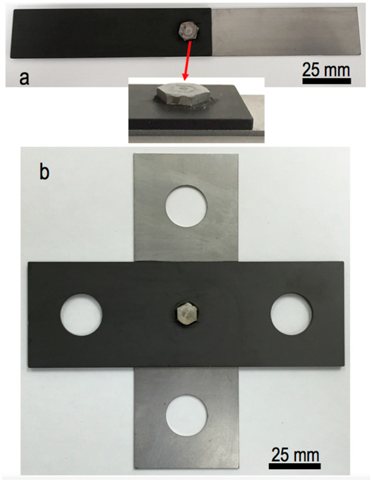
3.2. Lap Shear Tensile Testing and Fractorgraphy

The assembly for lap shear testing of the FBJ specimen is presented in Figure 4a. Lap shear tensile testing was conducted to determine the static mechanical strength of the FBJ joints under optimized welding conditions, as already summarized in Table 4.
A summary of the average lap joint failure loads and lap shear strengths for each process is plotted in Figure 5. A maximum lap joint failure load of 6.4 kN was achieved for FBJ specimens. The average lap shear failure load was 6.0 kN when three samples were repeatedly tested. The average lap shear failure loads for adhesive-bonded and weld-bonded specimens were 14.8 and 13.3 kN, respectively. For weld-bonded coupons, a small reduction in the lap joint strength (approximately 10%), compared with the adhesive-bonded coupons, was attributed to thermal degradation of the cured adhesive on the periphery of the joining bit due to frictional heating. However, the lap joint failure load of the weld-bonded specimen was almost twice higher than the failure load for the FBJ-only coupon, indicating the mechanical joint strength was improved because the load distribution was shared between the adhesive bonding and FBJ.
Similarly, Squires et al. [29] observed an improvement in the mechanical joint strength for a high-strength aluminum alloy joined to steel by weld bonding. Di Franco et al. [32] also found increased joint strength when self-pierce riveting was combined with adhesive bonding to join a carbon fiber composite and aluminum sheet AA2024-T6. In addition, the presence of an adhesive layer in the joint area can effectively act as an insulator or a barrier against corrosion media, resulting in improvement in the corrosion resistance [33,34,35]. For this reason, weld bonding of carbon fiber composites to lightweight metals may have the highest success rates for protecting against corrosion under environmental conditions and for improving mechanical joint performance.
Because of the different joining processes, joint dimensions, and material combinations, a direct comparison of FBJ, adhesive-bonded, and weld-bonded joint strength with data from the available literature is not possible. For this reason, the maximum lap shear strength for the FBJ coupon was calculated based on the shank diameter (6.6 mm) of the joining bit, yielding a value of 186 MPa. Maximum lap shear strengths of 27.3 and 22.5 MPa were calculated for the adhesive bonding and weld bonding cases, respectively, by using the overlap area (25 × 25 mm2) in the lap joint. This normalized calculation has been used as a common practice [11,36]. Table 5 allows readers to compare the results from this study with values for current state-of-the-art techniques for joining polymers to metals. Again, direct comparison of different processes would be not applicable, as previously explained, but general information of various joining techniques can be beneficial to readers. Overall, the results from this study show higher or comparable lap shear strengths, compared with the strengths demonstrated by other joining technologies.
Figure 6 shows fractography results for different specimens from lap shear tensile testing. For FBJ, the joining bit and DP980 were still intact, indicating good consolidated joining between the joining bit and DP980. The failure mode was found to be shear out—one of the common fracture modes (i.e., net tension, shear out, cleavage, and bearing) for composite joints—in cases, where the distance between the hole edge and the edge of the laminate was small [37]. For adhesive bonding, delamination of the carbon fiber composite matrix was observed, indicating good adhesion between the carbon fiber composite surface and the adhesive. Mixed failure modes (i.e., shear out and delamination of carbon fiber composites) were observed for weld-bonded samples, as a result of combining two joining processes (i.e., FBJ and adhesive bonding).

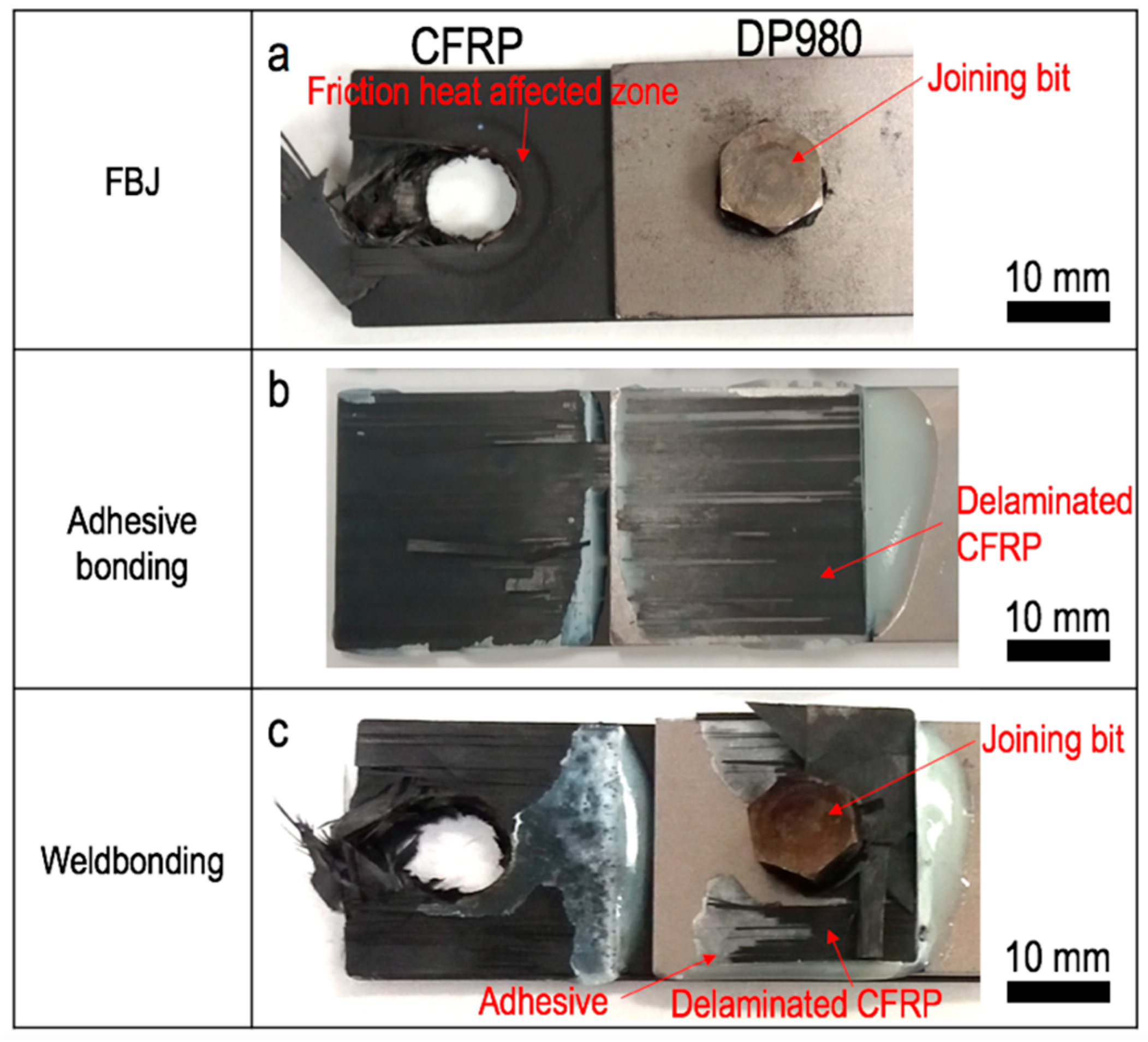
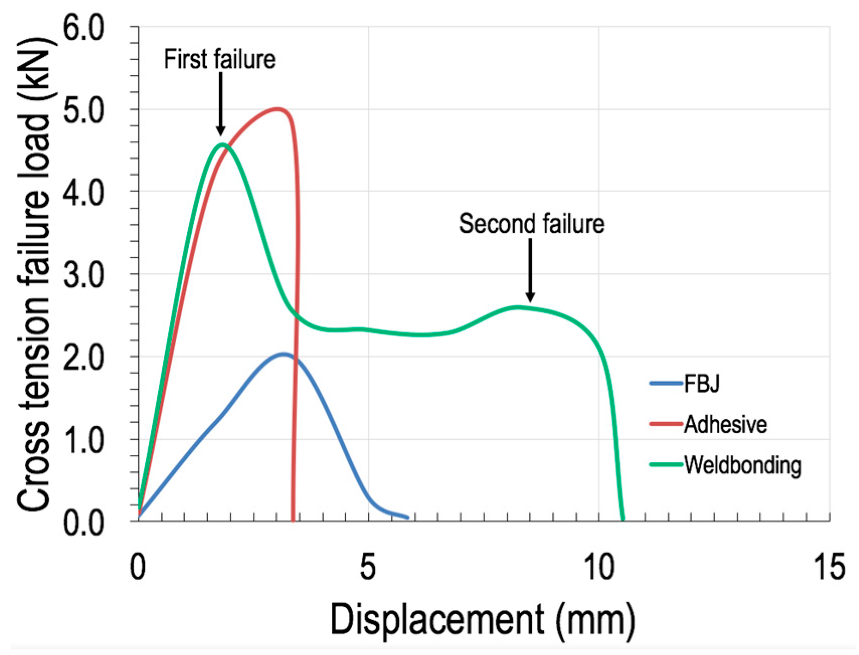
3.3. Cross Tension Testing and Fractorgraphy

Examples of final assembled cross-tension specimens joined by FBJ are shown in Figure 4b. Representative load and displacement curves from cross-tension testing of the individual processes are plotted in Figure 7. For FBJ, the peak failure load was found to be 2 kN; a maximum failure load of 4.82 kN was achieved for the adhesive-bonded specimen. Two peak failure loads (4.51 and 2.59 kN) were found for the weld-bonded specimen because of the nature of the two combined joining processes. Although the peak failure loads for adhesive-bonded (4.82 kN) and weld-bonded (4.51 kN) specimens were similar, different failure modes were seen from the load and displacement curves. The adhesive-bonded sample immediately failed at a displacement distance of 3.35 mm, whereas the weld-bonded specimen failed after reaching the second peak load. This is because the friction bit joint remained after the first failure of the adhesive-bonded coupon. It is worth mentioning that the second peak failure load for the weld-bonded sample was close to the maximum failure load of the FBJ-only sample.
Absorption energy is the ability to absorb energy under the mechanical testing condition, which is important for crash or dynamic performance for autobody structures. Absorption energy for each joining process was calculated by integration of load and displacement curved in Figure 7. Summary of peak failure load, absorption energy, displacement at failure for each joining process is presented in Table 6. Absorption energy of weld-bonded specimen is nearly twice higher than the absorption energy of adhesive bonded case. Therefore, the weld bonding process can provide improved structural safety performance compared with adhesive bonding and FBJ only.
Fractography results for cross-tension-tested individual specimens are provided in Figure 8. For the FBJ specimen, the joining bit and DP980 remained in an intact condition, indicating good metallurgical bonding between them, whereas the carbon fiber composite was pullout. For adhesive-bonded specimens, mixed failure modes were observed, such as adhesive failure (i.e., fracture at the interface between the adhesive and the carbon fiber composite) and some delamination of the carbon fiber composite layer, as shown in Figure 8b. Finally, the weld-bonded specimens showed complex failure modes, including carbon fiber composite pullout, some adhesive failures, and some delamination of the composite matrix, as presented in Figure 8c. These mixed failure modes for weld-bonded samples are thought to have resulted from the combined FBJ and adhesive bonding processes.

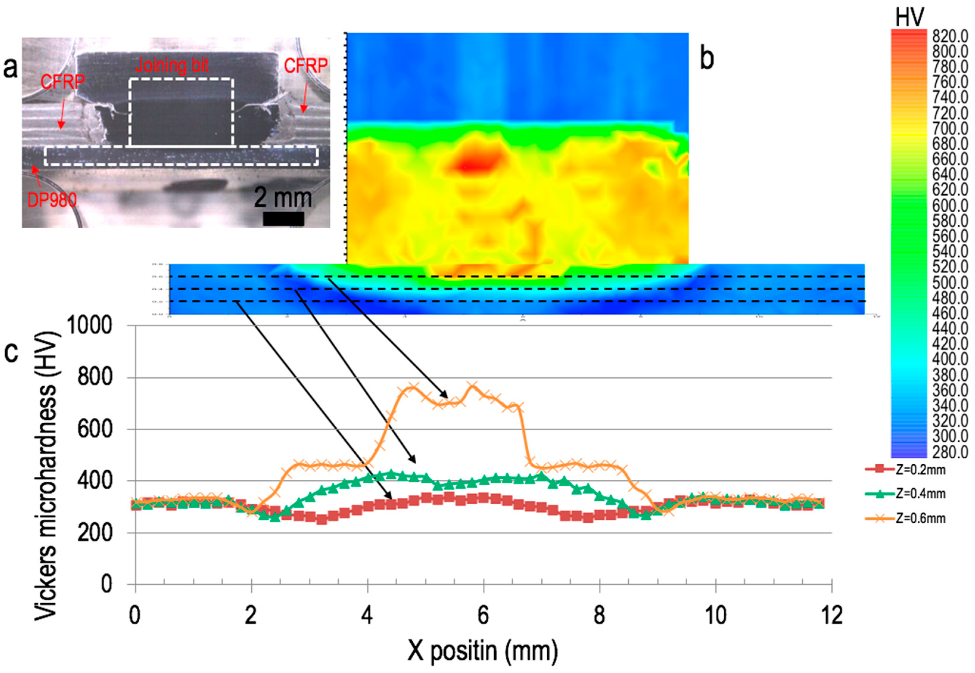
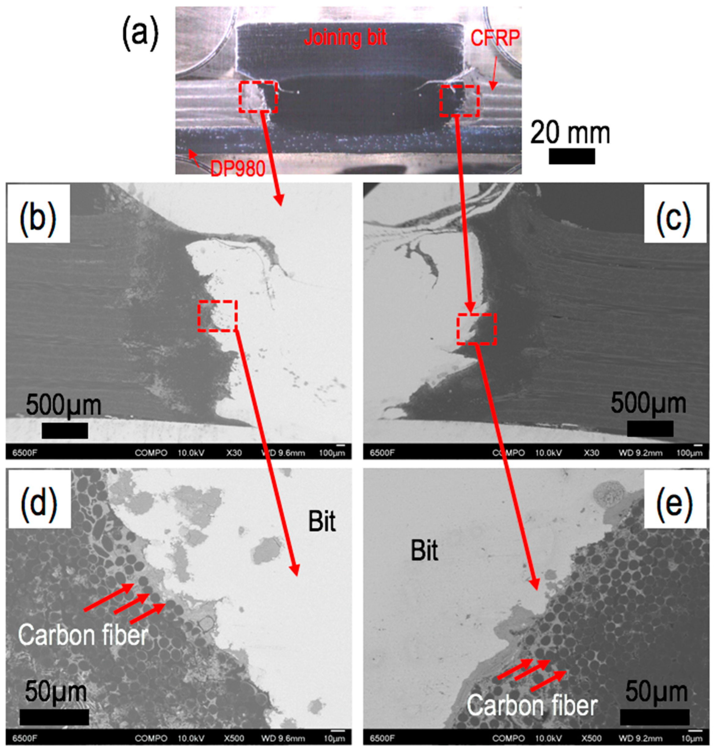
3.4. Cross Sectional Analysis of Firction Bit-Joined Specimen

The Vickers microhardness distribution in the joining bit and DP980 (Figure 9a) is mapped in Figure 9b, and microhardness profiles along the x direction with three dashed lines are shown in Figure 9c. The average Vickers microhardness values for the joining bit and DP980 were measured at 322 and 320 HV, respectively. In the joining bit, the Vickers microhardness increased up to 760 HV because of the evolution of the microstructure from tempered martensite to fully martensite, as a result of rapid heating and cooling cycle during the joining stage. This result indicates that the peak temperature during the heating cycle was above the A3 temperature of typical steels [29,30].
Figure 10 shows optical and magnified SEM images from the cross-sectioned FBJ specimen. In Figure 10a, consolidated bonding between the joining bit and DP980 is observed without any cracks. Figure 10b,c shows SEM images near the joining bit and carbon fiber composite. At the distance ranging from 0.5 to 1.0 mm away from the edge of the joining bit, the gap between the CFRP and the joining bit was filled by the CFRP matrix. In this region, carbon fibers near the joining bit were redirected by the rotational motion of the joining bit during the joining step, as seen in Figure 10d,e. This redirection of the carbon fibers was also seen in other studies, in which rotation of a rivet occurred [38]. The remaining area was the base CFRP material, in which the carbon fibers were aligned as manufactured.
Based on the joint configuration and bonding mechanism, the CFRP matrix closer to the polymer and metal (i.e., joining bit and DP980) interface will be affected by frictional heating generated during the plunge and joining stages, as illustrated in Figure 1b,c. In the plunge stage, the joining bit cuts and plunges into the CFRP, resulting in increasing temperature in the CFRP. Because no outgassing was observed in the plunge stage during the FBJ process, the peak temperature generated in the carbon fiber composite was expected to be lower than the decomposition temperature of 290.5 °C for the composite.
During the joining step, great frictional heat is generated when the joining bit engages the steel substrate with a higher spindle rotational speed and a higher axial plunge load. Two scenarios of frictional heat conduction can be anticipated. First, frictional heat will radially diffuse into the steel substrate from the joining bit. Then, frictional heat will be conducted from the bottom steel sheet to carbon fiber composites when they directly contact the steel substrate, as a result of being clamped to it, as shown in Figure 2. However, the peak temperature of the steel substrate will decrease because of the large thermal mass from the fixture substrate. Figure 6a shows a thermally affected radial area of the carbon fiber composite, which whitened slightly. XRD was used to find any noticeable peak changes in the thermally affected radial areas of the CFRP and as-received carbon fiber composites. Figure 11 exhibits the typical amorphous phase of the epoxy [39]. Note that the XRD patterns of the two zones are essentially identical, implying that the thermal degradation is ignorable.
Next, heat conduction from the joint bit to the surrounding carbon fiber composite was considered. As mentioned earlier, the peak temperature of the joining bit during the joining step can exceed the A3 temperature, as evidenced by the Vickers microhardness measurements. The high temperature can lead to localized degassing of the polymer matrix adjacent to the joining bit due to the relatively short weld time (~0.8 s) and low thermal diffusivity (1.2–2.0 m2·s−1) of the carbon fiber composite [40,41]. For this reason, the remaining polymer composite was not expected to suffer from frictional heat. A cross-sectioned FBJ sample was subjected to FTIR-ATR spectroscopy to examine the surface of the epoxy composite in close proximity to the joining bit to determine if frictional heat from the joining process led to significant polymer degradation. Figure 12 shows characteristic absorption peaks for epoxy resin systems at five different locations and for a reference layer [42,43]. Although there are minor variations in the data, they are qualitatively similar; it can be concluded that if any thermal degradation occurs during the joining process, it is insignificant.

4. Conclusions

Joining of carbon fiber composites and DP980 was successfully demonstrated by FBJ, adhesive bonding, and weld bonding. Average lap shear failure peak loads were found to be 6.0, 14.8, and 13.3 kN for FBJ, adhesive-bonded, and weld-bonded specimens, respectively. The obtained lap shear failure load for each joining process was higher than or comparable to the joint strengths found in the open literature. Cross-tension failure loads were 2.0 and 4.82 kN for FBJ and adhesive-bonded coupons, respectively; and the weld-bonded specimens showed two distinctive peak failure loads of 4.51 and 2.59 kN due to the combination of FBJ and adhesive joining. Thermogravimetry measurements indicated that the as-received CFRP will decompose starting at 290.5 °C. FTIR and XRD results showed limited variations in the peak patterns, including insignificant thermal degradation of the carbon fiber matrix as a result of FBJ.

Author Contributions

Conceptualization, Y.C.L., H.P. and Z.F.; methodology, Y.C.L., H.P., J.J.; investigation, J.W.M., B.S.L., J.K.K. and Z.W.; writing of the original draft preparation, Y.C.L.; writing of review and editing, Y.C.L. and Z.F.; supervision, Z.F.

Funding

This research was funded by Hyundai Motor Company in Korea under the contract number NFE-15-05748.

Acknowledgments

FTIR and XRD measurements for CFRP were conducted at the Center for Nanophase Materials Sciences, which is a DOE Office of Science User Facility. Oak Ridge National Laboratory is managed by UT-Battelle, LLC, for the US Department of Energy under contract DE-AC05-00OR22725. This manuscript has been authored by UT-Battelle, LLC, under contract DE-AC05-00OR22725 with the US Department of Energy (DOE). The US government retains and the publisher, by accepting the article for publication, acknowledges that the US government retains a nonexclusive, paid-up, irrevocable, worldwide license to publish or reproduce the published form of this manuscript, or allow others to do so, for US government purposes. DOE will provide public access to these results of federally sponsored research in accordance with the DOE Public Access Plan (http://energy.gov/downloads/doe-public-access-plan).

Conflicts of Interest

The authors declare no conflicts of interest.

References

  1. Dilthey, U.; Stein, L. Multimaterial car body design: Challenge for welding and joining. Sci. Technol. Weld. Join. 2006, 11, 135–141. [Google Scholar] [CrossRef]
  2. Meschut, G.; Janzen, V.; Olfermann, T. Innovative and highly productive joining technologies for multi-material lightweight car body structures. J. Mater. Eng. Perf. 2014, 23, 1515–1523. [Google Scholar] [CrossRef]
  3. Adam, H. Carbon fibre in automotive applications. Mater. Des. 1997, 18, 349–355. [Google Scholar] [CrossRef]
  4. Edwards, K.L. An overview of the technology of fibre-reinforced plastics for design purpose. Mater. Des. 1998, 19, 1–10. [Google Scholar] [CrossRef]
  5. Bhagavathi, L.R.; Chaudhari, G.P.; Nath, S.K. Mechanical and corrosion behavior of plain low carbon dual-phase steels. Mater. Des. 2011, 32, 433–440. [Google Scholar] [CrossRef]
  6. Mintz, B. Hot dip galvanising of transformation induced plasticity and other intercritically annealed steels. Int. Mater. Rev. 2001, 46, 169–197. [Google Scholar] [CrossRef]
  7. Jung, K.W.; Kawahito, Y.; Katayama, S. Laser direct joining of carbon fibre reinforced plastic to stainless steel. Sci. Technol. Weld. Join. 2011, 16, 676–680. [Google Scholar] [CrossRef]
  8. Jung, K.W.; Kawahito, Y.; Takahashi, M.; Katayama, S. Laser direct joining of carbon fiber reinforced plastic to zinc-coated steel. Mater. Des. 2013, 47, 179–188. [Google Scholar] [CrossRef]
  9. Min, J.; Li, Y.; Li, J.; Carlson, B.E.; Lin, J. Friction stir blind riveting of carbon fiber-reinforced polymer composite and aluminum alloy sheets. Int. J. Adv. Manuf. Technol. 2015, 76, 1403–1410. [Google Scholar] [CrossRef]
  10. Amancio-Filho, S.T.; Bueno, C.; dos Santos, J.F.; Huber, N.; Hage, E., Jr. On the feasibility of friction spot joining in magnesium/fiber-reinforced polymer composite hybrid structures. Mater. Sci. Eng. A 2011, 528, 3841–3848. [Google Scholar] [CrossRef] [Green Version]
  11. Goushegir, S.M.; dos Santos, J.F.; Amancio-Filho, S.T. Friction spot joining of aluminum AA2024/carbon-fiber reinforced poly(phenylene sulfide) composite single lap joints: Microstructure and mechanical performance. Mater. Des. 2014, 54, 196–206. [Google Scholar] [CrossRef]
  12. Esteves, J.V.; Goushegir, S.M.; dos Santos, J.F.; Canto, L.B.; Hage, E., Jr.; Amancio-Filho, S.T. Friction spot joining of aluminum AA6181-T4 and carbon fiber-reinforced poly(phenylene sulfide): Effects of process parameters on the microstructure and mechanical strength. Mater. Des. 2015, 66, 437–445. [Google Scholar] [CrossRef] [Green Version]
  13. Balle, F.; Wagner, G.; Eifler, D. Ultrasonic metal welding of aluminium sheets to carbon fibre reinforced thermoplastic composites. Adv. Eng. Mater. 2009, 11, 35–39. [Google Scholar] [CrossRef]
  14. Anyfantis, K.N.; Tsouvalis, N. Loading and fracture response of CFRP-to-steel adhesively bonded joints with thick adherents—Part I: Experiment. Compos. Struct. 2013, 96, 850–857. [Google Scholar] [CrossRef]
  15. Liu, F.C.; Liao, J.; Gao, Y.; Nakata, K. Effect of plasma electrolytic oxidation coating on joining metal to plastic. Sci. Technol. Weld. Join. 2015, 20, 291–296. [Google Scholar] [CrossRef]
  16. Nagatsuka, K.; Yoshida, S.; Tsuchiya, A.; Nakata, K. Direct joining of carbon-fiber-reinforced plastic to an aluminum alloy using friction lap joining. Compos. B 2015, 73, 82–88. [Google Scholar] [CrossRef]
  17. Abibe, A.B.; Sonego, M.; dos Santos, J.F.; Canto, L.B.; Amancio-Filho, S.T. On the feasibility of a friction-based staking joining method for polymer-metal hybrid structures. Mater. Des. 2016, 92, 632–642. [Google Scholar] [CrossRef]
  18. Zhang, J.; Yang, S. Self-piercing riveting of aluminum alloy and thermoplastic composites. J. Compos. Mater. 2014, 49, 1493–1502. [Google Scholar] [CrossRef]
  19. Haque, R. Quality of self-piercing riveting (SPR) joints from cross-sectional perspective: A review. Arch. Civ. Mech. Eng. 2018, 18, 83–93. [Google Scholar] [CrossRef]
  20. Kelly, G. Load transfer in hybrid (bonded/bolted) composite single-lap joints. Compos. Struct. 2005, 69, 35–43. [Google Scholar] [CrossRef]
  21. Kolesnikov, B.; Herbeck, L.; Fink, A. CFRP/titanium hybrid material for improving composite bolted joints. Compos. Struct. 2008, 83, 368–380. [Google Scholar] [CrossRef]
  22. Chowdhury, N.; Chiu, W.K.; Wang, J.; Chang, P. Static and fatigue testing thin riveted, bonded and hybrid carbon fiber double lap joints used in aircraft structures. Compos. Struct. 2015, 121, 315–323. [Google Scholar] [CrossRef]
  23. Lee, S.H.; Lee, C.J.; Lee, K.-H.; Lee, J.-M.; Kim, B.-M.; Ko, D.C. Influence of tool shape on hole clinching for carbon fiber-reinforced plastics and SPRC440. Adv. Mech. Eng. 2014, 6, 810864. [Google Scholar] [CrossRef]
  24. Wagner, J.; Wilhelm, M.; Baier, H.; Fussel, U.; Richter, T. Experimental analysis of damage propagation in riveted CFRP-steel structures by thermal loads. Int. J. Adv. Manuf. Technol. 2014, 75, 1103–1113. [Google Scholar] [CrossRef]
  25. Sun, X.; Khaleel, M.A. Strength estimation of self-piercing rivets using lower bound limit load analysis. Sci. Technol. Weld. Join. 2005, 10, 624–635. [Google Scholar] [CrossRef]
  26. Abe, Y.; Kato, T.; Mori, K. Self-pierce riveting of three high strength steel and aluminum alloy sheets. J. Mater. Forum 2008, 1, 1271–1274. [Google Scholar] [CrossRef]
  27. Lee, C.-J.; Kim, J.-Y.; Lee, S.-K.; Ko, D.-C.; Kim, B.-M. Parametric study on mechanical clinching process for joining aluminum alloy and high-strength steel sheets. J. Mech. Sci. Technol. 2010, 24, 123–126. [Google Scholar] [CrossRef]
  28. Xiao, G.Z.; Shanahan, M.E.R. Water absorption and desorption in an epoxy resin with degradation. J. Polym. Sci. B 1997, 35, 2659. [Google Scholar] [CrossRef]
  29. Squires, L.; Lim, Y.C.; Miles, M.; Feng, Z. Mechanical properties of dissimilar metal joints composed of DP 980 steel and AA 7075-T6. Sci. Technol. Weld. Join. 2015, 20, 242–248. [Google Scholar] [CrossRef]
  30. Miles, M.P.; Kohkonen, K.; Packer, S.; Steel, R.; Siemssen, B.; Sato, Y.S. Solid state spot joining of sheet materials using consumable bit. Sci. Technol. Weld. Join. 2009, 14, 72–77. [Google Scholar] [CrossRef]
  31. Huang, T.; Sato, Y.S.; Kokawa, H.; Miles, M.P.; Kohkonen, K.; Siemssen, B.; Steel, R.J.; Packer, S. Microstructural evolution of DP980 steel during friction bit joining. Metall. Mater. Trans. A 2009, 40A, 2994–3000. [Google Scholar] [CrossRef]
  32. Di Franco, G.; Fratini, L.; Pasta, A. Analysis of the mechanical performance of hybrid (SPR/bonded) single-lap joints between CFRP panels and aluminum blanks. Int. J. Adhes. Adhes. 2013, 41, 24–32. [Google Scholar] [CrossRef]
  33. LeBozec, N.; LeGac, A.; Thierry, D. Corrosion performance and mechanical properties of joined automotive materials. Mater. Corros. 2012, 63, 408–415. [Google Scholar] [CrossRef]
  34. Lim, Y.C.; Squires, L.; Pan, T.-Y.; Miles, M.; Song, G.-L.; Wang, Y.; Feng, Z. Study of mechanical joint strength of aluminum alloy 7075-T6 and dual phase steel 980 welded by friction bit joining and weld-bonding under corrosion medium. Mater. Des. 2015, 69, 37–43. [Google Scholar] [CrossRef] [Green Version]
  35. Lim, Y.C.; Squires, L.; Pan, T.-Y.; Miles, M.; Kuem, J.K.; Song, G.-L.; Wang, Y.; Feng, Z. Corrosion behaviour of friction-bit-joined and weld-bonded AA7075-T6/galvannealed DP980. Sci. Technol. Weld. Join. 2017, 22, 455–464. [Google Scholar] [CrossRef]
  36. Balle, F.; Eifler, D. Statistical test planning for ultrasonic welding of dissimilar materials using the example of aluminum–carbon fiber reinforced polymers (CFRP) joints. Materialwiss. Werkstofftech. 2012, 43, 286–292. [Google Scholar] [CrossRef]
  37. Mallick, P.K. Fiber-Reinforcd Composites; Marcel Dekker Inc.: New York, NY, USA, 1993. [Google Scholar]
  38. Altmeyer, J.; Suhuddin, U.F.H.; dos Santos, J.F.; Amancio-Filho, S.T. Microstructure and mechanical performance of metal-composite hybrid joints produced by FricRiveting. Compos. Part B 2005, 81, 130–140. [Google Scholar] [CrossRef]
  39. Wang, Z.; Zhao, G.-L. Microwave absorption properties of carbon nanotubes-epoxy composites in a frequency range of 2-20 GHz. Open J. Compos. Mater. 2013, 3, 17–23. [Google Scholar] [CrossRef]
  40. Mathew, J.; Goswami, G.L.; Ramakrishnan, N.; Naik, N.K. Parametric studies on pulsed Nd:YAG laser cutting of carbon fibre reinforced plastic composites. J. Mater. Process. Technol. 1999, 89–90, 198–203. [Google Scholar] [CrossRef]
  41. Wrobel, G.; Rdzawski, Z.; Muzia, G.; Pawlak, S. Determination of thermal diffusivity of carbon/epoxy composites with different fiber content using transient thermography. J. Achiev. Mater. Manuf. Eng. 2009, 37, 518–525. [Google Scholar]
  42. Liu, F.; Yin, M.; Xiong, B.; Zheng, F.; Mao, W.; Chen, Z.; He, C.; Zhao, X.; Fang, P. Evolution of microstructure of epoxy coating during UV degradation progress studied by slow positron annihilation spectroscopy and electrochemical impedance spectroscopy. Electrochim. Acta 2014, 133, 283–293. [Google Scholar] [CrossRef]
  43. Cecen, V.; Seki, Y.; Sarikanat, M.; Tavman, I.H. FTIR and SEM analysis of polyester- and epoxy-based composites manufactured by VARTM process. J. Appl. Polym. Sci. 2008, 108, 2163–2170. [Google Scholar] [CrossRef]
Figure 1. A schematic of the friction bit joining (FBJ) process: (a) initial stage, (b) cutting and plunge stage, and (c) joining stage.
Metals 08 00865 g001
Figure 2. Schematic view of the lap shear joint-configured sample holder and the clamped parts used in this study.
Metals 08 00865 g002
Figure 3. The Thermogravimetry (TG) (green) and Differential Scanning Calorimetry (DSC) (blue) signals from thermal analysis of the as-received carbon fiber reinforced polymer (CFRP) sample showing an exothermic reaction accompanied by mass loss at 290.5 °C.
Metals 08 00865 g003
Figure 4. Assembled FBJ specimen: (a) lap shear specimen and (b) cross-tension specimen.
Metals 08 00865 g004
Figure 5. (a) Average lap shear failure load for FBJ, adhesive, and weld-bonded specimens. (b) Average lap shear strength of FBJ, adhesive-, and weld-bonded specimens.
Metals 08 00865 g005
Figure 6. Comparison of fractography results for lap shear-tested (a) FBJ, (b) adhesive-bonded, and (c) weld-bonded specimens.
Metals 08 00865 g006
Figure 7. Representative load and displacement curves for cross-tension-tested FBJ, adhesive-bonded, and weld-bonded specimens.
Metals 08 00865 g007
Figure 8. Comparison of fractography for cross-tension-tested specimens: (a) FBJ, (b) adhesive-bonded, and (c) weld-bonded.
Metals 08 00865 g008
Figure 9. (a) Cross-sectional view of FBJ specimen; (b) Vickers microhardness mapping at cross section of FBJ specimen; (c) Vickers microhardness profile along the x direction.
Metals 08 00865 g009
Figure 10. (a) Macrograph of FBJ cross-section view. (b,d) SEM images of the left side of FBJ cross section (c,e). SEM images of the right side of FBJ cross section.
Metals 08 00865 g010
Figure 11. X-ray diffraction patterns measured the indicated area of lap joint. Zone A: thermally affected area shown in Figure 6a. Zone B: as-received CFRP.
Metals 08 00865 g011
Figure 12. FTIR spectra with different locations (colored dots in the image) measured at the interface between the joining bit and CFRP.
Metals 08 00865 g012
Table 1. Physical properties of carbon fiber.
GradeDiameter (μm)Density (kg/m3)Carbon Fiber Weight (g/m2)Tensile Strength (MPa)Tensile Modulus (GPa)
24 ton, 12 K6–81740–19001502250127
Table 2. Nominal chemical compositions of DP980 and American Iron and Steel Institute (AISI) 4140 (wt%).
ElementCMnSiCrSPNiBMoVNCuCbNbSnTiAl
DP9800.1132.1470.9650.3800.0030.0140.010.00040.050.0040.010.0020.0010.0030.038
AISI 41400.420.840.250.990.020.0170.160.160.0030.0030.0030.021
Table 3. Mechanical properties of DP980 and AISI 4140.
MaterialYield Strength (MPa)Tensile Strength (MPa)Elongation (%)
DP980703100916
AISI 4140906101018
Table 4. FBJ welding process parameters for joining of CFRP to DP980.
Plunge Speed
(rev·min−1)
Plunge Feed Rate
(mm·min−1)
Joining Speed
(rev·min−1)
Joining Feed Rate
(mm·min−1)
2000171.52100171.5
Table 5. Summary of state of the art for joining polymers to metals.
Joining ProcessPolymer/Metal
(Thickness, mm)
Maximum Lap Shear
Failure Load (kN)
Maximum Lap Shear
Strength (MPa)
Joining Cycle
Time (s)
Reference
Friction bit joiningCFRP (2.0)/DP980 (1.2)6.41861.51Present
Adhesive bondingCFRP (2.0)/DP980 (1.2)1727.3NonapplicablePresent
Weld bonding (FBJ + adhesive)CFRP (2.0)/DP980 (1.2)1422.5NonapplicablePresent
Laser weldingCFRP-PA6 (3.0)/Galvanized steel (0.7)3.3Nonapplicable1.54[8]
Friction stir blind rivetingCFRP-PA6/6T-CF30 (3.0)/AA6111 (0.9)3.4Nonapplicable3.9[9]
Friction stir refill weldingCFRP-PPS (2.1)/Mg AZ31B-O (2.0)2.1321.88[10]
Friction stir refill weldingCFRP-PPS (2.17)/AA2024-T3 (2.0)1.28 ± 0.1827 ± 2.84.8[11]
Friction stir refill weldingCFRP-PPS (2.17)/AA6181-T4 (1.5)3.52 ± 0.53 (double lap shear)Nonapplicable6[12]
Ultrasonic weldingCFRP-PA66 (2.0)/AA5754 (1.0)2.4625Nonapplicable[13]
Adhesive bondingCFRP (8.0 mm)/Marine grade steel (8.0 mm)8.514.1Nonapplicable[14]
Friction lap weldingPE (2.0)/Mg alloy (2.0)Nonapplicable4.67 (surface treatment)11.25[15]
Friction lap weldingCFRP-PA6 (3.0)/AA5052 (2.0)2.9 (surface treatment)12.8 (surface treatment)5.63[16]
Friction-based injection clinching joiningPEI (6.35)/AA6082 (2.0)1.42 ± 0.4317.47.5[17]
Self-pierce rivetingCFRP-PA6 (3.0)/AA5754 (2.0)2.5NonapplicableNonapplicable[18]
Self-pierce rivetingCFRP: Angle ply (1.5)/AA2024-T6 (2.7)3.8Nonapplicable2[32]
Adhesive bondingCFRP: Angle ply (1.5)/AA2024-T6 (2.7)4.99 (heat treat)
3.84 (untreated)
NonapplicableNonapplicable[32]
Hybrid (SPR + adhesive)CFRP: Angle ply (1.5)/AA2024-T6 (2.7)5.85 (heat treat)
5.0 (untreated)
NonapplicableNonapplicable[32]
Hole clinchingCFRP (1.2 mm)/SPRC440 (1.6 mm)3.36NonapplicableNonapplicable[23]
PA: polyamide, PPS: polyphenylene sulfide, PE: polyethylene, PEI: polyetherimide, AA: aluminum alloy.
Table 6. Summary of cross-tension testing for each joining process.
Joining ProcessPeak Failure Load (kN)Absorption Energy (J)Displacement at Failure (mm)
FBJ25.765.84
Adhesive bonding4.8211.193.35
Weld bonding4.51 (1st peak)
2.59 (2nd peak)
26.1910.52

