Article

Nanocrystalline β-Ta Coating Enhances the Longevity and Bioactivity of Medical Titanium Alloys

1
Department of Material Science and Engineering, Nanjing University of Aeronautics and Astronautics, 29 Yudao Street, Nanjing 210016, China
2
School of Mechanical & Electrical Engineering, Wuhan Institute of Technology, 693 Xiongchu Avenue, Wuhan 430073, China
3
Department of Mechanical Engineering, Southeast University, 2 Si Pai Lou, Nanjing 210096, China
*
Author to whom correspondence should be addressed.
Metals 2016, 6(9), 221; https://doi.org/10.3390/met6090221
Submission received: 4 July 2016 / Revised: 24 August 2016 / Accepted: 24 August 2016 / Published: 10 September 2016
(This article belongs to the Special Issue Metallic Biomaterials)

Abstract

:
A β-Ta nanocrystalline coating was engineered onto a Ti-6Al-4V substrate using a double cathode glow discharge technique to improve the corrosion resistance and bioactivity of this biomedical alloy. The new coating has a thickness of ~40 μm and exhibits a compact and homogeneous structure composed of equiaxed β-Ta grains with an average grain size of ~22 nm, which is well adhered on the substrate. Nanoindentation and scratch tests indicated that the β-Ta coating exhibited high hardness combined with good resistance to contact damage. The electrochemical behavior of the new coating was systematically investigated in Hank’s physiological solution at 37 °C. The results showed that the β-Ta coating exhibited a superior corrosion resistance as compared to uncoated Ti-6Al-4V and commercially pure tantalum, which was attributed to a stable passive film formed on the β-Ta coating. The in vitro bioactivity was studied by evaluating the apatite-forming capability of the coating after seven days of immersion in Hank’s physiological solution. The β-Ta coating showed a higher apatite-forming ability than both uncoated Ti-6Al-4V and commercially pure Ta, suggesting that the β-Ta coating has the potential to enhance functionality and increase longevity of orthopaedic implants.

1. Introduction

With the worldwide rapidity of the population aging process, a significant increase in the incidence of musculoskeletal diseases that directly impacts the quality of life for aged persons, such as osteoporosis, osteoarthritis and degenerative joint disease, has prompted a rapidly expanding demand for materials for hard tissue replacement. Amongst the suitable implantable materials in clinical practice, titanium-based alloys have attracted a lot of interest for load bearing implant applications outperforming more conventional stainless steels and cobalt-based alloys, due to their combination of outstanding characteristics, such as high specific strength, high immunity to corrosion and enhanced biocompatibility under in vivo conditions [1,2]. Although excellent clinical results have been demonstrated with these materials, they suffer from several inherent drawbacks, including poor bioactivity, insufficient corrosion resistance in body fluids and inferior tribological characteristics, to cause long-term health problems. Titanium-based materials exhibit low degrees of osseointegration, insufficient for implant longevity and consequently integration of titanium-based implants to bone is only via mechanical bonding, rather than direct chemical bonding, between the implant and the surrounding bone tissue, increasing the probability of implant loosening [3]. Since the body environment containing chloride ions and proteins, is very aggressive, in vivo corrosion of titanium-based implants is inevitable when exposed to such a harsh environment, thereby metal ions release from implants into body fluids [4,5]. The released ions are found to not only cause allergic and toxic reactions [5], but also show potential negative effects on osteoblast behavior [6]. Furthermore, for total joint replacements working under relative sliding, the accumulation of wear debris from Ti-based implants often leads to a series of adverse biological effects on bone mass/density and biological fixation of the implant, shortening the lifetime for these artificial joints [2].
When an artificial material is implanted into the living body, the surface of the implant will be in contact with the living tissue and body fluid, and thus the bioactivity, corrosion and wear behaviors of implant biomaterials are strongly controlled by their surface properties, such as surface morphology, surface chemistry, surface microstructure, etc. Therefore, modification of the implant surface of titanium alloys by preparing bioactive coatings that mimics the bone, which then combines the mechanical properties of titanium alloys with desirable properties including biocompatibility, osteoconductivity and bioactivity, on their surface, is the most useful and effective method for orthopaedic applications [7]. Plasma-sprayed hydroxyapatite (HA) coatings are commercially used to enhance short- and long-term performance of titanium prostheses by encouraging bone-integration and long-term fixation of titanium prostheses. Unfortunately, a number of serious demerits, such as poor mechanical bonding to the metal substrate, low fracture toughness, inflammatory reactions and third-body wear of the joint due to the migration of delaminated HA particles are significant impediments to their widespread application [7,8]. Another simple and cost-effective approach, i.e., a biomimetic method that mimics the natural process of biological apatite formation, through the immersion of metal implants into supersaturated solutions of calcium phosphate at physiological temperatures, has been intensively developed in the recent two decades [9,10]. In contrast to conventional plasma spraying, a biomimetic calcium-phosphate coating exhibits a higher bone-bonding ability and can be easily applied to complex geometries, free of adverse effects of heat on substrates [9]. Moreover, during the immersion process, biologically active molecules, such as osteogenic agents, drugs and growth factors can be co-precipitated with apatite crystals onto metal implants, endowing the apatite layer with special functions [11,12].
As an intriguing metal, tantalum, with the features of a superior corrosion resistance over titanium alloys, high radiopacity and good biocompatibility, offers many unique advantages for biomedical applications, such as intraluminal stents and orthopedics [13,14]. For instance, Kato et al. [15] reported that the alkali- and heat-treated tantalum strongly exhibits the capacity to generate bone-like apatite in vitro and biologically bonds with bone tissue in animal body. Nonetheless, its high density, difficulties in fabrication and the relatively high cost of manufacture are major barriers to the application of tantalum bulk materials for weight-bearing implants. For these reasons, a plausible approach is proposed to modify biological responses of metal substrates through changes in their surface properties induced by the fabrication of Ta-based coatings [14,16]. Remarkably, nanostructured materials possess larger surface energy than conventional materials due to their higher ratio of surface to volume, enhancing the adhesion of bone cells and consequently producing higher osseointegration. As a result, nanostructured Ta coatings are expected to be promising candidates for future generation orthopedic biomaterials.
In the present study, a double cathode glow discharge plasma technique was employed to deposit a nanocrystalline β-Ta coating on medical grade Ti-6Al-4V alloy with the aim of obtaining a well adherent, hard, corrosion resistant and bioactive coating. The surface morphology, crystal structure and microstructure of the as-deposited β-Ta coating were characterized by atomic force microscopy (AFM), X-ray diffraction (XRD), field emission scanning electron microscopy (FE-SEM) and transmission electron microscopy (TEM), respectively. Hardness and adhesion strength of coating to substrate were evaluated using nanoindentation and scratch testing, respectively. The electrochemical behaviors of the coating were investigated in Hanks’ solution at 37 °C. Bioactivity of the coating was assessed in vitro by examining its apatite-forming ability in Hanks’ solution.

2. Materials and Methods

2.1. Coating Specimen Preparation

Disk-shaped substrates, 40 mm in diameter and 3 mm in thickness, were machined from a medical grade Ti-6Al-4V alloy bar (Baoji Titanium Industry Co., Ltd., Baoji, China). The nominal composition of this alloy in wt % is given as Al, 6.42; V, 4.19; Fe, 0.198; O, 0.101; C, 0.011; N, 0.006 and the balance Ti. The Ti-6Al-4V substrates were ground using silicon carbide papers of sequentially finer (240–2000) grit, followed by polishing with diamond paste. Subsequently, the polished substrates were ultrasonically cleaned successively in acetone, alcohol and distilled water, and then dried in cold air. Deposition was performed using a double cathode glow discharge apparatus with a 100 mm diameter Ta target (99.99% pure). During the deposition process, one cathode is used as the target, and the other cathode is the substrate material. When two different voltages are applied to the two cathodes, glow discharge occurs, as described in detail elsewhere [17]. The temperature of the substrate was monitored by a thermocouple and mass-flow controllers regulated the flow of argon (99.999% pure) to the chamber. Prior to deposition, the substrates were sputter etched with Ar at a pressure of 20 Pa and a DC bias of −650 V for 10 min to remove any residual surface contaminants. The detailed processing parameters are described as follows: base pressure, 5 × 10⁻³ Pa; target electrode bias voltage with direct current, −850 V; substrate bias voltage with impulse current, −250 V; Ar as working gas with pressure of 35 Pa and flow rate of 40 sccm; substrate temperature, 800 °C; target substrate distance, 10 mm; and treatment time, 2 h.

2.2. Microstructural Characterization

The crystalline structure of the as-deposited coating was characterized by XRD using a D8 ADVANCE diffractometer with Cu Kα irradiation (λ = 0.154060 nm) operating at 35 kV and 40 mA. X-ray spectra were collected over scanning angles ranging from 20° to 80° with a step rate of 0.05° s−1. The surface topography of the coating was analyzed by atomic force microscopy (AFM, Veeco Nanoscope V, New York, NY, USA) equipped with a NanoScope imaging software (Digital Instruments, Inc., Santa Barbara, CA, USA). An area of 1 μm × 1 μm was scanned under contact mode with tip NSC36 and scan rate 1.0 Hz for each measurement. Several topographic images were collected at different locations to evaluate surface roughness, Ra. The cross-sectional microstructure feature of the Ta coating, before and after immersion test, was examined using a field emission scanning electron microscope (FE-SEM; Hitachi, S-4800, Toyko, Japan). Transmission electron microscopy (TEM) was performed using a JEOL JEM-2100 (JEOL Co., Ltd., Akishima, Toyko, Japan) microscope operated at an accelerating voltage of 200 kV. For TEM investigation, plan-view specimens were prepared by cutting, grinding, dimpling and single-jet electropolishing from the untreated side of the substrate.

2.3. Nanoindentation and Scratch Tests

A Nanoindentation system (Ultra-Micro Indentation System 2000, CSIRO, Sydney, Australia), equipped with a Berkovich indenter, was used to measure the hardness and elastic modulus of the coating. The indentation was performed by driving the indenter at a constant loading rate of 40 mN/min into the material surface to a maximum applied load of 20 mN. The standard procedure proposed by Oliver and Pharr [18] was used to determine the hardness of the specimens from the unloading curve. To further evaluate contact damage of the as-deposited coating, subsurface sectioning and imaging of indentation sites corresponding to a maximum load of 500 mN with a spherical indenter of 5 μm radius were carried out using a dual electron/focused ion beam (FIB) system (Nova Nanolab 200, FEI Company, Hillsboro, OR, USA).
A commercial scratch tester (WS-97, ZKKH, Lanzhou, China) with a Rockwell-shaped diamond indenter of 200 μm radius was used to evaluate the adhesion strength between the as-deposited coatings and the T-i6Al-4V substrate. The test was carried out by progressive loading with a normal force from 0 to 100 N and the load was increased using a constant loading rate of 20 N/min at a scratch speed of 1 mm/min. During scratching, an acoustic emissions (AE) sensor (ZKKH, Lanzhou, China) was attached near the diamond indenter to detect the acoustic signals emitted when the coatings cracked. The minimum load at which the coating fracture occurred was as also called the critical load (Lc) that represents the coating adhesion strength.

2.4. Electrochemical Measurements

Electrochemical corrosion measurements were performed in Hanks’ solution at 37 ± 1 °C using a CHI660C electrochemical workstation (Shanghai ChenHua Instruments Inc., Shanghai, China) in a standard three-electrode configuration, which includes a test specimen with an exposed area of 1.0 cm2 as the working electrode, a saturated calomel electrode (SCE) as reference, and a large area platinum sheet as the counter electrode. Hank’s solution is a simulated body fluid (SBF) commonly employed in studying the in vitro performance of implants. The SBF solution, with ion concentrations (Na+ 142.0, K+ 5.0, Mg2+ 1.5, Ca2+ 2.5, Cl 147.8, HCO3 4.2, HPO42− 1.0, and SO42− 0.5 mM) nearly equal to those of human blood plasma [19], was prepared by dissolving reagents of NaCl, NaHCO3, KCl, K2HPO4·3H2O, MgCl2·6H2O, CaCl2 and Na2SO4 into distilled water, and buffered at pH 7.4 with tris-hydroxymethyl aminomethane ((CH2OH)3CNH2) and appropriate amount of hydrochloric acid (HCl).
Prior to the electrochemical experiment, the working electrode was reduced potentiostatically at −0.8 V for 10 min to remove air-formed oxides. The potentiodynamic polarization curves were recorded at a scan rate of 20 mV/min, starting from the moment when the open circuit potential (EOCP) reached its steady state. The electrochemical impedance spectroscopy (EIS) measurements were carried out using an excitation signal of 10 mV peak-to-peak over a frequency range from 100 kHz extending up to 10 mHz at the respective EOCP. The EIS experimental data were analyzed and fitted to appropriate electrical equivalent circuit (EEC) using a ZSimpWin package (Princeton Applied Research, Oak Ridge, TN, USA). For measurements of the potential of zero charge (PZC), a frequency of 18 Hz and an AC disturbance signal of 10 mV were employed [20]. Before undertaking Mott-Schottky analysis, the specimens were potentiostatically polarized at a passive potential of 0.8 V for 60 min to form a steady-state passive film. After that, the capacitance measurements were performed by sweeping the potential in the negative direction from the film formation potential (0.8 V) with potential steps of 25 mV, while simultaneously imposing a sinusoidal AC perturbation of 10 mV amplitude at a fixed frequency of 1000 Hz.

2.5. In Vitro Bioactivity Evaluation

To investigate in vitro bioactivity, the Ta coating and the two reference samples (bare Ti-6Al-4V and commercially pure Ta) were separately soaked in 40 mL of Hank’s solution with an initial pH of 7.4 and placed inside an incubator at 37 °C for a period of 7 days. To keep the ion concentration stable, the Hank’s solution was refreshed every 2 days. After the specimens were soaked for predetermined intervals, they were removed from the solution, and then washed gently with distilled water, followed by drying in a clean bench at room temperature. Apatite formation on the soaked samples was observed and analyzed by FE-SEM (Hitachi, S-4800, Toyko, Japan) equipped with energy dispersive spectrometry (EDS), TEM, XRD, Fourier transform infrared spectroscopy (FT-IR, Nicolet-870, Madison, WI, USA) and X-ray photoelectron spectroscopy (XPS, Kratos AXIS Ultra ESCA, Kratos Analytical Ltd., Manchester, UK). The FTIR spectra were measured in transmittance mode using the KBr technique over a range from 400 to 4000 cm−1 at a resolution of 2 cm−1. The XPS measurements were performed using an X-ray source of Al Kα (hν = 1486.6 eV) with an emission current of 15 mA and a voltage of 13 kV. Measured binding energies were referenced to the C 1s peak from adventitious carbon at 284.6 eV.
Each type of electrochemical measurement and bioactivity test was repeated at least three times to ensure the repeatability and reliability of the reported results. Good reproducibility was obtained and the average values were used in data analysis.

3. Results

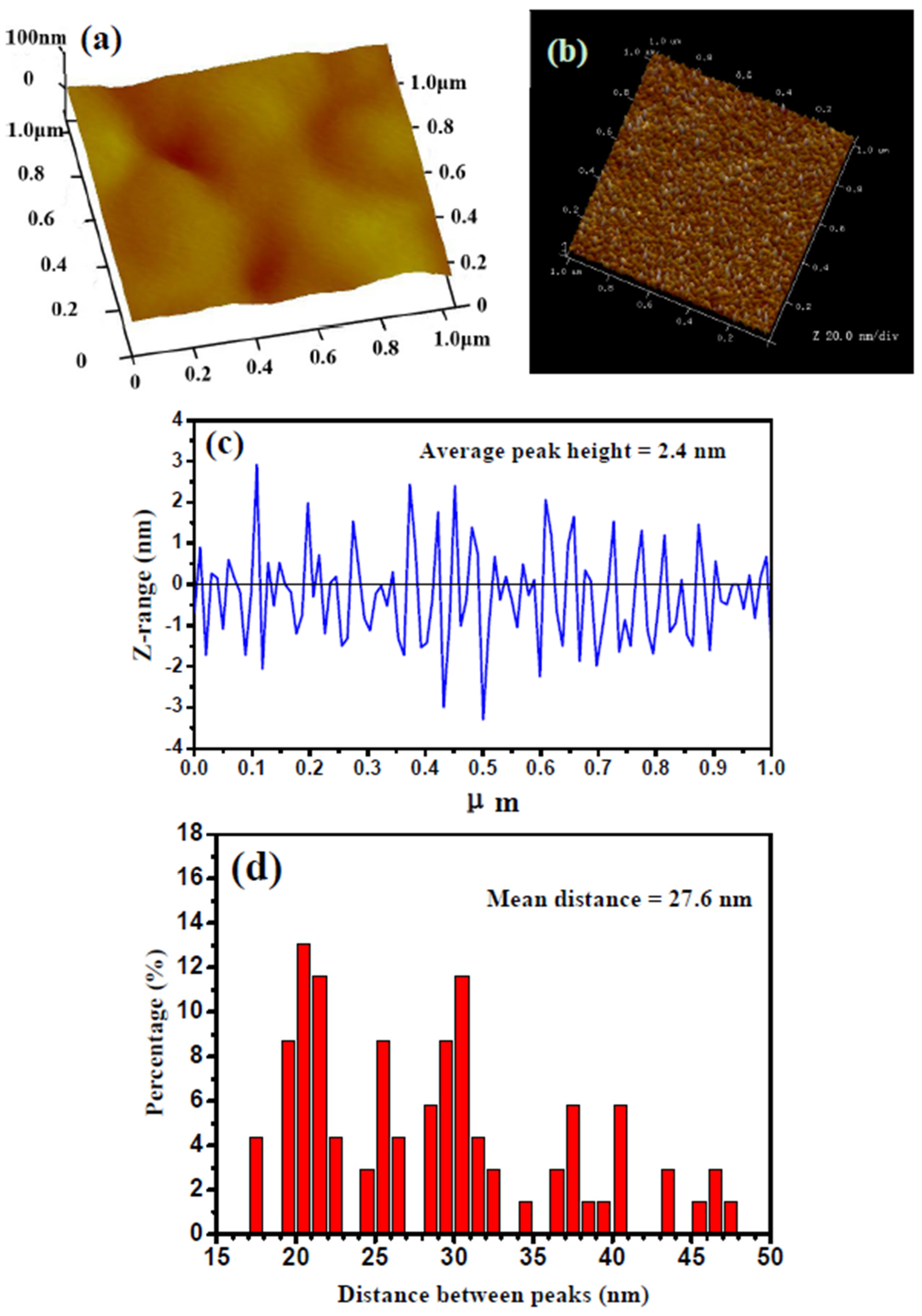
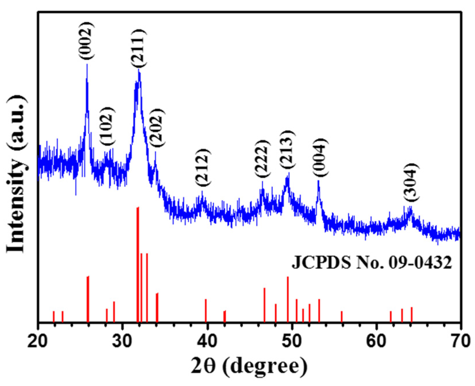
3.1. Crystalline Structure and Microstructure of Ta Coating

Figure 1 shows typical XRD pattern recorded from the Ta coating deposited onto a Ti-6Al-4V substrate. The coating shows three peaks located at 33.7°, 37.9° and 70.8°, assigned to the (002), (202) and (004) lattice planes of the tetragonal β-Ta crystal (JCPDS 25-1280), respectively. Additionally, the most intense reflection, (002), shows significantly higher intensity than that of the corresponding standard powder diffraction pattern that indicates that the coating grows predominantly with a (002) orientation. The presence of the (002) texture is frequently observed on β-Ta coatings prepared by the other sputter deposition techniques [21,22]. The average grain size of the coating was estimated to be ~18 nm by applying the Scherrer formula for peak broadening of the low angle (002) reflection, after the correction of instrumental line broadening [23].
Figure 2a,b displays representative three-dimensional AFM images of the surface morphology of the polished Ti-6Al-4V alloy and the as-deposited Ta coating, respectively. The polished Ti-6Al-4V alloy has a smooth surface and a surface roughness (Ra) of 1.2 nm. In contrast, small tapered nanoscale nodules are distributed on the coating surface uniformly and the surface roughness of the β-Ta coating, Ra is ~4.1 nm. The line profile for the coating obtained from the AFM section analysis and the statistical analysis for the distribution of peak distances are presented in Figure 2c,d, respectively. The average peak height is 2.4 nm, and the peak distance distribution ranges from 15 nm to 55 nm with an average value of 27.6 nm, as shown by the histogram in Figure 2d. As noted, the surface structure in the nanometer scale can play an important role in in vitro bioactivity for the as-deposited β-Ta coating.
Figure 3a shows a typical SEM cross-sectional image of the β-Ta coating deposited on the Ti-6Al-4V substrate. From the cross-sectional morphology in Figure 3a, the β-Ta coating, with a uniform thickness of ~40 µm, exhibits a homogeneous and continuous microstructure and appears well bonded to the substrate. No defects, such as pinholes, macro-droplets or microcracks, are visible either within the coating cross-section or at the coating-substrate interface. Such a dense structure is beneficial to the hindrance of inward diffusion of corrosive species into the underlying substrate.
A typical plan-view TEM bright-field image obtained from the β-Ta coating is shown Figure 3b, together with corresponding selected area electron diffraction (SAED) pattern. TEM observations indicate that the microstructure of the β-Ta coating consists of equiaxed nanoscale grains separated by large-angle grain boundaries with an average grain size ~22 nm. It should be noted that the TEM grain size is slightly larger than the XRD grain size, due to the presence of structural defects (i.e., stacking faults or low-angle grain boundaries) and the disordered character of grain boundaries [24]. An intense β-Ta (002) ring in the inset selected area diffraction pattern in Figure 3b provides further evidence that the β-Ta coating has a strong (002) texture, in excellent agreement with the XRD results. Numerous lattice fringes can be observed in the high-resolution TEM (HRTEM) image shown in Figure 3c for the β-Ta coating, and a number of individual β-Ta nanocrystals with strong (002) crystal planes can be resolved.

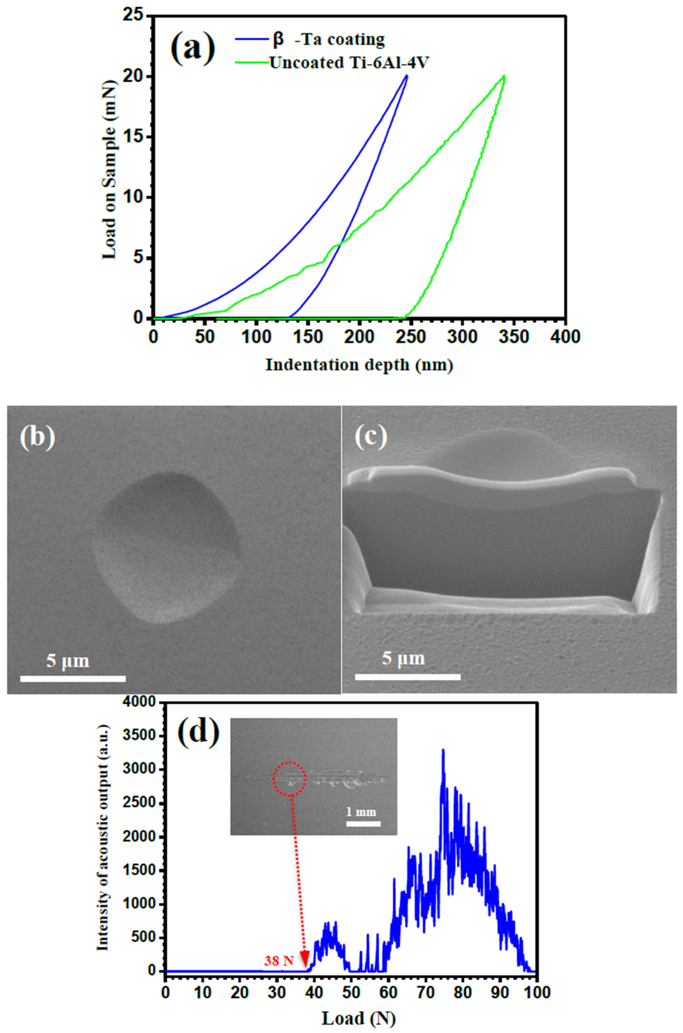
3.2. Nanoindentation and Scratch Tests

Figure 4a shows the representative load–displacement (Ph) curves of the β-Ta coating and uncoated Ti-6Al-4V measured using a nanoindentation tester equipped with a Berkovich indentor under a maximum load of 20 mN. Under the same load, compared to uncoated Ti-6A1-4V, the β-Ta coating undergoes less plastic deformation, as evidenced by a lower maximum indentation depth and residual depth. In other words, Ti-6A1-4V coated with the β-Ta exhibits a greater resistance to local plastic deformation. From more than 10 indentations, the average hardness and elastic modulus, respectively, were increased from 5.7 GPa and 137.5 GPa for uncoated Ti-6Al-4V to 17.1 GPa and 245.4 GPa for the β-Ta coating. It should be noted that the maximum indentation depth is far less than 10% of the coating thickness, suggesting that the contribution to the measured mechanical properties from the substrate is likely to be negligible. The hardness value of the β-Ta coating is consistent with the results reported elsewhere in the literature for β-Ta coatings, which are typically in the range of 15 to 23 GPa, depending on microstructural features such as grain size and grain orientation [25]. Because the complicated four layer stacking fault arrangements on (002) plane of β-Ta, dislocations are less mobile for β-Ta coatings when they exhibit a strong (002) texture. As is well known, the grain size dependence of hardness for polycrystalline metals can be described by the classical Hall–Petch relationship. The hardness value changes from 15 GPa for the β-Ta film with a grain size of 32.3 nm [25] to 16–23 GPa for the β-Ta films with grain sizes in range of 5−15 nm [26]. According to the Archard’s theory [27], the wear resistance is proportional to the hardness of the material. Consequently, it is expected that the wear resistance of Ti-6Al-4V can be significantly enhanced by the use of a β-Ta coating.
α-Ta is usually preferred to β-Ta in applications where coatings are subjected to both chemical attack and wear because β-Ta is believed to be more brittle than α-Ta, and its presence compromises coating integrity under external loads. To explore the contact damage resistance of the β-Ta coating, a cross-section through an indentation on the coating was prepared by FIB microscopy. Figure 4b,c shows surface and FIB cross-sectional images of an indent on the β-Ta coating subjected to a load of 500 mN, respectively. No evidence of crack formation or propagation is detectable on the coating surface or in the cross-section. A large number of simulations and experimental observations have indicated that the grain boundary-mediated process including grain boundary sliding and grain boundary rotation is the primary deformation mechanism in nanocrystalline materials with grain sizes <50 nm [28,29], and this can enhance the toughness of nanocrystalline brittle materials, such as intermetallics and ceramics [30]. Therefore, the grain boundary-mediated plasticity is beneficial to the improved ductility of the β-Ta coating.
The adhesion strength of the β-Ta coating to Ti-6Al-4V substrate is one of the most important factors for determining the lifetime service of coating/substrate systems following implantation. The critical load (Lc) from a scratch test was assessed by a scratch tester equipped with an acoustic emission detector, with the help of scratch morphology observation. The acoustic emission signals are plotted as a function of the normal load in Figure 4d. Apparently, no acoustic emission signals were observed at the early stage of scratching, and up to a scratching load of 38 N a continuous acoustic emission occurred. As shown in the inset of Figure 4d, at scratching loads below 38 N, the scratch track is characterized by numerous plowing grooves along the sliding direction, without the appearance of cracks and delamination, while at scratching loads above 38 N, the large-scale and continuous delamination at the edge of the scratch track is observed. The critical load value for the β-Ta coating is higher than that for a β-Ta film prepared on Co-Cr alloy with a similar method (18 N) [31] and that of wide acceptance for engineering applications (30 N) [32]. Therefore, the β-Ta coating adheres to the Ti-6A1-4V substrate sufficiently well to meet load-bearing applications in the human body.

3.3. Electrochemical Measurements

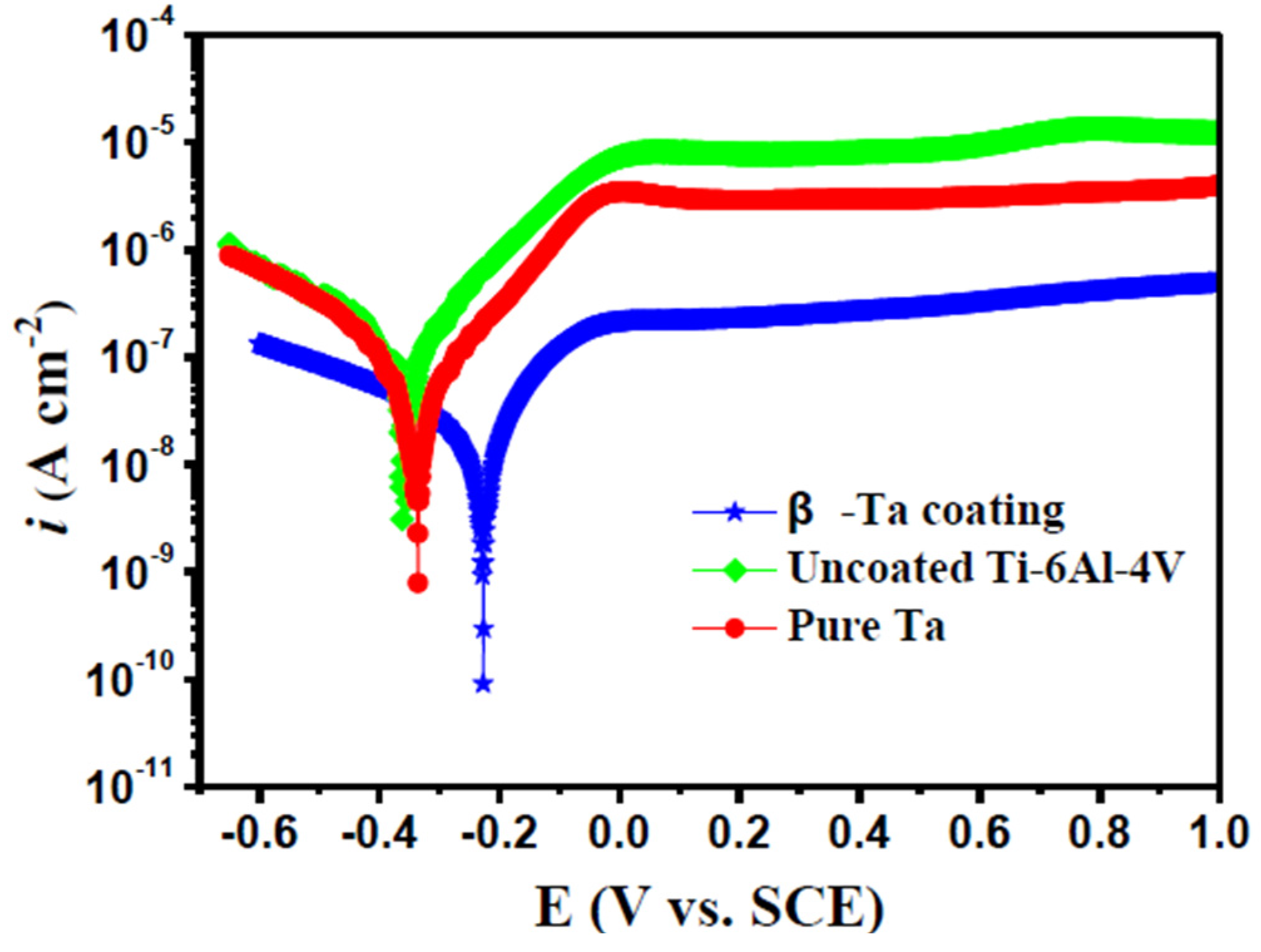
3.3.1. Potentiodynamic Polarization Tests

The potentiodynamic polarization curves of the β-Ta coating, uncoated Ti-6Al-4V and commercially pure Ta in Hank’s solution at 37 °C are displayed in Figure 5. The anodic polarization curves of tested samples are spontaneously passivated in the solution, with the low current density over a wide passive region in the anodic branch. Compared with the reference bare Ti-6Al-4V alloy and commercially pure Ta, the polarization curve of the β-Ta coating shifts toward a positive direction and simultaneously toward the region of lower current density, indicating that the β-Ta coating exhibits a lower electrochemical active behavior, reducing both the anodic and cathodic reactions. Generally, the more positive Ecorr of the β-Ta coating implies a higher chemical stability, while the smaller anodic current density reflects the lower corrosion rate and metal ions released into human body fluids. Moreover, the polarization resistance (Rp) is normally proportional to the corrosion resistance of material. Corrosion kinetic parameters, such as the corrosion potential (Ecorr), the corrosion current density (icorr) and polarization resistance (Rp) are summarized in Table 1 to evaluate the corrosion resistance of the samples, where Rp is derived from the Stern-Geary Equation as described in [33]. In Table 1, the corrosion resistance of the β-Ta coating is superior to both commercially pure Ta and uncoated Ti-6Al-4V, as indicated by the lowest icorr and highest Ecorr and Rp amongst the three tested samples.

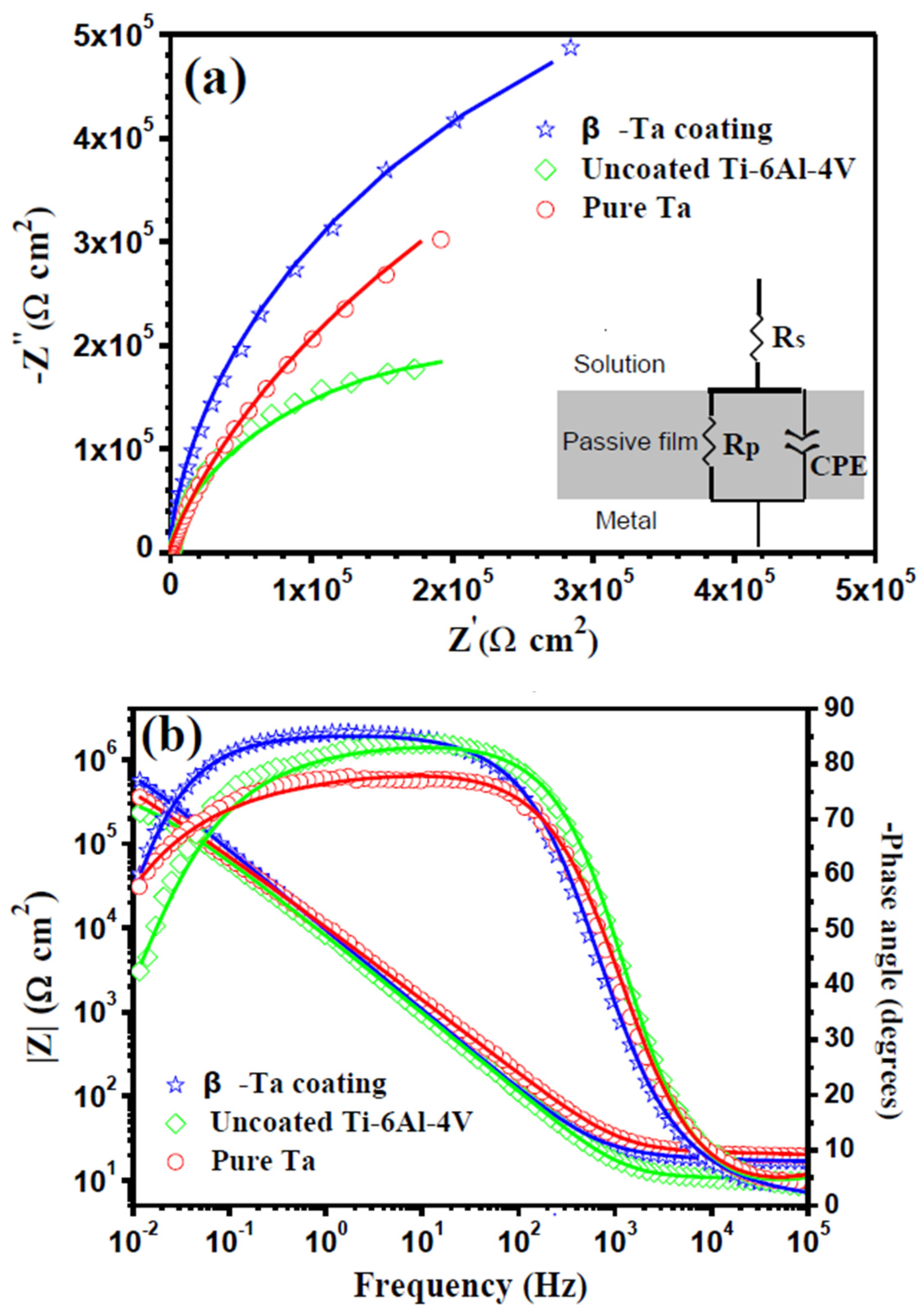
3.3.2. Electrochemical Impedance Spectroscopy (EIS)

Figure 6 shows impedance spectra, in the form of Nyquist and Bode plots, of the β-Ta coating, uncoated Ti-6Al-4V and commercially pure Ta at respective open circuit potential in Hank’s solution at 37 °C. It can be observed from Figure 6a that the impedance response of the tested samples in the Nyquist complex plane is essentially incomplete capacitive loop in the whole frequency range. The diameter of the semi-circle of the capacitive loop of the β-Ta coating is much larger than those of the two reference samples, indicating that it has a highest electrochemical resistance amongst the three test samples. From the Bode plots (Figure 6b), in the higher frequency, log|Z| tends to become constant, with the phase angle values falling rapidly towards 0° with increasing frequency. This is a response typical of the resistive behavior, corresponding to the solution resistance. In the broad middle and low frequency range, linear dependence of log|Z| on log f with a slope approximating −1 and phase angle maximum plateau near 90° spanning about three frequency decades represent predominately the characteristic response of a capacitive behavior. Compared with uncoated Ti-6Al-4V and commercially pure Ta, the β-Ta coating exhibits wider frequency region for the linear relationship of log|Z| to log f and for the phase angle maximum plateau, denoting that the passive film formed on the β-Ta coating is more insulating and protective than those for the two reference samples. This is in agreement with the results obtained from the potentiodynamic polarization measurements. Within the frequency range studied, the Nyquist plots for the three samples exhibit only one time constant, indicating that the interface between the tested samples and electrolyte could be modeled by a polarization resistance Rp and a constant phase element (CPE) in parallel, both of which are connected in series with an electrolyte resistance Rs, as shown in the inset in Figure 6a. In this circuit, to get a better fit, a more general constant phase element (CPE) was employed instead of a capacitive element. The impedance of a CPE is defined as:
Z CPE = 1 Q ( j ω ) n
where Q is the frequency independent parameter (Ω−1 cm−2·sn), j is the imaginary number, ω is the angular frequency (rad·s−1) and n is an adjustable parameter that usually lies between 0.5 and 1.0. As shown in Figure 6, the simulated results (shown as solid lines) match the experimental data (shown as individual points) well with the chi-squared (χ2) values being of the order of 103~104, signifying that the proposed equivalent circuit reasonably reflects the actual electrochemical process occurring on the tested samples in Hank’s solution at 37 °C. The simulated circuit elements are shown in Table 2. In Table 2, the Rp value of the β-Ta coating is the largest (1.34 × 10⁶ Ω·cm2) in comparison with the two reference samples, confirming the highest stability of the β-Ta coating in Hank’s solution. In addition, the time constant (τ), which is inversely proportional to the rate of the relevant electrochemical process, including the ionic migration within the oxide film and charge transfer, can be defined by τ = Rp × Cp, where Cp is the effective capacitance converted from Qp based on the criteria formulated by Brug et al. [34]:
C p = Q p 1 / n ( R s 1 + R p 1 ) ( n 1 ) / n
As shown in Table 2, the τ value of β-Ta coating is 15.33 s, much greater than those of uncoated Ti-6Al-4V (4.32 s) and commercially pure Ta (5.53 s), indicating that β-Ta coating has the lowest corrosion rate.

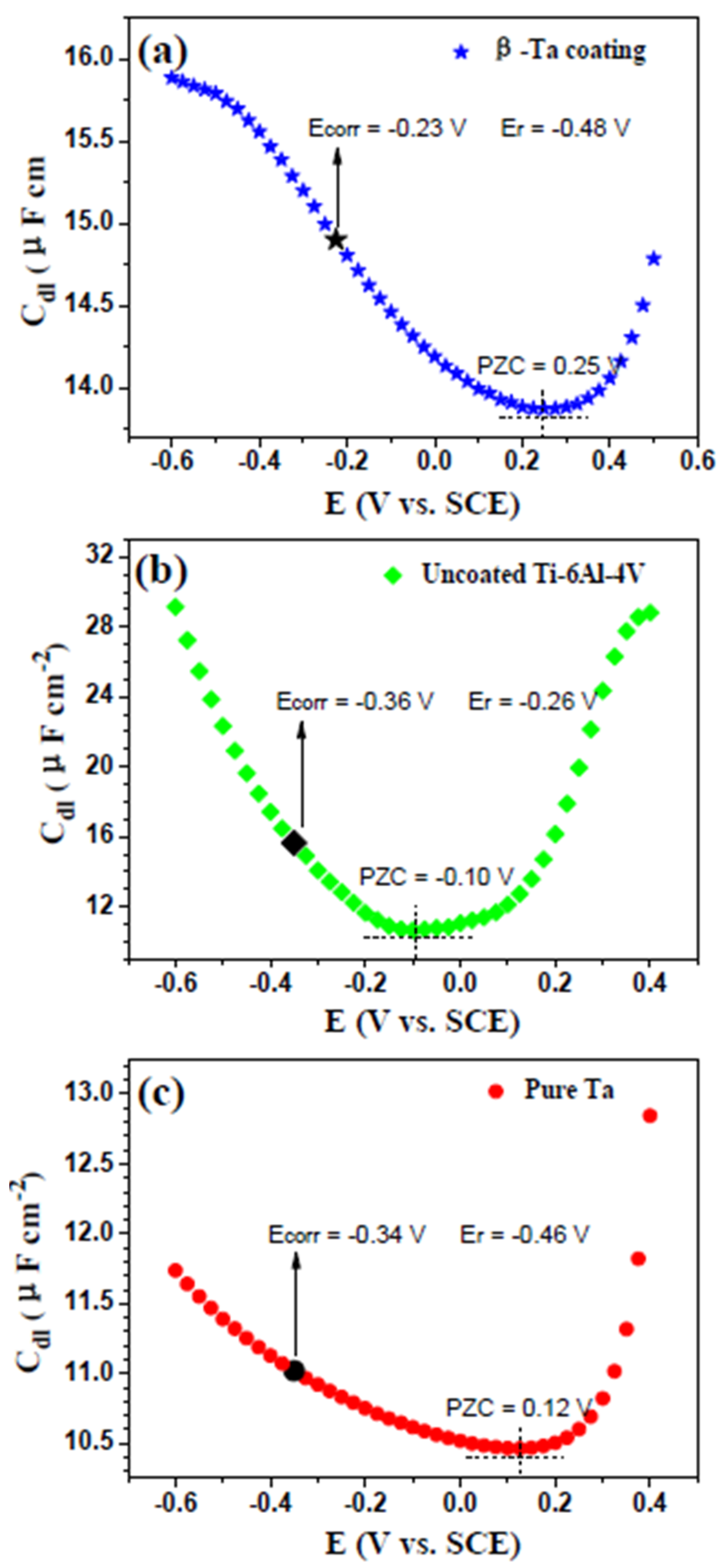
3.3.3. PZC Measurements

Because body fluid is a complicated electrolyte containing various inorganic ions and organic substances, the electrically charged surface of an artificial implant derived from the electric field existing at the implant/solution interface could have an impact not only on its corrosion behavior due to the surface adsorption of aggressive chloride ions, but also on its biological response (e.g., apatite induction, cell adhesion, proliferation and differentiation) [35,36]. The surface charge can be defined by the position of the corrosion potential Ecorr in respect to the respective potential of zero charge (PZC). When the difference, ∆E (∆E = EcorrEPZC), is negative, the electrode surface acquires a negative net charge and the adsorption of cations is favored. On the contrary, the adsorption of anions is favored when ∆E becomes positive [37]. According to the Gouy-Chapman theory [38], PZC is commonly defined as the potential corresponding to a minimum double layer capacitance in the CdlE curve. Figure 7 shows the double layer capacitance of the three tested samples in Hank’s solution at 37 °C as a function of applied potential. As shown in Figure 7, the PZC values for the β-Ta coating, uncoated Ti-6Al-4V and commercially pure Ta are, respectively, 0.25, −0.10, and 0.12 V, all of which are more positive than their respective Ecorr, implying that the surfaces of the test samples are negatively charged at their Ecorr. As a consequence, the negative charge of the three tested samples may be more appropriate for the electrostatic adsorption of cations, rather than aggressive Cl anion. According to the values of ∆E, it is concluded that the capability to repulse anions or to adsorb cations increases in the order of uncoated Ti-6Al-4V < commercially pure Ta < β-Ta coating.

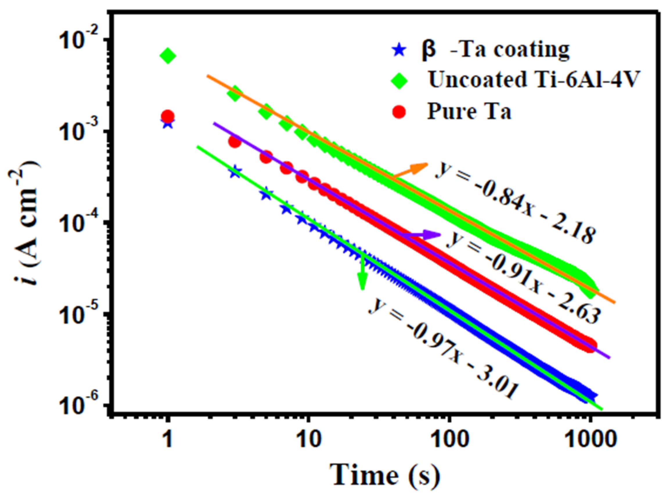
3.3.4. Potentiostatic Polarization Tests

One key factor that influences the stability of the passive layer is its compactness, which can be assessed by potentiostatic polarization analysis. A higher compactness imparts the passive film with a greater protective ability to obstruct the permeation of aggressive ions into the film [39]. After cathodic reduction, the variation of current with time for each specimen was measured at a fixed potential. If we neglect the contribution of the double layer charge, the initial fall of current density should be related to a film growth on the electrode surface [40]. The film growth kinetics fit the formula below [41]:
i = 10 ( A + k lg t )
where A is a constant depending on the applied potential and electrolyte character, and k represents the slope of the double-log plot for potentiostatic polarization. k = −1 usually signifies the formation of a compact and highly protective passive film, while k = −0.5 indicates the presence of a porous and diffusion-controlled film. Figure 8 presents the double-log plots of current density versus polarization time for the β-Ta coating, uncoated Ti-6Al-4V and commercially pure Ta potentiostatically polarized at 0.8 V in Hank’s solution at 37 °C. The values of k for the passive films grown on the β-Ta coating, uncoated Ti-6Al-4V and commercially pure Ta are −0.97, −0.84 and −0.91, respectively. This result indicates that the compact property of the passive film on the β-Ta coating is noticeably higher than those of uncoated Ti-6Al-4V and commercially pure Ta.

3.3.5. Mott-Schottky Analysis

In general, the formation and breakdown of the protective passive films on implanted materials depend largely on electronic and ionic transport processes, which are, in part, determined by their electronic properties [42]. A detailed perception of the electronic properties of the passive film is vital to gain insight into the operating corrosion mechanisms of the investigated samples. The semiconducting parameters of the passive film on metal are often acquired using the Mott-Schottky analysis based on the measurement of the electrode capacitance as a function of the applied potential. The reciprocal of the square of the capacitance (Csc) and the applied potential (E) exhibited a linear relationship under the depletion conditions. The basic equation for Mott-Schottky analysis is listed as follows [43]:
1 C sc 2 = 2 ε r ε 0 q N q ( E E f b k T q )
where εr is the dielectric constant of the passive film (~60 [44] for TiO2 and ~25 [45] for Ta2O5), ε0 is the vacuum permittivity (8.854 × 10⁻¹⁴ F·cm−1), q is the elementary charge (+e for electrons and −e for holes), Nq is the density of charge carriers (Nd for donors and Na for acceptors), E is the applied potential, Efb is the flat band potential, k is the Boltzmann constant (1.38 × 10⁻²³ J·K−1), and T is the absolute temperature (310 K).
Figure 9 presents the Mott-Schottky plots for the passive films formed on the β-Ta coating, uncoated Ti-6Al-4V and commercially pure Ta potentiostatically polarized at 0.8 V for 1 h in Hank’s solution at 37 °C. As shown in Figure 9, there is a break point that separates Mott-Schottky plots into two linear regions, and the two linear regions in each plot slopes show a positive slope, denoting the n-type semiconductive properties of the passive films formed on the investigated specimens. This result means that the dominant defects in all the passive films are oxygen vacancies and/or cation interstitials [46]. Such two linear regions at low and high potentials were reported to be attributed to the semiconducting behavior and dielectric character of the passive film, respectively [47]. In the present study, the linear region at low potential was chosen to calculate the semiconductor property parameters of the passive films formed on the tested samples. It is worth noting that there is a linear region with negative slope observed on the Mott-Schottky plot of commercially pure Ta, which is related to the formation of an inversion layer as a result of an increasing hole concentration in the valence band, as discussed elsewhere [48].
Based on the above analysis, the corresponding semiconducting parameters for the passive films formed on the three investigated specimens are given in Table 3. It is clear that the donor density (Nd) of the passive film formed on uncoated Ti-6Al-4V (2.45 × 1019 cm−3) is comparable to that of commercially pure Ta (2.46 × 1019 cm−3), both of which are approximately three times higher than that of the β-Ta coating (8.70 × 1018 cm−3). Compared to the two reference samples, an appreciable reduction in the donor density of the β-Ta coating represents a significant decrease in the content of oxygen vacancies in its passive film. Oxygen vacancies are commonly considered as donor-type defects and contribute to an excess of electrons in the passive film, resulting in an increase of the electrical conductivity [49]. Therefore, the higher Nd means the higher conductivity of the passive film, thus promoting mass transport of ions across the passive film. In addition, owing to the existence of certain amount of chloride ions in Hank’s physiological solution, aggressive chloride ions can be transferred through the film/solution interface and preferentially occupy oxygen vacancies in n-type semiconducting passive films on the samples, decreasing the concentration of the oxygen vacancies in accordance with the following reaction [46]:
V O ¨ + Cl Cl O ˙
where Cl O ˙ represents a chloride ion absorbed into an oxygen vacancy, V O ¨ , in the passive film/electrolyte interface. This process is followed by a Schottky-pair type reaction:
Null V M χ + χ 2 V O ¨
where V M χ represents a cation vacancy. The newly generated oxygen vacancies can in turn react with additional chloride ions at the passive film/electrolyte interface to generate more oxygen and cation vacancies. Absorption of chloride ions into surface oxygen vacancies is an autocatalytic process, which leads to the generation of cation vacancies at the passive film/electrolyte interface and, hence, to an enhanced flux of cation vacancies across the passive film to the metal/passive film interface, where they are annihilated by the emission of cations from the metal into the passive film as follows:
m + V M χ M M + V m + χ e
where m is a metal atom, MM a metal ion in cation site of the passive film sublattice, and Vm a vacancy in metal phase. If this annihilation reaction is not capable of consuming the cation vacancies arriving at the metal/passive film interface, the excess cation vacancies will condense to form voids and finally cause the local detachment of the passive film from the underlying metal substrate. Because of their passive films with higher Nd values, uncoated Ti-6Al-4V and commercially pure Ta more readily absorb chloride ions than the β-Ta coating, resulting in the less chemically stable in physiological solution. Therefore, the passive film formed on the β-Ta coating exhibits lower conductivity and higher stability as compared to those formed on the two reference samples, endowing it higher corrosion protection capability in Hank’s physiological solution.
Often, the thickness of the space charge layer scales directly with that of the passive film. The thickness of the space charge layer (δsc) for an n-type semiconducting passive film can be calculated from Equation (8) [44]:
δ sc = [ 2 ε r ε 0 e N d ( E E f b k T e ) ] 1 / 2
In Table 3, the passive film formed on β-Ta coating possesses the largest δsc (27.37 nm), followed by uncoated Ti-6Al-4V (20.74 nm) and then commercially pure Ta (15.86 nm). A thicker passive film is expected to have less structural defects than a thinner passive film, and would be less prone to dielectric breakdown [50].

3.4. Apatite-Forming Ability

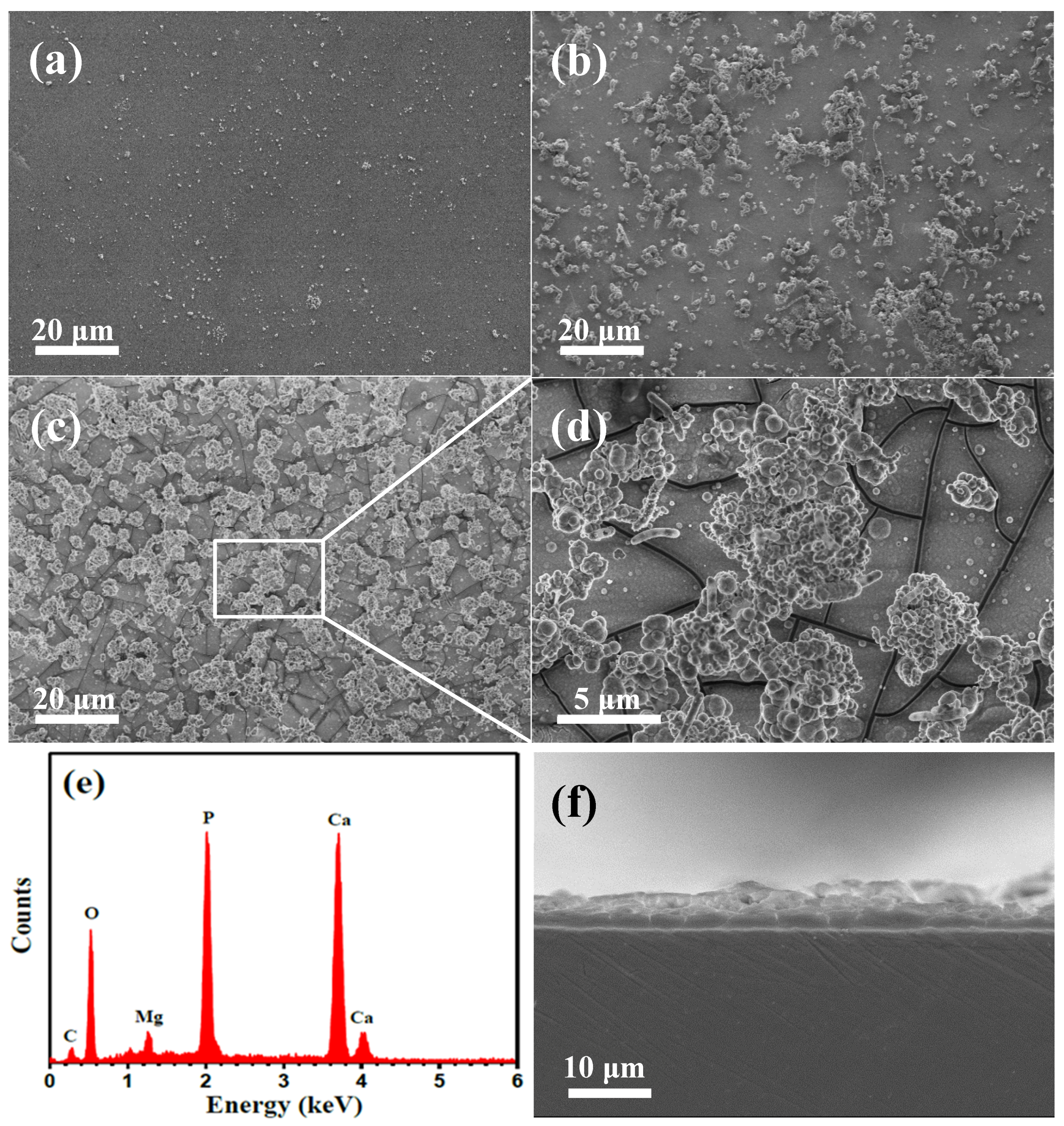
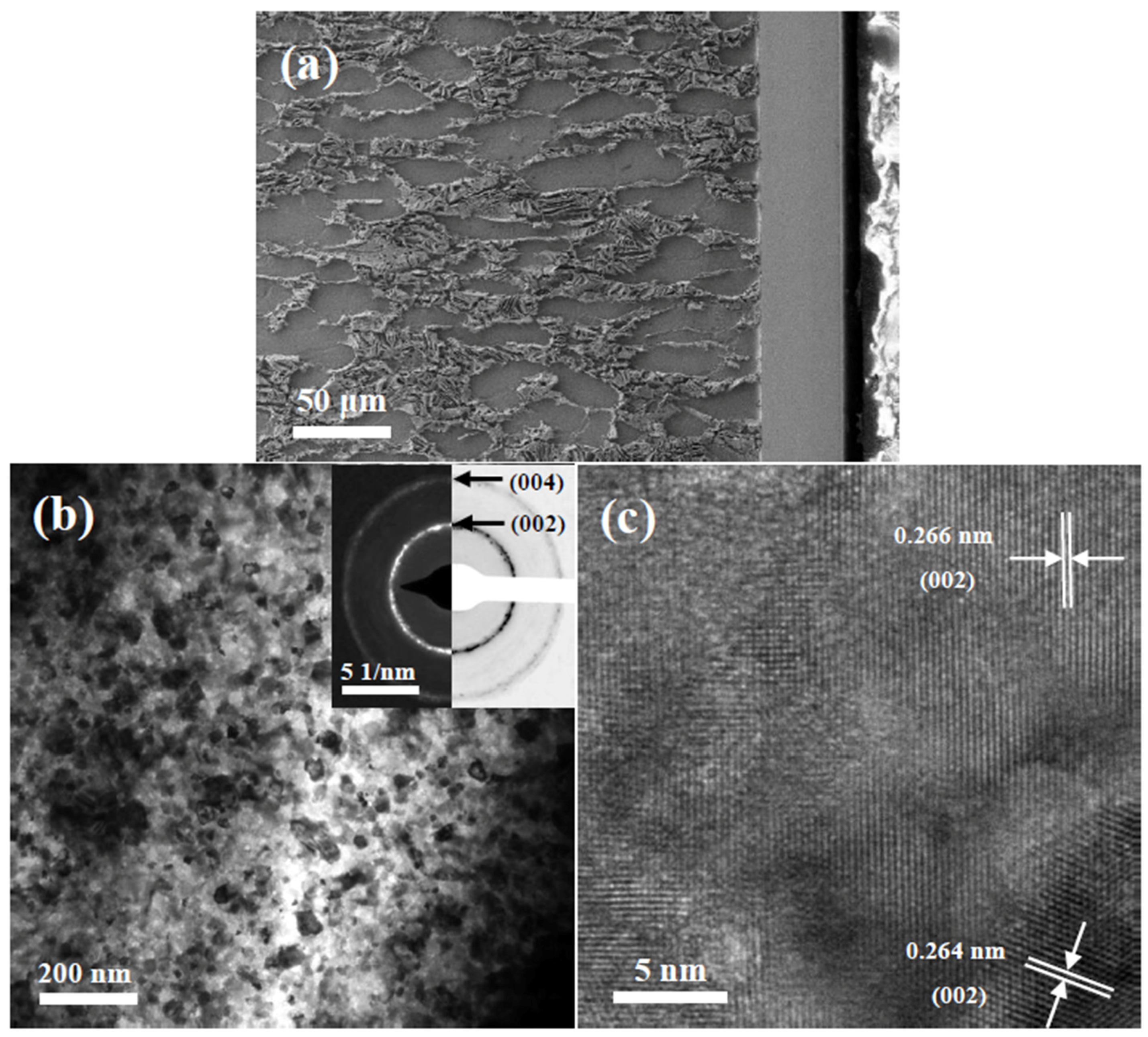
3.4.1. SEM Observation
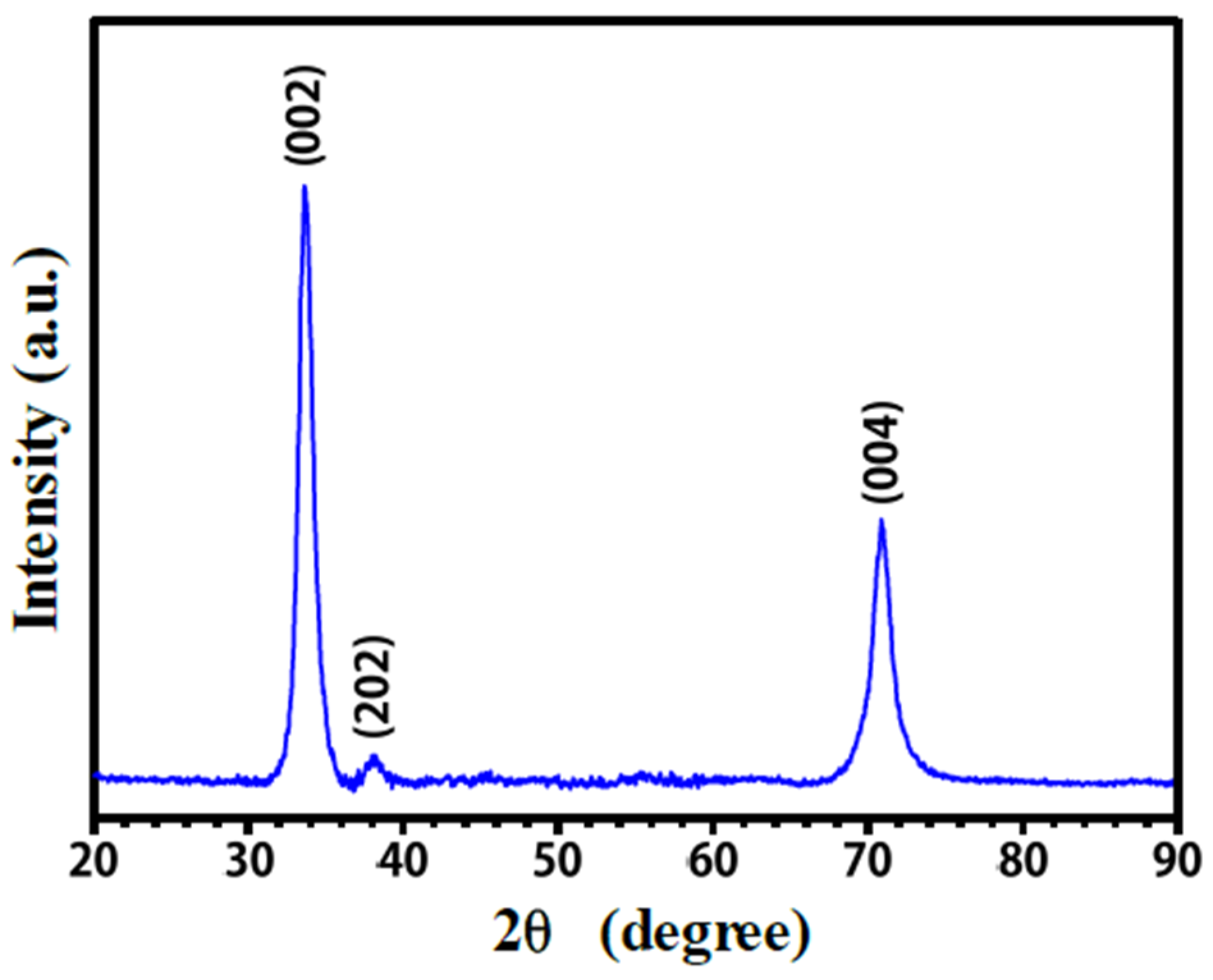
As one important property of orthopedic implants in bone fracture healing, the apatite-forming ability of the surface of the implants in SBF solution in vitro has been widely assumed to be a predictor of bioactivity in vivo [51]. Figure 10a–c shows typical SEM images of the surface morphologies of uncoated Ti-6Al-4V, commercially pure Ta and the β-Ta coating after seven days of immersion in Hank’s solution, respectively. It is clearly visible that there is a notable difference in kinetics of apatite layers grown on different samples confirmed by the morphological differences between them through the SEM observations. As shown in Figure 10a, the surface morphology of uncoated Ti-6Al-4V remains almost unchanged, with only limited numbers of granular particles randomly dispersed over the surface. Compared with uncoated Ti-6Al-4V, more surface areas of commercially pure Ta (Figure 10b) are covered by some clustered island-like particles with a coverage of ~38.6%, no sign of formation of a continuous apatite film. In contrast, numerous micron-sized grayish clusters, with irregular shapes, are observed on the β-Ta coating (Figure 10c). At higher magnification (Figure 10d), it can be observed that that the grayish clusters are actually composed of many spherical particles, and beneath those clusters, a smooth and uniform apatite layer with many large microcracks is formed on the surface of the β-Ta coating. The above results suggest that during the biomimetic apatite deposition process, the grayish clusters nucleate and precipitate in the initially formed apatite layer, reflecting that the β-Ta coating exhibits good apatite-inducing ability. Similar morphological features of apatite layer have been previously observed by other researchers [52,53]. In addition, those microcracks were formed due to tensile stresses build up during the drying process, originating from the thermal expansion difference between the β-Ta coating and the apatite layer. The EDS spectra (Figure 10e) from the apatite layer formed on the surface of the β-Ta coating indicates the presence of Ca, P, O, and a small fraction of Mg and C. The apatite layer has a Ca/P atomic ratio of 1.52, deviating only slightly from the stoichiometry of hydroxyapatite (HA, Ca10(PO4)6(OH)2) value of 1.67. This may be related to the calcium-deficient apatite because of the presence of various random substitutions at the HA lattice sites by trace components, for example, substitution of Mg2+ for Ca2+ or CO32− and Cl occupying PO43− and/or OH sites [54,55]. A SEM cross-sectional image of the apatite layer grown on the β-Ta coating after seven days of exposure to Hank’s solution is shown in Figure 10f. It can be seen from this image that a compact apatite layer with a thickness of 3~5 μm is tightly bonding to the β-Ta coating. These findings reveal that the β-Ta coating shows a higher apatite-forming ability than bare Ti-6Al-4V and commercially pure Ta.

3.4.2. XRD Analysis

Figure 11 shows the typical XRD pattern of β-Ta coating after immersion in Hank’s solution for seven days. For comparison, data from the JCPDS card (No. 09-0432) for standard hydroxyapatite is also included in this figure (represented by vertical red lines). As can be observed, all the recorded peaks can be well indexed to hexagonal hydroxyapatite, and no peaks are detected stemming from underlying β-Ta coating, confirming that the β-Ta coating is covered completely with a thick apatite layer. The XRD pattern of the biomimetic apatite layer displays broad peaks with relatively low intensity, indicating that the apatite crystal sizes are very small and/or a low degree of crystallinity. Furthermore, two principal reflections, (002) and (211), have a ratio of the relative strength of I(002)/I(211) of about 1, which is higher than that of the standard apatite powder XRD pattern (0.4). This meant that the apatite layer formed on the β-Ta coating shows a preference along the crystal orientation of [001], which is generally found in bone and calcified tendon [56].

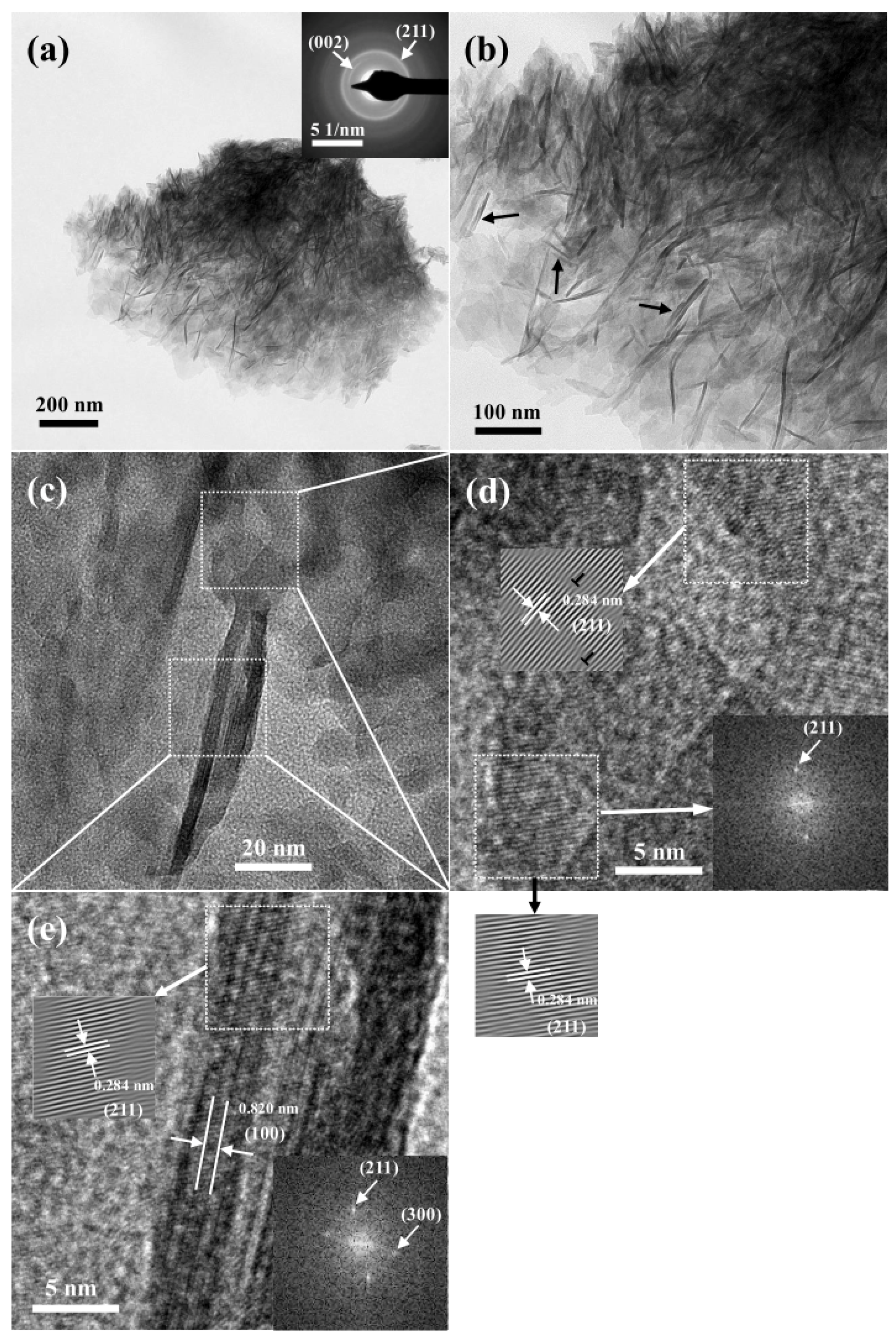
3.4.3. TEM Observation

Figure 12 shows bright-field TEM and HRTEM images of the precipitated apatite on the β-Ta coating after soaking in Hank’s solution for seven days. As seen in Figure 12a, the precipitated apatite is composed of numerous needle shape crystallites developed to form aggregates. The SAED pattern (inset in Figure 12a) exhibits two strong rings corresponding to (002) and (211) planes of apatite, which is in good agreement with the XRD results. Notably, the (002) diffraction ring appears as two symmetric arcs, further confirming that the apatite crystal exhibits a preferred alignment with the (002) reflection. The apatite crystal tends to grow along the <001> direction leading to its needle-like morphology. The higher magnification TEM image (Figure 12b) reveals that those needle-like crystals are in the range of 50–168 nm in length and 4.0–6.9 nm in diameter, and several needle-like crystals are parallel to each other (marked with arrows), which was previously observed by Luong et al. [57]. The large variation in the length is derived from the difference in the nucleation and growth behavior for those needle-like crystals during the soaking process. As shown in Figure 12c, the contrast of two parallel needle-like apatite crystals is dark compared to the gray surrounding region, suggesting they are likely apatite crystals with different orientations and some amorphous phase. Figure 12d shows a HRTEM lattice image of the region adjacent to the root of the needle-like apatite crystals (marked with selected squares). The predominant precipitates in this region are identified as the lattice spacing of 0.284 nm corresponding to the (211) lattice plane of apatite crystals. Moreover, some edge dislocations are observed, presumably due to the presence of these structural defects arising from substitutions at the HA lattice sites by ions [58]. A HRTEM image (Figure 12e) of the needle-like crystals reveals that the lattice fringes of (100) plane of apatite crystals align in the direction of the long axis of each needle, with a interplanar spacing of 0.820 nm, indicating that the longitudinal direction of each needle is parallel to the c axis ((002) plane direction) of the hexagonal structured HA and its transverse direction is parallel to the (100) direction. For apatite-type crystals, the (100) face was more stable than the (101) and (001) faces, and the crystal was elongated predominantly in the <001> direction with the growth of (101) and (001) faces inhibited [59].

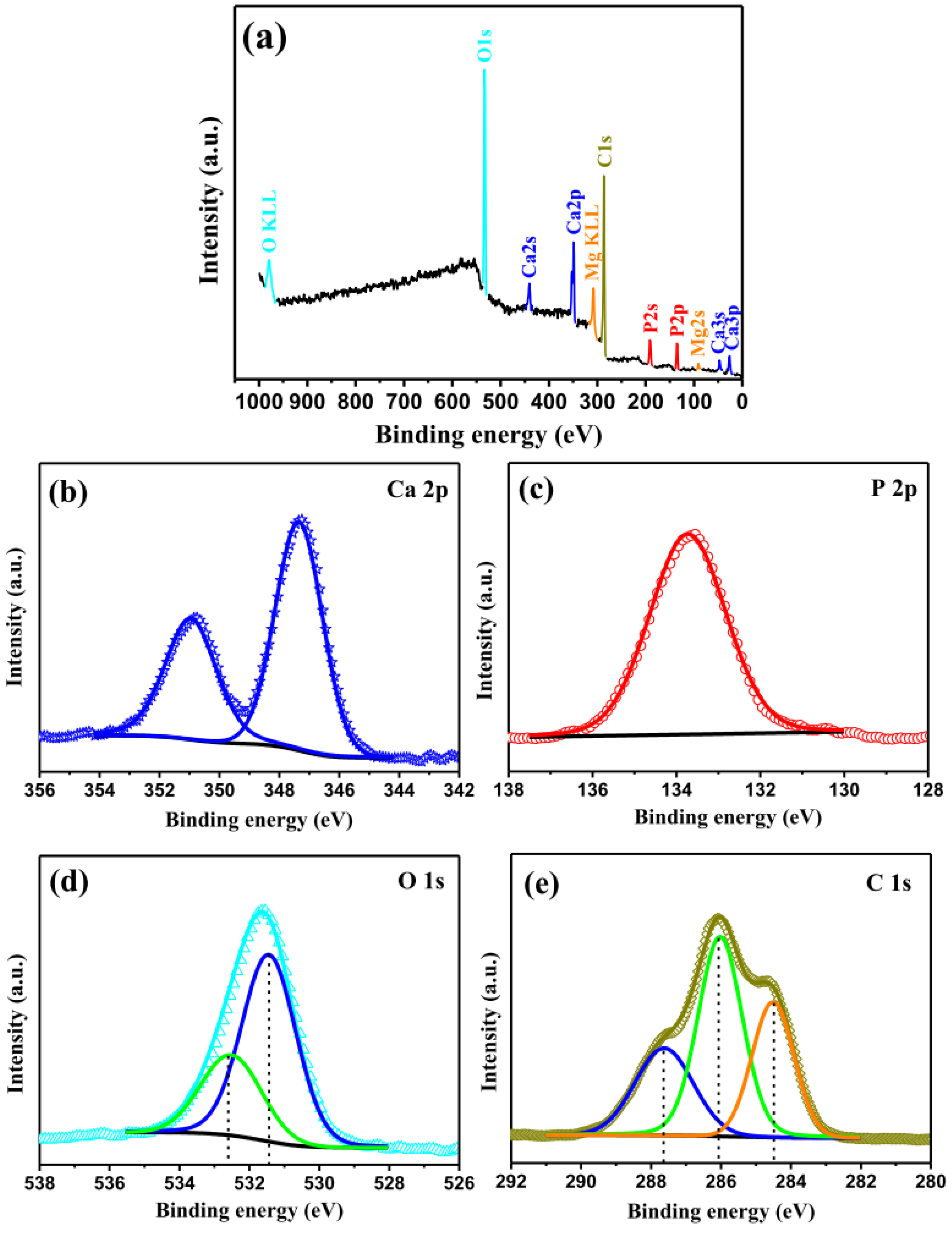
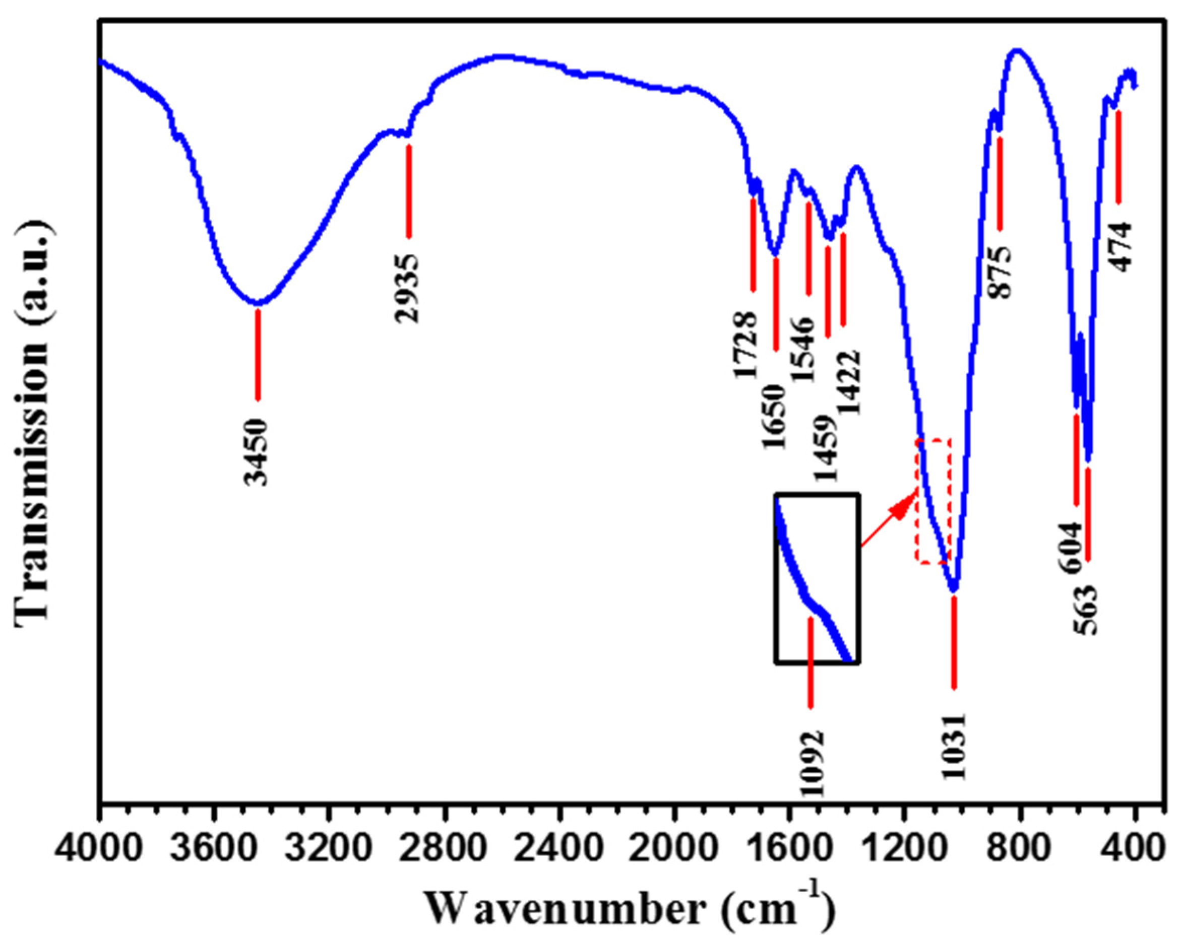
3.4.4. XPS and FT-IR Analysis

As shown in Figure 13a, XPS wide-scan survey spectrum indicates that oxygen, calcium, magnesium, carbon and phosphorus elements are present on the surface of the β-Ta coating after immersion in Hank’s solution for seven days, consistent with the EDS results. Figure 13b–e presents the core level spectra of Ca 2p, P 2p, O 1s and C 1s orbitals recorded from the surface of the β-Ta coating after immersion in Hank’s solution for seven days. In Figure 13b, the Ca 2p spectrum exhibits a doublet with Ca 2p3/2 and Ca 2p1/2 at 347.3 and 351.0 eV, respectively, corresponding to a divalent oxidation state (Ca2+) in inorganic calcium oxygen compounds [52]. In Figure 13c, the P 2p spectrum shows a single symmetric peak at 133.8 eV corresponding to a pentavalent oxidation state (P5+) [52]. The O 1s spectrum in Figure 13d appears a broad asymmetry peak, which can be deconvoluted into two peaks. An intense peak at 531.3 eV is assigned to the combined contribution of OH, PO43− and CO32− groups, which are inseparable by peak-fitting routine due to their similar binding energies [60,61]. The minor peak at 532.7 eV is attributed to the adsorbed water or C- and O-containing contaminations [61,62]. The Ca 2p3/2, P 2p and O 1s located at, respectively, 347.3, 133.8 and 531.3 eV are consistent with the typical binding energies of hydroxyapatite. The deconvolution of the C 1s spectrum (Figure 13e) reveals that it was composed of three peaks. The components at binding energies of 284.6 and 286.1 eV, respectively, correspond to hydrocarbon and hydroxyl carbon, which exist on the surface layer due to adventitious contamination from the surrounding environment [63,64]. The component at the highest binding energy of 287.7 eV is characteristic of carbonate groups CO32− [63,65]. The presence of carbonate in the C 1s spectrum indicates that the precipitated layer on the β-Ta coating surface is carbonate-containing apatite (CHA), which will be further confirmed by the data obtained with FT-IR.
Figure 14 shows the FT-IR spectrum of the precipitated apatite layer on the surface of the β-Ta coating after immersion in Hank’s solution for seven days. As shown in Figure 14, two broad bands associated with the vibration of the water molecules adsorbed on the surface of the apatite layer can be detected, where one broad adsorption band locates between 3800 and 3000 cm−1 and another bending band appears at 1650 cm−1 [64]. The spectrum shows strong absorption bands around 900–1200 cm−1 and 450–700 cm−1, which are assigned to the stretching and bending vibration of phosphate (PO43−) groups [66]. The asymmetric stretching mode (ν3) of the PO43− are detected at 1092 cm−1 and 1031 cm−1, corresponding to the P–O vibration, while a characteristic double recorded at 563 and 604 cm−1 originate from the ν4 mode of O–P–O bending vibration in apatite. Also, the band at 474 cm−1 belongs to the O–P–O symmetric stretching mode (ν2) of the PO43− vibration. These phosphate characteristic bands indicate the arrangement of the polyhedrons PO43− in the structure of hydroxyapatite. The broad, relatively unresolved phosphate bands, rather than very sharp bands as observed in typical HA spectra [67], are indicative of poor crystallinity of biomimetically deposited apatite [68], which is in accordance with the XRD result (Figure 11). The bands located at 875, 1422 and 1459 cm−1 are assigned to the (CO32−) groups of B-type carbonated hydroxyapatite, suggesting that carbonate groups occupying at the phosphate sites in HA lattice [69,70]. A weak band at 1546 cm−1, associated with A-type carbonate substitution, was also observed [69,70]. In addition, there is no evidence of the characteristic bands of hydroxyl groups located at 3570 cm−1 and 632 cm−1, proving again the existence of A-type carbonate-containing hydroxyapatite. The low intensities of the carbonate bands compared with the phosphate bands indicate low carbonate content in the biomimetic apatite. Because carbonates are constituents of human bone mineral [71], the presence of low content of CO32− is expected to endow the biomimetically grown apatite layer with high in vivo bioactivity. The adsorption bands at 1728 and 2935 cm−1 are associated with stretching vibrations of C=O and C–H bonds, respectively, which result from adventitious contamination on the sample surface [72]. Based on the above results, it can be concluded that the apatite layer precipitated on the surface of the β-Ta coating after seven days of immersion in Hank’s solution is composed of poorly crystallized AB-type carbonated hydroxyapatite.

4. Discussion

As is well known, the corrosion characteristics of an implanted alloy in the physiological environment are greatly influenced by the passive film formed on the surface of the alloy and the presence of alloying elements. The structural changes in the passive film or the variation in the ionic or electrical conductivity of the passive film alter its resistance against corrosion. As confirmed by the results of potentiodynamic polarization and EIS measurements, the β-Ta coating possesses better corrosion resistance than uncoated Ti-6Al-4V and commercially pure Ta. The potentiostatic polarization tests and Mott-Schottky analysis suggest that the β-Ta coating exhibits higher stability than uncoated Ti-6Al-4V and commercially pure Ta in Hank’s physiological solution, due to its higher compactness and lower donor density (Nd). A higher corrosion resistance of the β-Ta coating is intimately connected with its nanoscale microstructure. Compared to the two reference coarse-grained samples, the β-Ta nanocrystalline coating has higher volume fraction of grain boundaries, which provide more short paths for alloy element diffusion and facilitate rapid formation of a thermodynamically stable passive layer [73]. Furthermore, previous studies indicated that the passive film formed on nanostructured materials has a lower carrier density [74], which is agreement with the results of the Mott-Schottky analysis. The stronger and more stable the passive film is formed on the surface of the β-Ta coating, the better corrosion resistance is provided to improve biocompatibility of Ti-6Al-4V by suppressing the release of metal ions.
It is obvious from the results described above that the β-Ta coating shows higher ability to induce bone-like apatite nucleation and growth on its surface as compared to uncoated Ti-6Al-4V and commercially pure Ta. The surface characteristics of a medical implant, such as the topography, surface charge and surface energy, play an essential part in apatite-forming ability. Since nano-grained materials have a larger ratio of surface to volume than the micro-grained materials, they possess larger surface energy and are more likely to adsorb molecules or ions onto their surfaces to reduce surface energy, thus stimulating apatite nucleation on their surface [75]. It can also be demonstrated that morphological features such as surface roughness and its topography are the key factor to induce bone-like apatite to precipitate on the surfaces of metallic implants in SBF. Chen et al. [76] had evaluated the apatite-forming ability of the alkali and heat-treated Ti, Zr, and TiZr alloy in simulated body fluid. The results suggested that surface roughness critically affected the apatite formation on the pretreated metallic samples. Peltola et al. [77] and Viitala et al. [78] further pointed out that nano-scale topographic features (surface peak height and peak distance distribution) gave more precise information about the apatite-forming ability than surface roughness, and they found that the peak distance distribution between 5 and 50 nm, together with a peak height ≥1 nm, was particularly suitable for the deposition of apatite. As shown in Figure 2, unlike conventional coarse-grained materials utilized for orthopedic implants that have a rather smooth surface at the nanoscale [79], the β-Ta nanocrystalline coating exhibits a nanoscale topographic feature with an average peak height of 2.4 nm and an average peak distance distribution between 15 and 55 nm. The β-Ta coating with such a specific surface topography has an advantage over the two reference coarse-grain materials in promoting apatite nucleation, because it has more surface area to interact and adsorb ions [80]. Since the complex process of apatite formation was assumed to be involved with an electrostatic interaction between the metal surface and specific ions in the fluid, the surface charge of an implant is the main driving force for apatite nucleation on the surface. The isoelectric point (IEP), defined as the pH at which the surface is electrically neutral, is often used to investigate the surface charges. When soaking in Hank’s physiological solution, the Ta2O5 and TiO2 oxide films grow spontaneously on the surfaces of Ta (β-Ta coating and commercially pure Ta) and Ti-6Al-4V, respectively. Isoelectric points of Ta2O5 and TiO2 were reported to be 3.3 [81] and 5.6~6.4 [82], respectively, which are less than the pH value of Hank’s physiological solution (pH = 7.4). Hence, the surfaces of three tested samples have a net negative charge, which are consistent with the results of PZC measurements. Compared with uncoated Ti-6Al-4V and commercially pure Ta, the β-Ta coating has a higher the PZC value and a lower value of isoelectric point, implying that the β-Ta coating shows stronger electrostatic charge accumulated Ca2+ on its surface accelerating bone like apatite nucleation in Hank’s physiological solution. The above studies suggest that the β-Ta coating is considered a promising candidate coating for improving the long-term stability of Ti-6Al-4V implants in the human system by enhancing their in vitro bioactivity and biocompatibility, which would widen its applications in orthopedic and dental implants.

5. Conclusions

In this work, a novel nanocrystalline β-Ta coating with a thickness of ~40 μm was prepared on a Ti-6Al-4V substrate by a double glow discharge plasma technique. Following microstructural and mechanical characterization, the electrochemical corrosion behavior and apatite-inducing ability of the β-Ta nanocrystalline coating were investigated in Hank’s solution at 37 °C. On the basis of the experimental results, the following conclusions were obtained:
(1) The β-Ta coating exhibits a homogeneous and dense microstructure with a unique nano-topography characterized by numerous tapered nano-protuberances. The microstructure of the β-Ta coating is composed of equiaxed β-Ta grains with an average grain size ~22 nm, showing a preferential (002) orientation. The β-Ta nanocrystalline coating shows high hardness, combined with good resistance to contact damage, thus favoring it for long-term load-bearing applications in the human body.
(2) The β-Ta coating exhibits a more positive Ecorr, larger Rp and lower icorr than commercially pure Ta and uncoated Ti-6Al-4V in Hank’s solution at 37 °C, suggesting that the β-Ta coating exhibited a higher corrosion resistance than uncoated Ti-6Al-4V and commercially pure Ta. The results of EIS measurements show that the values of capacitance semicircle, phase angle maximum, as well as the frequency range with the phase angle near −90° for the β-Ta coating is larger than those for uncoated Ti-6Al-4V and commercially pure Ta, confirming that the passive film formed on the β-Ta coating is more insulating and protective than those for two reference samples in Hank’s solution. Mott-Schottky analysis and PZC measurement indicate that the β-Ta coating exhibits lower carrier density and a larger capability that can inhibit the adsorption of aggressive chloride ions.
(3) The β-Ta coating shows better apatite-inducing ability compared to uncoated Ti-6Al-4V substrate and commercially pure Ta. A dense bone-like apatite layer with a thickness of 3~5 μm is able to deposit on the surface of the β-Ta coating within 1 week of soaking in Hank’s physiological solution, indicating that the bioactivity of Ti-6Al-4V can be improved by coating with β-Ta. The specific surface characteristics are believed to be the key factors that induce precipitation of apatite on the surface of the β-Ta coating. The β-Ta coating could be considered as a promising candidate to serve as bone-bonding biomaterials.

Acknowledgments

The authors acknowledge the financial support from the General Program of the National Nature Science Foundation of China under Grant No. 51374130 and No. 51675267, and Key Program of the National Natural Science Foundation of China under Grant No. 51635004. This work is also supported by Funding of Jiangsu Innovation Program for Graduate Education, the Fundamental Research Funds for the Central Universities (CXLX13-151).

Author Contributions

L.L. Liu and J. Xu conceived and designed the experiments; L.L. Liu performed the experiments; L.L. Liu and J. Xu analyzed the data; S. Jiang contributed reagents/materials/analysis tools; J. Xu wrote the paper.

Conflicts of Interest

The authors declare no conflict of interest.

References

  1. Long, M.; Rack, H.J. Titanium alloys in total joint replacement—A materials science perspective. Biomaterials 1998, 19, 1621–1639. [Google Scholar] [CrossRef]
  2. Geetha, M.; Singh, A.K.; Asokamani, R.; Gogia, A.K. Ti based biomaterials, the ultimate choice for orthopaedic implants—A review. Prog. Mater. Sci. 2009, 54, 397–425. [Google Scholar] [CrossRef]
  3. Nishiguchi, S.; Kato, H.; Fujita, H.; Oka, M.; Kim, H.-M.; Kokubo, T.; Nakamura, T. Titanium metals form directed bonding to bone after alkali and heat treatments. Biomaterials 2001, 22, 2525–2533. [Google Scholar] [CrossRef]
  4. Zaffe, D.; Bertoldi, C.; Consolo, U. Element release from titanium devices used in oral and maxillofacial surgery. Biomaterials 2003, 24, 1093–1099. [Google Scholar] [CrossRef]
  5. Hanawa, T. Metal ion release from metal implants. Mater. Sci. Eng. C 2004, 24, 745–752. [Google Scholar] [CrossRef]
  6. Sun, Z.L.; Wataha, J.C.; Hanks, C.T. Effects of metal ions on osteoblast-like cell metabolism and differentiation. J. Biomed. Mater. Res. 1997, 34, 29–37. [Google Scholar] [CrossRef]
  7. Paital, S.R.; Dahotre, N.B. Calcium phosphate coatings for bio-implant applications: Materials, performance factors, and methodologies. Mater. Sci. Eng. R 2009, 66, 1–70. [Google Scholar] [CrossRef]
  8. Jaffe, W.L.; Scott, D.F. Current concepts review—Total hip arthroplasty with hydroxyapatite-coated prostheses. J. Bone Jt. Surg. Am. 1996, 78, 1918–1934. [Google Scholar]
  9. Kokubo, T.; Miyaji, F.; Kim, H.-M. Spontaneous formation of bonelike apatite layer on chemically treated titanium metals. J. Am. Ceram. Soc. 1996, 79, 1127–1129. [Google Scholar] [CrossRef]
  10. Kokubo, T.; Yamaguchi, S. Biomimetic surface modification of metallic biomaterials. In Surface Coating and Modification of Metallic Biomaterials; Wen, C., Ed.; Woodhead: Cambridge, UK, 2015; pp. 219–246. [Google Scholar]
  11. Liu, Y.; Layrolle, P.; de Bruijn, J.; van Blitterswijk, C.; de Groot, K. Biomimetic coprecipitation of calcium phosphate and bovine serum on titanium alloy. J. Biomed. Mater. Res. 2001, 57, 327–335. [Google Scholar] [CrossRef]
  12. Stigter, M.; de Groot, K.; Layrolle, P. Incorporation of tobramycin into biomimetic hydroxyapatite coating on titanium. Biomaterials 2002, 23, 4143–4153. [Google Scholar] [CrossRef]
  13. Black, J. Biological performance of tantalum. Clin. Mater. 1994, 16, 167–173. [Google Scholar] [CrossRef]
  14. Ching, H.A.; Choudhury, D.; Nine, M.J.; Osman, N.A.A. Effects of surface coating on reducing friction and wear of orthopaedic implants. Sci. Technol. Adv. Mater. 2014, 15, 014402. [Google Scholar] [CrossRef]
  15. Kato, H.; Nakamura, T.; Nishiguchi, S.; Matsusue, Y.; Kobayashi, M.; Miyazaki, T.; Kim, H.-M.; Kokubo, T. Bonding of alkali- and heat-treated tantalum implants to bone. J. Biomed. Mater. Res. 2000, 53, 28–35. [Google Scholar] [CrossRef]
  16. Balla, V.K.; Banerjee, S.; Bose, S.; Bandyopadhyay, A. Direct laser processing of a tantalum coating on titanium for bone replacement structures. Acta Biomater. 2010, 6, 2329–2334. [Google Scholar] [CrossRef] [PubMed]
  17. Xu, J.; Xu, Z.; Tao, J.; Liu, Z.; Chen, Z.; Zhu, W. A novel synthesis method for large area metallic amorphous/nanocrystal film by the glow-discharge plasma technique. Scr. Mater. 2007, 57, 587–590. [Google Scholar] [CrossRef]
  18. Oliver, W.C.; Pharr, G.M. An improved technique for determining hardness and elastic modulus using load and displacement sensing indentation experiments. J. Mater. Res. 1992, 7, 1564–1583. [Google Scholar] [CrossRef]
  19. Kokubo, T.; Takadama, H. How useful is SBF in predicting in vivo bone bioactivity. Biomaterials 2006, 27, 2907–2915. [Google Scholar] [CrossRef] [PubMed]
  20. Pajkossy, T.; Kolb, D.M. Double layer capacitance of Pt (111) single crystal electrodes. Electrochim. Acta 2001, 46, 3063–3071. [Google Scholar] [CrossRef]
  21. Zhang, M.; Zhang, Y.F.; Rack, P.D.; Miller, M.K.; Nieh, T.G. Nanocrystalline tetragonal tantalum thin films. Scr. Mater. 2007, 57, 1032–1035. [Google Scholar] [CrossRef]
  22. Frank, S.; Gruber, P.A.; Handge, U.A.; Spolenak, R. In situ studies on the cohesive properties of α- and β-Ta layers on polyimide substrates. Acta Mater. 2011, 59, 5881–5892. [Google Scholar] [CrossRef]
  23. Patterson, A.L. The Scherrer formula for X-ray particle size determination. Phys. Rev. 1939, 56, 978–982. [Google Scholar] [CrossRef]
  24. Jiang, H.G.; Rühle, M.; Lavernia, E.J. On the applicability of the X-ray diffraction line profile analysis in extracting grain size and microstrain in nanocrystalline materials. J. Mater. Res. 1999, 14, 549–559. [Google Scholar] [CrossRef]
  25. Lee, S.L.; Doxbeck, M.; Mueller, J.; Cipollo, M.; Cote, P. Texture, structure and phase transformation in sputter beta tantalum coating. Surf. Coat. Technol. 2004, 177–178, 44–51. [Google Scholar] [CrossRef]
  26. Wang, Y.M.; Hodge, A.M.; Bythrow, P.M.; Barbee, T.W., Jr.; Hamza, A.V. Negative strain rate seneitivity in ultrahigh-strength nanocrystalline tantalum. Appl. Phys. Lett. 2006, 89, 081903. [Google Scholar] [CrossRef]
  27. Archard, J.F. Contact and rubbing of flat surfaces. J. Appl. Phys. 1953, 24, 981–988. [Google Scholar] [CrossRef]
  28. Ovid’ko, I.A. Deformation of nanostructures. Science 2002, 295, 2386. [Google Scholar] [CrossRef] [PubMed]
  29. Swygenhoven, H.V. Grain boundaries and dislocations. Science 2002, 296, 66–67. [Google Scholar] [CrossRef] [PubMed]
  30. McFadden, S.X.; Mishra, R.S.; Valiev, R.Z.; Zhilyaev, A.P.; Mukherjee, A.K. Low-temperature superplasticity in nanostructured nickel and metal alloys. Nature 1999, 398, 684–686. [Google Scholar]
  31. Pham, V.-H.; Lee, S.-H.; Li, Y.; Kim, H.-E.; Shin, K.-H.; Koh, Y.-H. Utility of tantalum (Ta) coating to improve surface hardness in vitro bioactivity and biocompatibility of Co-Cr. Thin Solid Films 2013, 536, 269–274. [Google Scholar] [CrossRef]
  32. Hogmark, S.; Jacobson, S.; Larsson, M. Design and evaluation of tribological coatings. Wear 2000, 246, 20–33. [Google Scholar] [CrossRef]
  33. Stern, M.; Geary, A.L. Electrochemical polarization, I. A theoretical analysis of the shapes of polarization curves. J. Electrochem. Soc. 1957, 104, 56–63. [Google Scholar] [CrossRef]
  34. Brug, G.J.; van den Eeden, A.L.G.; Sluyters-Rehbach, M.; Sluyters, J.H. The analysis of electrode impedances complicated by the presence of a constant phase element. J. Electroanal. Chem. Interfacial Electrochem. 1984, 176, 275–295. [Google Scholar] [CrossRef]
  35. Zhu, P.; Masuda, Y.; Koumoto, K. The effect of surface charge on hydroxyapatite nucleation. Biomaterials 2004, 25, 3915–3921. [Google Scholar] [CrossRef] [PubMed]
  36. Chen, L.; Mccrate, J.M.; Lee, J.C.M.; Li, H. The role of surface charge on the uptake and biocompatibility of hydroxyapatite nanoparticles with osteoblast cells. Nanotechnology 2011, 22, 105708. [Google Scholar] [CrossRef] [PubMed]
  37. Ma, H.; Chen, S.; Yin, B.; Zhao, S.; Liu, X. Impedance spectroscopic study of corrosion inhibition of copper by surfactants in the acidic solutions. Corros. Sci. 2003, 45, 867–882. [Google Scholar] [CrossRef]
  38. El-Aziz, A.M.; Kibler, L.A.; Kolb, D.M. The potentials of zero charge of Pd(111) and thin Pd overlayers on Au(111). Electrochem. Commun. 2002, 4, 535–539. [Google Scholar] [CrossRef]
  39. Liu, L.; Li, Y.; Wang, F.H. Electrochemical corrosion behavior of nanocrystalline materials—A review. J. Mater. Sci. Technol. 2010, 26, 1–14. [Google Scholar] [CrossRef]
  40. Galvele, J.R.; Torresi, R.M.; Carranza, R.M. Passivity breakdown, its relation to pitting and stress-corrosion-cracking processes. Corros. Sci. 1990, 31, 563–571. [Google Scholar] [CrossRef]
  41. Hassan, H.H. Effect of chloride ions on the corrosion behaviour of steel in 0.1 M citrate. Electrochim. Acta 2005, 51, 526–535. [Google Scholar] [CrossRef]
  42. Yang, Q.; Luo, J.L. The hydrogen-enhanced effects of chloride ions on the passivity of type 304 stainless steel. Electrochim. Acta 2000, 45, 3927–3937. [Google Scholar] [CrossRef]
  43. Morrison, S.R. Electrochemistry at Semiconductor and Oxidized Metal Electrodes; Plenum Press: New York, NY, USA, 1980. [Google Scholar]
  44. Jovic, V.D.; Barsoum, M.W. Corrosion behavior and passive film characteristics formed on Ti, Ti3SiC2, and Ti4AlN3 in H2SO4 and HCl. J. Electrochem. Soc. 2004, 151, B71–B76. [Google Scholar] [CrossRef]
  45. Kerrec, O.; Devilliers, D.; Groult, H.; Chemla, M. Dielectric properties of anodic oxide films on tantalum. Electrochim. Acta 1995, 40, 719–724. [Google Scholar] [CrossRef]
  46. Macdonald, D.D. The point defect model for the passive state. J. Electrochem. Soc. 1992, 139, 3434–3449. [Google Scholar] [CrossRef]
  47. Schneider, M.; Schroth, S.; Schilm, J.; Michaelis, A. Micro-EIS of anodic thin oxide films on titanium for capacitor applications. Electrochim. Acta 2009, 54, 2663–2671. [Google Scholar] [CrossRef]
  48. Liu, L.L.; Xu, J.; Lu, X.L.; Munroe, P.; Xie, Z.H. Electrochemical corrosion behavior of nanocrystalline β-Ta coating for biomedical applications. ACS Biomater. Sci. Eng. 2016, 2, 579–594. [Google Scholar] [CrossRef]
  49. Li, D.G.; Wang, J.D.; Chen, D.R. Influence of ytterbium on the electrochemical property of PbCaSn alloy in sulfuric acid solution. J. Power Sour. 2012, 210, 163–171. [Google Scholar] [CrossRef]
  50. Azumi, K.; Ohtsuka, T.; Sato, N. Mott-Schottky plot of the passive film formed on iron in neutral borate and phosphate solutions. J. Electrochem. Soc. 1987, 134, 1352–1357. [Google Scholar] [CrossRef]
  51. Fujibayashi, S.; Neo, M.; Kim, H.-M.; Kokubo, T.; Nakamura, T. A comparative study between in vivo bone ingrowth and in vitro apatite formation on Na2O-CaO-SiO2 glasses. Biomaterials 2003, 24, 1349–1356. [Google Scholar] [CrossRef]
  52. Song, W.-H.; Jun, Y.-K.; Han, Y.; Hong, S.-H. Biomimetic apatite coatings on micro-arc oxidized titania. Biomaterials 2004, 25, 3341–3349. [Google Scholar] [CrossRef] [PubMed]
  53. Pasinli, A.; Yuksel, M.; Celik, E.; Sener, S.; Tas, A.C. A new approach in biomimetic synthesis of calcium phosphate coatings using lactic acid-Na lactate buffered body fluid solution. Acta Biomater. 2010, 6, 2282–2288. [Google Scholar] [CrossRef] [PubMed]
  54. Habibovic, P.; Barrère, F.; van Blitterswijk, C.A.; de Groot, K.; Layrolle, P. Biomimetic hydroxyapatite coating on metal implants. J. Am. Ceram. Soc. 2002, 85, 517–522. [Google Scholar] [CrossRef]
  55. Pan, H.; Zhao, X.; Darvell, B.W.; Lu, W.W. Apatite-formation ability—Predictor of “bioactivity”? Acta Biomater. 2010, 6, 4181–4188. [Google Scholar] [CrossRef] [PubMed]
  56. Jantou, V.; Turmaine, M.; West, G.D.; Horton, M.A.; McComb, D.W. Focused ion beam milling and ultramicrotomy of mineralized ivory dentine for analytical transmission electron microscopy. Micron 2009, 40, 495–501. [Google Scholar] [CrossRef] [PubMed]
  57. Luong, L.N.; Hong, S.I.; Patel, R.J.; Outslay, M.E.; Kohn, D.H. Spatial control of protein within biomimetically nucleated mineral. Biomaterials 2006, 27, 1175–1186. [Google Scholar] [CrossRef] [PubMed]
  58. Layani, J.D.; Cuisinier, F.J.G.; Steuer, P.; Cohen, H.; Voegel, J.C.; Mayer, I. High-resolution electron microscopy study of synthetic carbonate and aluminum containing apatites. J. Biomed. Mater. Res. 2000, 50, 199–207. [Google Scholar] [CrossRef]
  59. Suzuki, T.; Kumeda, I.; Teshima, K.; Qishi, S. Specific surface free energies of strontium chloraptite single crystal determined by contact angles of liquid droplets. Chem. Phys. Lett. 2006, 421, 343–347. [Google Scholar] [CrossRef]
  60. Kačiulis, S.; Mattogno, G.; Pandolfi, L.; Cavalli, M.; Gnappi, G.; Montenero, A. XPS study of apatite-based coatings prepared by sol-gel technique. Appl. Surf. Sci. 1999, 15, 1–5. [Google Scholar] [CrossRef]
  61. Kunze, J.; Müller, L.; Macak, J.M.; Greil, P.; Schmuki, P.; Müller, F.A. Time-dependent growth of biomimetic apatite on anodic TiO2 nanotubes. Electrochim. Acta 2008, 53, 6995–7003. [Google Scholar] [CrossRef]
  62. Raikar, G.N.; Gregory, J.C.; Ong, J.L.; Lucas, L.C.; Lemons, J.E.; Kawahara, D.; Nakamura, M. Surface characterization of titanium implants. J. Vac. Sci. Technol. A 1995, 13, 2633. [Google Scholar] [CrossRef]
  63. Gu, Y.W.; Tay, B.Y.; Lim, C.S.; Yong, M.S. Biomimetic deposition of apatite coating on surface-modified NiTi alloys. Biomaterials 2005, 26, 6916–6923. [Google Scholar] [CrossRef] [PubMed]
  64. Roguska, A.; Pisarek, M.; Andrezjczuk, M.; Dolata, M.; Lewandowska, M.; Janik-Czachor, M. Characterization of a calcium phosphate-TiO2 nanotube composite layer for biomedical applications. Mater. Sci. Eng. C 2011, 31, 906–914. [Google Scholar] [CrossRef]
  65. Gu, Y.W.; Khor, K.A.; Cheang, P. In vitro studies of plasma-sprayed hydroxyapatite/Ti-6Al-4V composite coatings in simulated body fluid (SBF). Biomaterials 2003, 24, 1603–1611. [Google Scholar] [CrossRef]
  66. Ma, J.; Wang, Y.; Zhou, L.; Zhang, S. Preparation and characterization of selenite substituted hydroxyapatite. Mater. Sci. Eng. C 2013, 33, 440–445. [Google Scholar] [CrossRef] [PubMed]
  67. Ribeiro, C.C.; Gibson, I.; Barbosa, M.A. The uptake of titanium ions by hydroxyapatite particles—Structural changes and possible mechanisms. Biomaterials 2006, 27, 1749–1761. [Google Scholar] [CrossRef] [PubMed]
  68. Kweh, S.W.K.; Khor, K.A.; Cheang, P. An in vitro investigation of plasma sprayed hydroxyapatite (HA) coatings produced with flame-spheroidized feedstock. Biomaterials 2002, 23, 775–785. [Google Scholar] [CrossRef]
  69. Müller, F.A.; Müller, L.; Caillard, D.; Conforto, E. Preferred growth orientation of biomimetic apatite crystals. J. Cryst. Growth 2007, 304, 464–471. [Google Scholar] [CrossRef]
  70. Deng, Y.; Sun, Y.; Chen, X.; Zhu, P.; Wei, S. Biomimetic synthesis and biocompatibility evaluation of carbonated apatites template-mediated by heparin. Mater. Sci. Eng. C 2013, 33, 2905–2913. [Google Scholar] [CrossRef] [PubMed]
  71. Fleet, M.E.; Liu, X. Coupled substitution of type A and B carbonate in sodium-bearing apatite. Biomaterials 2007, 28, 916–926. [Google Scholar] [CrossRef] [PubMed]
  72. Rajzer, I.; Kwiatkowski, R.; Piekarczyk, W.; Biniaś, W.; Janicki, J. Carbon nanofibers produced from modified electrospun PAN/hydroxyapatite precursors as scaffolds for bone tissue engineering. Mater. Sci. Eng. C 2012, 32, 2562–2569. [Google Scholar] [CrossRef]
  73. Wang, L.; Lin, Y.; Zeng, Z.; Liu, W.; Xue, Q.; Hu, L.; Zhang, J. Electrochemical corrosion behavior of nanocrystalline Co coatings explained by higher grain boundary density. Electrochim. Acta 2007, 52, 4342–4350. [Google Scholar] [CrossRef]
  74. Liu, L.; Li, Y.; Wang, F.H. Influence of nanocrystallization on passive behavior of Ni-based superalloy in acidic solutions. Electrochim. Acta 2007, 52, 2392–2400. [Google Scholar] [CrossRef]
  75. Liu, X.; Zhao, X.; Fu, R.K.F.; Ho, J.P.Y.; Ding, C.; Chu, P.K. Plasma-treated nanostructured TiO2 surface supporting biomimetic growth of apatite. Biomaterials 2005, 26, 6143–6150. [Google Scholar] [CrossRef] [PubMed]
  76. Chen, X.; Nouri, A.; Li, Y.; Lin, J.; Hodgson, P.D.; Wen, C. Effect of surface roughness of Ti, Zr, and TiZr on apatite precipitation from simulated body fluid. Biotechnol. Bioeng. 2008, 101, 278–387. [Google Scholar] [CrossRef] [PubMed]
  77. Peltola, T.; Jokinen, M.; Veittola, S.; Simola, J.; Yli-Urpo, A. In vitro bioactivity and structural features of mildly heat-treated sol-gel-derived silica fibers. J. Biomed. Mater. Res. 2000, 54, 579–590. [Google Scholar] [CrossRef]
  78. Viitala, R.; Jokinen, M.; Peltola, T.; Gunnelius, K.; Rosenholm, J.B. Surface properties of in vitro bioactive and non-bioactive sol-gel derived materials. Biomaterials 2002, 23, 3073–3086. [Google Scholar] [CrossRef]
  79. Kaplan, F.S.; Lee, W.C.; Keaveny, T.M.; Boskey, A.; Einhorn, T.A.; Iannotti, J.P. Form and function of bone. In Orthopedic Basic Science; Simon, S.P., Ed.; American Academy of Orthopedic Surgeons: Columbus, OH, USA, 1994; pp. 127–185. [Google Scholar]
  80. Lin, C.-M.; Yen, S.-K. Biomimetic growth of apatite on electrolytic TiO2 coatings in simulated body fluid. Mater. Sci. Eng. C 2006, 26, 54–64. [Google Scholar] [CrossRef]
  81. Chun, W.J.; Ishikawa, A.; Fujisawa, H.; Takata, T.; Kondo, J.N.; Hara, M.; Kawai, M.; Matsumoto, Y.; Domen, K. Conduction and valence band positions of Ta2O5, TaON, and Ta3N5 by UPS and electrochemical methods. J. Phys. Chem. B 2003, 107, 1798–1803. [Google Scholar] [CrossRef]
  82. Zhang, M.; Shi, L.; Yuan, S.; Zhao, Y.; Fang, J. Synthesis and photocatalytic properties of highly stable and neutral TiO2/SiO2 hydrosol. J. Colloid Interface Sci. 2009, 330, 113–118. [Google Scholar] [CrossRef] [PubMed]
Figure 1. XRD pattern recorded from the as-deposited β-Ta coating.
Metals 06 00221 g001
Figure 2. AFM surface topography of the polished Ti-6Al-4V alloy (a) before and (b) after sputter deposition of a Ta coating; (c) Line profile; and (d) corresponding histogram describing the distribution of peak distances for the as-deposited β-Ta coating.
Metals 06 00221 g002
Figure 3. (a) Secondary electron cross-sectional image; (b) plan-view TEM bright-field image and corresponding SAED pattern; and (c) HRTEM image of the as-deposited β-Ta coating.
Metals 06 00221 g003
Figure 4. (a) Load–displacement curves of the β-Ta coated and uncoated Ti-6Al-4V; (b) plan view SEM image and (c) FIB cross-sectional image of Vickers indentation in the β-Ta coating under a load of 500 mN; and (d) acoustic emission signal versus normal load for the β-Ta coating together with the corresponding SEM micrograph of the scratch track (inset).
Metals 06 00221 g004
Figure 5. Potentiodynamic polarization curves for the β-Ta coating, uncoated Ti-6Al-4V and commercially pure Ta in Hank’s solution at 37 °C.
Metals 06 00221 g005
Figure 6. (a) Nyquist and (b) Bode plots for the β-Ta coating, uncoated Ti-6Al-4V and commercially pure Ta at respective open circuit potential in Hank’s solution at 37 °C. Symbols are experimental data and solid lines are fitted results. The inset in (a) is the equivalent electrical circuit (EEC) used to fit the experimental impedance data.
Metals 06 00221 g006
Figure 7. Double layer capacities as a function of the applied potential for (a) the β-Ta coating; (b) uncoated Ti-6Al-4V and (c) commercially pure Ta in Hank’s solution at 37 °C.
Metals 06 00221 g007
Figure 8. Current density vs. polarization time for the β-Ta coating, uncoated Ti-6Al-4V and commercially pure Ta potentiostatically polarized at 0.8 V in Hank’s solution at 37 °C.
Metals 06 00221 g008
Figure 9. Mott-Schottky plots for: (a) the β-Ta coating; (b) uncoated Ti-6Al-4V; and (c) commercially pure Ta after potentiostatic polarization at 0.8 V for 1 h in Hank’s solution at 37 °C.
Metals 06 00221 g009
Figure 10. SEM micrographs of: (a) uncoated Ti-6Al-4V; (b) commercially pure Ta; and (c,d) β-Ta coating after soaking in Hank’s solution for seven days; (e) EDS spectrum and (f) cross-sectional SEM micrograph of the apatite layer formed onto the β-Ta coating.
Metals 06 00221 g010
Figure 11. Typical XRD pattern from the β-Ta coating after exposure to Hank’s solution for seven days. Diffraction peaks for hydroxyapatite (JCPDS # 09-0432) are shown for reference.
Metals 06 00221 g011
Figure 12. TEM images of precipitated apatite on the surface of the β-Ta coating after soaking in Hank’s solution for seven days: (a) low magnification TEM image showing numerous needle-like apatite crystals, and SAED pattern shows characteristic (002) planar arcs, related to preferential orientation of the apatite crystals; (b) higher magnification TEM image taken from image (a) shows some locally parallel apatite needles (marked with arrows); and (c) a close-up view of two parallel apatite needles. HRTEM images of: (d) flake-like; and (e) needle-like apatite crystals in image (c). The insets in (d) and (e) are corresponding fast Fourier transform (FFT) patterns.
Metals 06 00221 g012
Figure 13. (a) XPS survey spectrum and the core level spectra of: (b) Ca 2p; (c) P 2p; (d) O 1s; and (e) C 1s taken from the biomimetic apatite layer on the surface of the β-Ta coating after immersion in Hank’s solution for seven days.
Metals 06 00221 g013
Figure 14. FT-IR spectrum of the precipitated layer on the surface of the β-Ta coating after immersion in Hank’s solution for seven days.
Metals 06 00221 g014
Table 1. Corrosion parameters extracted from potentiodynamic polarization curves of the investigated specimens in Hank’s solution at 37 °C.
Samplesβ-Ta CoatingUncoated Ti-6Al-4VPure Ta
Ecorr (V vs. SCE)−0.23−0.36−0.34
βa (mV/decade)120.25126.97128.67
−βc (mV/decade)213.76224.62123.04
icorr (A·cm−2)1.75 × 10−81.25 × 10−73.54 × 10⁻⁸
Rp (Ω·cm2)1.91 × 1062.81 × 1057.72 × 105
Table 2. Electrochemical parameters derived from impedance fitting for the investigated specimens at their respective open circuit potentials in Hank’s solution at 37 °C.
Samplesβ-Ta CoatingUncoated Ti-6Al-4V Pure Ta
Rs (Ω·cm2)17.52 ± 0.1610.00 ± 0.1319.83 ± 0.21
Qp−1·cm−2·sn)(1.89 ± 0.01) × 10−5(2.41 ± 0.03) × 10−5(2.12 ± 0.02) × 10−5
n0.941 ± 0.0020.918 ± 0.0020.863 ± 0.002
Rp (Ω·cm2)(1.34 ± 0.08) × 106(3.77 ± 0.14) × 105(8.96 ± 0.54) × 105
Cp (μF·cm−2)11.4411.456.17
τ (s)15.334.325.53
χ23.34 × 10−41.56 × 10−36.22 × 10⁻⁴
Table 3. Semiconducting parameters derived from the Mott-Schottky analysis for the passive films formed on the investigated specimens in Hank’s solution at 37 °C.
Samplesβ-Ta Coating Uncoated Ti-6Al-4VPure Ta
Nd (×1019 cm−3)0.872.452.46
Efb (V)−1.56−0.79−1.44
δsc (nm)27.3720.7415.86

