
Detecting Milling Deformation in 7075 Aluminum Alloy Aeronautical Monolithic Components Using the Quasi-Symmetric Machining Method

Abstract
: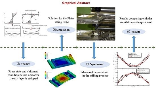
1. Introduction
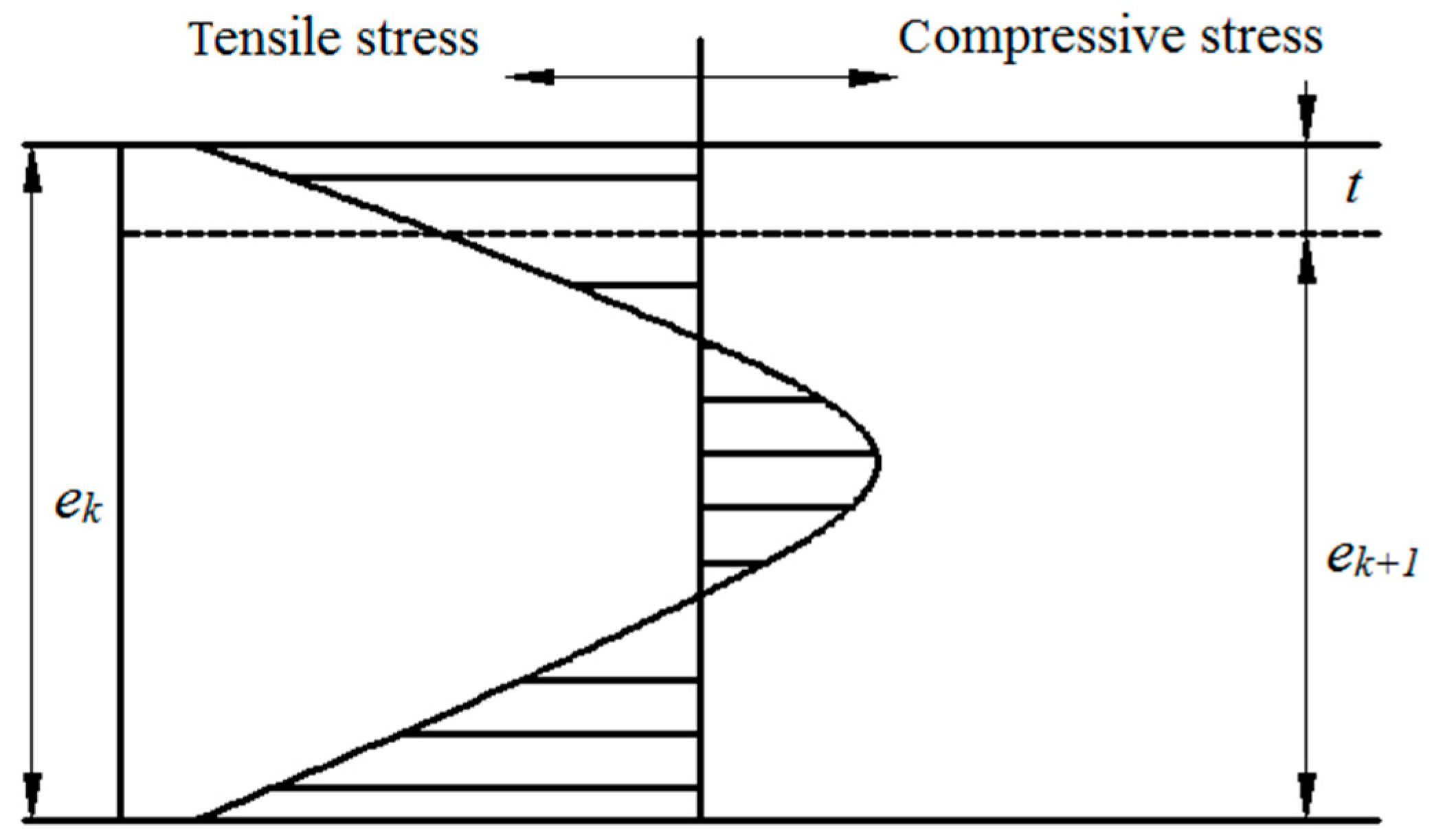
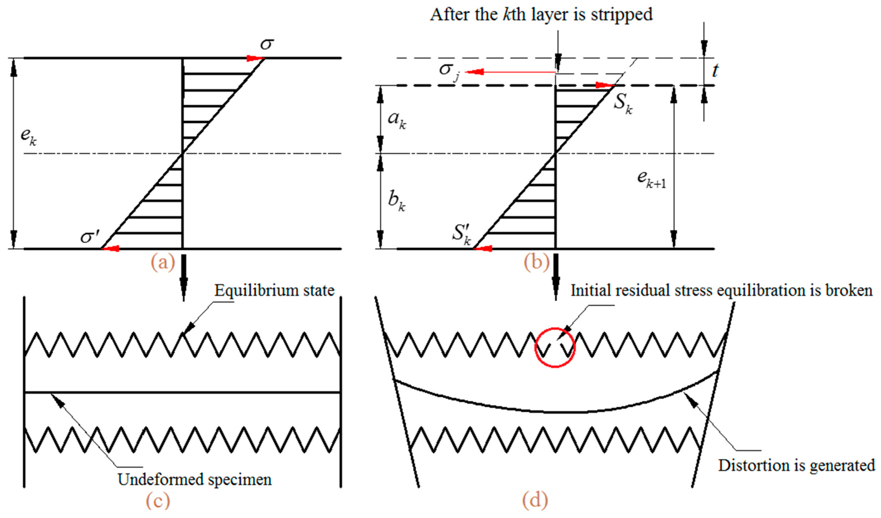
2. Analyses of Deformation Caused by Residual Stress Releasing
3. Analyses of Quasi-Symmetric Processing Technique
4. Solution for the Plates Using FEM
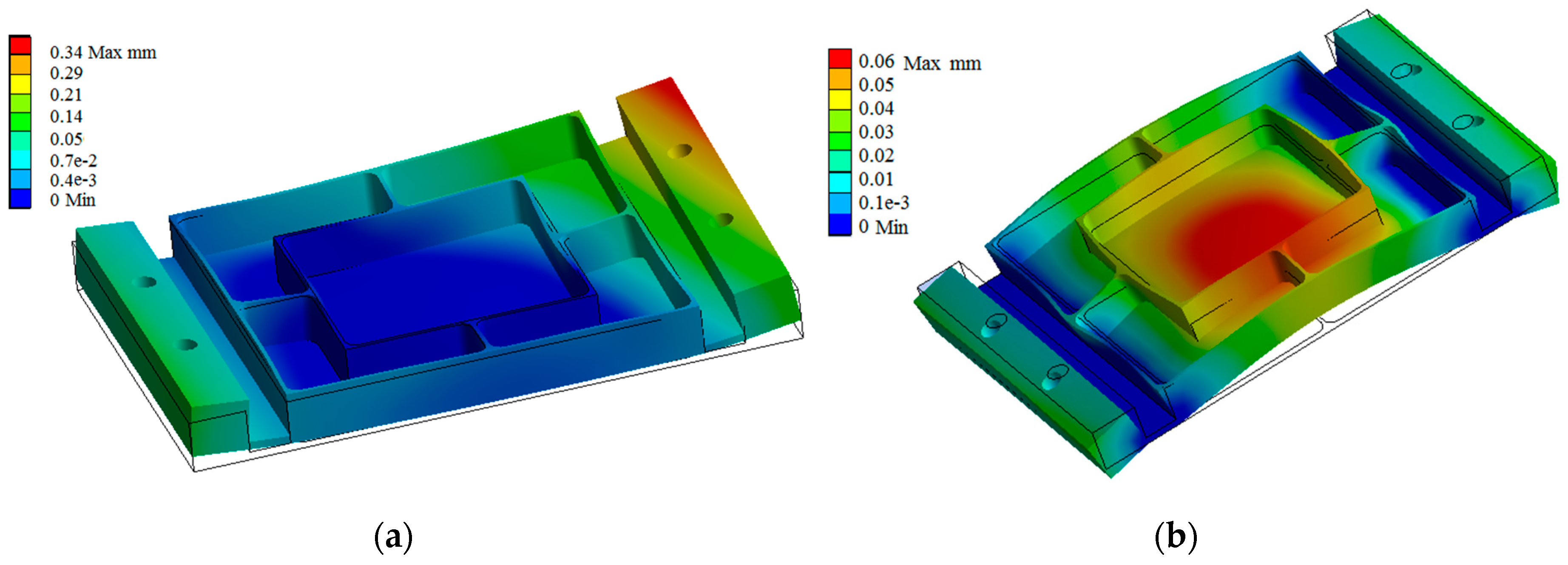
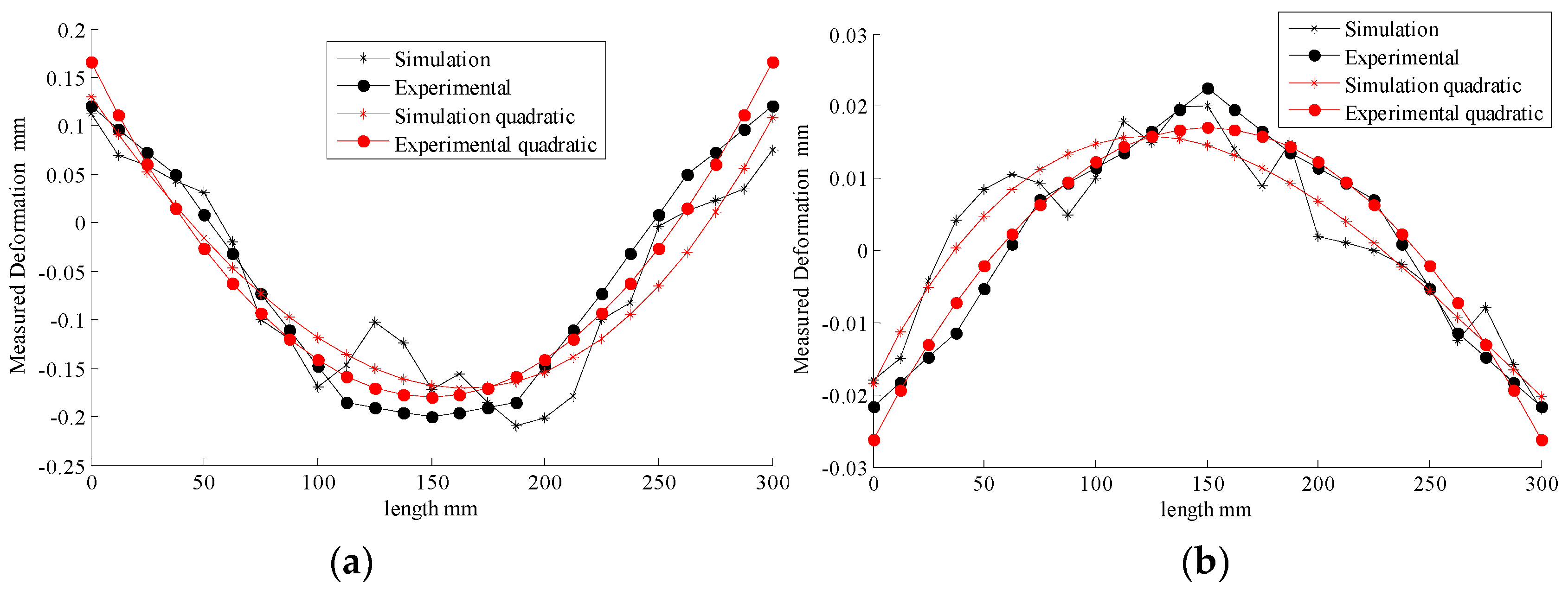
5. Analyses of the Experimental and Simulation Results
- FDM is based on the approximations that facilitate the replacement of differential equations with finite difference equations. As such, the calculation method inevitably displays systematic errors.
- In practice, the boundary conditions are not identical in the simulation and in the experiment. The ideal condition has yet to be determined.
- The residual stress state between simulation and experiment are not consistent. FEM simulating the true condition of residual stress releasing and redistribution, totally, is impossible. Although there are some objective reasons that lead to some certain errors, most of them are within the permitted error range.
6. Conclusions
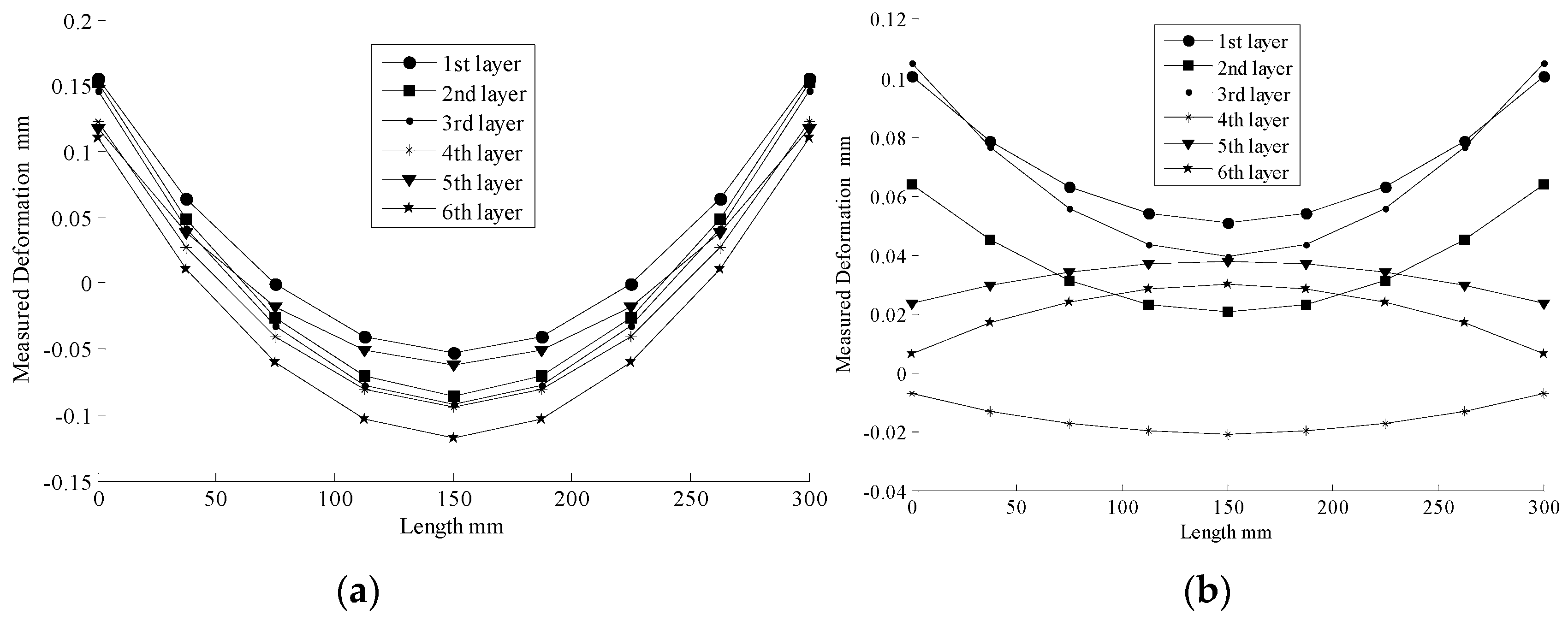
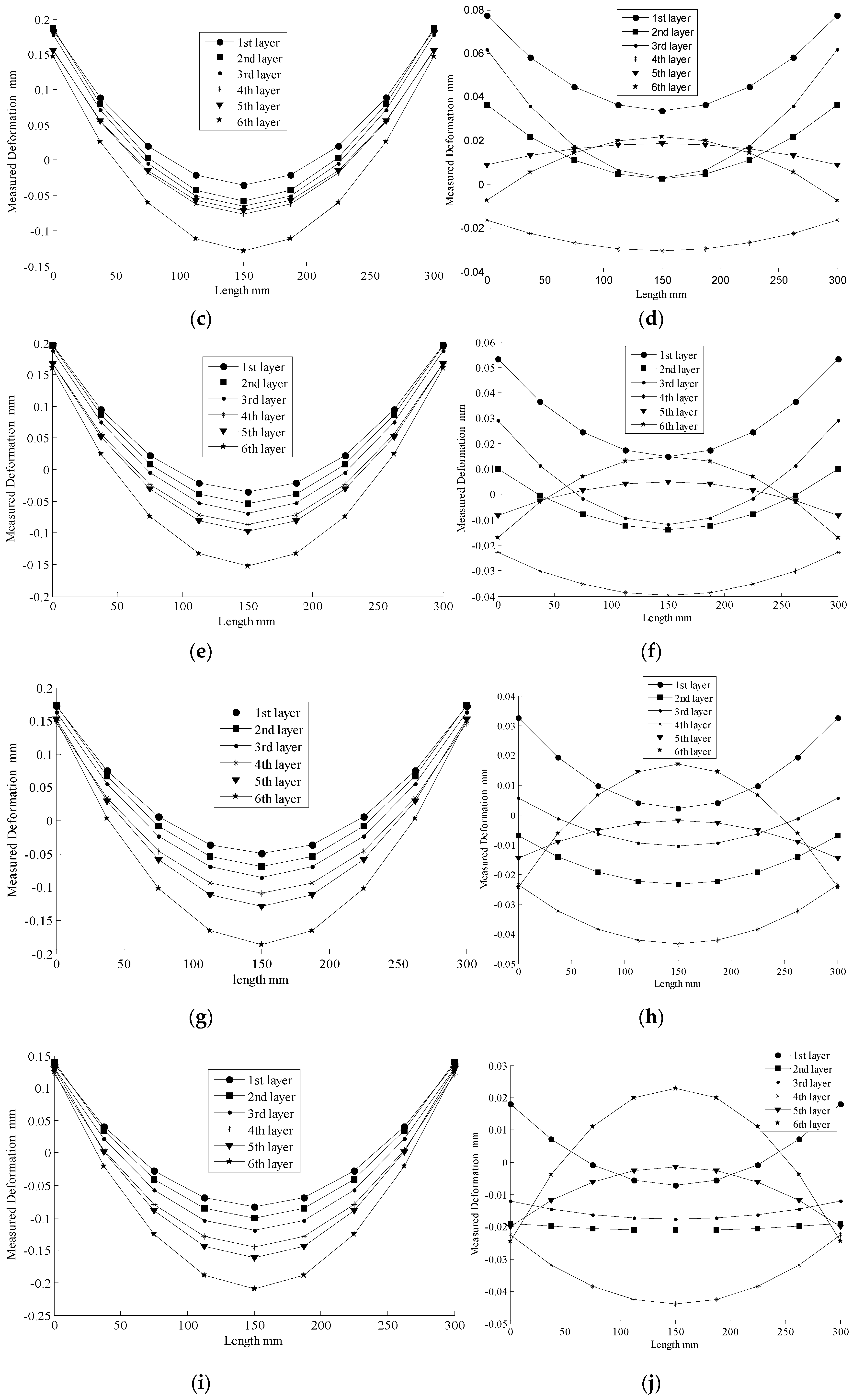
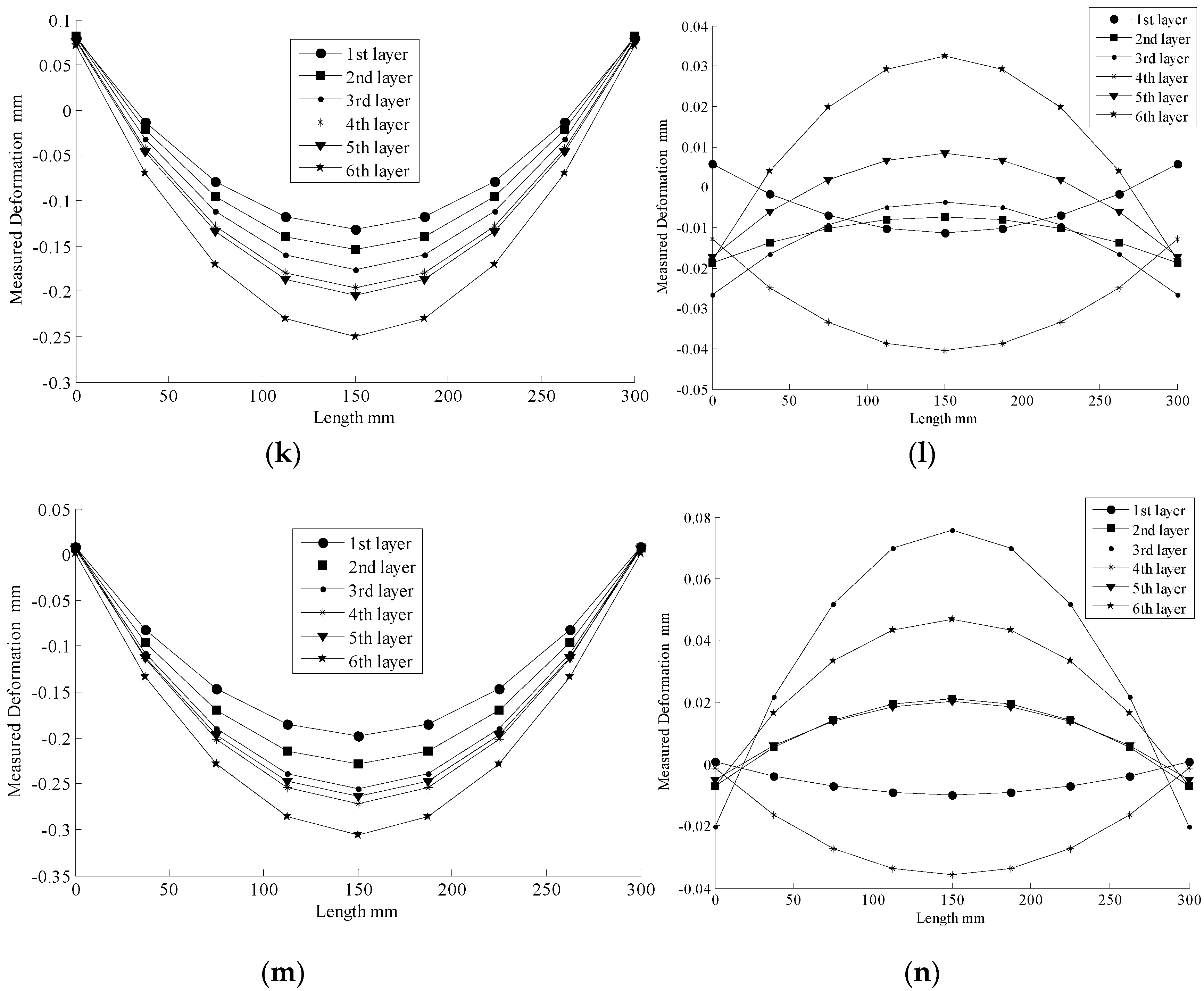
- The maximum deformation value of using a quasi-symmetric machining method is within 20% of that of using a traditional one-side machining method. This result shows the quasi-symmetric machining method is feasible and effective in reducing deformation of monolithic thin-walled components caused by residual stress.
- Errors are low, and most are within 10% for modifying the comparative results of FEM and experimentation. These results confirm that the quasi-symmetric machining method is a reliable and suitable method for releasing deformation.
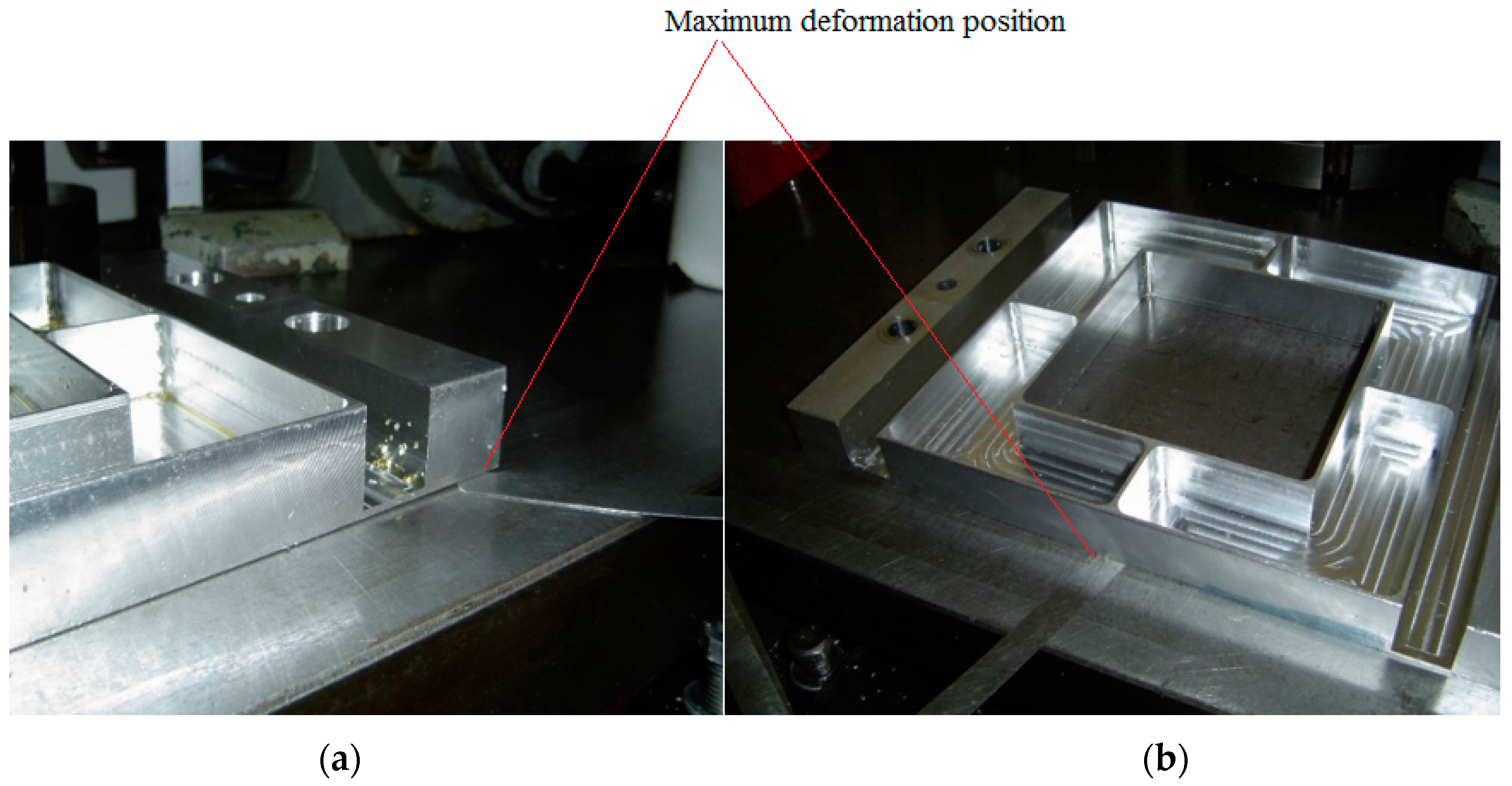
- In the quasi-symmetric machining process, the deformation trend of Specimen 2 is concave downward at both ends, and convex upward at the middle, while the maximum deformation occurs at the middle of the specimen.
Acknowledgments
Author Contributions
Conflicts of Interest
References
- Schubert, E.; Klassen, M.; Zerner, I.; Walz, C.; Sepold, G. Light-weight structures produced by laser beam joining for future applications in automobile and aerospace industry. J. Mater. Process. Technol. 2001, 115, 2–8. [Google Scholar] [CrossRef]
- Mangalgiri, P.D. Composite materials for aerospace applications. Bull. Mater. Sci. 1999, 22, 657–664. [Google Scholar] [CrossRef]
- Dong, H.Y.; Ke, Y.L. Study on machining deformation of aircraft monolithic component by FEM and experiment. Chin. J. Aeronaut. 2006, 19, 247–254. [Google Scholar] [CrossRef]
- Wang, Z.J.; Chen, W.Y.; Zhang, Y.D. Study on the machining distortion of thin-walled part caused by redistribution of residual stress. Chin. J. Aeronaut. 2005, 18, 175–179. [Google Scholar] [CrossRef]
- Herranz, S.; Campa, F.J.; Lacalle, L.N.L.D.; Rivero, A.; Lamikiz, A.; Ukar, E.; Sánchez, J.A.; Bravo, U. The milling of airframe components with low rigidity: A general approach to avoid static and dynamic problems. Proc. Inst. Mech. Eng. B J. Eng. Manuf. 2005, 219, 789–802. [Google Scholar] [CrossRef]
- Bravo, U.; Altuzarra, O.; Lacalle, L.N.L.D.; Sánchez, J.A.; Campa, F.J. Stability limits of milling considering the flexibility of the workpiece and the machine. Int. J. Mach. Tools. Manuf. 2005, 45, 1669–1680. [Google Scholar] [CrossRef]
- Campa, F.J.; Lacalle, L.N.L.D.; Lamikiz, A.; Sánchez, J.A. Selection of cutting conditions for a stable milling of flexible parts with bull-nose end mills. J. Mater. Process. Technol. 2007, 191, 279–282. [Google Scholar] [CrossRef]
- Wang, Z.J.; Chen, W.Y.; Zhang, Y.D.; Chen, Z.T.; Liu, Q. The application of FEM technology on the deformation analysis of the aero thin-walled frame shape workpiece. Key Eng. Mater. 2006, 315, 174–179. [Google Scholar] [CrossRef]
- Jomaa, W.; Songmene, V.; Bocher, P. Surface Finish and Residual Stresses Induced by Orthogonal Dry Machining of AA7075-T651. Materials 2014, 7, 1603–1624. [Google Scholar] [CrossRef]
- Liu, G. Study on deformation of titanium thin-walled part in milling process. J. Mater. Process. Technol. 2009, 209, 2788–2793. [Google Scholar]
- Maurel-Pantel, A.; Fontaine, M.; Thibaud, S.; Gelin, J.C. 3D FEM simulations of shoulder milling operations on a 304L stainless steel. Simul. Model. Pract. Theory 2012, 22, 13–27. [Google Scholar] [CrossRef]
- Eslampanah, A.H.; Aalami-aleagha, M.E.; Feli, S.; Ghaderi, M.R. 3-D numerical evaluation of residual stress and deformation due welding process using simplified heat source models. J. Mech. Sci. Technol. 2015, 29, 341–348. [Google Scholar] [CrossRef]
- Ocana, J.L.; Morales, M.; Molpeceres, C.; Torres, J. Numerical simulation of surface deformation and residual stresses fields in laser shock processing experiments. Appl. Surf. Sci. 2004, 238, 242–248. [Google Scholar] [CrossRef]
- Nouari, M.; Makich, H. On the Physics of Machining Titanium Alloys: Interactions between Cutting Parameters, Microstructure and Tool Wear. Metals 2014, 4, 335–358. [Google Scholar] [CrossRef]
- Denkena, B.; Bickel, W.; Grabowski, R. Modeling and simulation of milling processes including process damping effects. Prod. Eng. 2014, 8, 453–459. [Google Scholar] [CrossRef]
- Abe, T.; Sasahara, H. Residual Stress and Deformation after Finishing of a Shell Structure Fabricated by Direct Metal Lamination using Arc Discharge. Int. J. Automat. Technol. 2012, 6, 611–617. [Google Scholar]
- Wei, Y.; Wang, X.W. Computer simulation and experimental study of machining deflection due to original residual stress of aerospace thin-walled parts. Int. J. Adv. Manuf. Technol. 2007, 33, 260–265. [Google Scholar] [CrossRef]
- Yaghi, A.; Hyde, T.H.; Becker, A.A.; Sun, W.; Williams, J.A. Residual stress simulation in thin and thick-walled stainless steel pipe welds including pipe diameter effects. Int. J. Pres. Vessels Pip. 2006, 83, 864–874. [Google Scholar] [CrossRef]
- Wu, Q.; Li, D.P. Analysis and X-ray measurements of cutting residual stresses in 7075 aluminum alloy in high speed machining. Int. J. Precis. Eng. Manuf. 2014, 15, 1499–1506. [Google Scholar] [CrossRef]
- Husson, R.; Baudouin, C.; Bigot, R.; Sura, E. Consideration of residual stress and geometry during heat treatment to decrease shaft bending. Int. J. Adv. Manuf. Technol. 2014, 72, 1455–1463. [Google Scholar] [CrossRef] [Green Version]
- Huang, X.; Sun, J.; Li, J. Finite element simulation and experimental investigation on the residual stress-related monolithic component deformation. Int. J. Adv. Manuf. Technol. 2014, 77, 1035–1041. [Google Scholar] [CrossRef]
- Li, B.; Jiang, X.; Yang, J.; Liang, S.Y. Effects of depth of cut on the redistribution of residual stress and distortion during the milling of thin-walled part. J. Mater. Process. Technol. 2015, 216, 223–233. [Google Scholar] [CrossRef]
- Muñoz-sánchez, A.; Canteli, J.; Cantero, J.; Miguélez, M. Numerical Analysis of the Tool Wear Effect in the Machining Induced Residual Stresses. Simul. Model. Pract. Theory 2011, 19, 872–886. [Google Scholar] [CrossRef]
- Ballestra, A.; Somà, A.; Pavanello, R. Experimental-Numerical Comparison of the Cantilever MEMS Frequency Shift in presence of a Residual Stress Gradient. Sensors 2008, 8, 767–783. [Google Scholar] [CrossRef]
- Chen, Y.; Tsai, H.; Lu, W.; Chen, L. Effect of Electrical Contact on the Contact Residual Stress of a Microrelay Switch. Sensors 2007, 7, 2997–3011. [Google Scholar] [CrossRef]
- Jiang, X.; Li, B.; Yang, J.; Zuo, X.Y.; Li, K. An approach for analyzing and controlling residual stress generation during high-speed circular milling. Int. J. Adv. Manuf. Technol. 2013, 66, 1439–1448. [Google Scholar] [CrossRef]
- Jiang, X.; Li, B.; Yang, J.; Zuo, X.Y. Effects of tool diameters on the residual stress and distortion induced by milling of thin-walled part. Int. J. Adv. Manuf. Technol. 2013, 68, 175–186. [Google Scholar] [CrossRef]
- Zhang, W.; Lu, J.; Luo, K. Residual Stress Distribution and Microstructure at a Laser Spot of AISI 304 Stainless Steel Subjected to Different Laser Shock Peening Impacts. Metals 2016, 6, 6. [Google Scholar] [CrossRef]
- Mohammadpour, M.; Razfar, M.R.; Saffar, R.J. Numerical investigating the effect of machining parameters on residual stresses in orthogonal cutting. Simul. Model. Pract. Theory 2010, 18, 378–389. [Google Scholar] [CrossRef]
- Toribio, J.; Matos, J.; González, B.; Escuadra, J. Influence of Residual Stress Field on the Fatigue Crack Propagation in Prestressing Steel Wires. Materials 2015, 8, 7589–7597. [Google Scholar] [CrossRef]
- Li, B.Z.; Jiang, X.H.; Jing, H.J.; Zuo, X.Y. High-speed milling characteristics and the residual stresses control methods analysis of thin-walled parts. Adv. Mater. Res. 2011, 223, 456–463. [Google Scholar] [CrossRef]
- Palkowski, H.; Brück, S.; Pirling, T.; Carradò, A. Investigation on the Residual Stress State of Drawn Tubes by Numerical Simulation and Neutron Diffraction Analysis. Materials 2013, 6, 5118–5130. [Google Scholar] [CrossRef]
- Krottenthaler, M.; Schmid, C.; Schaufler, J.; Durst, K.; Göken, M.A. Simple method for residual stress measurements in thin films by means of focused ion beam milling and digital image correlation. Surf. Coat. Technol. 2013, 215, 247–252. [Google Scholar] [CrossRef]
- Hernández, L.; Ponce, L.; Fundora, A.; López, E.; Pérez, E. Nanohardness and Residual Stress in TiN Coatings. Materials 2011, 4, 929–940. [Google Scholar] [CrossRef]
- Rossini, N.S.; Dassisti, M.; Benyounis, K.Y.; Olabi, A.G. Methods of measuring residual stresses in components. Mater. Des. 2011, 35, 572–588. [Google Scholar] [CrossRef] [Green Version]
- Wang, L.; Wang, Y.; Sun, X.G.; He, J.Q.; Pan, Z.Y.; Wang, C.H. Finite element simulation of residual stress of double-ceramic-layer La2Zr2O7/8YSZ thermal barrier coatings using birth and death element technique. Comput. Mater. Sci. 2012, 53, 117–127. [Google Scholar] [CrossRef]
- Chen, J.Q.; Shen, W.L.; Yin, Z.X.; Xiao, S.H. Simulation of Welding Temperature Distribution Based on Element Birth and Death. Hot Work. Technol. 2005, 7, 64–65. [Google Scholar]


| Properties | Young’s Modulus/GPa | Poisson’s Ratio | Density/kg·m3 | Thermal Conductivity/W·m−1·°C−1 | Specific Heat/J·kg−1·°C−1 |
|---|---|---|---|---|---|
| Value | 71 | 0.33 | 2800 | 155 | 960 |
| Milling Cutter Diameter/mm | Rotate Speed of Milling Cutter/r·min−1 | Feeding Speed/mm·m−1 | Axial Feed/mm | Method of Cooling and Lubrication |
|---|---|---|---|---|
| 10 | 3650 | 700 | 0.8 | Oil spray cooling |
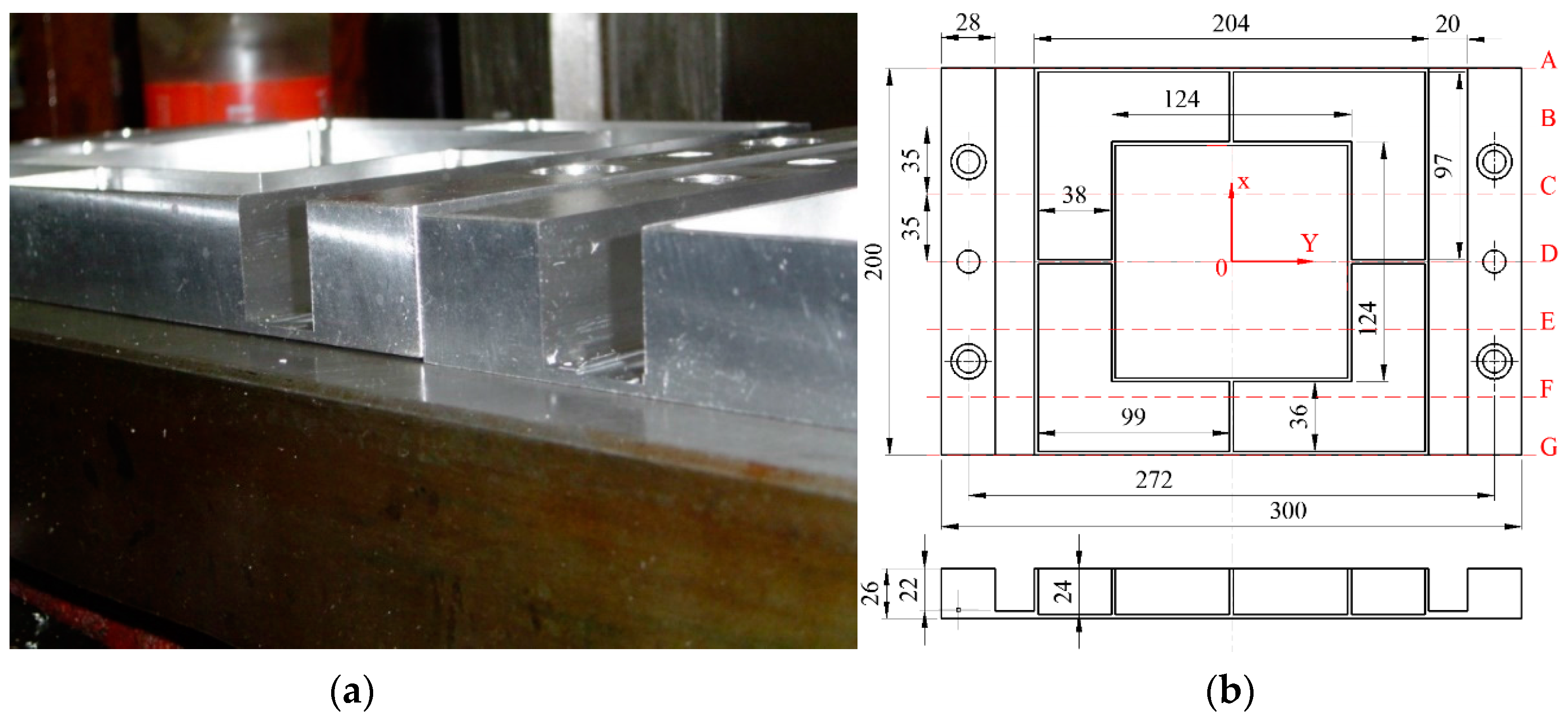
| Cross-Section A/mm | Cross-Section B/mm | Cross-Section C/mm | Cross-Section D/mm | Cross-Section E/mm | Cross-Section F/mm | Cross-Section G/mm | |
|---|---|---|---|---|---|---|---|
| Specimen 1 | 0.2125 | 0.2655 | 0.3060 | 0.3212 | 0.3246 | 0.3232 | 0.3069 |
| Specimen 2 | 0.0201 | 0.0270 | 0.0314 | 0.0451 | 0.0502 | 0.0537 | 0.0589 |
© 2016 by the authors; licensee MDPI, Basel, Switzerland. This article is an open access article distributed under the terms and conditions of the Creative Commons by Attribution (CC-BY) license (http://creativecommons.org/licenses/by/4.0/).
Share and Cite
Wu, Q.; Li, D.-P.; Zhang, Y.-D. Detecting Milling Deformation in 7075 Aluminum Alloy Aeronautical Monolithic Components Using the Quasi-Symmetric Machining Method. Metals 2016, 6, 80. https://doi.org/10.3390/met6040080
Wu Q, Li D-P, Zhang Y-D. Detecting Milling Deformation in 7075 Aluminum Alloy Aeronautical Monolithic Components Using the Quasi-Symmetric Machining Method. Metals. 2016; 6(4):80. https://doi.org/10.3390/met6040080
Chicago/Turabian StyleWu, Qiong, Da-Peng Li, and Yi-Du Zhang. 2016. "Detecting Milling Deformation in 7075 Aluminum Alloy Aeronautical Monolithic Components Using the Quasi-Symmetric Machining Method" Metals 6, no. 4: 80. https://doi.org/10.3390/met6040080