Article

Microstructure and Mechanical Properties of Accumulative Roll-Bonded AA1050A/AA5005 Laminated Metal Composites

Materials Science & Engineering, Institute I, Friedrich-Alexander-Universität Erlangen-Nürnberg (FAU), Martensstr. 5, Erlangen 91058, Germany
*
Author to whom correspondence should be addressed.
Metals 2016, 6(3), 56; https://doi.org/10.3390/met6030056
Submission received: 10 December 2015 / Revised: 23 February 2016 / Accepted: 3 March 2016 / Published: 8 March 2016

Abstract

:
Laminated metal composites (LMCs) with alternating layers of commercial pure aluminum AA1050A and aluminum alloy AA5005 were produced by accumulative roll-bonding (ARB). In order to vary the layer thickness and the number of layer interfaces, different numbers of ARB cycles (4, 8, 10, 12, 14 and 16) were performed. The microstructure and mechanical properties were characterized in detail. Up to 8 ARB cycles, the ultrafine-grained (UFG) microstructure of the layers in the LMC evolves almost equally to those in AA1050A and AA5005 mono-material sheets. However, the grain size in the composites tends to have smaller values. Nevertheless, the local mechanical properties of the individual layers in the LMCs are very similar to those of the mono-material sheets, and the macroscopic static mechanical properties of the LMCs can be calculated as the mean value of the mono-material sheets applying a linear rule of mixture. In contrast, for more than 12 ARB cycles, a homogenous microstructure was obtained where the individual layers within the composite cannot be visually separated any longer; thus, the hardness is at one constant and a high level across the whole sheet thickness. This results also in a significant higher strength in tensile testing. It was revealed that, with decreasing layer thickness, the layer interfaces become more and more dominating.

Graphical Abstract

1. Introduction

Severe plastic deformation (SPD) is a commonly used method of producing ultrafine-grained (UFG) materials. Accumulative roll-bonding (ARB) is one of the most promising SPD methods of producing UFG sheet materials, even when larger material quantities shall be produced. Up to now, a wide range of pure metals and alloys have already been subjected to the ARB process, and especially aluminum alloys are particularly suitable for the ARB process due to its high light-weight potential and good cold roll-bonding capability (see e.g., [1,2,3]). By introducing an UFG microstructure the strength is significantly enhanced compared to the coarse grained counterparts, while the chemical composition and the density of the material are not changed. In this context, it has to be pointed out that either solid solution strengthening or precipitation hardening is the most common hardening mechanisms relevant for aluminum alloys. Additionally, ARB-processing offers the possibility of gaining a significant contribution of Hall-Petch hardening to the strength of the material. In recent years, it has also been shown that the ARB process can be successfully used to produce multi-component materials with tailored properties. Schmidt et al. [4] inserted Al2O3 nanoparticles within the ARB process, leading to an accelerated grain refinement accompanied by a further strengthening. Furthermore, different materials can easily be combined to produce laminated structures, which are denoted as laminated metal composites (LMCs) according to Lesuer et al. [5]. Many studies have been carried out on this area with different materials: Al/Cu [6], Al/Mg [7], Fe/Cu [8], and some others. Due to the excellent results on ARB-processed aluminum mono-material sheets also many Al/Al LMCs have been fabricated (e.g., [9,10]). For many material combinations, the composites produced by ARB are characterized by the combination of the positive aspects of different UFG materials, which are already known for exceptionally mechanical properties such as high strength combined with a satisfying ductility [9,10]. One difficulty of roll-bonding two dissimilar materials is necking and finally rupturing of the harder layer with increasing ARB cycles caused by the difference in plastic flow behavior. Govindaraj et al. [11] found that the onset of these instabilities occurs in the form of a zigzag shear instabilities, resulting in a sinusoidal type of bending of the harder layers and finally thinning if the material exceeds the work hardening point. To suppress this, Göken et al. [12] performed intermediate recrystallization steps after 4 ARB cycles to produce thin layered metal composites of the aluminum alloys AA1050A and AA5005 up to 12 ARB cycles without necking of the harder layer.
In this work, the influence of layer thickness and the number of layer interfaces on the mechanical properties of the LMCs was investigated after different numbers of ARB cycles N (N4, N8, N10, N12, N14 and N16). The aim of this work is to understand in detail how the particular layer interfaces, which can be designed in ARB-processed composited materials, affect the microstructure evolution and the monotonic mechanical properties. In a further study, the fatigue properties of these LMCs were investigated [13].

2. Experimental Section

2.1. The ARB Process

Laminated metal composites consisting of AA1050A (Al 99.5) and AA5005 (AlMg1) were produced by the accumulative roll-bonding process with up to 16 cycles. The chemical composition is listed in Table 1. Sheets of AA1050A and AA5005 were cut to a size of 300 mm × 100 mm × 1 mm and then recrystallized for two hours at 360 °C and cooled in air. Prior to roll-bonding, the surfaces were cleaned by acetone and then wire brushed in order to remove the oxide layer and to ensure a sufficient bonding. Subsequently, the two treated surfaces were stacked on each other and roll-bonded at room temperature using a four high rolling mill (BW 200, Carl Wezel, Mühlacker, Germany) at a nominal thickness reduction of 50% per cycle. The bonded aluminum sheets were air cooled and halved before performing the next cycle. In the first ARB cycle (N1), the AA1050A sheet was roll-bonded with an AA5005 sheet. In the second cycle (N2), the two AA5005 surfaces were roll-bonded to receive a sandwich like structure with the outer layers of AA1050A. Consequently, in the following ARB cycles (N > 3), AA1050A surfaces were always roll-bonded. In order to prevent necking and rupture of the harder AA5005 layer composites with ARB cycles higher than 4 were recrystallized for 10 min at 500 °C and then cooled in air after different ARB cycles (see Table 2). Hence, all final composites exhibit an UFG condition, which is expected to be comparable to an UFG sheet processed by only 4 ARB cycles. The number of layer interfaces and the theoretical material layer thickness of the processed composites are given in Table 2. The calculated layer thickness does not take a potential preferential deformation of the softer AA1050A layer into account. For reference, ARB-sheets with 4, 8 and 12 cycles of AA1050A and AA5005, respectively, were produced applying the same intermediate recrystallization treatments.

2.2. Microstructural Characterization

The LMCs and the mono-material sheets were characterized by scanning electron microscopy (Crossbeam 1540 EsB, Zeiss, Oberkochen, Germany) using secondary electron and backscattered electron contrast techniques, respectively. All sheets were analyzed in side view (rolling direction (RD) × normal direction (ND)). The specimens were mechanically ground down to a grit size of 6 µm and then electropolished (electrolyte A2, Struers, Willich, Germany). The temperature of the electrolyte was between −20 °C and −30 °C using a voltage between 60–80 V for a duration of 10–30 s. The grain size was examined by the line intersection method in RD and ND. However, it was not possible to distinguish between high- and low-angle boundaries for these samples by using the line intersection method. Additionally, to determine the misorientation of the N4 and the N8 composites electron back scattered diffraction (EBSD), measurements were performed using the software HKL Technology CHANNEL5 Flamenco (Oxford Instruments, Abingdon, UK).

2.3. Mechanical Properties

Nanoindentation experiments (Nanoindenter XP, MTS Nano Instruments, Oak Ridge, TN, USA) were performed using a three-sided Berkovich pyramid with the continuous stiffness method (CSM). During CSM mode, a force signal is superimposed by a sinusoidal vibration of 45 Hz, which allows the continuous determination of the contact stiffness. Thus, the hardness and Young’s modulus of the material can be determined as a function of the penetration depth. Tip shape calibration was performed according to the Oliver-Pharr method [14]. In each sample, the hardness profile across the layer interface was measured. In order to increase the spatial resolution, the indentation fields were positioned in an angle of 30° to the rolling direction. The indentation depth was 500 nm for the N4 samples and 250 nm for the N8 and N12 samples, respectively. These values were chosen to minimize the indentation size effect but also to ensure that the deformation around an indentation was mainly in one material. To avoid an influence of the plastic zone around an indent, the distance between the indents was always 20 times the indentation depth [15]. Uniaxial tensile tests were performed on an Instron 4505 universal testing machine (Darmstadt, Germany) at room temperature and a constant engineering strain rate of 10−3 s−1. The tensile specimens were taken in rolling direction and had a gauge section of 10 mm × 4.5 mm × 1 mm in length, width and thickness. For each sheet, 3 tensile tests were conducted.

3. Results and Discussion

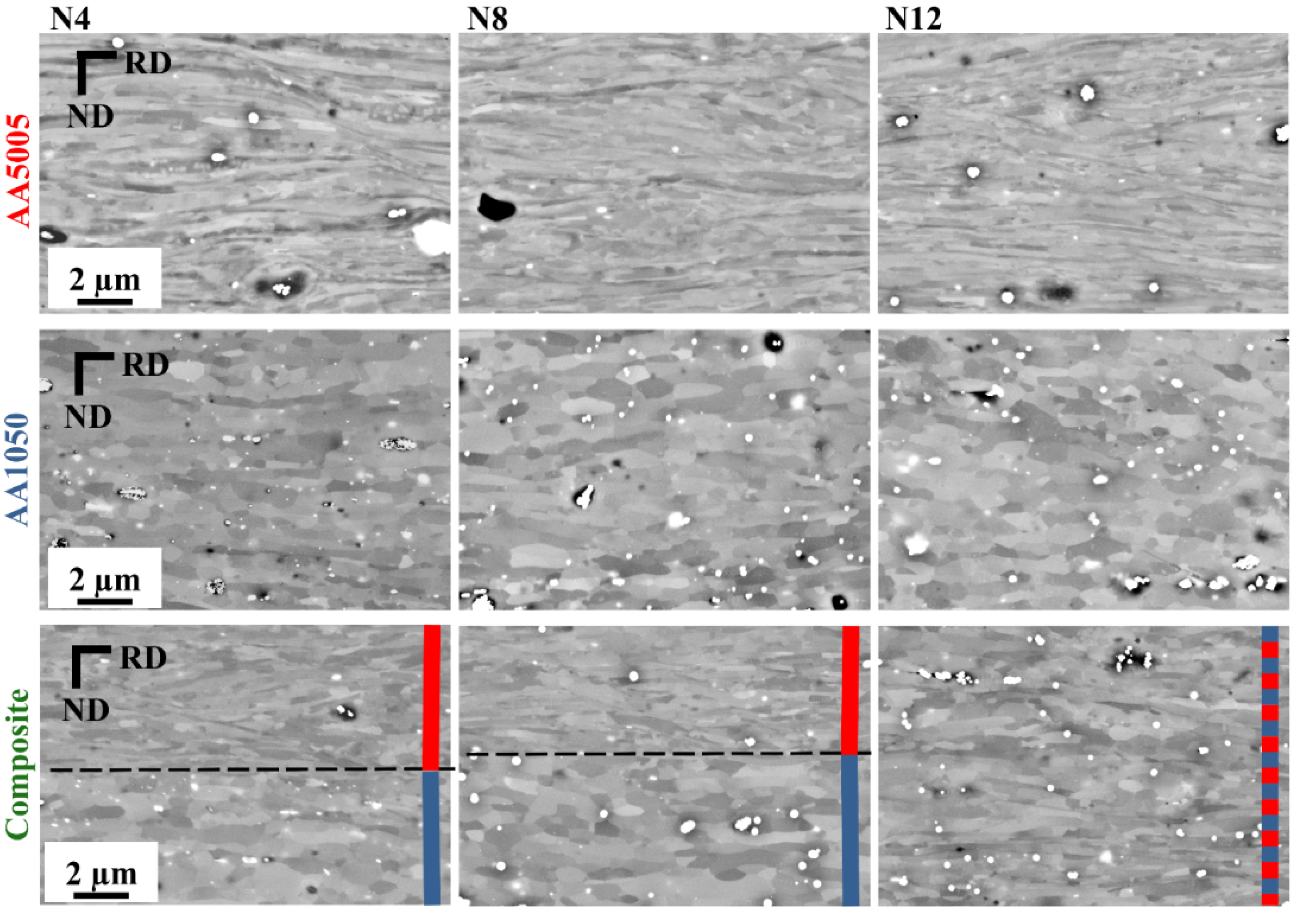
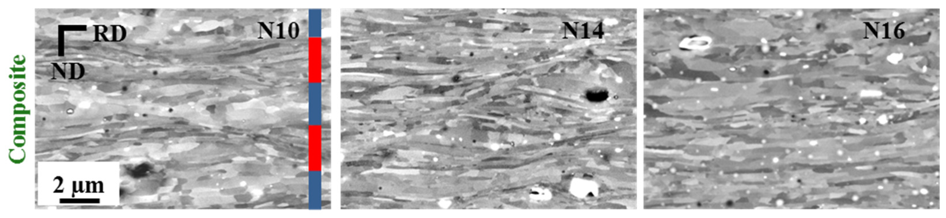
3.1. Microstructural Investigations

The microstructural evolution of the LMCs and mono-material sheets with 4, 8 and 12 ARB cycles are depicted in Figure 1. All ARB-processed samples consist of an ultrafine-grained microstructure with elongated grains along RD. The two material layers can be clearly identified for the N4 and N8 composites. The grain size along ND of AA5005 is much finer than the one of AA1050A, which is likely to be related to the reduced grain boundary mobility in AA5005 [16]. Moreover, some small shear bands can be observed in all AA5005 layers. The amount of solute atoms in AA5005 is higher than in AA1050. Thus, on the one hand, recovery processes of dislocations are hindered, and, on the other hand, the grain boundary mobility is smaller than for AA1050. Both effects contribute to the development of the different grain structures during ARB-processing. After 12 cycles of ARB, the microstructure of the composite is homogenous across the whole sheet thickness, and a clear distinction of the different alloys/layers is no longer possible. Similar microstructures are also present for the N14 and N16 composites, which are depicted in Figure 2. In contrast to the N12, N14 and N16 composites, in the N10 composite the different layers can still be differentiated, Figure 2. Nevertheless, the AA1050A layer is clearly smaller than its theoretical value. This can be explained by mechanical alloying processes due to the strong plastic deformation as well as by diffusion of the solute atoms during the intermediate recrystallization treatments at higher ARB cycles. An evaluation of the diffusion path of solute Mg atoms resulted in a distance of about 10 µm during one recrystallization step. As the layer thickness reaches about 8 µm after 8 ARB cycles, the Mg distribution is supposed to be more or less homogenous and the material contrast diminishes. Thus, the grain refinement during further ARB processing is directly affected. May et al. [16] revealed that a 0.5 percent increase of the Mg content compared to technical pure aluminum already leads to an accelerated grain refinement and a higher dislocation density during ECAP. Furthermore, the high number of layer interfaces and the thin layer thickness directly affects the microstructural evolution of the composites at higher ARB cycles. Due to a difference in the flow properties between the two materials, an additional shear deformation at the layer interfaces occurs during the ARB process, accelerating the grain subdivision and thus leading to finer grains at the layer interfaces (see [10,17]). As the layer thickness in the N12 composite is only twice as large as the grain size in ND, the whole microstructure is influenced by the layer interfaces. Although the individual layers can hardly be separated by a simple SEM-analysis, the term “composite” is used for the N12, N14 and N16 LMCs. Referring to the microstructural and mechanical data of the N12 composite shown below and comparing them to the monolithic counterparts, the term “composite” still appears to be appropriate.
The obtained grain size in ND and RD of the recrystallized samples (N0 and N4r) and after ARB processing (N4–N16) are given in Table 3. The grain size of all intermediate recrystallized samples is very similar to the N4r sample and therefore not given in this table. It must be pointed out that all UFG samples were finally subjected to 4 ARB passes after the last recrystallization step. Hence, the microstructure shall be similar to those directly obtained after 4 ARB cycles. Nevertheless, annihilation processes might be differently effective during the intermediate annealing steps, leading to an increased dislocation density after recrystallization at higher ARB passes. The initial grain size (N0) in the AA1050A layer is clearly coarser than after the intermediate recrystallized step (N4r). For the AA5005 layer very similar grain sizes were measured. Comparing the UFG with the recrystallized samples, the grain size is significantly decreased during the ARB process. The grain size of the AA1050A mono-material sheets slightly rises from 4 to 12 ARB cycles in ND. This increase in ND is associated with an increase in RD, causing a constant aspect ratio of about 2.7, which is related to the equilibrium of dislocation production and recovery [18]. Contrary to that, the grain size of the AA5005 mono-material sheets decreases in ND. In RD, the grain size increases, leading to a rise in the aspect ratio from ARB cycles 4 to 12. For the AA5005 samples, the equilibrium state is not yet reached. In the N4 and N8 composites, the grain size of the AA1050A layer in ND is very similar to the one in the mono-material sheets. This is due to the saturation of the grain size, which already takes place in the AA1050A mono-material sheets after 4 ARB cycles. The additional shear at the interface has therefore an unneglectable influence on the grain size in ND. In contrast to that, the grain size in RD is clearly smaller. The grain size of the AA5005 layer is smaller both in ND and RD. The difference in grain size of both layers compared to the mono-material sheets increases with the number of ARB cycles. This is mainly due to the increasing number of layer interfaces causing additional shear and thus accelerating grain subdivision [17]. As already mentioned for ARB cycles higher than 10, no clear distinction between the two materials can be made and, consequently, only one grain size in each direction was measured (cf. Figure 1 and Figure 2). The grain size gradually decreases with further ARB cycles. The grain size of the N12 and N16 composites approaches the values of the N4 and N8 AA5005 mono-material sheets, respectively. This must be a result of the high number of layer interfaces leading to an enhanced grain refinement in the composites (see Figure 1 and Figure 2.)
The elongated microstructure of the AA1050A layer in the N4 and N8 composite is also clearly visible in the inverse pole figure (IPF) maps measured by EBSD (see Figure 3). The color of each measured point in the EBSD maps indicates the crystallographic direction parallel to the TD of the sheet and corresponds to the direction indicated in the standard stereographic triangle shown in the Figure 3c. The measurement of the orientations reveals that, in ND, the grains are mostly separated by high-angle boundaries (θ > 15°), whereas, in RD, many low-angle boundaries (2° < θ < 15°) are also found, which is typical for cold-rolled or ARB-processed materials (cf. [19]). Comparing the N4 with the N8 composite, the median of misorientation raises from 22.5° to 32.5°. Simultaneously, the fraction of high-angle boundaries increases from 0.62 to 0.79 (see Figure 3c and Table 4). Considering that both composites are processed by 4 ARB cycles after the last recrystallization step, this must be a result of the much smaller microstructure and, probably, of a higher dislocation density after the intermediate recrystallization step at N4 compared to the N0 condition (see Table 3). Furthermore, the increasing number of layer interfaces with rising ARB cycles also leads to a higher amount of shear deformation accelerating the microstructural evolution [10].

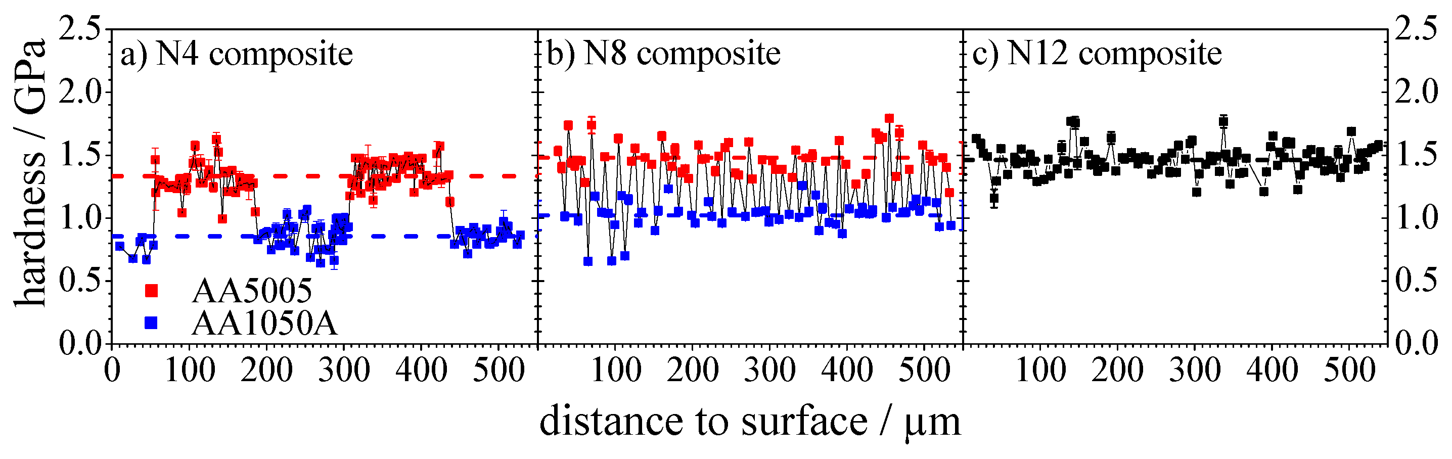
3.2. Nanoindentation Experiments

The mono-material sheets present a very uniform hardness across the sheet thickness. In the AA1050A mono-material sheet the mean hardness rises from 0.8 GPa (N4) to 1.0 GPa (N8 and N12) and saturates at this level, see Table 5. The same trend is found for the AA5005 mono-material sheet but higher hardness values of 1.3 MPa (N4) and 1.6 MPa (N8 and N12) are reached, respectively. In the N4 and N8 composites a clear distinction between the two materials can be made as there is a significant jump in hardness at the layer interface, see Figure 4. The hardness of the AA1050A and AA5005 layers in the N4 and N8 composites are very similar to the ones of the mono-material sheets. The hardness of the N12 composite stays more or less constant across the sheet width and approaches the value of the AA5005 mono-material sheets. This has to be a result of the diffusion during the recrystallization steps accelerating the grain refinement in the AA1050A layer and the high number of layer interfaces causing an additional grain subdivision, see Section 3.1. The increasing hardness from ARB cycle 4 to 8 for the mono-material sheets and the composites cannot be explained by significant changes in the grain size, cf. Table 3. The EBSD measurements of AA1050A layer in the N4 and N8 composites revealed an increase of the misorientation and a higher amount of high-angle boundaries for the N8 composite, see Table 4. Thus, the higher HAGB fraction for the AA1050A N8 mono-material and also for the AA1050A layer in the N8 composite causes the higher hardness, cf. [20,21]. It is assumed that a similar evolution of the misorientation with increasing number of ARB-passes is valid for the AA5005 alloy.

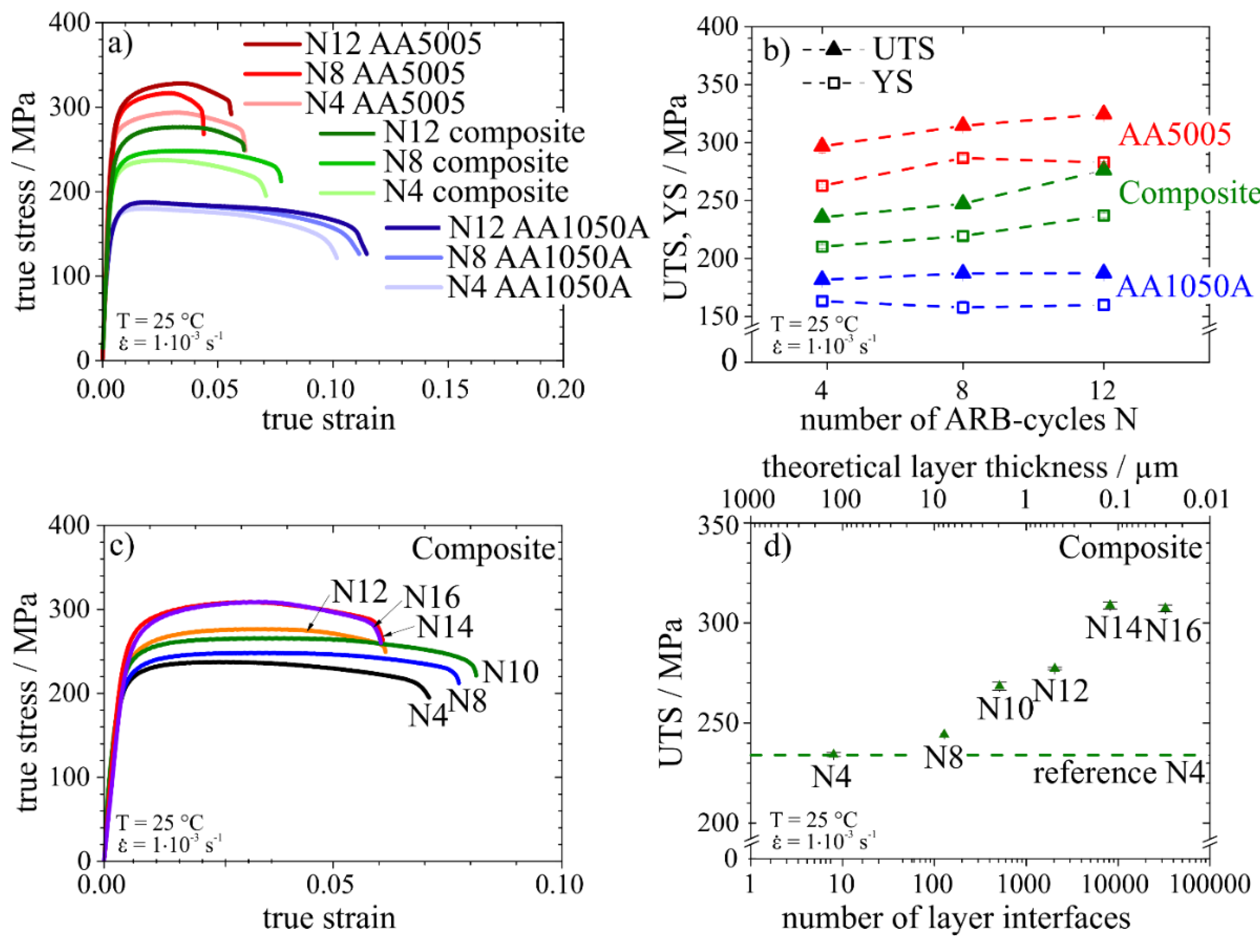
3.3. Mechanical Properties under Monotonic Loads

Representative tensile stress-strain curves of the N4, N8 and N12 samples are depicted in Figure 5a and the evolution of the ultimate tensile strength (UTS) and the yield strength (YS) with respect to the number of ARB cycles in Figure 5b. The AA1050A mono-material sheets exhibit a similar deformation behavior in all three states (N4, N8, N12). All samples start to neck at about 1.8% total elongation. With an increasing number of ARB cycles, the YS remains almost constant, and the UTS increases only slightly between 4 and 8 ARB cycles. This is in good agreement with the nanoindentation experiments revealing only an increase in hardness between ARB cycle 4 and 8. The AA5005 mono-material sheets exhibit a higher amount of hardening compared to AA1050A. Necking starts at about 2.9% total elongation. Both YS and UTS rise with increasing numbers of ARB cycles, though the increase in YS is only small from 8 to 12 ARB cycle. These results also fit the results from the microstructural evolution and nanoindentation experiments, in which the grain size in ND decreases with increasing ARB cycles, leading to an increasing hardness. The stress-strain curves of the composites lie in between the two mono-material sheets. All composites start to neck at about 3.0% total elongation. The strength of the N4 and N8 composites can be calculated as an arithmetic mean of the AA1050A and AA5005 N4 and N8 mono-material sheets, respectively, indicating a linear rule of mixture. This was already observed for many other ARB-processed laminated metal composites (cf. [9,22]). The increase in strength between ARB cycle 4 and 8 is mainly due to the increasing strength of the AA5005 layer. In contrast, the strength of the N12 composite lies clearly above the calculated mean value, indicating that additional effects play an important role. By further increasing the number of ARB cycles to N14 and N16, the strength further increases, Figure 5c,d. However, the strength saturates for the N16 composite. This behavior can be explained, on the one hand, by the further refinement of the grain size comparing to the N12 condition and, on the other hand, by the almost constant, very small grain size for the N14 and N16 conditions. The strong increase in strength between ARB cycle 8 and 14 could be a result of the high number of layer interfaces leading to additional grain subdivision and the accelerated grain refinement. The N16 composite exhibits an identical deformation behavior to the N14 composite, as the layer thickness after 14 ARB cycles is already in the size of the individual grains; hence, every grain is directly affected by a layer interface. Comparing the stress-strain curves of the composites it also turns out that the N14 and N16 composites show a slightly stronger work hardening behavior than the other conditions (see Figure 5c). Regarding the ductility, it becomes evident that, for up to 10 ARB cycles, the elongation to failure of the composites increases up to a total elongation of 8%. This can be attributed to the increasing misorientation in the AA1050A layer (Figure 3). As it was already shown by Höppel et al. [3] for AA1050A, a higher number of ARB passes results in a higher strain rate sensitivity and therefore in an increased elongation to failure of the material. It has been argued [3] that the HAGB fraction primarily governs this behavior. In contrast, for N12, N14 and N16 composites, the elongation to failure becomes smaller, but it still exceeds 5%. This behavior can again be explained by the strain rate sensitivity. As shown in Section 3.1, the two different material layers can be distinguished up to N10. On the one hand, it is assumed that the pronounced strain rate sensitive behavior of the AA1050A material is still maintained. On the other hand, it has to be taken into account that Mg solute atoms in the AA5005 layer diffuse into the AA1050A layer during recrystallization. However, for the N10 composite the diffusion length of the solute Mg atoms during the last recrystallization step is much smaller than the layer thickness. Both aspects are no longer valid if more than 10 cycles are applied. At these numbers of ARB cycles, the composites exhibit a homogenous microstructure across the whole sheet, where it is no longer possible to distinguish between the individual layers. Thus, the ductility decreases and the deformation behavior of the composites become rather similar to the behavior of the less strain rate sensitive AA5005 alloy. Consequently, a remaining persistent AA1050A layer appears to be essential for a satisfying ductility of the composites.

4. Conclusions

In this study, the microstructure and mechanical properties of ARB-processed AA1050A/AA5005 laminated metal composites were investigated. With intermediate recrystallization steps, thin-layered composites were successfully produced up to 16 ARB cycles. It turned out that the number of layer interfaces and the related layer thickness affect the mechanical properties, and strong deviations from the linear rule of mixture are observed. This behavior is attributed to an additional grain refinement caused by the increasing number of layer interfaces. UTS between 235 MPa for the N4 composite and 320 MPa for the N14 and N16 composites were obtained. The best compromise between strength and ductility was provided by the N10 composite, in which a UTS of 270 MPa was achieved by maintaining the ductility of about 8% elongation to failure. This behavior was attributed to the enhanced strain rate sensitivity of the AA1050A layer.
Although the grain size of both materials in the laminate metal composite slightly increases during ARB cycle 4–8, an increase in the mechanical properties measured by nanoindentation and tensile testing was obtained. Similar observations were also made on the ARB-processed AA1050A and AA5005 mono-material sheets. This is mainly a result of the much lower initial grain size after recrystallization and, most likely, of a higher dislocation density for the N8 samples, leading to higher misorientation of the grains. Comparing the N4 and N8 laminate metal composites with ARB-processed AA1050A and AA5005 mono-material sheets, the grain size of both materials is slightly smaller in the composite. At these numbers of ARB cycles, the layer thickness is too high to noticeably influence the mechanical properties globally. Contrary to that, the strength of the N12 composite is clearly higher compared to the mean value calculated from the N12 AA1050A and AA5005 mono-material sheets. Furthermore, the N12 composite exhibits a rather uniform grain structure across the whole sheet thickness and, as a result, a homogeneous hardness distribution which is comparable to the one of the AA5005 mono-material sheets. The hardness of the AA5005 layer stays constant in between ARB cycles 8–12. This indicates that in the N12 composite, where the layer thickness is only twice as large as the grain size in ND, further grain refinement caused by additional shear deformation at the layer interfaces enhances the global strength of the composites. The strength of the N14 and N16 composites is further increased compared to the N12 composite, which can be explained by the increasing number of layer interfaces.

Acknowledgments

The authors gratefully acknowledge the funding of the German Research Council (DFG) which, within the framework of its “Excellence Initiative”, supports the Cluster of Excellence “Engineering of Advanced Materials” at the University of Erlangen-Nürnberg. The authors are also grateful to Jan Philipp Liebig for performing the EBSD measurements.

Author Contributions

Frank Kümmel, Michael Kreuz and Tina Hausöl performed the mechanical characterization and the SEM investigations. Heinz Werner Höppel and Mathias Göken supervised the work and discussed the results with the other authors.

Conflicts of Interest

The authors declare no conflict of interest.

References

  1. Li, L.; Nagai, K.; Yin, F. Progress in cold roll bonding of metals. Sci. Technol. Adv. Mater. 2008. [Google Scholar] [CrossRef]
  2. Saito, Y.; Tsuji, N.; Utsunomiya, H.; Sakai, T.; Hong, R.G. Ultra-fine grained bulk aluminum produced by accumulative roll-bonding (ARB) process. Scr. Mater. 1998, 39, 1221–1227. [Google Scholar] [CrossRef]
  3. Höppel, H.W.; May, J.; Göken, M. Enhanced strength and ductility in ultrafine-grained aluminium produced by accumulative roll bonding. Adv. Eng. Mater. 2004, 6, 781–784. [Google Scholar] [CrossRef]
  4. Schmidt, C.W.; Knieke, C.; Maier, V.; Höppel, H.W.; Peukert, W.; Göken, M. Accelerated grain refinement during accumulative roll bonding by nanoparticle reinforcement. Scr. Mater. 2011, 64, 245–248. [Google Scholar] [CrossRef]
  5. Lesuer, D.R.; Syn, C.K.; Sherby, O.D.; Wadsworth, J.; Lewandowski, J.J.; Hunt, W.H., Jr. Mechanical behaviour of laminated metal composites. Int. Mater. Rev. 1996, 41, 169–197. [Google Scholar] [CrossRef]
  6. Eizadjou, M.; Talachi, A.K.; Manesh, H.D.; Shahabi, H.S.; Janghorban, K. Investigation of structure and mechanical properties of multi-layered Al/Cu composite produced by accumulative roll bonding (ARB) process. Compos. Sci. Technol. 2008, 68, 2003–2009. [Google Scholar] [CrossRef]
  7. Wu, K.; Chang, H.; Maawad, E.; Gan, W.M.; Brokmeier, H.G.; Zheng, M.Y. Microstructure and mechanical properties of the Mg/Al laminated composite fabricated by accumulative roll bonding (ARB). Mater. Sci. Eng. A 2010, 527, 3073–3078. [Google Scholar] [CrossRef]
  8. Kavarana, F.H.; Ravichandran, K.S.; Sahay, S.S. Nanoscale steel-brass multilayer laminates made by cold rolling: Microstructure and tensile properties. Scr. Mater. 2000, 42, 947–954. [Google Scholar] [CrossRef]
  9. Slámová, M.; Sláma, P.; Homola, P.; Uhlíř, J.; Cieslar, M. Multilayer composite Al99.99/AlMg3 sheets prepared by accumulative roll bonding. Int. J. Mater. Res. 2009, 100, 858–862. [Google Scholar] [CrossRef]
  10. Hausöl, T.; Höppel, H.W.; Göken, M. Microstructure and mechanical properties of accumulative roll bonded AA6014/AA5754 aluminium laminates. Mater. Sci. Forum 2011, 667–669, 217–222. [Google Scholar] [CrossRef]
  11. Govindaraj, N.V.; Frydendahl, J.G.; Holmedal, B. Layer continuity in accumulative roll bonding of dissimilar material combinations. Mater. Des. 2013, 52, 905–915. [Google Scholar] [CrossRef]
  12. Göken, M.; Höppel, H.W.; Hausöl, T.; Bach, J.; Maier, V.; Schmidt, C.; Amberger, D. Grain Refinement and Deformation Mechanisms in Heterogeneous Ultrafine-Grained Materials Processed by Accumulative Roll Bonding. In Proceedings of the 33rd Riso International Symposium on Materials Science: Nanometals—Status and Perspective, Roskilde, Denmark, 3–7 September 2012; pp. 31–48.
  13. Kümmel, F.; Hausöl, T.; Höppel, H.W.; Göken, M. Enhanced fatigue life of accumulative roll bonded AA1050A/AA5005 laminated metal composites. Acta Mater submitted for publication. 2016. [Google Scholar]
  14. Oliver, W.C.; Pharr, G.M. An improved technique for determining hardness and elastic modulus using load and displacement sensing indentation experiments. J. Mater. Res. 1992, 7, 1564–1583. [Google Scholar] [CrossRef]
  15. Hay, J.C.; Pharr, G.M. Instrumented Indentation Testing. ASM Handbook Volume 8: Mechanical Testing and Evaluation, 10th Ed. ed; ASM Int: Materials Park, OH, USA, 2000; pp. 232–243. [Google Scholar]
  16. May, J.; Dinkel, M.; Amberger, D.; Höppel, H.W.; Göken, M. Mechanical properties, dislocation density and grain structure of ultrafine-grained aluminum and aluminum-magnesium alloys. Metall. Mater. Trans. Phys. Metall. Mater. Sci. 2007, 38A, 1941–1945. [Google Scholar] [CrossRef]
  17. Quadir, M.Z.; Ferry, M.; Al-Buhamad, O.; Munroe, P.R. Shear banding and recrystallization texture development in a multilayered Al alloy sheet produced by accumulative roll bonding. Acta Mater. 2009, 57, 29–40. [Google Scholar] [CrossRef]
  18. Tsuji, N. Fabrication of Bulk Nanostructured Materials by Accumulative Roll Bonding. In Bulk Nanostructured Materials; Zehetbauer, M.J., Zhu, Y.T., Eds.; Wiley-VCH Verlag GmbH & Co. KGaA: Weinheim, Germany, 2009; pp. 235–253. [Google Scholar]
  19. Huang, X.; Tsuji, N.; Hansen, N.; Minamino, Y. Microstructural evolution during accumulative roll-bonding of commercial purity aluminum. Mater. Sci. Eng. A 2003, 340, 265–271. [Google Scholar] [CrossRef]
  20. Torre, F.D.; Lapovok, R.; Sandlin, J.; Thomson, P.F.; Davies, C.H.J.; Pereloma, E.V. Microstructures and properties of copper processed by equal channel angular extrusion for 1–16 passes. Acta Mater. 2004, 52, 4819–4832. [Google Scholar] [CrossRef]
  21. Kamikawa, N.; Huang, X.; Tsuji, N.; Hansen, N. Strengthening mechanisms in nanostructured high-purity aluminium deformed to high strain and annealed. Acta Mater. 2009, 57, 4198–4208. [Google Scholar] [CrossRef]
  22. Su, L.; Lu, C.; Tieu, A.K.; Deng, G.; Sun, X. Ultrafine grained AA1050/AA6061 composite produced by accumulative roll bonding. Mater. Sci. Eng. A 2013, 559, 345–351. [Google Scholar] [CrossRef]
Figure 1. SEM-micrographs (BSE contrast) of AA5005 and AA1050A mono-material sheets and the AA1050A/AA5005 LMCs after 4, 8 and 12 ARB cycles. The N8 and N12 samples were recrystallized intermediately at N4 or N4 + N8, respectively. The different layers in the composites are indicated by the colored bars at the right and the bonding plane between the different materials by the dashed lines. In the N12 composite no clear distinction of the layers is possible. There, the colored bars represent only the theoretical distribution of the layers.
Metals 06 00056 g001
Figure 2. SEM-micrographs (BSE contrast) of the composites after 10, 14 and 16 ARB cycles. The colored bars indicated for the N10 composite represent only the theoretical distribution of the layers. Due to the small layer size in the N14 and N16 composites, the layer distribution is not indicated.
Metals 06 00056 g002
Figure 3. (a,b) Inverse pole figure (IPF) maps for an AA1050A layer of the N4 and N8 composites, respectively. The low-angle grain boundaries (2° < θ < 15°) are depicted as thin grey lines and high-angle boundaries (θ > 15°) as thick black lines. (c) Cumulative frequency of boundary misorientation angle θ.
Metals 06 00056 g003
Figure 4. Hardness profiles across sheet thickness of the composites after (a) 4, (b) 8 and (c) 12 ARB cycles, respectively. The mean hardness of both phases is indicated by the dashed lines in each graph.
Metals 06 00056 g004
Figure 5. (a) Stress-strain curves and (b) evolution of the YS and UTS of mono-material sheets and composites after different number of ARB cycles. (c) Stress-strain curves of the N4–N16 composites and (d) dependency of the UTS of the composites after different ARB cycles numbers on the number of layer interfaces and the theoretical layer thickness, respectively. All tensile tests were performed at room temperature and at a strain rate of 10−3 s−1.
Metals 06 00056 g005
Table 1. Chemical composition of the aluminum sheets AA1050A and AA5005.
MaterialChemical Composition (wt. %)
SiFeCuMnMgCrZnAlEachTotal
AA1050A<0.25<0.40<0.05<0.05<0.05<0.05<0.07bal.<0.05-
AA5005<0.30<0.70<0.20<0.200.50-1.10<0.10<0.25bal.<0.050.15
Table 2. Intermediate recrystallization steps and the resulting number of layer interfaces and layer thickness of the processes LMCs.
ARB Cycle No.Recrystallized after ARB Cycle No.No. of Layer InterfacesLayer Thickness/µm
NN(2N/2)(1000 × 2/2N)
4-8125.0
841288.0
104 + 65122.0
124 + 820480.5
144 + 8 + 1081920.1
164 + 8 + 1222,7680.03
Table 3. Median grain size and the 95% confidence interval of both materials in the mono-material sheets and in the composites. Please note that no distinction between low- and high-angle grain boundaries is made.
Mono-MaterialAA1050AAA5005
NNDRDaNDRDa
040.54 ± 3.5367.75 ± 8.971.6712.71 ± 1.3416.04 ± 2.181.26
40.324 ± 0.0190.895 ± 0.1022.760.210 ± 0.0100.924 ± 0.1154.41
80.365 ± 0.0220.962 ± 0.1112.630.198 ± 0.0101.057 ± 0.1485.82
120.385 ± 0.0251.048 ± 0.0902.730.190 ± 0.0111.105 ± 0.1505.80
CompositeAA1050AAA5005
NNDRDaNDRDa
4r13.95 ± 1.3118.24 ± 2.361.2015.15 ± 1.3516.47 ± 1.711.18
40.333 ± 0.0260.800 ± 0.0892.400.183 ± 0.0170.733 ± 0.1084.00
80.362 ± 0.0250.876 ± 0.1212.420.178 ± 0.0150.767 ± 0.1174.31
No Distinction of the Two Materials is Possible for ARB Cycles ≥ 10
100.246 ± 0.0281.029 ± 0.1014.19---
120.210 ± 0.0130.962 ± 0.0714.59---
140.198 ± 0.0120.864 ± 0.0744.38---
160.197 ± 0.0080.713 ± 0.0953.39---
Table 4. Mean misorientation and fraction of low-angle boundaries (LAGB) (2° < θ < 15°) and high-angle boundaries (HAGB) (θ > 15°) of the AA1050A layer in the N4 and N8 composite, measured by EBSD.
MaterialMedian of Misorientation/°Fraction of LAGB/%Fraction of HAGB/%
AA1050A N4 Composite22.53862
AA1050A N8 Composite32.52179
Table 5. Mean hardness of both material layers in the composites and the mono-material sheets with increasing numbers of ARB cycles.
No. of ARB Cycles NMono-MaterialComposite
AA1050AAA5005AA1050AA5005
Mean Hardness/GPa
40.83 ± 0.101.30 ± 0.150.85 ± 0.101.33 ± 0.11
81.00 ± 0.071.61 ± 0.081.02 ± 0.121.53 ± 0.13
121.02 ± 0.071.63 ± 0.091.46 ± 0.11 *
* No distinction of the two materials is possible.

