
Modeling of TiAl Alloy Grating by Investment Casting


1
National Key Laboratory of Science and Technology on Precision Heat Processing of Metals, Harbin Institute of Technology, Harbin 150001, China
2
School of Materials Science and Engineering, Harbin Institute of Technology, Harbin 150001, China
3
State Key Laboratory of Advanced Welding and Joining, Harbin Institute of Technology, Harbin 150001, China
*
Author to whom correspondence should be addressed.
Metals 2015, 5(4), 2328-2339; https://doi.org/10.3390/met5042328
Submission received: 19 October 2015
/
Revised: 3 December 2015
/
Accepted: 4 December 2015
/
Published: 9 December 2015
(This article belongs to the Special Issue Intermetallics 2016)
Abstract
:The investment casting of TiAl alloys has become the most promising cost-effective technique for manufacturing TiAl components. This study aimed to investigate a series of problems associated with the investment casting of TiAl alloys. The mold filling and solidification of this casting model were numerically simulated using ProCAST. Shrinkage porosity was quantitatively predicted by a built-in feeding criterion. The results obtained from the numerical simulations were compared with experiments, which were carried out on Vacuum Skull Furnace using an investment block mold. The investment casting of TiAl grating was conducted for verifying the correctness and feasibility of the proposed method. The tensile test results indicated that, at room temperature, the tensile strength and elongation were approximately 675 MPa and 1.7%, respectively. The microstructure and mechanical property of the investment cast TiAl alloy were discussed.
1. Introduction
Energy as well as environmental issues have become the main obstacles for sustaining social and economic development. The substitution of lightweight materials for heavy ones is effective for solving this problem. Aviation and aerospace materials are developed with a predominant focus on the development of lightweight, high-strength materials. TiAl alloys exhibit excellent mechanical, oxidation, and corrosion resistance properties at elevated temperatures (greater than 600 °C), making them a possible replacement for traditional Ni-based superalloy components in the aircraft and automobile industry for increasing the thrust-to-weight ratio and efficiency while decreasing exhaust and noise pollution [1,2,3]. Because of the chemical heterogeneity and physical properties of TiAl alloys, numerous efforts have been focused on the introduction of titanium aluminide into the market, albeit with limited success. A limitation for the “mass market” manufacture of TiAl-based components is that TiAl exhibits very high chemical reactivity, high melting temperature, low ductility, and poor workability. In contrast, casting exhibits a significant advantage for complex-shaped components such as turbine blades, turbocharger rotators and exhaust valves. Because of these issues, investment casting, which can directly produce near-net-shaped components with a good surface finish and low production cost, is a subject of growing interest [4].
Different casting processes are employed for casting TiAl alloys, such as induction-skull melting (ISM), vacuum-arc remelting (VAR), counter-gravity low pressure atmosphere melting (CLIM), plasma-arc melting (PAM), etc. Although most of these processes produce high quality castings, the cost of the products is rather high.
Investment casting exhibits tremendous advantages for the production of quality cast components as it has the key benefits of accuracy, versatility and integrity. As a result, investment casting is one of the most economical methods for producing a wide range of metal castings.
Several efforts have been focused on the thermodynamic stability and mechanism of interaction between refractory materials such as CaO [5,6], Al2O3 [7,8], ZrO2 [9,10] and Y2O3 [11,12] in contact with molten TiAl alloys. Such information is of great interest not only for the purpose of solidification studies but also for the induction melting of TiAl alloys and their investment casting in ceramic molds as well.
The casting process based on experience has the characteristics of high cost and long cycle. In addition, the pouring process is invisible. However, by numerical simulation, cost savings as well as a reduction in production cycles can be achieved. Signification promise and potential have been demonstrated by numerical simulations. This study aims to fabricate a grating with Ti–47Al–2.5V–1Cr (at. %) by investment casting and discusses the relevant microstructure and mechanical properties.
2. Experimental Section
The casting of the TiAl alloy grating was a disk with a diameter of 580 mm, which had a 180 mm hole in the center, and a thickness of 10 mm. Initially, we made a small test disk with a diameter of 400 mm, which had a 120 mm hole in the center, and a thickness of 10 mm. In the following text, we refer to full-size casting as the ultimate goal, and test casting as the minor one. All samples for characterization were cut from the test casting. The full-size casting only employed X-ray non-destructive inspection for the porosity in the casting.
2.1. Numerical Simulation
Experiment processes of TiAl casting were simulated by a finite element method (FEM) software ProCAST package (ESI Group, Paris, France). Table 1 and Table 2 summarize the thermo-physical material properties of the casting and mold, respectively, which were implemented in the preprocessing procedure; the properties of TiAl were given by Sung [13,14], and the properties of ZrO2 were given by ProCAST. The environment temperature in Table 2 was the temperature in the vacuum chamber during melting because it is too difficult to calculate the heat effect of the melting system to the environment. So, we ignored that, and determined it to be room temperature. The filling and solidification behavior was simulated by the calculation procedure. The filling behavior, temperature field and solidification parameters, with respect to the formation of shrinkage porosity, were analyzed during the post-processing procedure. The initial processing parameters used in the simulation were a pouring temperature of 1700 °C, and a filling time of 3 s.

| Temperature/ (°C) | Density/ (kg·m−3) | Specific Heat/ (J·kg−1·K−1) | Thermal Conductivity/ (W·m−1·K−1) | Thermal Diffusion/ (m2·s−1) |
|---|---|---|---|---|
| 25 | 3857 | 598 | 13.2 | - |
| 200 | - | 630 | 16.7 | - |
| 400 | - | 667 | 20.2 | - |
| 600 | - | 703 | 23.1 | - |
| 700 | - | 799 | 25.4 | 8.4 |
| 800 | - | 769.3 | 26.8 | 8.8 |
| 900 | - | 900.1 | 28. | 8.1 |
| 1000 | - | 975.9 | 27.9 | 7.7 |
| 1100 | - | 995.6 | 26.5 | 7.2 |
| 1200 | - | 1140.4 | 27.3 | 6.7 |
| 1600 | 3788 | 786 | 31 | - |
| 1800 | 3612 | 794 | 37 | - |
| Thermophysical Properties | TiAl Alloy | Mold (ZrO2) |
|---|---|---|
| Density/(kg·m−3) | 3788 | 3970 |
| Specific heat/(J·kg−1·K−1) | 598 | 777 |
| Thermal conductivity/(W·m−1·K−1) | 13.2 | 39 |
| Liquidus temperature/(°C) | 1554 | 2323 |
| Solidus temperature/(°C) | 1478 | - |
| Latent heat/(J·kg−1·K−1) | 435 | - |
| Environment temperature/(°C) | 25 | 25 |
2.2. Production of Castings
The alloy used in this study had a nominal composition of Ti–47Al–2.5V–1Cr (at. %, TiAl alloy hereafter). The castings were produced by VAM-150, ZXVAC (Shenyang, China). The charge material was pieces of TiAl alloy ingots produced by vacuum-arc remelting.
In this study, the conventional “lost wax” procedure was employed for fabricating ceramic shell molds. The replicated wax crowns were assembled on the numerically optimized runner and gating system.
The detailed manufacturing processes were described as follows. First, the wax patterns were dipped into the slurry, which was mixed with zirconia sol and ZrO2 powders (diameter < 50 μm), stuccoed by zirconia sand and dried. After the primary coating, wax patterns were coated with a back-up slurry, which comprised alumina and silica sol. Back-up coating process was repeated several times for enhancing the strength of the ceramic molds. Finally, a sealing coat of the back-up slurry was applied. At the end of these processes, the total thickness of the ceramic molds was 7–10 mm. The de-waxing process of the ceramic molds was carried out at about 0.8 MPa and 150 °C in a steam autoclave. After de-waxing, the ceramic molds were sintered at 950 °C for 2 h.
Molds were kept in a refractory-filled can, the vacuum chamber was evacuated and backfilled with argon at a pressure of 8 × 10⁴ Pa and the charge melted. Prior to the pouring process, the ceramic molds were first preheated, and then molten TiAl was poured into the preheated ceramic molds. After removing the ceramic molds, TiAl castings were obtained. There are some negative factors in TiAl casting, such as the static pressure head is low because of low density (3.8 g/cm−3), narrow solidification interval (<80 °C), and bad fluidity. Hence, there is a tendency to employ a pouring temperature as high as possible for improving the quality of the TiAl casting. The machine can melt TiAl at the highest temperature 1700 °C; hence, it is chosen as the pouring temperature.
2.3. Characterization of Microstructure and Mechanical Property
Samples used for characterization were cut from the test casting. All microstructures had been ground and polished electrolytically (Perchloric 6% + Butoxyethanol 34% + Methanol 60%, −30 °C, 35 V, 9 mA). Metallographic specimens were etched by Kroll’s reagent (a mixture of 10 mL HF, 5 mL HNO3 and 85 mL H2O) for observation under an optical microscope. Optical microscopy was performed with an Olympus microscope (Tokyo, Japan). The mechanical property of the castings was characterized by tensile deformation experiments at a constant strain rate (1 × 10⁻⁴ s−1) performed at room temperature. A field emission gun scanning electron microscope (SEM, FEI, QUANTA 200F, Portland, OR, USA) was employed for characterizing the morphologies of the fracture surface.
3. Results and Discussion
3.1. Numerical Simulation for Test Casting
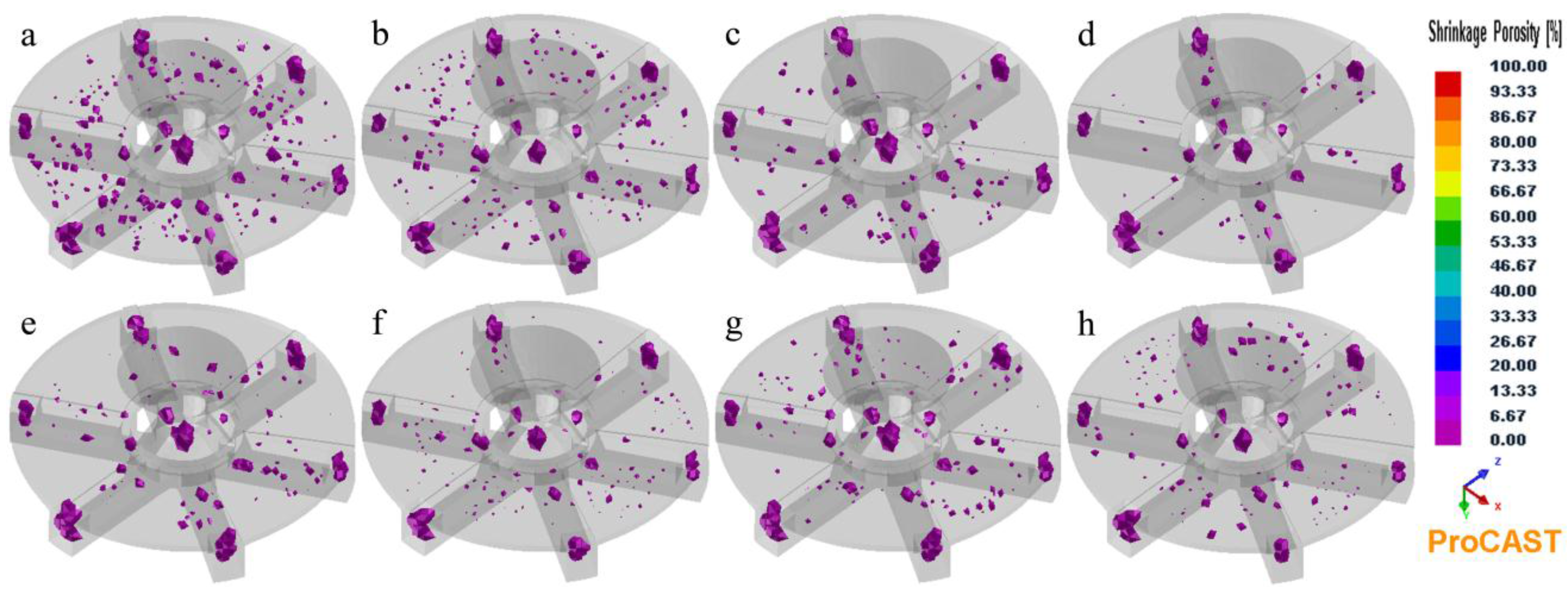
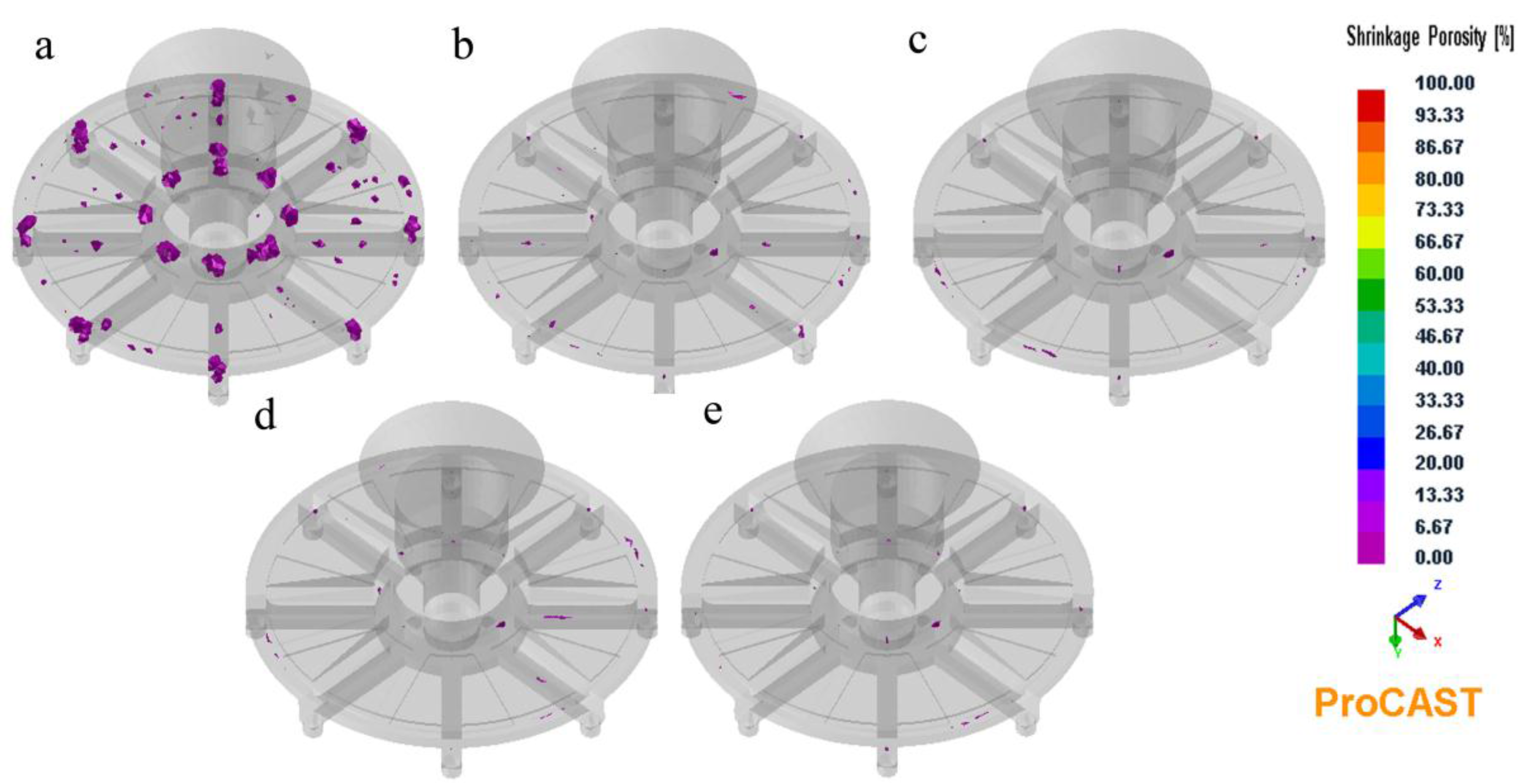
The three-dimensional (3D) model of test casting based on the first design is shown in Figure 1. The mold-filling process and solidification were calculated. All the casting gratings exhibited porosities under different initial conditions, as shown in Figure 2. The results indicated that casting defects are spread throughout the entire cast gratings, and the porosity is considerable. Casting defects are affected by the mold-filling process and the solidification of the cast grating. For a mold temperature of 25 °C and gravity casting, the worst results are obtained from the simulation (Figure 2a), and a large amount of shrinkage pores are spread throughout the entire cast grating. With the increase in the mold temperature to 800 °C, the situation improves slightly (Figure 2b). Moreover, when a centrifugal casting is employed, the situation significantly improves at rotation speeds of 200 rpm and 400 rpm (Figure 2c–f). However, with the increase in the rotation speed to 600 rpm, the amount of shrinkage pores increases (Figure 2g,h).
Figure 1.
Three-dimensional drawing of runner system for test casting.
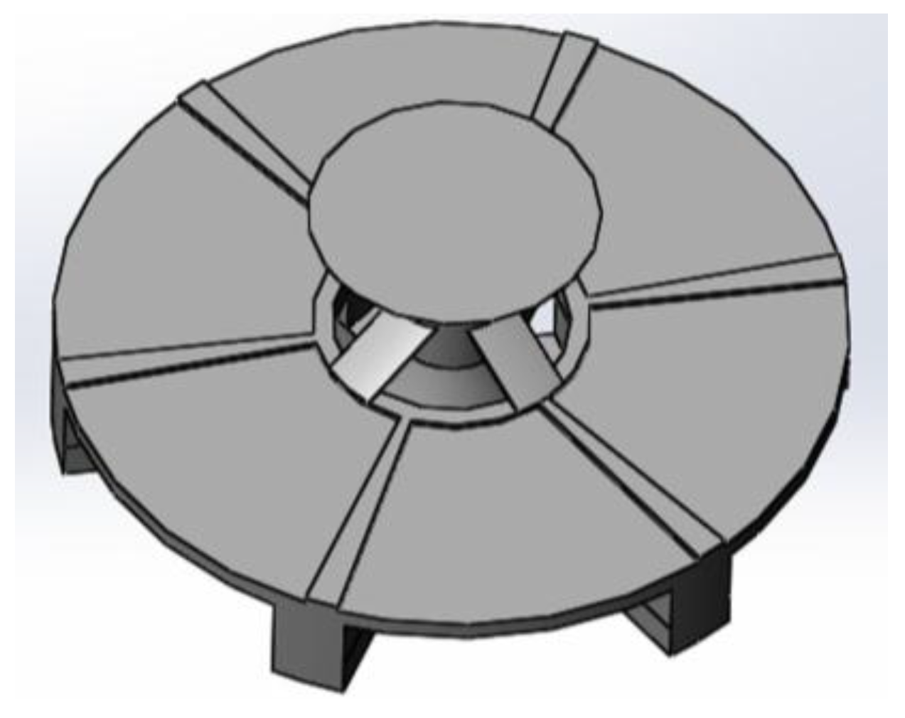
Figure 2.
The predicted shrinkage porosity of test castings: (a) mold temperature of 25 °C and gravity casting (short for 25 °C, 0 rpm); (b) 800 °C, 0 rpm; (c) 25 °C, 200 rpm; (d) 800 °C, 200 rpm; (e) 25 °C, 400 rpm; (f) 800 °C, 400 rpm; (g) 25 °C, 600 rpm; (h) 800 °C, 600 rpm.
Figure 2.
The predicted shrinkage porosity of test castings: (a) mold temperature of 25 °C and gravity casting (short for 25 °C, 0 rpm); (b) 800 °C, 0 rpm; (c) 25 °C, 200 rpm; (d) 800 °C, 200 rpm; (e) 25 °C, 400 rpm; (f) 800 °C, 400 rpm; (g) 25 °C, 600 rpm; (h) 800 °C, 600 rpm.

Because of the contact with the mold, the front-flowing molten metal loses a large amount of heat, which causes a sudden decrease in temperature, and the molten metal may no longer flow to the cold end of the mold. The possibility of shrinkage porosity slightly decreased with a high mold temperature. For a given pouring temperature and mold temperature, the molten TiAl alloy fills the mold at a rapid rate, it gets a long time to feed, and decreases the possible formation of cast defects. In the case when the pouring rate is limited by the casting equipment, the action of the centrifugal force results in the spreading of the molten metal. With this runner design, the liquid flow would break under excessive centrifugal force; hence, a high rotation speed causes deterioration instead (Figure 2g,h). When the temperature of the frontier molten metal rapidly decreases, a large number of dendrites would mix in with the molten alloy, which would increase the viscosity of the molten alloy and flow resistance, slowing down of the flow rate of the molten alloy. While centrifugal force stirs the molten alloy, dendrites mixed with the latter molten alloy with higher temperature for remelting. By comparing the two cases, a mold temperature of 25 °C and gravity casting and a mold temperature of 800 °C, 400 rpm, when the mold is completely filled, the solid fractions obtained are 11.3% and 0.2%, respectively.
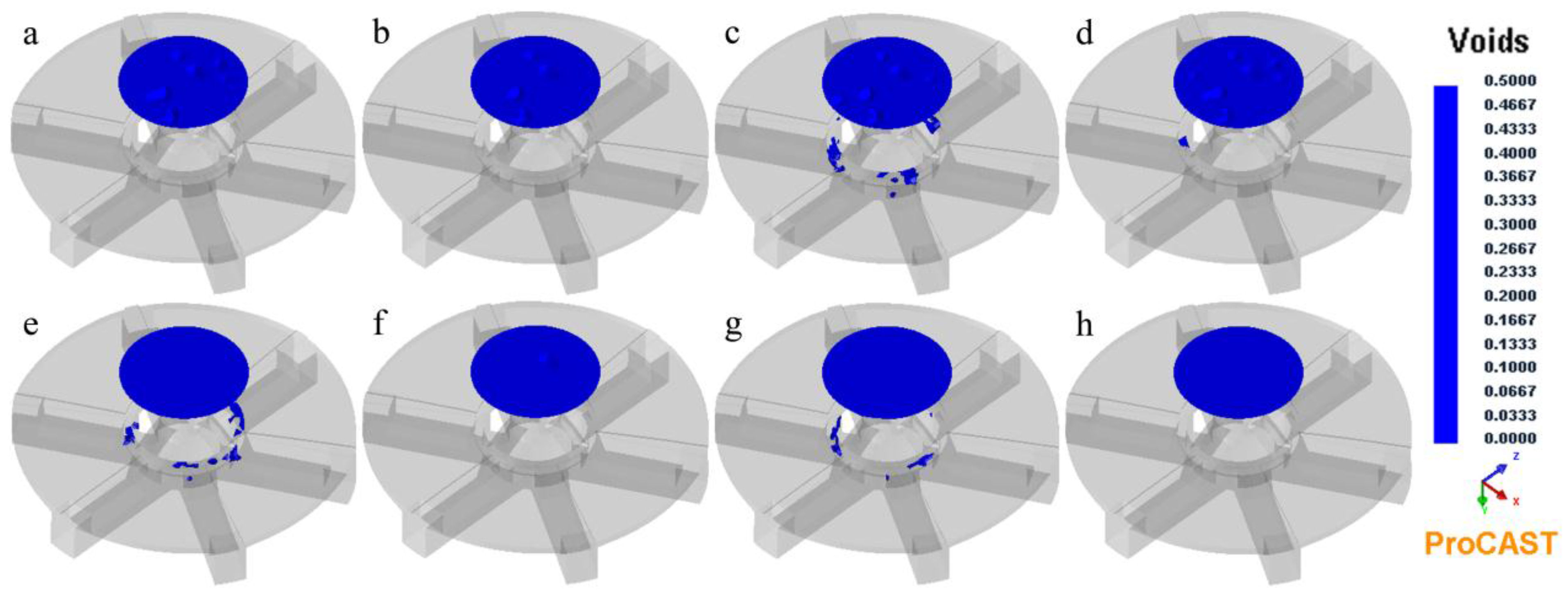
For shrinkage porosity, Figure 2d showed best situation, Figure 2f was the second and Figure 2e was the third. However, Figure 3d,e exhibited voids, and Figure 3f was free of voids. In ProCAST, the voids predicted represent not only air bubbles but also oxide layers trapped in areas where fluid flow is restricted. Hot Isostatic Pressing (HIP), which is a necessary step in the foundry industry, can eliminate voids but does not remove micro-porosity, which means that voids are more serious than porosity. Hence, a mold temperature of 800 °C and a rotation speed of 400 rpm are probably good choices for the test casting, which exhibited porosity slightly more than that observed at a mold temperature of 800 °C and a rotation speed of 200 rpm, albeit free of voids.
Figure 3.
Predicted voids of test castings, (a–h), the same as the Figure 2.
Figure 3.
Predicted voids of test castings, (a–h), the same as the Figure 2.

3.2. The Quality of Test Casting
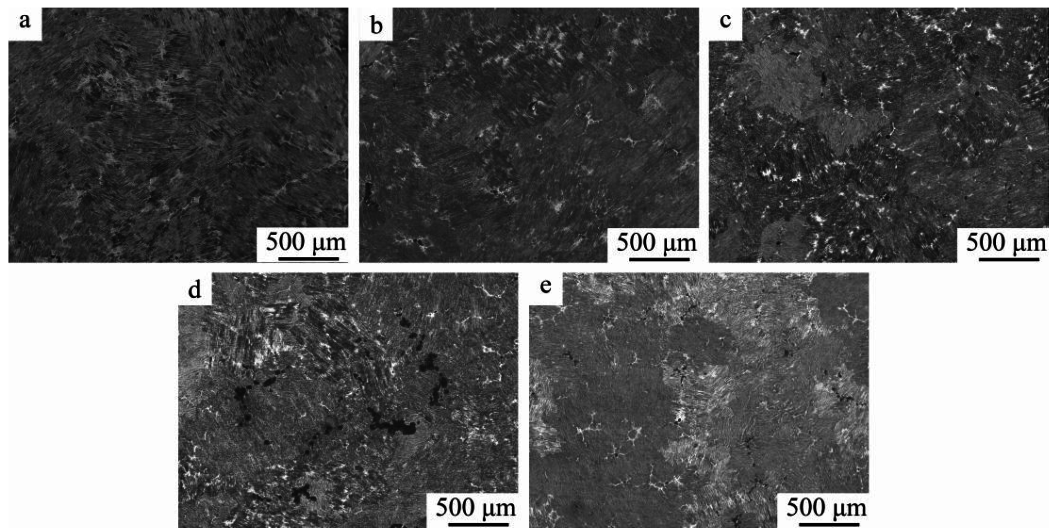
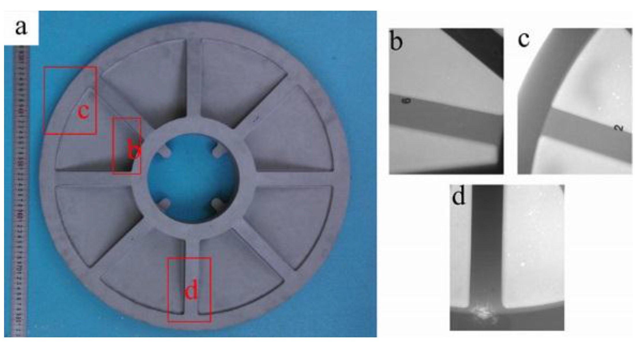
Figure 4a shows TiAl alloy test castings, which show visible pores on the surface. Figure 4b shows the location of the samples for metallographic observation and tensile test. As shown in Figure 5 and Figure 6c,d, the orientation of the metallographic section is tangential, and Figure 6a shows the contact surface between the disk and runner.
Figure 4.
Test casting (a,b) showed the specimen locations: I, II, III, IV, and V, for Figure 5a–e, respectively; VI for Figure 6a; Tensile for the tensile test.
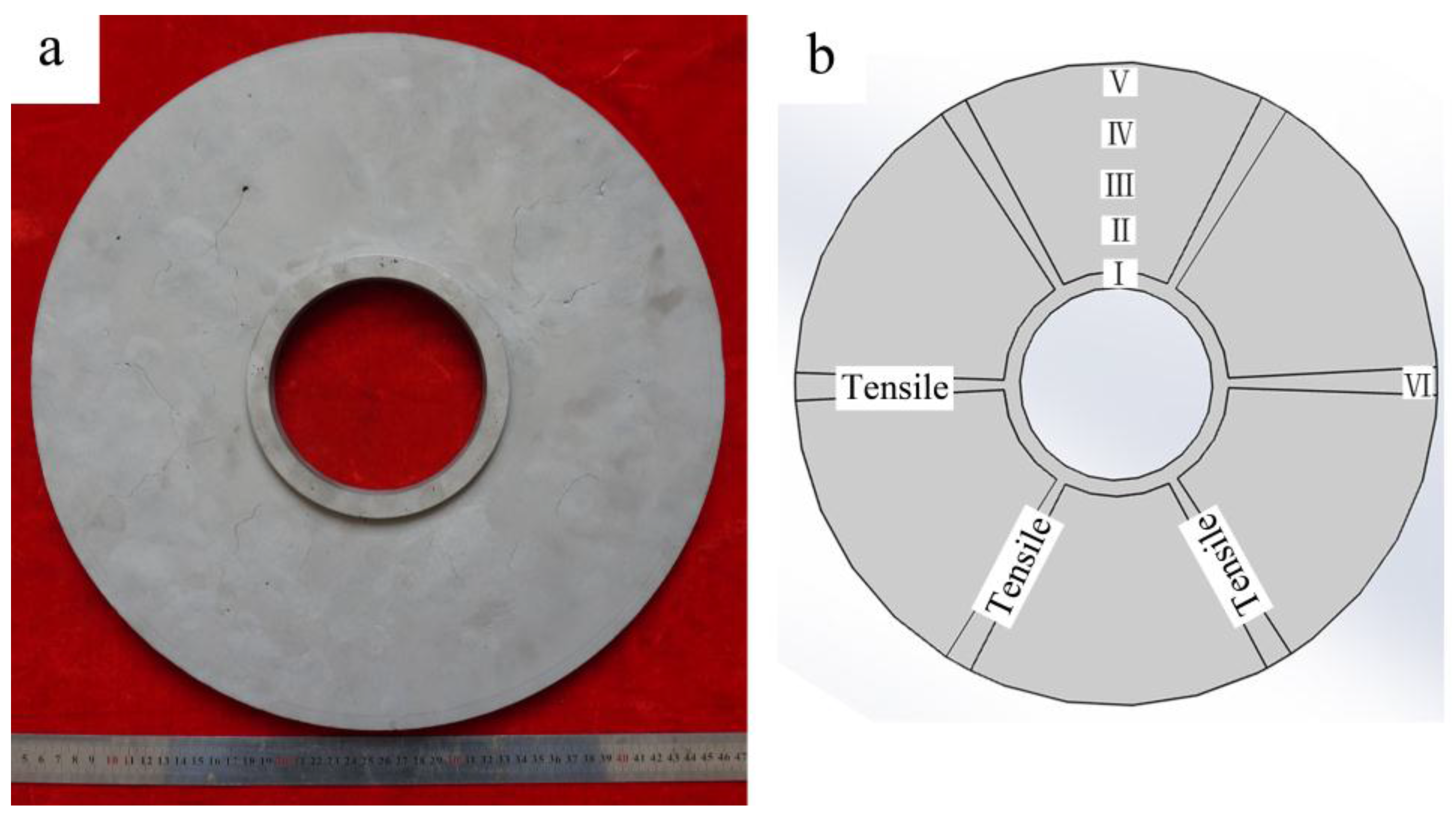
Figure 5.
Optical microstructure of test casting (a–e) were from the center hole to the outer edge, and the interval between the two samples measured 20 mm.
Figure 5.
Optical microstructure of test casting (a–e) were from the center hole to the outer edge, and the interval between the two samples measured 20 mm.

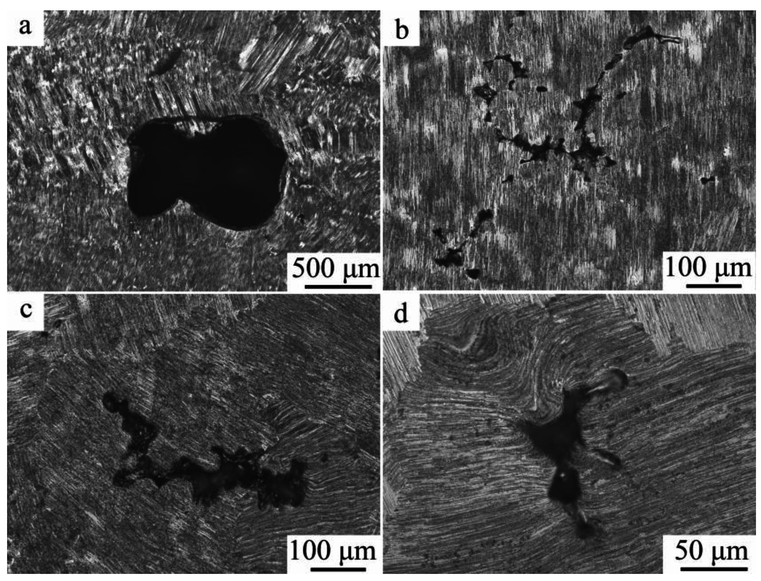
Figure 6.
Micro-defects of test casting, (a) pore and (b–d) shrinkage.

Figure 5 shows a typical fully lamellar microstructure of as-cast TiAl, which contains a small amount of finely segregated γ-grains which are mainly located at the lamellar grain boundaries or in the interdendritic region as a result of the occurrence of double peritectic reactions during solidification. The microstructure does not significantly differ from the center hole to the outer edge; however, the casting defects are not the same everywhere. Figure 5a,b,e show micropores, and Figure 5c,d show extensive micro-porosity. Compared with the simulation data as shown in Figure 2d, the predicted shrinkage porosity of casting is in agreement with the experimental data, which show that the shrinkage porosity of casting enriches in the center of the casting and is absent near the center hole and outer edge. Figure 6a shows that a big hole appeared in runner, which is proved by Figure 7b. Figure 6a,b show that there is no effect of shrinkage on the fully lamellar microstructure; however, Figure 6c,d, show bending lamellar microstructure near the shrinkage. Figure 7a shows the slice view of the disk, and Figure 7b shows the slice view of the rib. As shown in Figure 7a, marginal shrinkage porosity is observed, and the amount of shrinkage porosity is significantly less than that in Figure 7b. The predicted shrinkage porosity by ProCAST is the probability, and Figure 5 meets the left half of Figure 7a—Figure 5a,b,e is almost porosity free, Figure 5c shows a few pores, and Figure 5d shows enrichment of shrinkage porosity.
Figure 7.
Slice view at a mold temperature of 800 °C and rotation speed of 400 rpm, (a) disk and (b) rib.
Figure 7.
Slice view at a mold temperature of 800 °C and rotation speed of 400 rpm, (a) disk and (b) rib.

3.3. Mechanical Property for Test Casting
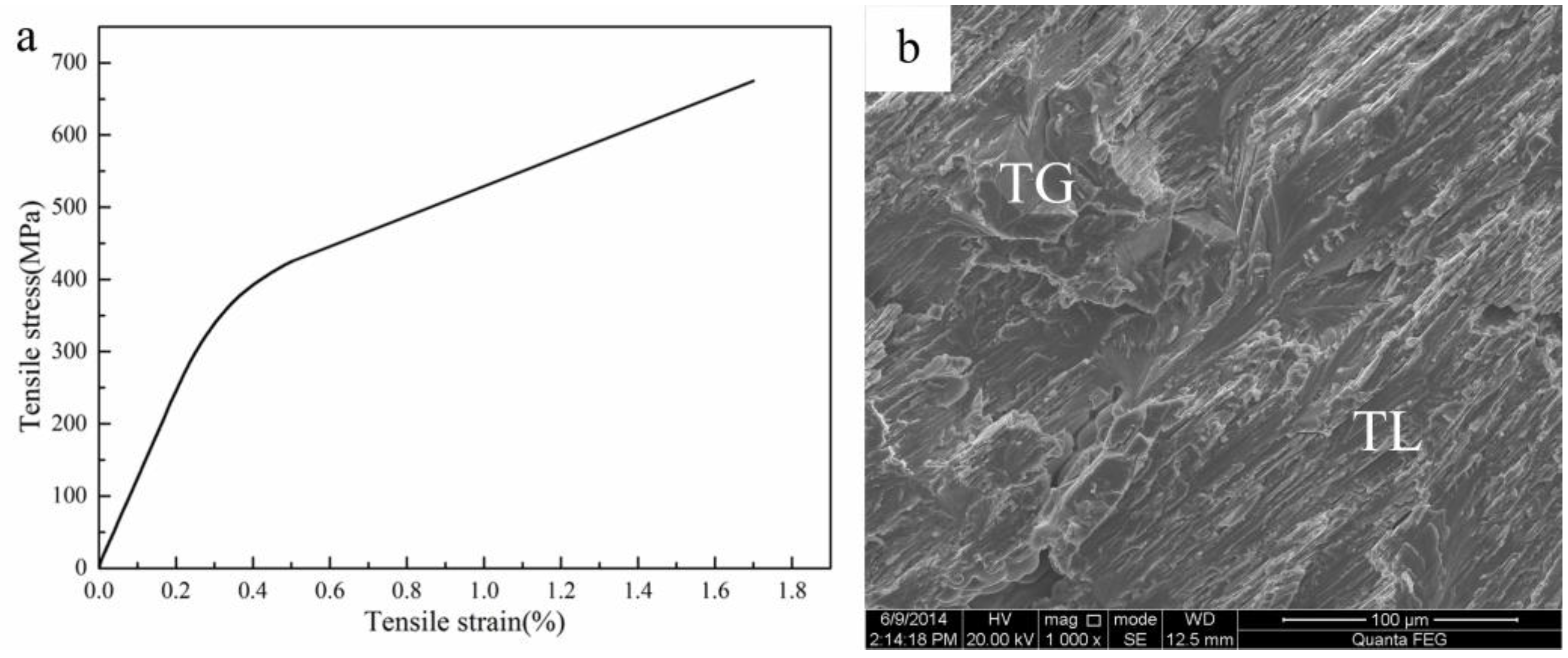
Figure 8a shows the mechanical property of the investment cast TiAl alloy at room temperature. The tensile strength and elongation at room temperature are about 675 MPa and 1.7%, respectively. The results obtained from this study are in good agreement with the data reported previously [4,15]. The mechanical property of a casting not only depends on its microstructure but also on the alloy composition, casting conditions and heat treatment. Figure 8b shows the fracture surface of an investment cast TiAl specimen at room temperature that presents an irregular and tortuous surface. It can be concluded that the main failure modes are inter-granular fracture in equiaxed γ-grains and trans-lamellar cracking in lamellar grains. The minor failure modes are trans-granular cracking in equiaxed γ-grains and local ductile failure in lamellar grains. It is suggested that the retained as-cast lamellar structure has a detrimental effect on tensile property, especially elongation. This is mainly related to the strong anisotropic flow stress behavior of the α2/γ lamellar [2].
Figure 8.
Tensile test stress-strain curve obtained at room temperature (a) and fracture surface (b) of as-cast TiAl specimen, transgranular (TG) and translamellar (TL).
Figure 8.
Tensile test stress-strain curve obtained at room temperature (a) and fracture surface (b) of as-cast TiAl specimen, transgranular (TG) and translamellar (TL).

3.4. Numerical Simulation for Full-Size Casting
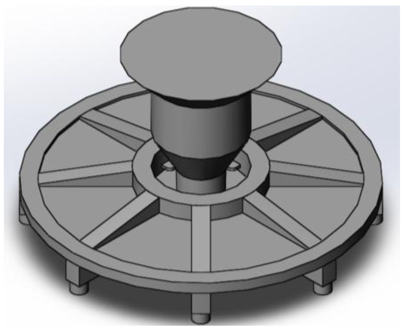
From simulation results and the microstructure of the test casting, the thickness of the disk is too small to be compared with its diameter. Hence, the mold is hardly full with molten alloy in a gravity cast. However, when a centrifugal force is employed, the molten alloy can be easily torn in the flat disk. In this case, the advantage of centrifugal force is weakened. Hence, the main ideas of improvement with respect to the runner system are to provide a sufficient molten alloy to fill the mold and keep the fluid stable. Therefore, it is decided to moderately increase the gate size, as shown in Figure 9.
Figure 9.
Three-dimensional drawing of runner system for full-size casting.

The simulation results obtained for the test casting show that mold temperature is not a factor that decides the quality of casting below 800 °C. On the other hand, high mold temperature causes a heavy interfacial reaction [13], hence the preheat temperature of the mold for the full-size casting decreases.
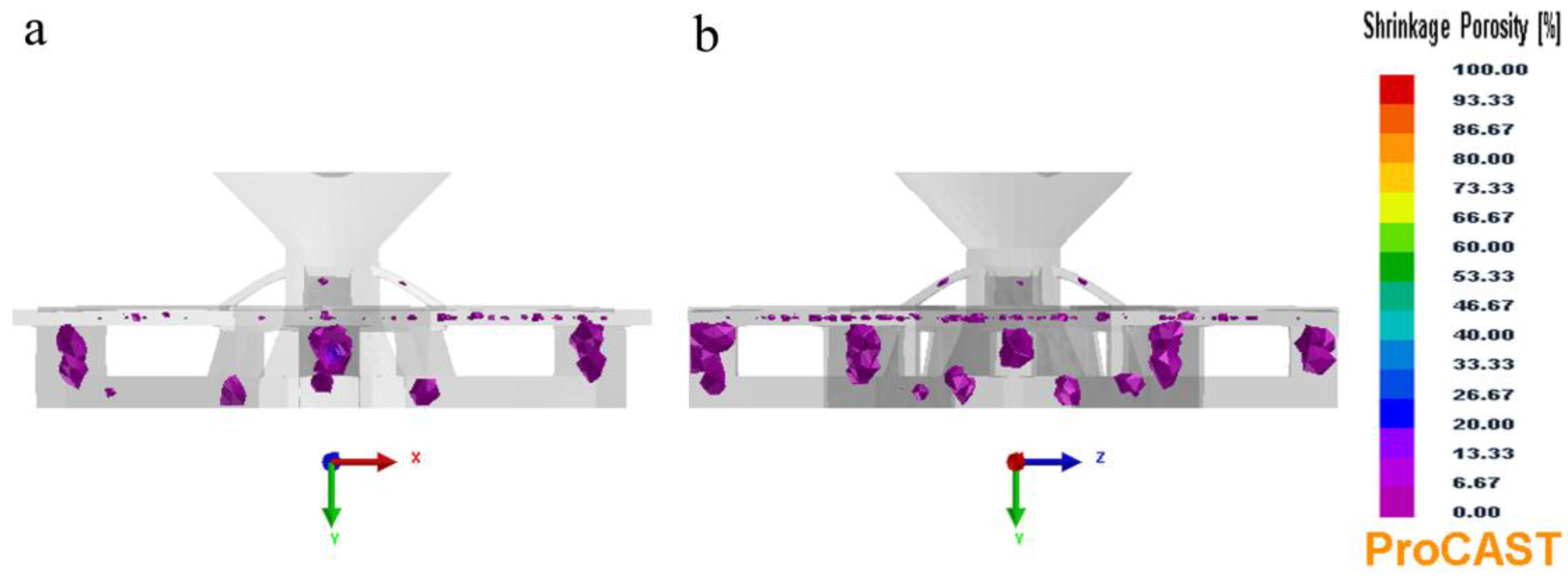
Figure 10 shows the shrinkage porosity in the full-size castings: casting defects in the optimized design significantly decrease more when compared to those in the test casting. Because of the enlarged filling gate, the centrifugal effects exhibit dramatic improvement of the mold filling (Figure 10b–e).
Figure 10.
The predicted shrinkage porosity of full-size castings, (a) mold temperature of 600 °C and gravity casting (short for 600 °C, 0 rpm); (b) 200 °C, 200 rpm; (c) 400 °C, 200 rpm; (d) 600 °C, 200 rpm; (e) 600 °C, 400 rpm.
Figure 10.
The predicted shrinkage porosity of full-size castings, (a) mold temperature of 600 °C and gravity casting (short for 600 °C, 0 rpm); (b) 200 °C, 200 rpm; (c) 400 °C, 200 rpm; (d) 600 °C, 200 rpm; (e) 600 °C, 400 rpm.
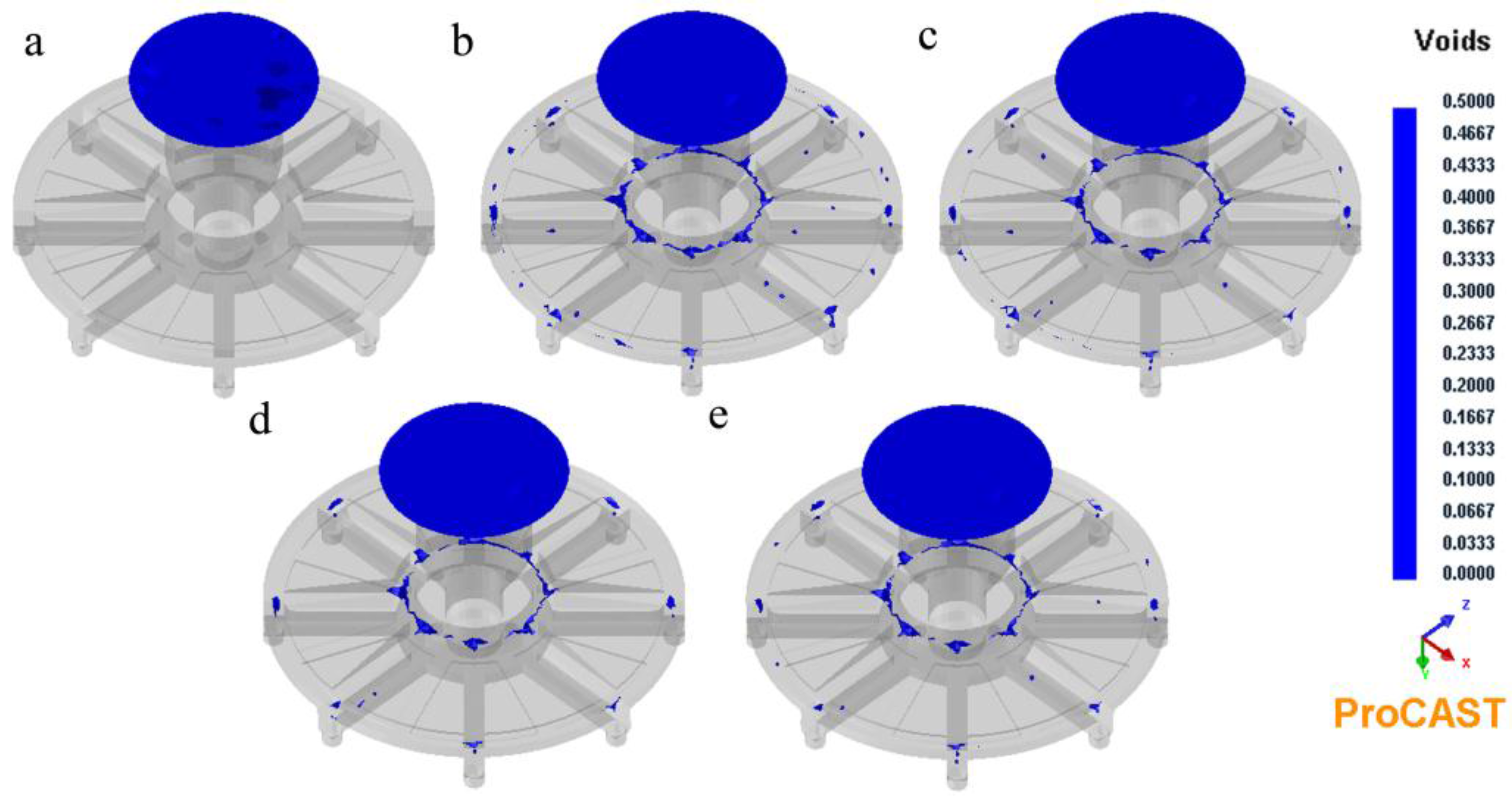
Shrinkage porosity is the result of failure of feeding to operate effectively. In this case, centrifugal force can effectively decrease shrinkage porosity; however, it would produce voids, which are caused by gas trapped in the liquid alloy. Figure 11 shows the voids of the full-size castings. The 10-mm-thick disk is the required component; hence, the voids in the rib and platform are acceptable. The simulation data show that a mold temperature of 600 °C and rotation speed of 200 rpm are the best choice for the full-size casting. Although it is only slightly better than the other three plans (Figure 11b–e), considering that there are some harmful effects not included in the simulation such as sand hoppers, this marginal advantage is still worth consideration.
Figure 11.
Predicted voids of full-size castings, (a–e) the same as the Figure 10.
Figure 11.
Predicted voids of full-size castings, (a–e) the same as the Figure 10.

As shown in Figure 12a, few pores are observed in the rib, and the surface of the disk is defect-free. Radiography revealed major internal defects present (Figure 12b). As shown in Figure 12c, some micro-porosity is also observed in the disk. The pores exhibit a round, smooth edge; hence, they are blowholes. At a mold temperature of 600 °C and rotation speed of 200 rpm, marginal shrinkage porosity and voids are observed in the simulation (Figure 10d and Figure 11d). We speculate that their presence is attributed to the fact that the permeability of the mold is not sufficient. There is an ideal condition for ProCAST, but not for the experiment. There is also an indication of shrinkage in the junction between the rib and the outer ring of the disk (Figure 12d), which is a hot spot because storage is present under it.
Figure 12.
X-ray nondestructive inspection results of full-size casting, (a) the grating casting and (b–d) correspond to b, c and d areas on (a), respectively.
Figure 12.
X-ray nondestructive inspection results of full-size casting, (a) the grating casting and (b–d) correspond to b, c and d areas on (a), respectively.

4. Conclusions
The mold-filling and solidification process of TiAl grating by centrifugal investment casting were simulated. The following principal conclusions were drawn from this study:
- (1)
- Gratings with diameters of 400 and 580 mm were successfully produced.
- (2)
- The casting parameters for the test casting were a pouring temperature of 1700 °C, a mold preheated temperature of 800 °C, and a rotation speed of 400 rpm.
- (3)
- The optimal casting parameters for full-size casting were a pouring temperature of 1700 °C, a mold preheated temperature of 600 °C, and a rotation speed of 200 rpm.
- (4)
- The specimens showed a typical fully lamellar microstructure, which exhibits finely segregated γ-grains. TiAl as-cast specimens exhibited a moderate mechanical property. At room temperature, the tensile strength and elongation were about 675 MPa and 1.7%, respectively.
Acknowledgments
This research was financially supported by the National Natural Science Foundation of China (No. 51001040) and the National Natural Science Foundation of China (No. 51371064).
Author Contributions
Yi Jia and Yuyong Chen conceived and designed the experiments; Yi Jia and Shulong Xiao performed the experiments; Yi Jia, Lijuan Xu and Jing Tian analyzed the data; Yi Jia wrote the paper.
Conflicts of Interest
The authors declare no conflict of interest.
References
- Kim, Y.W. Gamma-titanium aluminides: Their status and future. J. Miner. 1995, 47, 39–41. [Google Scholar] [CrossRef]
- Yamaguchi, M.; Inui, H.; Ito, K. High-temperature structural intermetallics. Acta Mater. 2000, 48, 307–322. [Google Scholar] [CrossRef]
- Varin, R.A.; Gao, Q. The effect of chromium on the microstructure and micromechanical properties of TiAl-base alloys. Mater. Manuf. Process. 1996, 11, 381–410. [Google Scholar] [CrossRef]
- Kuang, J.P.; Harding, R.A.; Campbell, J. Microstructures and properties of investment castings of γ-titanium aluminide. Mater. Sci. Eng. A 2002, 329, 31–37. [Google Scholar] [CrossRef]
- Gomes, F.; Barbosa, J.; Ribeiro, C.S. Induction melting of γ-TiAl in CaO crucibles. Intermetallics 2008, 16, 1292–1297. [Google Scholar] [CrossRef]
- Tsukihashi, F.; Tawara, E.; Hatta, T. Thermodynamics of calcium and oxygen in molten titanium and titanium-aluminum alloy. Metall. Mater. Trans. B 1996, 27, 967–972. [Google Scholar] [CrossRef]
- Barbosa, J.; Ribeiro, C.S.; Monteiro, A.C. Influence of superheating on casting of γ-TiAl. Intermetallics 2007, 15, 945–955. [Google Scholar] [CrossRef]
- Kuang, J.P.; Harding, R.A.; Campbell, J. Investigation into refractories as crucible and mould materials for melting and casting γ-TiAl alloys. Mater. Sci. Technol. 2000, 16, 1007–1016. [Google Scholar] [CrossRef]
- Jia, Q.; Cui, Y.Y.; Yang, R. Intensified interfacial reactions between γ-titanium aluminide and CaO stabilised ZrO2. Int. J. Cast Met. Res. 2004, 17, 23–27. [Google Scholar] [CrossRef]
- Nowak, R.; Lanata, T.; Sobczak, N.; Ricci, E.; Giuranno, D.; Novakovic, R.; Holland-Moritz, D.; Egry, I. Surface tension of γ-TiAl-based alloys. J. Mater. Sci. 2010, 45, 1993–2001. [Google Scholar] [CrossRef]
- Cui, R.J.; Gao, M.; Zhang, H.; Gong, S.K. Interactions between TiAl alloys and yttria refractory material in casting process. J. Mater. Process. Technol. 2010, 210, 1190–1196. [Google Scholar]
- Teodoro, O.; Barbosa, J.; Naia, M.D.; Moutinho, A.M.C. Effect of low level contamination on TiAl alloys studied by SIMS. Appl. Surf. Sci. 2004, 231, 854–858. [Google Scholar] [CrossRef] [Green Version]
- Sung, S.Y.; Kim, Y.J. Modeling of titanium aluminides turbo-charger casting. Intermetallics 2007, 15, 468–474. [Google Scholar] [CrossRef]
- Fu, P.X.; Kang, X.H.; Ma, Y.C.; Liu, K.; Li, D.Z.; Li, Y.Y. Centrifugal casting of TiAl exhaust valves. Intermetallics 2008, 16, 130–138. [Google Scholar] [CrossRef]
- Yang, R.; Cui, Y.Y.; Dong, L.M.; Jia, Q. Alloy development and shell mould casting of γ-TiAl. J. Mater. Process. Technol. 2003, 135, 179–188. [Google Scholar] [CrossRef]
© 2015 by the authors; licensee MDPI, Basel, Switzerland. This article is an open access article distributed under the terms and conditions of the Creative Commons Attribution license (http://creativecommons.org/licenses/by/4.0/).
Share and Cite
MDPI and ACS Style
Jia, Y.; Xiao, S.; Tian, J.; Xu, L.; Chen, Y. Modeling of TiAl Alloy Grating by Investment Casting. Metals 2015, 5, 2328-2339. https://doi.org/10.3390/met5042328
AMA Style
Jia Y, Xiao S, Tian J, Xu L, Chen Y. Modeling of TiAl Alloy Grating by Investment Casting. Metals. 2015; 5(4):2328-2339. https://doi.org/10.3390/met5042328
Chicago/Turabian StyleJia, Yi, Shulong Xiao, Jing Tian, Lijuan Xu, and Yuyong Chen. 2015. "Modeling of TiAl Alloy Grating by Investment Casting" Metals 5, no. 4: 2328-2339. https://doi.org/10.3390/met5042328