Article

Microstructures and Wear Performance of PTAW Deposited Ni-Based Coatings with Spherical Tungsten Carbide

1
School of Materials Science and Engineering, Dalian University of Technology, Dalian 116024, China
2
R & D Division of Shenyang Blower Works Group Corporation, Shenyang 110869, China
3
Department of Industrial Engineering, Texas Tech University, Lubbock, TX 79409-3061, USA
*
Author to whom correspondence should be addressed.
Metals 2015, 5(4), 1984-1996; https://doi.org/10.3390/met5041984
Submission received: 26 August 2015 / Revised: 26 September 2015 / Accepted: 20 October 2015 / Published: 26 October 2015
(This article belongs to the Special Issue Superalloys)

Abstract

:
The Ni-based coatings with different content of spherical tungsten carbide were deposited by plasma transfer arc welding (PTAW) method on 304 austenitic stainless steel sheets in this study. The microstructure and wear property of spherical tungsten carbide particle reinforced composite coatings were investigated by means of optical microscope, scanning electron microscope (SEM), X-ray diffraction (XRD), electron probe microanalysis (EPMA) and sliding wear test. It is shown that the fraction of spherical tungsten carbides has an important influence on microstructure of Ni-based overlay. The Ni40 overlay consists of γ-Ni dendrites with interdendritic Ni-based eutectics, borides and carbides improving the wear resistance. In the case of composite coatings with different content of tungsten carbide, many new phases are observed, such as Ni2W4C and NiW. In addition, there are a large number of irregular structures in composite coatings, such as acicular structure and irregular stripe organization. The results of sliding wear test indicate that the mass loss of coatings is influenced by the content of tungsten carbide. The mass loss decreases with the increase of tungsten carbide fraction. At high load, the abrasive resistance of composite coating with 60 wt. % tungsten carbide is improved about 50-fold compared to that of Ni40 overlay.

Graphical Abstract

1. Introduction

Ni-based alloy powders are widely used in industry for manufacturing wear and corrosion resistant coatings applied in aggressive service conditions such as tribological components in mineral processing, oil exploration, power industry and cement industry [1,2,3,4]. It has good wear resistance, high temperature stability, corrosion resistance, and good toughness. In order to reduce the overall maintenance costs and improve the wear resistance, it is a well-established fact that wear properties of materials can be improved by reinforcement of a metallic matrix by hard particles [3,5,6,7,8]. In the present work, the ceramic particle is spherical tungsten carbide. The abrasive wear resistance increases strongly with the addition of tungsten carbide into the metallic matrix. The Ni-based alloy powders also have excellent wettability to ceramic particles that promote cohesion, and a good self-melting property owing to the addition of boron and silicon that suppress the melting point by forming low melting point glasses that allow tungsten carbide to endure the deposition process without degradation, and excellent tribo-mechanical performance because of the addition of chromium. The additives act to enhance wear resistance by forming intermetallics or the solid solution strengthening of nickel dendrites. The resulting microstructures of Ni-based powders consist of nickel solid solution, chromium carbides, nickel and chromium borides, while the microstructures of Ni-based powders also comprise tungsten carbide made up of nickel solid solution, chromium carbides, spherical tungsten carbide and chromium borides.
At present, many methods for the synthesis of composite coatings have been reported, such as gas tungsten arc welding (GTAW), gas metal arc welding (GMAW), shielded metal arc welding (SMAW), submerged arc welding (SAW) and plasma transfer arc welding (PTAW). Compared with those methods, PTAW is a promising approach for depositing thick, metallurgical bonded coatings on a substrate. It offers a unique heat source for surface modification technology along with enormous potentials: low cost, high heat input, high efficiency, no need for surface pretreatment, easy operation, and synchronous powder-feeding mechanism [9,10].

2. Experimental Section

The Ni-based coatings with spherical tungsten carbide were deposited by the plasma transferred arc welding (PTAW) method on 304 austenitic stainless steel sheets. The powder was a mixture of Ni40 alloy powder and spherical tungsten carbide reinforcement particles. The morphology of the original alloy powdersisshown in Figure 1. The Ni40 alloy powder size ranges from 45 to 150 µm, whereas the tungsten carbide powder ranges from 45 to 180 µm. The average composition of Ni40 was shown in Table 1. In order to reduce the thermal stress and crack tendency during the welding process, the 304 austenitic stainless steel sheets were pre-heated under 400 °C for 2 h. The substrate was polished by sand paper and cleaned with anhydrous ethanol to obtain good interface bonding between the substrate and overlay. The welding powder was baked to improve the flowability under 150 °C for 2 h in electric oven. The detailed parameters of welding process were shown in Table 2. According to the different content (0 wt. %, 30 wt. %, 45 wt. %, 60 wt. %) of spherical tungsten carbide, the as-deposited coatings were marked as sample A, B, C and D, respectively.
Figure 1. The SEM images of spherical tungsten carbides (a) and Ni40 alloy powder (b).
Metals 05 01984 g001
Table 1. Chemical composition of the Ni40 powder.
ElementCSiCrMnFeBNi
Weight (wt. %)0.323.297.530.0041.091.70Bal
Table 2. Welding parameters of the plasma transfer arc welding (PTAW).
ParameterSample ASample BSample CSample D
Content of tungsten carbide (wt. %)0304560
Current (A)140140140140
Voltage (V)30303030
Torch oscillation width (mm)20202020
Shaking frequency(c/min)20202020
Travel speed (mm/min)40404040
Shielding gas flow rate (L/min)10101010
Powder feed rate (g/min)20202020
Preheat temperature (K)673673673673
The morphology and structure of as-deposited coatings were characterized by optical microscope (Nikon-MA100, Nikon, Tokyo, Japan), scanning electron microscopy (ZEISS EVO 18, ZEISS, Jena, Germany), and X-ray diffraction (Jin-Island XRD-6000, Shimadzu, Kyoto, Japan), respectively. The distribution of the elements in each structure that appeared in the coatings was analyzed by using the electron probe microanalysis (EPMA-1600, Shimadzu, Kyoto, Japan). Wear tests on the coated surfaces were carried out at room temperature in a tribometer (MMS-2A, Yihua, Jinan, China). A two test load of 50 N and 150 N were applied. Testing parameters were conducted at a rotational speed of 90 rpm and a sliding time of 60 min. Wear characteristic was done by mass loss of specimens. Qualitative analysis of the predominant wear mechanism was investigated by SEM.

3. Results and Discussion

3.1. Structure and Morphology Analysis

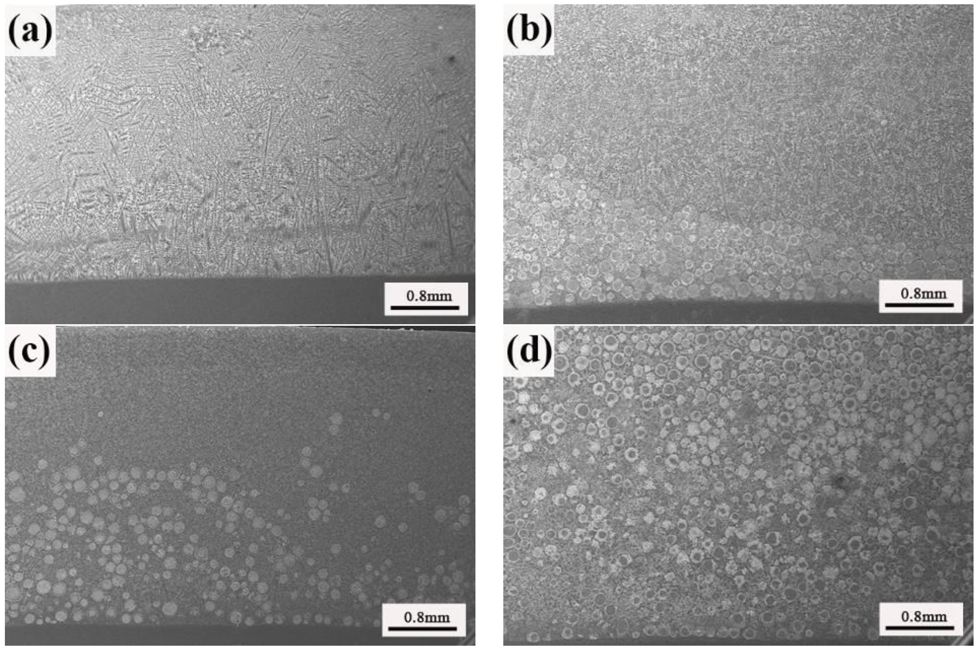
Figure 2 shows the cross-section micrograph of different coatings. It can be seen that the coatings deposited by PTAW exhibit cohesive, metallurgical and defect-free properties, and the thickness is in the range of 3~5 mm. The micrograph of sample A without tungsten carbide reveals continuous and sound interfaces between the substrate and the infiltrated composite layer, and primary dendritic structure with interdendritic phases is observed, as shown in Figure 2a. When spherical tungsten carbide is added to the Ni40 alloy, the tungsten carbides are depleted in vicinity of surface. The spherical tungsten carbide appears to be more densely packed near the fusion line area, which is related to higher melting point and density compared to the nickel based alloy. With the increase of tungsten carbides, the region at the surface was depleted of carbide reduces. The circular zones denuded of primary tungsten carbide particles are present in sample C. The circular regions denuded of primary carbide are not empty space, but a mixture of matrix and complex carbide phases [11]. Figure 2d illustrates the microstructure of sample D with 60 wt. % spherical tungsten carbide. The particles appear to be homogenously distributed through the alloy coating thickness, and there isa high dissolution degree for tungsten carbide. There are only a few examples of tungsten carbide maintaining original morphology, because itis difficult to distinguish individual spherical tungsten carbide.
Figure 2. The SEM cross-section images of different samples (a) sample A; (b) sample B; (c) sample C; (d) sample D.
Metals 05 01984 g002
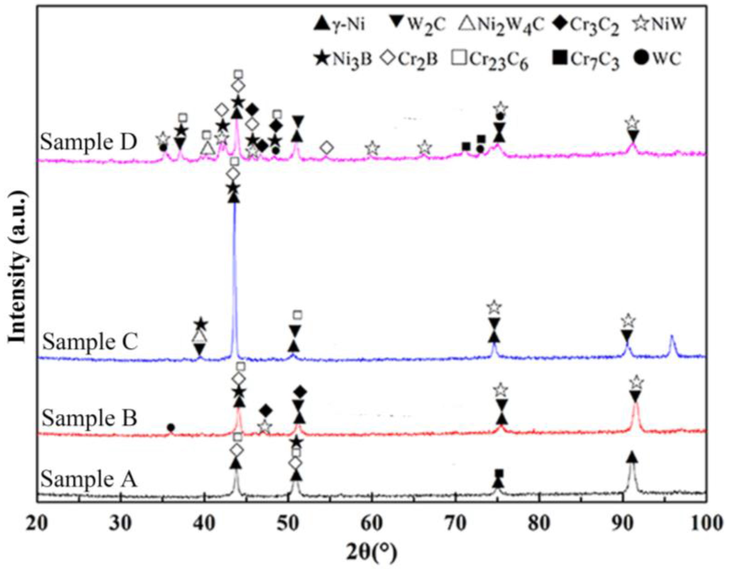
Figure 3 shows XRD patterns of the coatings with different tungsten carbide content. A mixture of chromium carbide, chromium boride, and nickel boride is identified in all coatings. When tungsten carbides added in Ni40 overlay, some new phase structures containing mainly Ni2W4C and NiW are observed in composite coatings, which are attributed to the reaction between dissolved tungsten carbide and the matrix elements. With the increase of tungsten carbide fraction, the intensity of WC phase increases, and more phases appear because of more dissolved tungsten carbides.
In order to further investigate the microstructure of coatings, higher SEM magnification and EPMA are carried out. 
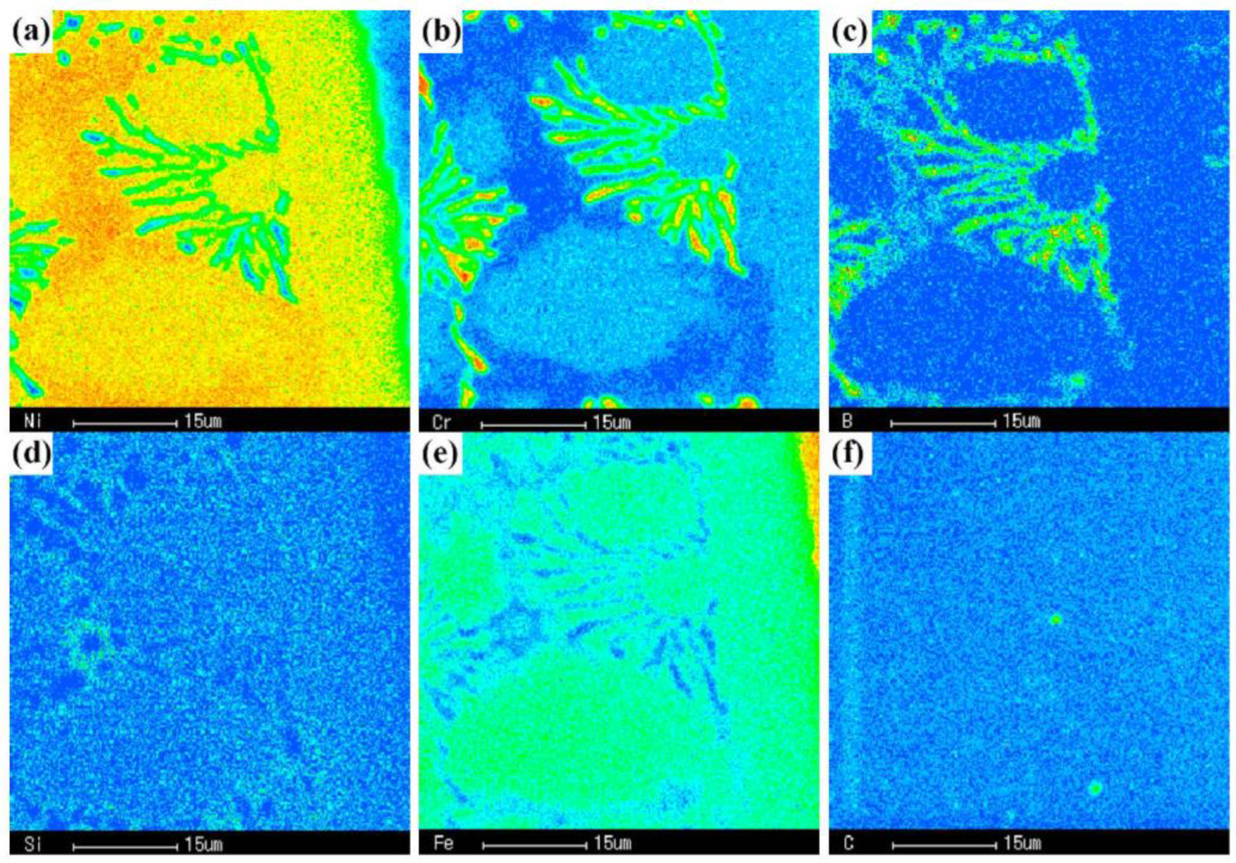
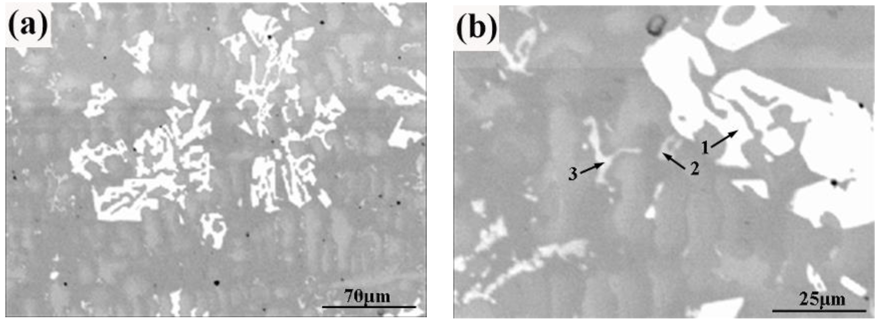
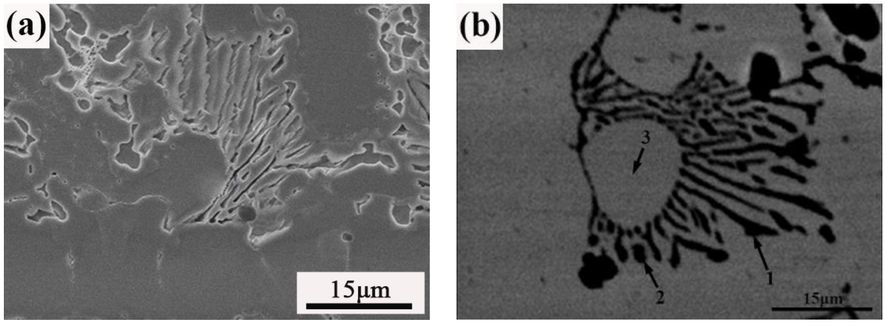
Figure 4 shows the cross-section images of sample A. It can be seen that this region consists of high volume fraction of herringbone structures. As shown in Figure 5, the herringbone structures contain three different types of structure. The thread-like phase (1) and granular phase (2) contain higher levels of B and Cr; while the matrix (3) is mainly Ni and Fe, shown in Table 3. Although phase 1 and phase 2 mainly contain the elements of B and Cr, the molar ratio is different. The herringbone structures could be identified to be Cr2B, which is a eutectic solidification product in Cr–B binary phase diagram. The invariant transformation is L → Cr2B + α(Cr) + γ(Ni), and may occur at 1495 K. In addition, α-Cr could not be detected as a separate phase, possibly due to the submicron size and because itprecipitates along with Cr2B [12].
Figure 3. XRD patterns of the coatings.
Metals 05 01984 g003
Figure 4. SEM (a) and backscatter electron (BSE) (b) images of the herringbone structure of sample A.
Metals 05 01984 g004
Table 3. The electron probe microanalysis (EPMA) results of points on Figure 4b. Composition is shown in %.
ElementNiCrBSiFeC
14.50036.49850.0580.2525.8642.827
210.54927.07050.9390.6077.7283.106
340.99811.5020.0002.12937.5647.807
Figure 5. Elemental mapping of the herringbone structure of sample A (a) Ni; (b) Cr; (c) B; (d) Si; (e) Fe; (f) C.
Metals 05 01984 g005
Figure 6 shows the backscatter electron (BSE) mode of sample B. It can be found that the block phase (1) is the brightest and composed mainly of Ni, Cr, C, and W. The molar ratio of C and W is approximate 1:1. The matrix phase (3) mainly contains Ni and B. It also can be found that a bright flocculent structure (2) appears in the matrix, and it consists of Ni, Cr, B, C and W, as shown in Table 4. The reason why some structures contained high W is that some tungsten carbides are dissolved at high temperature.
Figure 6. BSE images of the sample B (a) low-magnification image; (b) high-manification image.
Metals 05 01984 g006
Table 4. The EPMA results of points on Figure 6b. Composition is shown in %.
ElementNiCrBSiFeCW
129.19920.2940.0008.8593.66118.59819.389
212.72634.86729.9120.0007.1747.4917.830
360.8294.90015.4870.7829.0828.7060.215
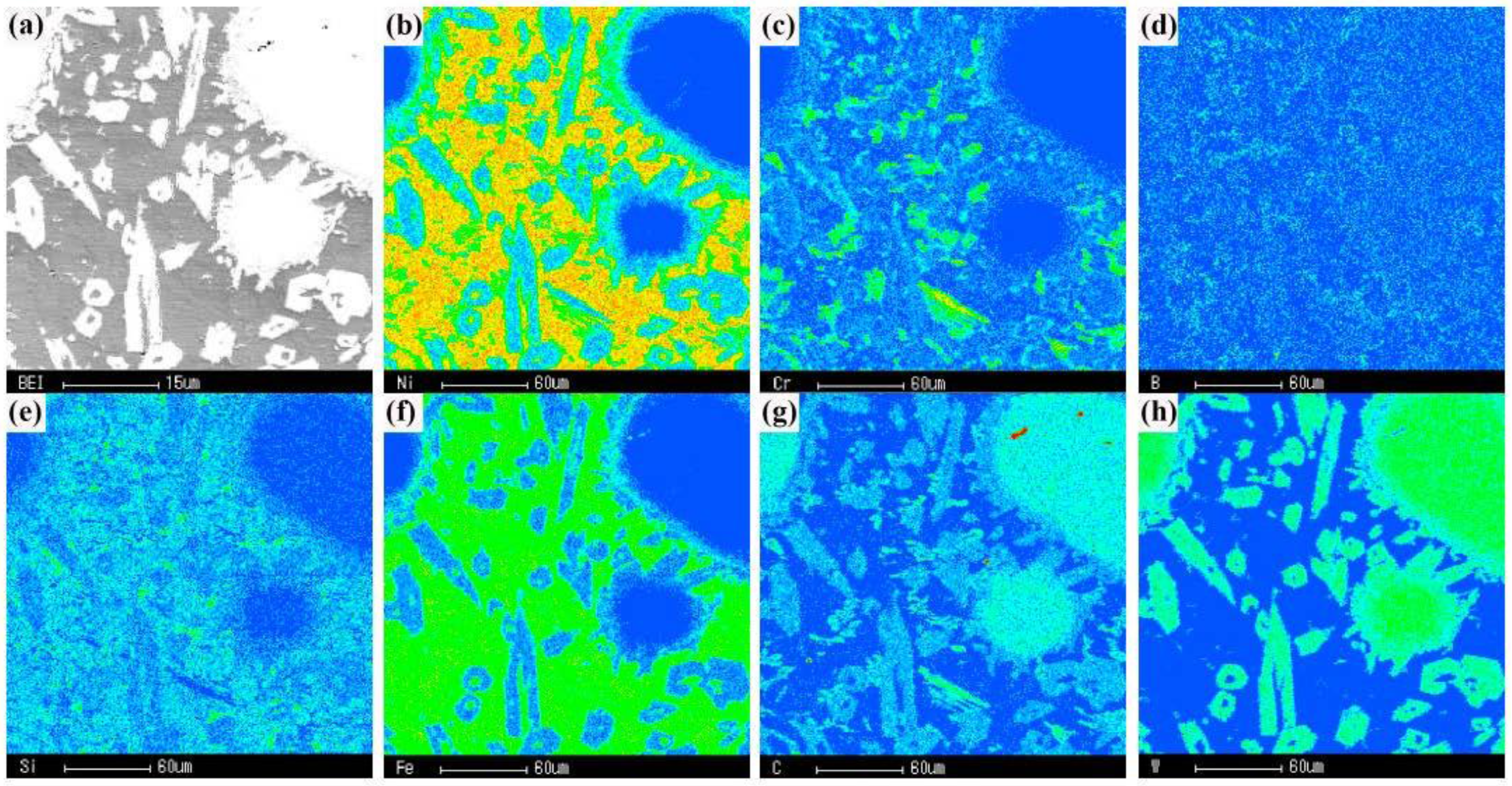
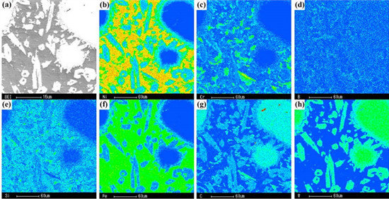
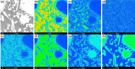
The element distribution of sample C measured by EMPA is shown in Figure 7. The W and C are preferentially found in acicular structures, while Ni and Fe are mainly present in the matrix phase. Since the carbide is exposed to high temperatures of the plasma, the tungsten carbide particle may experience some degree of dissolution in the melt. W and C elements accumulate and react with the matrix elements. Then, the acicular tungsten carbides are formed, which is associated with the contact interface. In addition, the flocculent structure at the edge of acicular tungsten carbide is rich in Cr, B, Si, C and Fe, which is the mixture of carbides and borides.
Figure 7. Elemental mapping of the acicular constituent of sample C (a) BEI; (b) Ni; (c) Cr; (d) B; (e) Si; (f) Fe; (g) C; (h) W.
Metals 05 01984 g007
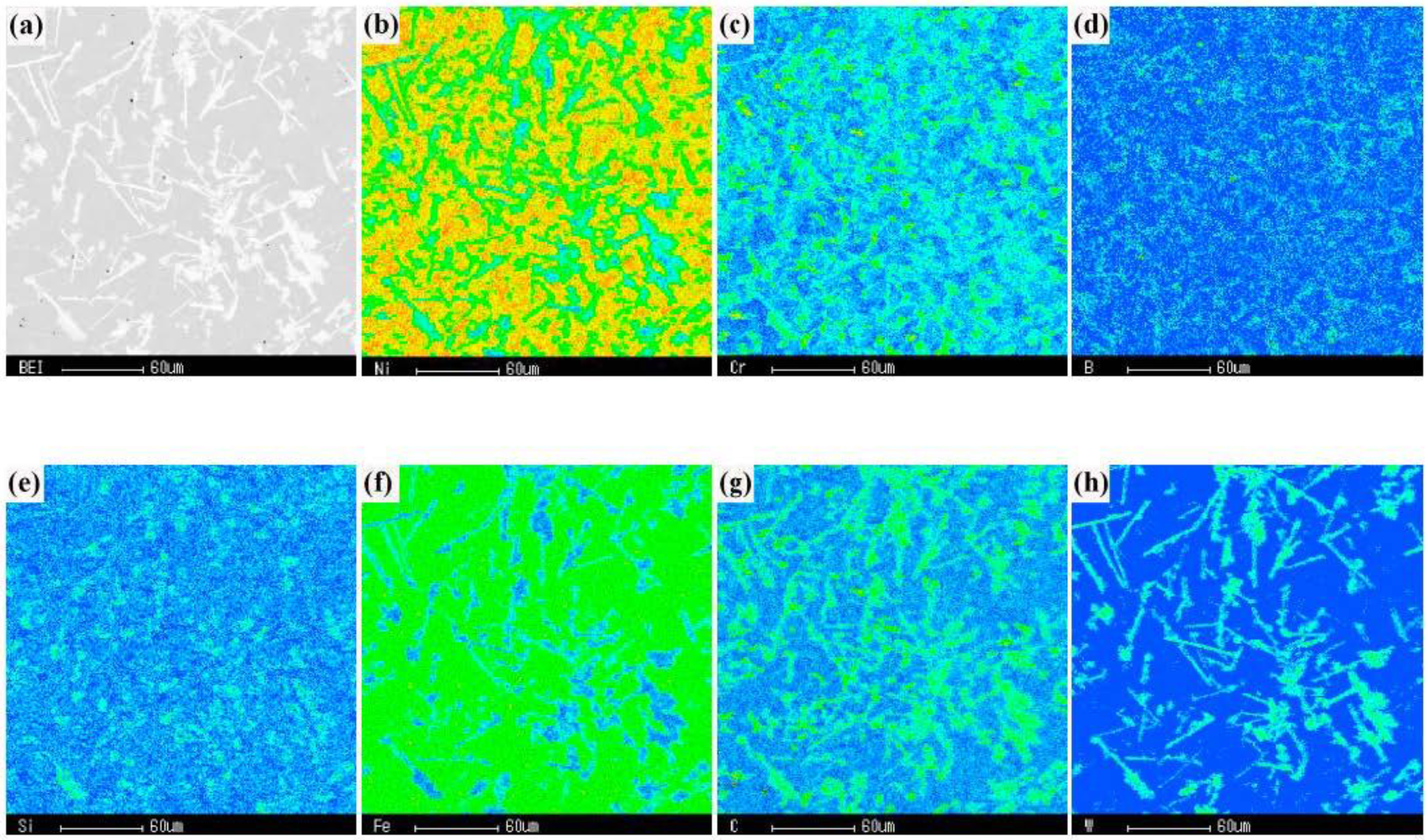
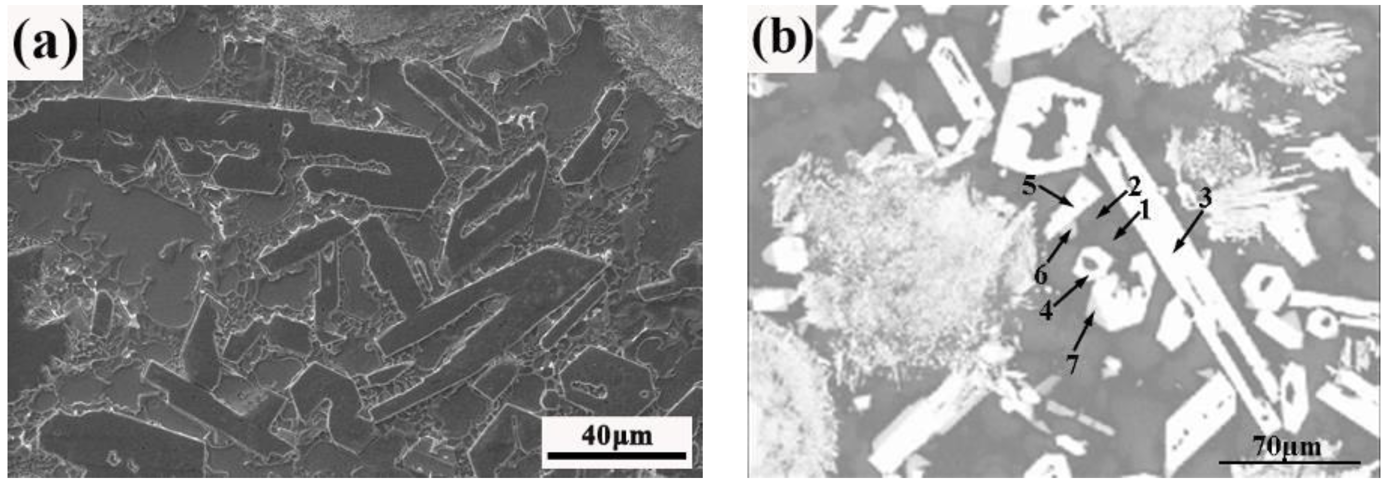
The irregular strip and block structures are found in sample D, as shown in Figure 8 and Figure 9. To identify the constituents of the structure, a quantitative point analysis for electron probe was adopted. The results are shown in Table 5. It can be found that there are three different types of structures that appear in the coating. For the first type, there are two matrix phases. The phase (1) contains higher levels of W, Cr and Si, while the phase (2) has more B. The second type, phases (3), (4) and (5) are the brightest structure with different morphologies. According to EPMA results, the structure maybe composed of complex composition such as (W10CrNi4)xCy. The last structure is phases (6) and (7), which are found at the edge of the bright phase. Due to the higher amounts of Ni and less W, the bright phase is less than the second type. The structures formed with different morphology are due to the eutectic tungsten carbide not being stable when deposited by PTAW. The secondary carbides are tungsten based and they originate from the surface of the primary carbide [11].
Figure 8. SEM (a) and BSE (b) images of the sample D.
Metals 05 01984 g008
Figure 9. Elemental mapping of the acicular constituent of sample D (a) BEI; (b) Ni; (c) Cr; (d) B; (e) Si; (f) Fe; (g) C; (h) W.
Metals 05 01984 g009
Table 5. The EPMA results of points on Figure 8b. Composition is shown in %.
ElementNiCrBSiFeCW
180.2237.2260.0001.4602.7925.4382.860
272.9974.78314.0530.9811.6224.7350.829
320.1005.3951.6120.2970.37919.70152.516
421.7295.0351.6820.3270.50719.30951.411
521.2545.8883.1070.3620.40319.58749.397
634.35519.3280.0002.9970.52316.37226.424
732.76715.1220.0002.5210.48216.53532.572

3.2. Sliding Wear Property

Most as-deposited coatings are devoid of tungsten carbide near the surface. In order to investigatethe effect of tungsten carbide fraction on wear property, all samples are ground down by 1 mm. Sliding wear tests with different load were carried out at room temperature. Figure 10 shows the mass loss of coatings as a function of load and the content of tungsten carbide. It can been clearly seen that the abrasive wear resistance is related to the fraction of tungsten carbide and test load, and mass loss decreases with the content of tungsten carbide while it increases with the test load. At high load, the mass loss is about 0.03 g when not adding the tungsten carbide. As the content of tungsten carbide increases, the wear resistance of the coating is improved significantly. When the content of tungsten carbide increases to 60 wt. %, the mass loss is decreased to 0.0006 g, indicating that the wear resistance is improved about 50 times compared to the Ni40 overlay. At low load, the change rule of the abrasive resistance is similar to that of the high load. In the case of the Ni40 alloy overlay, the mass loss under high load decreases, which could be attributed to the formation of Ni-based oxide layers on the sliding surfaces [1].
Figure 10. Mass loss of the coatings with different test load.
Metals 05 01984 g010
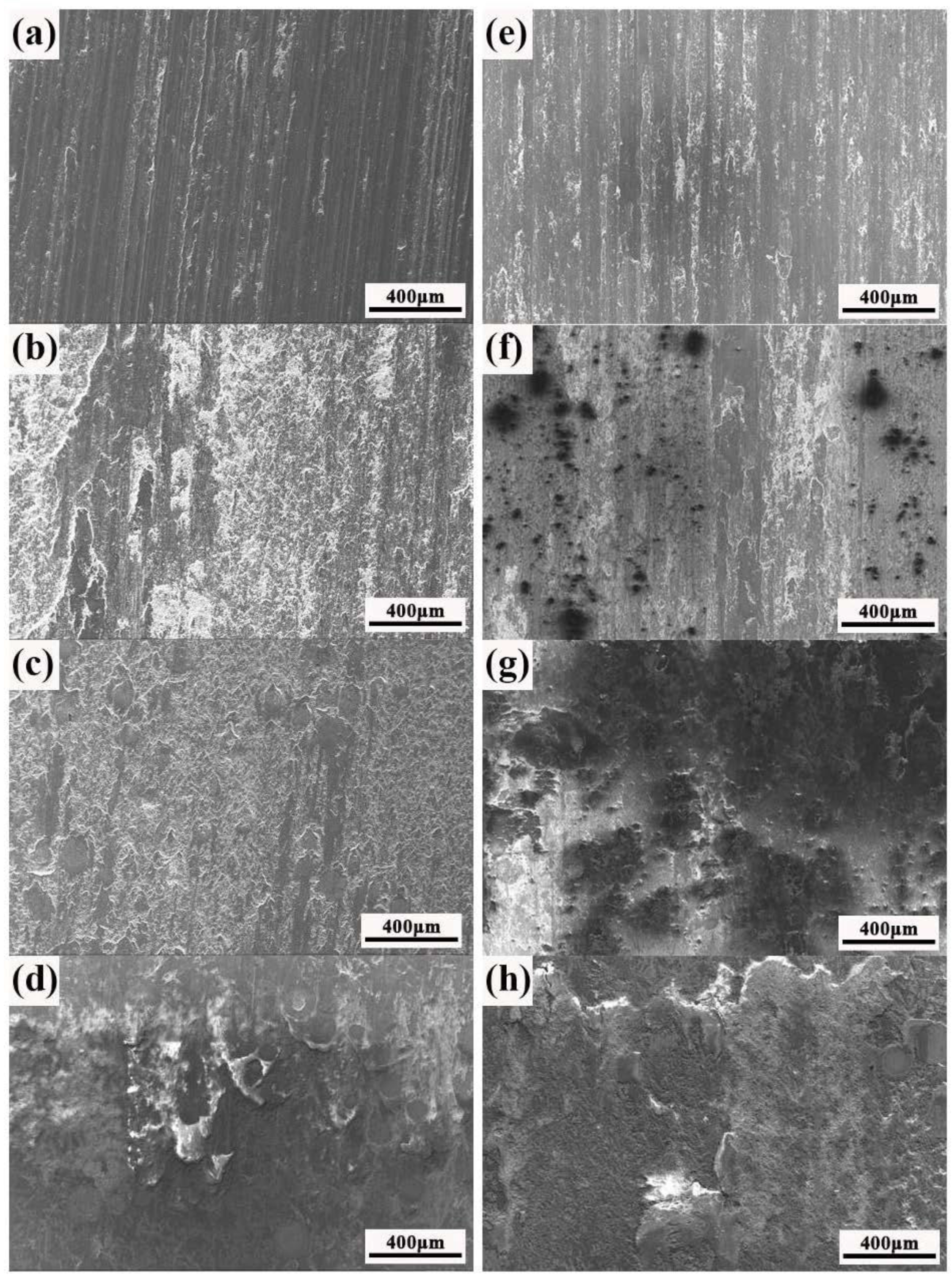
In general, abrasive wear resistance is not an intrinsic property of materials but depends on the tribological system. There are different wear mechanisms for the abrasive wear of the WC/Ni layer, such as micro-cutting, plastic deformation due to the ploughing action, and fracture of hard-phase debris in the matrix materials [13]. However, micro-cutting is considered as the dominant mechanism, ultimately controlling the wear [7,13]. In order to identify the wear mechanisms taking place in the different test conditions, the worn surfaces by scanning electron microscopy (SEM) were examined, as shown in Figure 11. Since the wear track of sample A has a rough morphology with evidence of abrasion and ploughing marks, the micro-cutting and ploughing are the main abrasive wear mechanisms for sample A. When Ni40 matrix materials are mixed with hard tungsten carbides, the observed worn surfaces are smooth, and only mild abrasion with delaminated portion is observed. The interlocked tungsten carbide particles are observed for sample D. On the one hand, the interlocked nature of tungsten carbide particles provides a significant barrier to the cutting and the degree of the micro-cutting is greatly limited. It is primarily responsible for excellent abrasive wear resistance of composite coatings because it changes the load carrying capacity of the composite structure [5,6]. On the other hand, during the wear process, the wear debris starts to erode the softer matrix and then collides with the hard tungsten carbide particles. The hard phase prevents the wear debris from micro-cutting the surface by smashing and breaking them up and causing them to lose their cutting function. Then, the abrasive wear resistance of the resulted composite coatings is greatly enhanced, and is directly proportional to the amount of carbide presented.
Figure 11. SEM images of worn surfaces with different load. High test load: (a) sample A; (b) sample B; (c) sample C; (d) sample D. Low test load: (e) sample A; (f) sample B; (g) sample C; (h) sample D.
Metals 05 01984 g011
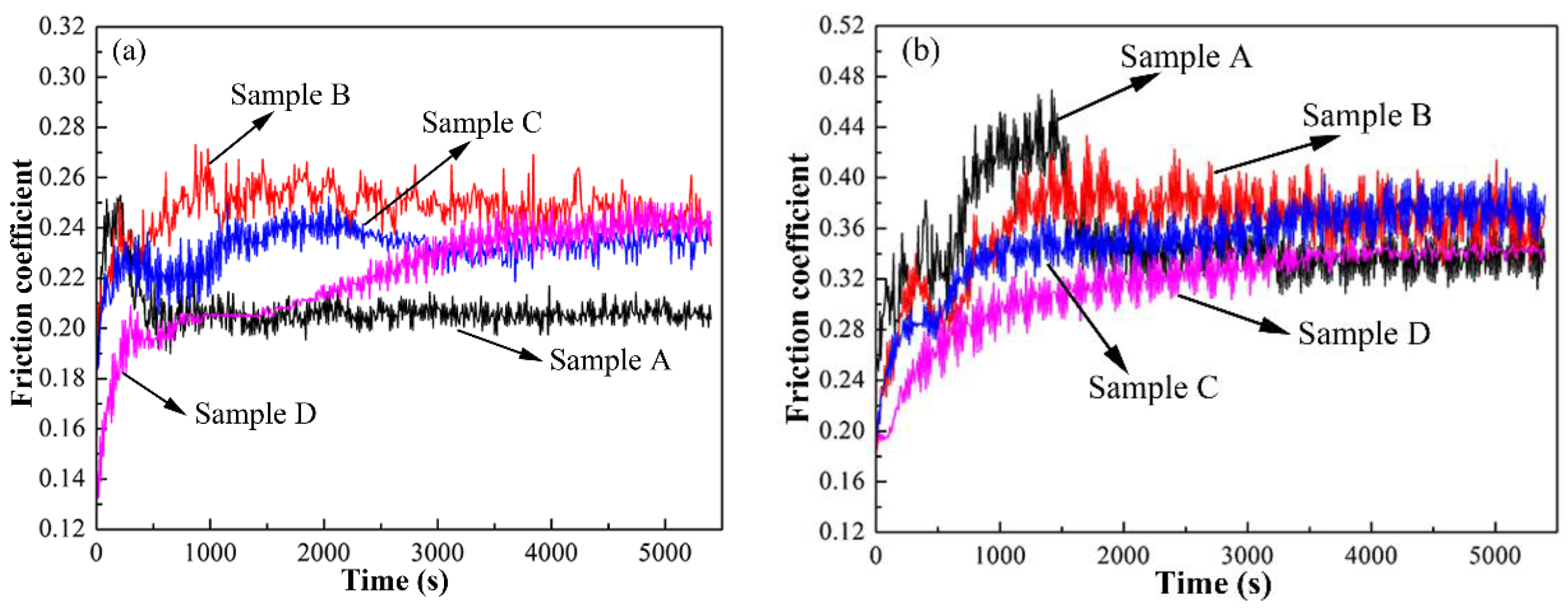
Figure 12 shows the friction coefficient of coatings with different test load. It can be seen that there are two obvious stages which calls running-in and steady state appeared during the wear experiment. The friction coefficient (COF) is strongly dependent upon the testing load and the content of tungsten carbides. Under the condition of high load (Figure 12a), the running-in stage lasts about 1400s for all coatings and then entered steady state. The friction coefficient of sample A exhibits a peak trend. The friction coefficient first increases rapidly. With the increase of wear time, the oxide layer is formed, and the friction coefficient decreases until steady stage. The severe wear of samples B–D during running-in period results from the projection of hard asperities and accumulation of the wear debris which causes abrasion and plough on the sliding surfaces [1,8,14]. For sample D with 60 wt. % spherical tungsten carbide, the value of friction coefficient (COF) increases at the early stage of steady state. Although the content of tungsten carbide were different, the friction coefficient (COF) is similar and ranges from 0.23 to 0.25. In the case of low load (Figure 12b), the running-in stage lasts about 1500 s for all coatings. When the steady state is entered, the value of friction coefficient (COF) varies from 0.34 to 0.38. The value of friction coefficient (COF) under low load is higher than that of high load, and the experimental process is more stable. Due to the low temperature of wear surface under low load, bigger plastic deformation resistance of the friction pair is formed and friction resistance increases, leading to a higher friction coefficient.
Figure 12. Friction coefficient of coatings with different load. (a) High load; (b) Low load.
Metals 05 01984 g012

4. Conclusions

Ni40 alloys reinforced with spherical tungsten carbides are successfully produced by plasma transferred arc welding on 304 austenitic stainless steel sheets. The fraction of spherical tungsten carbide adding in Ni40 alloy layer has an important influence on microstructure. For the Ni40 overlay, it consists of a high volume fraction of the herringbone near the fusion line area. When the spherical tungsten carbide adds to the Ni40 alloy, the spherical tungsten carbide appears to be more densely packed near the fusion line area. Moreover, there are a large number of irregular structures observed in composite coatings, such as acicular structure and irregular stripe organization. The wear resistance of composite coatings is related to the fraction of spherical tungsten carbide and test load. The mass loss decreases with the increase of spherical tungsten carbide, and shows a high value under high load.

Acknowledgments

This work was carried out with the financial support of the National Key Basic Research and Development Program (No. 2011CB013402), Liaoning Natural Science Foundation (No. 2014028002), Liaoning Science and Technology Innovation Project (No. 201303002), SBW-DUT Key Research and Development Program, the Fundamental Research Funds for the Central Universities.

Author Contributions

D.W. Deng led the research activity, carried out some of the experimental work and edited the manuscript. L. Zhang, T.T. Niu, H.Y. Liu and H.C. Zhang carried out most of the experimental work.

Conflicts of Interest

The authors declare no conflict of interest.

References

  1. Katsich, C.; Badisch, E. Effect of carbide degradation in a Ni-based hardfacing under abrasive and combined impact/abrasive conditions. Surf. Coat. Technol. 2011, 206, 1062–1068. [Google Scholar] [CrossRef]
  2. Kesavan, D.; Kamaraj, M. The microstructure and high temperature wear performance of a nickel base hardfaced coating. Surf. Coat. Technol. 2010, 204, 4034–4043. [Google Scholar] [CrossRef]
  3. Van Acker, K.; Vanhoyweghen, D.; Persoons, R.; Vangrunderbeek, J. Influence of tungsten carbide particle size and distribution on the wear resistance of laser clad WC/NI coatings. Wear 2005, 258, 194–202. [Google Scholar] [CrossRef]
  4. Gahr, K.-H.Z. Microstructure and mechanical properties of materials. In Microstructure and Wear of Materials; Tribology Series 10; Elsevier: Amsterdam, The Netherlands, 1987; Volume 10, pp. 8–47. [Google Scholar]
  5. Badisch, E.; Kirchagassner, M. Influence of welding parameters on microstructure and wear behaviour of a typical nicrbsi hardfacing alloy reinforced with tungsten carbide. Surf. Coat. Technol. 2008, 202, 6016–6022. [Google Scholar] [CrossRef]
  6. Celik, O.N. Microstructure and wear properties of WC particle reinforced composite coating on Ti6Al4V alloy produced by the plasma transferred arc method. Appl. Surf. Sci. 2013, 274, 334–340. [Google Scholar] [CrossRef]
  7. Huang, S.W.; Samandi, M.; Brandt, A. Abrasive wear performance and microstructure of laser clad WC/Ni layers. Wear 2004, 256, 1095–1105. [Google Scholar] [CrossRef]
  8. Liyanage, T.; Fisher, G.; Gerlich, A.P. Microstructures and abrasive wear performance of PTAW deposited Ni-WC overlays using different Ni-alloy chemistries. Wear 2012, 274, 345–354. [Google Scholar] [CrossRef]
  9. Huang, Z.Y.; Hou, Q.Y.; Wang, P. Microstructure and properties of Cr3C2-modified nickel-based alloy coating deposited by plasma transferred arc process. Surf. Coat. Technol. 2008, 202, 2993–2999. [Google Scholar] [CrossRef]
  10. Liyanage, T.; Fisher, G.; Gerlich, A.P. Influence of alloy chemistry on microstructure and properties in NiCrBSi overlay coatings deposited by plasma transferred arc welding (PTAW). Surf. Coat. Technol. 2010, 205, 759–765. [Google Scholar] [CrossRef]
  11. Wolfe, T.B.; Henein, H. Predicting Homogeneity of WC-Based Metal Matrix Composites Deposited by plasma Transferred Arc Welding. In Proceedings of the 12th International Conference on Modeling of Casting, Welding, and Advanced Solidification Processes, Vancouver, BC, Canada, 7–14 June 2009; pp. 585–599.
  12. Sudha, C.; Shankar, P.; Rao, R.S.; Thirumurugesan, R.; Vijayalakshmi, M.; Raj, B. Microchemical and microstructural studies in a PTA weld overlay of Ni–Cr–Si–B alloy on AISI 304L stainless steel. Surf. Coat. Technol. 2008, 202, 2103–2112. [Google Scholar] [CrossRef]
  13. Wang, H.; Xia, W.M.; Jin, Y.S. A study on abrasive resistance of Ni-based coatings with a WC hard phase. Wear 1996, 195, 47–52. [Google Scholar] [CrossRef]
  14. Deng, D.W.; Xia, H.F.; Ge, Y.L. Influence of welding currents on microstructure and microhardness of Ni45 alloy reinforced with spherical tungsten carbides (40 mass %) by plasma transferred arc welding. Mater. Trans. 2013, 54, 2144–2150. [Google Scholar] [CrossRef]

