Corrosion Protection of Electrically Conductive Surfaces

Precision Engineering Laboratory, Ostwestfalen-Lippe University of Applied Sciences, Liebigstrasse 87, 32657 Lemgo, Germany
*
Author to whom correspondence should be addressed.
Metals 2012, 2(4), 450-477; https://doi.org/10.3390/met2040450
Submission received: 19 June 2012
/
Revised: 10 September 2012
/
Accepted: 1 November 2012
/
Published: 15 November 2012
(This article belongs to the Special Issue Advanced Corrosion Resistant Alloys for Energy Production, Storage, and Transportation Systems)
Abstract
:The basic function of the electrically conductive surface of electrical contacts is electrical conduction. The electrical conductivity of contact materials can be largely reduced by corrosion and in order to avoid corrosion, protective coatings must be used. Another phenomenon that leads to increasing contact resistance is fretting corrosion. Fretting corrosion is the degradation mechanism of surface material, which causes increasing contact resistance. Fretting corrosion occurs when there is a relative movement between electrical contacts with surfaces of ignoble metal. Avoiding fretting corrosion is therefore extremely challenging in electronic devices with pluggable electrical connections. Gold is one of the most commonly used noble plating materials for high performance electrical contacts because of its high corrosion resistance and its good and stable electrical behavior. The authors have investigated different ways to minimize the consumption of gold for electrical contacts and to improve the performance of gold plating. Other plating materials often used for corrosion protection of electrically conductive surfaces are tin, nickel, silver and palladium. This paper will deal with properties and new research results of different plating materials in addition to other means used for corrosion protection of electrically conductive surfaces and the testing of corrosion resistance of electrically conductive surfaces.
Keywords:
corrosion; fretting; wear; plating materials; passivation; gold; nanoparticles; electrical contacts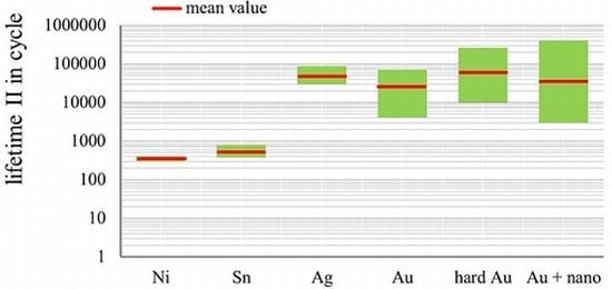
1. Introduction
Electrical and electronic components and devices are usually packed in gastight housings. The only parts exposed to the atmosphere are terminals with their electrical contacts. The basic function of electrically conductive surfaces of electrical contacts is electrical conduction. Copper and copper alloys are widely used base materials for electrical contacts.
1.1. Corrosion
Copper and copper alloys are materials, which are prone to corrosion. The electrical conductivity of contact materials can be largely reduced by corrosion and in order to avoid corrosion, protective surfaces must be used. There are basically two groups of materials, which can be employed for corrosion protection of electrically conductive surfaces. The first group includes noble metals such as gold, silver and palladium. The second group comprises of corrosion resistant so-called passive metals such as tin and nickel. These metals are basically ignoble and they derive their corrosion resistance from the presence of a thin oxide film on the surface, called the passive film, which acts as a protective barrier between the metal and its environment. The passive film inhibits deeper corrosion, and is usually an oxide or nitride with a thickness of nanometers [1]. Corrosion protection of passive metals is limited to certain conditions, which are applied to many working environments of electrical contacts.
Nevertheless, not all the passive metals or alloys are suitable for corrosion protection of electrically conductive surfaces. In the case of aluminum and aluminum alloys, the passive films are too thick and too stable. They are therefore highly electrically resistant. A good electrical contact can only be realized by destroying the passive film either by high mechanical pressure or by a strong electrical field. These conditions are often not available, especially in microelectronics.
Among the plating materials gold has the highest standard electrode potential of 1.38 Volt [2] and is therefore the noble material used for plating with the highest corrosion resistance. A perfect coating with gold is not problematic regarding corrosion. Due to the high cost of material the plating of gold is often so thin that the final coating is not free of pores. These pores are the cause of corrosion of electrically conductive surfaces with protective coatings. Therefore one of the goals of the optimization of gold coating is minimization of both the number and the size of pores of gold coating with the thinnest possible plating. This is also one of objectives of our investigation.
The passive plating materials such as tin and nickel can also have problems with the pores on the plating and the porosity can also be decreased by increasing the thickness of the plating. In the case of the ignoble metals the main limiting factors for the thickness of coating are not mainly the consumption of plating materials and processing time but other performance factors such as mating forces or ductility of the coatings. The porosity of coatings can be largely reduced by optimization of plating processes. Passivation is another additional measure which can be employed to close the pores for a limited period of time.
The corrosion behaviors of metals to different media can differ. The most common corrosive media for electronics are hydrogen sulfide (H2S), sulfur dioxide (SO2), chlorine (Cl2), nitrogen dioxide (NO2), ammonia (NH3), air (oxygen) and salt fog. Corrosion behaviors of electrically conductive surfaces are therefore tested in the atmosphere with one or several of these media, often at elevated temperature, which accelerates the corrosion process. Before, during and after the tests the electrical contact resistance is measured. The relation of contact resistance after and before the tests is usually used to describe the degree of corrosion.
Pure gold is resistant to almost all these media. In the case of chlorine it depends on the concentration of chlorine in the atmosphere and duration of the test. Corrosion can be observed at high concentration of chlorine and after an accelerated corrosion test of 21 days. The corrosion resistance of gold becomes slightly lower, when hard gold alloys such as AuNi or AuCo are used. The critical media for gold alloys are hydrogen sulfide (H2S), sulfur dioxide (SO2), chlorine (Cl2) and air (oxygen). A marked increase of corrosion due to the porosity of the coating was observed, when a very thin gold coating was used. A similar corrosion protection like gold alloy can be provided by tin, silver and palladium. These plating materials have quite different physical, chemical and technological properties and the availability and the cost of plating materials differ immensely. Tin is used because of the very slow growth of its oxide layer and due to the fact that its oxide film remains very thin under many technically relevant conditions and can be mechanically broken by a low contact force. Good electrical conduction can therefore easily take place. The critical media for tin, depending on the modification of tin, are sulfur dioxide (SO2), chlorine (Cl2) and salt fog. Silver has a high standard electrode potential of 0.8 Volt and is therefore regarded as a noble metal. Palladium has a standard electrode potential of 0.915 Volt and is regarded as a noble metal. Their corrosion resistance is almost as high as gold alloys. The critical media for silver are hydrogen sulfide (H2S), chlorine (Cl2), nitrogen dioxide (NO2) and salt fog and hydrogen sulfide (H2S), sulfur dioxide (SO2) and chlorine (Cl2) for palladium. For electrically conductive surfaces coatings of palladium nickel alloys are generally used. Nickel coating does not provide very good corrosion protection for electrically conductive surfaces. It is normally only used for high temperature cases, because of its high thermal resistance.
Table 1 provides an overview of corrosion resistances of the most common used coating materials for electrically conductive surfaces and the base material copper [2,3,4].

| Material | H2S | SO2 | Cl2/4 d | NO2 | NH3 | air/120 °C | Salt fog |
|---|---|---|---|---|---|---|---|
| Au, 3 µm | 1 | 1 | 2 | 1 | 1 | 1 | 1 |
| AuCo1, 3 µm | 1 | 1 | 3 | 1 | 1 | 3 | 1 |
| AuNi10, 3 µm | 2 | 2 | 1 | 1 | 1 | 2 | 1 |
| Au, 0.2 µm | 1 | 3 | 3 | 3 | 1 | 3 | 2 |
| Ni, 3 µm/Au, 1 µm | 3 | 1 | 3 | 1 | 1 | 1 | 1 |
| Ni, 3 µm/Au, 3 µm | 1 | 1 | 3 | 1 | 1 | 1 | 1 |
| Ag, 10 µm | 2 | 1 | 2 | 3 | 1 | 1 | 2 |
| Ni/Pd, 3 µm | 2 | 2 | 3 | 1 | 1 | 1 | 1 |
| Chem. Sn, 0.5 µm | 2 | 2 | 3 | 3 | 1 | 3 | 2 |
| electroplated Sn, dull, 15 µm | 1 | 3 | 1 | 1 | 1 | 1 | 2 |
| electroplated Sn, bright, 15 µm | 1 | 2 | 3 | 1 | 1 | 1 | 2 |
| PbSn 40/60, 6 µm | 1 | 1 | 2 | 1 | 1 | 1 | 2 |
| hot dip tin, 6 µm | 1 | 1 | 3 | 1 | 1 | 1 | 2 |
| Ni, 3 µm | 3 | 3 | 3 | 2 | 2 | 2 | 2 |
| Cu | 3 | 3 | 3 | 3 | 3 | 3 | 3 |
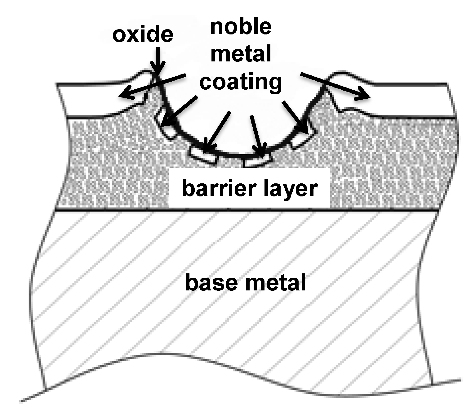
1.2. Fretting Corrosion
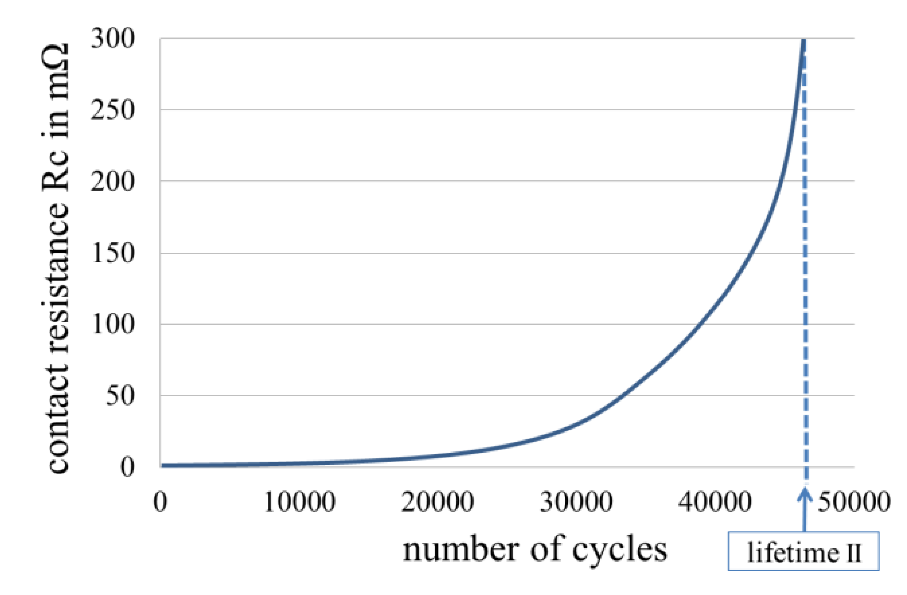
Another phenomenon, which leads to increasing contact resistance, is fretting corrosion. Fretting corrosion is the degradation mechanism of surface material. Fretting corrosion occurs when there is a relative movement between electrical contacts with surfaces of ignoble metal. The small wear particles oxidize and areas of oxides become larger and thicker on the contact surface, Figure 1. The phenomenon of fretting corrosion is also a familiar factor in connection with mechanical bearings. However, the effects of fretting on electrical contacts are different from the effects on bearings. Since the basic function of electrical contacts is electrical conduction and oxides are electrically resistant, with a small amount of oxides being already sufficient to lead to failures of electrical contacts, fretting corrosion, depending on displacement amplitude and frequency, can become significant shortly after it has commenced. The high specific electrical resistance of oxides leads to a rapid increase of electrical contact resistance, which results in intermittency or failure of electrical connection. The number of cycles of motions to the rapid increase of contact resistance is defined as lifetime in the fretting corrosion tests, since it has the strongest impact on the behavior of electrical contacts, Figure 1.
Figure 1.
Lifetime in fretting corrosion tests.
Both external forces e.g. those due to vibrations or local differences in thermal expansion can cause the relative movement between the electrical contacts. Electrical contacts must often be used in places with vibration. The thermal expansion on each of the two sides of electrical contacts often varies. A typical example is the combination with a thermoplastic housing on the one side and a printed circuit board (PCB) of a highly glass fiber reinforced thermoset resin with a large proportion of fibers on the other side of an electrical contact. Avoiding fretting corrosion is therefore extremely challenging in electronic devices with pluggable electrical connections.
1.3. Development of Fretting Corrosion
Fretting corrosion is mainly fretting oxidation of the zone of contact of electrical contacts. The causes of fretting corrosion are wear debris and oxides, which form a thick insulting layer in the zone of contact of the mating surfaces. It is presumed that fretting is concerned with slip amplitudes not greater than 125 μm. Since this movement is of limited amplitude, it is ineffective in flushing away the wear debris and accumulating oxides in the zone of contact of the mating surfaces [5]. Oxides should be regarded as the main cause for the rapid increase of contact resistance because of their high specific electrical resistance.
Depending on the material used for the plating of electrical contacts, the fretting process can be a one-stage process for ignoble metals such as tin and nickel or a two-stage process for noble metals such as gold, palladium and silver. If ignoble metals are exclusively used as plating material, it is a one-stage process. In this case, the fretting corrosion normally occurs after a small number of slow relative movements. The wear of ignoble metal platings is therefore not decisive for fretting corrosion. If a noble metal, such as gold, is used as the final coating material, the fretting corrosion can only occur after the wear-through of the final coating. The first stage is the fretting wear of the final coating and the second stage is the fretting corrosion of the interlayer. Therefore, fretting wear should also be studied in order to deal with the topic comprehensively.
1.4. Fretting Wear
Relative motions between electrical contacts lead to wear of the coatings. The causes of coating wear can be a result of different thermal expansions on both sides of electrical contacts, mating of contacts or mechanical vibration. Therefore, the wear resistance of coatings should also be investigated. The topic of the wear resistance is especially important for gold plating, since gold plating is normally very thin due to cost factors and pure gold is very soft. It is well known, from the study of tribology, that in general hard materials are more wear resistant than soft materials, provided other characteristics of the materials are the same [6]. In order to increase the wear resistance, hard gold, which is an alloy of gold and cobalt, gold and iron or gold and nickel, are used as plating materials for electrically conductive surfaces. The higher hardness decreases the wear of the final coating and delays the onset of the fretting corrosion. A hard gold plating of 0.8 micron can survive 100 to 500 mating cycles without wear-through [7,8]. If a higher number of mating cycles is required, a gold plating thickness of up to 3 to 5 microns may be used.
Fretting corrosion and fretting wear are two different phenomena. Based on the wear mechanisms, fretting wear can be adhesive wear or/and abrasive wear. A differentiated investigation of the two phenomena is important so as to understand the fretting process. This is especially true for electrical contacts with a plating of noble metal. Since noble metals do not oxide, fretting wear alone would not impair the electrical conduction. For plating with noble metals, the development of fretting corrosion can be largely influenced by the wear of the final coating. The correlation between electrical and tribological properties has therefore been studied by many authors [6,9,10,11].
1.5. Wear Patterns of Electrical Contacts
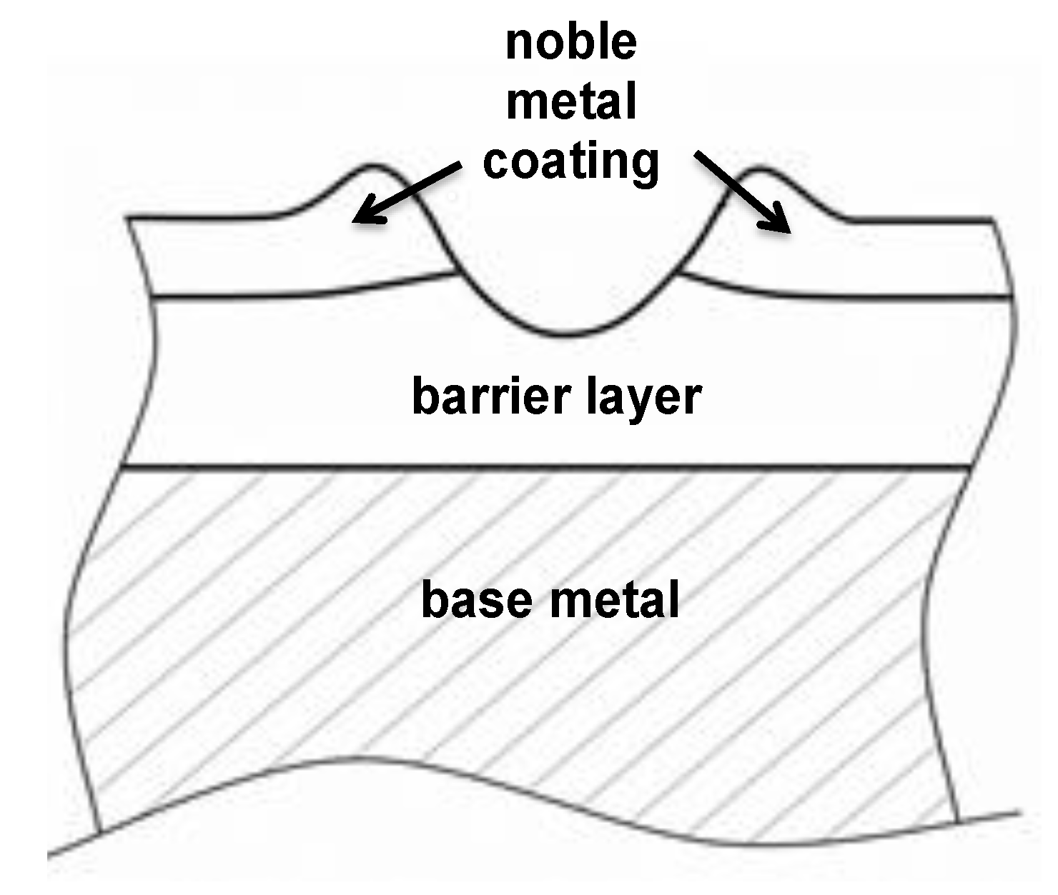
In the case of a wear-through of the final coating, electrical contacts do not necessarily fail. There are different wear patterns of wear-through. Starting with the plating systems shown in Figure 2 three wear patterns can possibly develop [11].
The first wear pattern is the total wearing out of the final coating, Figure 3. The abrasive wear is the dominating wear mechanism in this case. There is the direct contact of the interlayers (barrier layers) which is sensitive to fretting corrosion. Therefore the electrical contacts fail shortly after this stage has been reached.
Figure 2.
Cross-section of plating system of electrical contacts before the wear and fretting corrosion test.
Figure 2.
Cross-section of plating system of electrical contacts before the wear and fretting corrosion test.

Figure 3.
Wear pattern I—total wear out of the final coating. Cross-section of plating system of electrical contacts after the wear and fretting corrosion test.
Figure 3.
Wear pattern I—total wear out of the final coating. Cross-section of plating system of electrical contacts after the wear and fretting corrosion test.

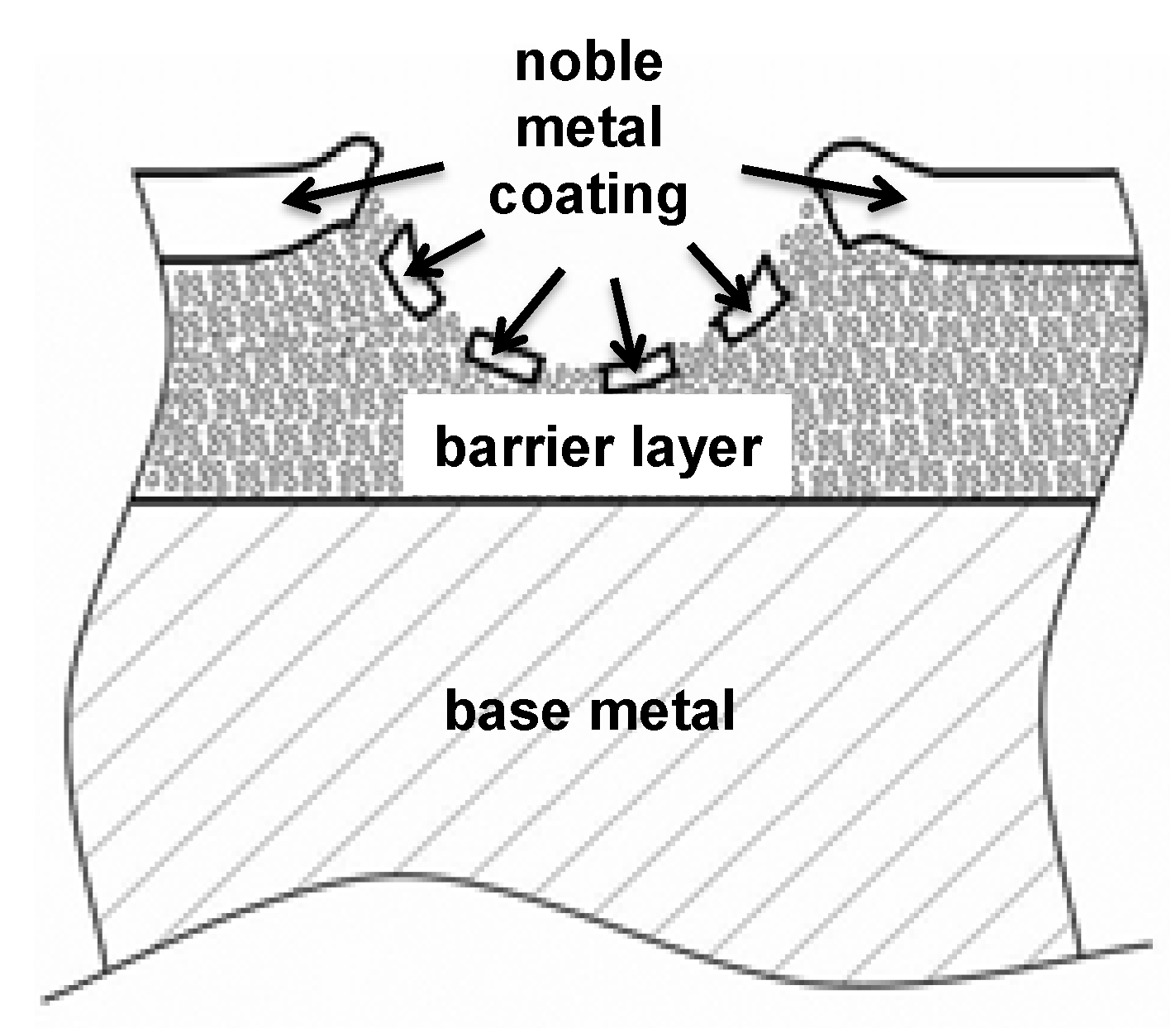
The second wear pattern is the most prevailing one for electrical contacts. Noble metal pieces are found in the zone of contact and they are not covered with oxide, Figure 4. Therefore a low contact resistance is measured in this case. The electrical contacts work properly.
Figure 4.
Wear pattern II—partial wear out of the final coating and contact surface not totally covered with oxide.
Figure 4.
Wear pattern II—partial wear out of the final coating and contact surface not totally covered with oxide.

Adequate contact normal force is necessary for a stable electrical contact. Combined with a soft contact surface, a small displacement in amplitude and where applicable a liquid lubricant, the contact force often makes the zone of contact gas-tight. Therefore, if the electrical contacts are not unmated, corrosive media or gases cannot gain access to the zone of contact with a defective final coating. Electrical contacts can survive for a substantial amount of time even in an environment with corrosive gases.
However, noble metal at the bottom of the wear crater is not the only criterion for the proper functioning of electrical contacts. If the noble metal pieces are covered with debris of oxide, Figure 5, the contacts will also fail. In cases of both wear pattern II and wear pattern III, the adhesive wear plays an important role.
Figure 5.
Wear pattern III—partial wear out of the final coating and contact surface totally covered with oxide.
Figure 5.
Wear pattern III—partial wear out of the final coating and contact surface totally covered with oxide.
1.6. The Main Scope—Solutions for Combined Protection against Corrosion, Fretting Wear and Fretting Corrosion
The above description shows that a very high corrosion resistance of coatings is a necessary condition for good protection of electrically conductive surfaces. However this alone is not sufficient for good protection. As a result of the motion between electrical contacts, the coatings must also possess a high wear resistance, a high fretting corrosion resistance and of course a high and stable electrical conductivity. Ignoble coating materials such as tin and nickel are all affected by the fretting corrosion. Palladium is normally not subject to corrosion problems. Palladium nickel alloys are mostly used for electrically conductive surfaces. They have an excellent wear resistance, although the high level of brittleness can possibly lead to cracks, which in turn reduces the corrosion resistance. Fretting corrosion is also possible with coatings of palladium [3]. Silver has very high corrosion resistance and is not subject to problems concerning fretting corrosion. Silver is soft and has a low wear resistance. A silver plating of 3 microns is therefore required for more than 50 mating cycles [7]. The most substantial problem with silver is tarnishing in a sulfur sulfite environment. The tarnish film is very soft and can therefore be easily broken by the contact force. It does not show relevant influences on electrical conductivity. However, the visible brown color of the tarnish film suggests changes on surface, which are often regarded as failures. Gold alloys fundamentally have the combination of desired properties for the overall protection of electrically conductive surfaces. The critical points with gold coating are the wear resistance and the materials cost. We have discovered some measures to increase the wear resistance of gold coatings and to reduce the materials consumption of gold.
There are a variety of basic approaches to the solutions of the problems caused by fretting wear and fretting corrosion. Noble metals as final coating materials, design which reduces the wipe caused by external forces and thermal expansion, lubricants that prevent the zone of contact from exposure to the atmosphere and therefore from the fretting oxidation, are widely used measures to enhance the resistance to fretting corrosion. If using noble metals, the wear resistance of the plating, material and cost saving should be especially considered. Problems with lubricants could be the long-term stability factor and the high operating temperature. Most lubricants evaporate extremely fast at temperatures of over 100 °C.
Gold is the plating material with the best corrosion resistance and therefore one of the most commonly used noble plating materials for high performance electrical contacts with good and stable electrical behaviors. Today well over 300 t of gold are used annually in electronic components and a large proportion of this amount is used as plating material for high performance electrical contacts. Although miniaturization and cost saving efforts, such as selective gold plating, drive down the specific gold input, the booming growth in sales of electronic devices and their new features have led to a constant gold demand in this field in recent years [12,13,14]. In addition to the material cost, the production of gold also causes environmental problems [15]. Therefore, the reduction in the demand for gold on electrically conductive surfaces is of vital importance, from both the economic and ecological point of view. These facts are the reasons that gold alloys and other modifications of gold are the main scope of our investigation.
The basic function of gold platings in electrical contacts is the protection against corrosion and fretting corrosion. The amount of gold used for electrically conductive surface is determined by the area and the thickness of gold plating. The basic idea of selective gold plating is that gold is plated at and around the electrical contact areas and not on the whole surface of electronic components. In this way the area of gold plating can be reduced to the minimum. Depending on the contact operating conditions and contact functions the thickness of gold platings varies from 0.1 to 5 μm. Thick platings are normally used for contacts for high mating cycles or other heavy duty applications. Platings of more than 5 μm are also used. However they do not improve the surface perfections and wear resistance because of stress crack corrosion and therefore should not be used [7,16]. For corrosion protection, gold platings must be free of imperfections (porosity). This feature can be only guaranteed up to a certain degree by a hard gold plating thickness of more than 0.6 μm [17].
Different ways to minimize the consumption of gold for electrically conductive surface and to improve the performance of gold plating were investigated:
- Increasing the hardness by means of:
- Optimized proportion of alloy elements and;
- Hard nanoparticles;
- Improved wear resistance and wear pattern of coatings;
- Improved surface perfection with thin coatings by employing SAM (self assembled monolayer).
The high degree of hardness of hard gold is achieved by alloying elements such as cobalt, iron or nickel. However, the effect of alloying elements is limited by the electroplating process and other surface properties, such as ductility and cracking, which are also important for the final coatings.
Instead of alloying elements, nanoscale particles mostly metal oxides can be used for the modification of gold platings. The reason for using nanoscale particles is based on the fact that the hardness of pure gold is about 70 HV and the hardness of hard gold is about 170 HV (10 N/mm2) [18]. The hardness of nanoscale particles of metal oxides ranges from 700 to 2300 HV (10 N/mm2) [19]. PTFE reduces the friction between contacts. These can provide an additional lifetime improvement [20]. However PTFE is basically an isolator therefore only nanoparticles of PTFE can be used for electrical contacts, in order to alleviate increase of contact resistance.
Another means of corrosion protection of electrically conductive surfaces is the passivation of surface. Passivation is the change process of metal surface, which creates the resistance to environmental media. Metal surfaces can be passivated either by their own gastight oxide layer or through the assembly of a non-reactive layer such as self-organization of nanoparticles, monolayers, SAM (self assembled monolayer). Besides the resistance to corrosion there are two very important requirements for electrically conductive surfaces:
- The passivation layer should not increase or destabilize the electrical resistance markedly and;
- For many applications the passivation layer must resist the operating temperature which is the sum of resistive heating and ambient temperature.
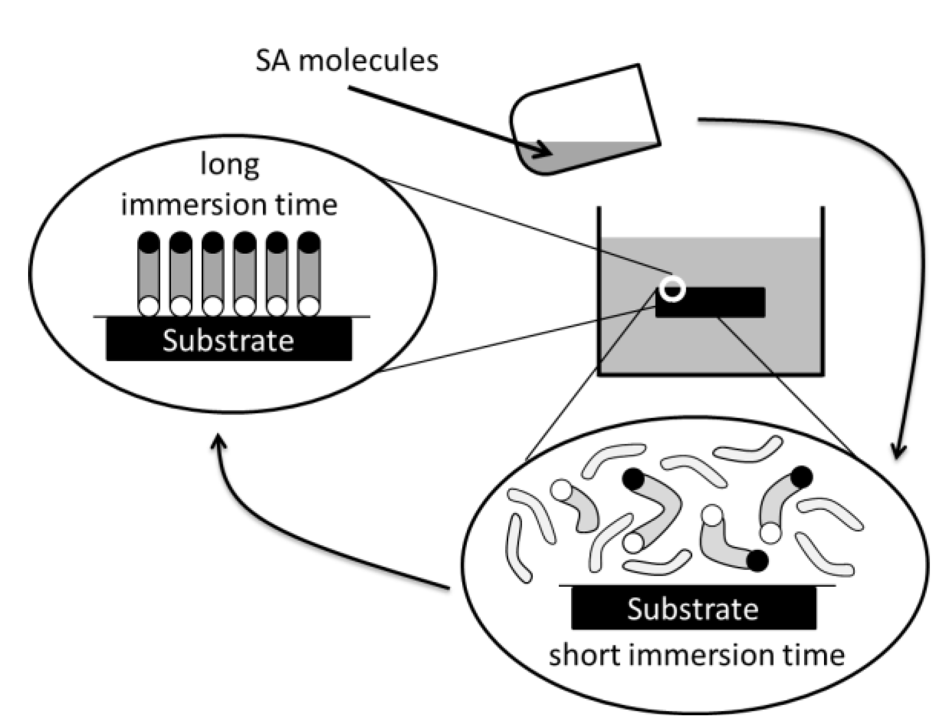
Self assembled molecules are bi-functional or multi-functional molecules that offer two- or more-termination groups with different functionality, Figure 6. Typically one end is attached to a specific surface while the other end provides a specific functionality. These molecules can be attached to metals, Figure 7. In this manner it is possible to impart or enhance the intended performance of a surface or enable completely new applications. The important intended properties for electrically conductive surfaces are high resistance to oxidation and corrosion by lowering porosity, high resistance to wear-through and good electrical conductivity. Self assembled molecules can be applied in different ways, ultrasonic assisted immersion, photo catalytic, electrochemical or gas phase evaporation. Ultrasonic assisted immersion was used for our investigation. In this case, electroplated samples are immersed in the SAM liquid for about one minute and then washed with clear water and dried, Figure 8 [21]. AUTRONEX™ Nano 104S was used for the investigation.
Figure 6.
Molecules for self assembly.
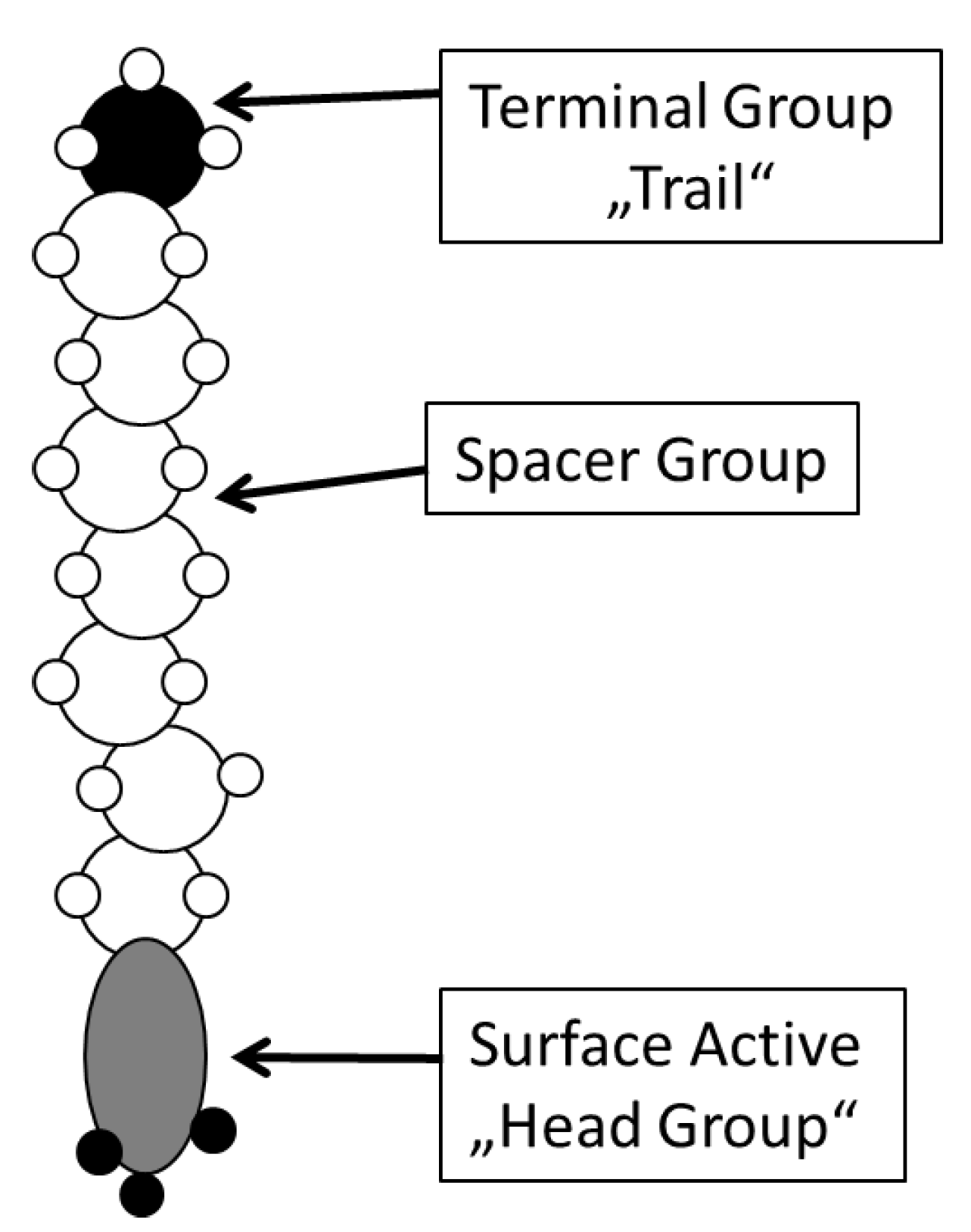
Figure 7.
Method of application—Ultrasonic assisted immersion.

Figure 8.
Methods of Application.
2. Experimental Section
2.1. Corrosion Tests
The resistance to corrosion can be tested by the four gas pollution test (mixed flowing gas test), which simulates an industrial environment [8,22,23]. The four gases, SO2, H2S, NO2 and Cl2, used for the test are typically the main causes for corrosion in an industrial environment. However the test requires sophisticated equipment and takes 10 to 21 days. Special testing methods using one corrosive medium are also used to check corrosion resistance of coatings, SO2 in the Kesternich tests [24,25,26] or salt fog in the salt spray tests [27].
The porosity in gold plating on metal substrates can be also quickly tested by nitric vapor [28]. The part under investigation is exposed to the nitric vapor atmosphere that is corrosive to the base metal. Where there are pores, the reagent attacks the basis metal and generates corrosion products, which result in color change at the spots and make the pores visible. The test is simple and inexpensive and first and foremost quick, with meaningful results being achieved after a period of just 24 hours [29].
2.2. Measurement of Fretting Corrosion and Wear and Surface Analysis
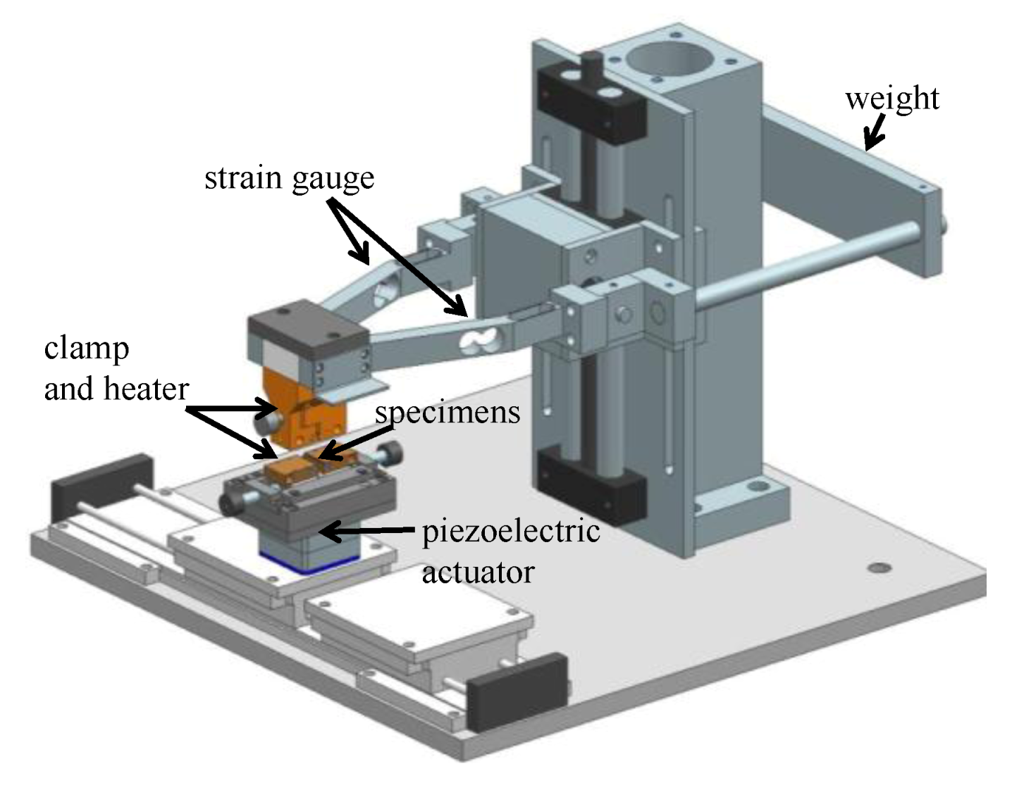
Various test rigs for the measurement of fretting corrosion were introduced [6,9,10,11]. A new piece of equipment with some special features was developed for our investigation. This new equipment enables an in-situ wear measurement with a vertical displacement sensor, a measurement at a high temperature and a continuous monitoring of the normal force and the friction force. A piezoelectrical actuator moving forwards and backwards generates the relative motion between the contacts. The contact force is provided with a dead load. Different normal forces were applied for the investigation. A closed loop heating system enables tests at high temperatures of up to 100 °C. The contacts are wired for a four-wire resistance measurement. A computer controls the data acquisition system.
The actuator of the test rig can be stopped as soon as a certain limit of contact resistance has been reached. This feature is extremely useful for various kinds of investigations, for instance, for the analysis of the state of the contact surface at the moment of an electrical failure [30], Figure 9.
Figure 9.
Apparatus for wear and fretting corrosion tests.

The parameters of testing are wipe, contact normal force, frequency of the motion and temperature. The wipe can be varied between 1 to 200 μm, the contact normal force from 0.5 to 5 N and the frequency from 0.1 to 10 Hz. Unless otherwise indicated, the measurements were mainly conducted at 50 μm wipe, 2 N contact normal force and 1 Hz. This frequency has been proven to be suitable for the lifetime forecast of the fretting corrosion induced by local differences in thermal expansion. A higher frequency would lead to an unrealistic higher lifetime value in tests due to the too short exposure time of the contact surfaces within each cycle. The choice of parameters is based on a study that optimized the reproducibility of the measurements and the test duration [30]. The environmental conditions are ca. 20 °C and 50% RH.
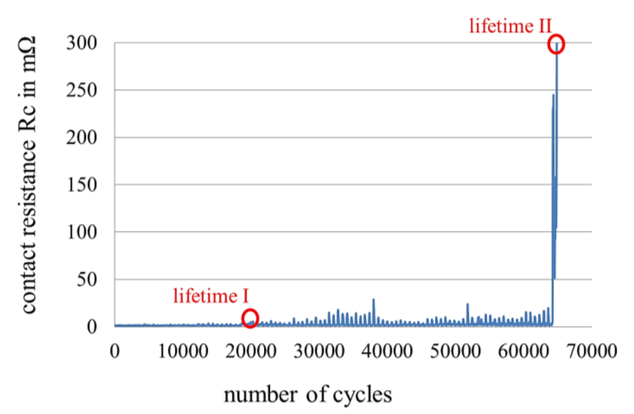
Several criteria can be used to determine the lifetime of electrical contacts. The number of cycles to the rapid increase of contact resistance is normally used in fretting corrosion tests as lifetime, since it has the strongest impact on the behavior of electrical contacts. Two limits are set for the lifetime. Lifetime I is defined as the number of cycles which leads a 300% increase of contact resistance and lifetime II as the number of cycles when the contact resistance of 300 mΩ is measured [31]. Lifetime II is a system-oriented definition, which is applicable for small electrical contacts with an initial contact resistance of about 1 to several mΩ and electronic systems which allow a such contact resistance. At the end of lifetime I initial damages on final coatings occur and the contacts can normally still work properly. At the end of lifetime II a normal function of electrical contacts cannot be expected, Figure 10.
Figure 10.
Increases in contact resistance due to fretting corrosion [31].
Figure 10.
Increases in contact resistance due to fretting corrosion [31].

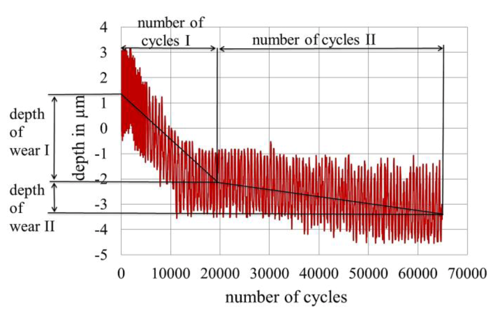
The wear of electrical contacts was measured simultaneously to the contact resistance during the tests. The rate of wear, which is defined as depth of wear per 1000 cycles of motion, can be calculated from the wear curve. There are typically two phases of wear. The first phase is the wear of the final coating, which normally takes place faster than the second phase. The second phase is the wear of the interlayer or the base metal, Figure 11. There is usually a very good correlation between phase I of wear and lifetime I of electrical contacts, since the instant of time of phase I of wear corresponds to the instant of time of a partially worn through of the final coating which leads to first instabilities of electrical contacts. The rate of wear in phase I of wear represents the wear performance of the final coatings. The rate of wear is therefore relevant for the study of final coatings.
Figure 11.
Wear rate I and II.

A transmission electron microscope (TEM) combined with an image processing program was used for characterization of nanoscale particles powder. An Ultrafine Particle Analyzer (UPA), which incorporated the Controlled Reference Method (CRM) in a dynamic light scattering instrument, was used to determine the particle size distribution in electrolytes. The wear of the zone of contact was measured after the wear test with a confocal laser scanning microscope (CLSM), which measured the surface topography with a precision of up to 10 nm. A scanning electron microscope (SEM) with a Focused Ion Beam System (FIB) and an energy-dispersive X-ray spectroscopy (EDX), an X-Ray fluorescence spectrometer and an optical microscope were also used for the material and surface analysis of the gold plating.
2.3. Sample Size, Base Materials and Plating Materials
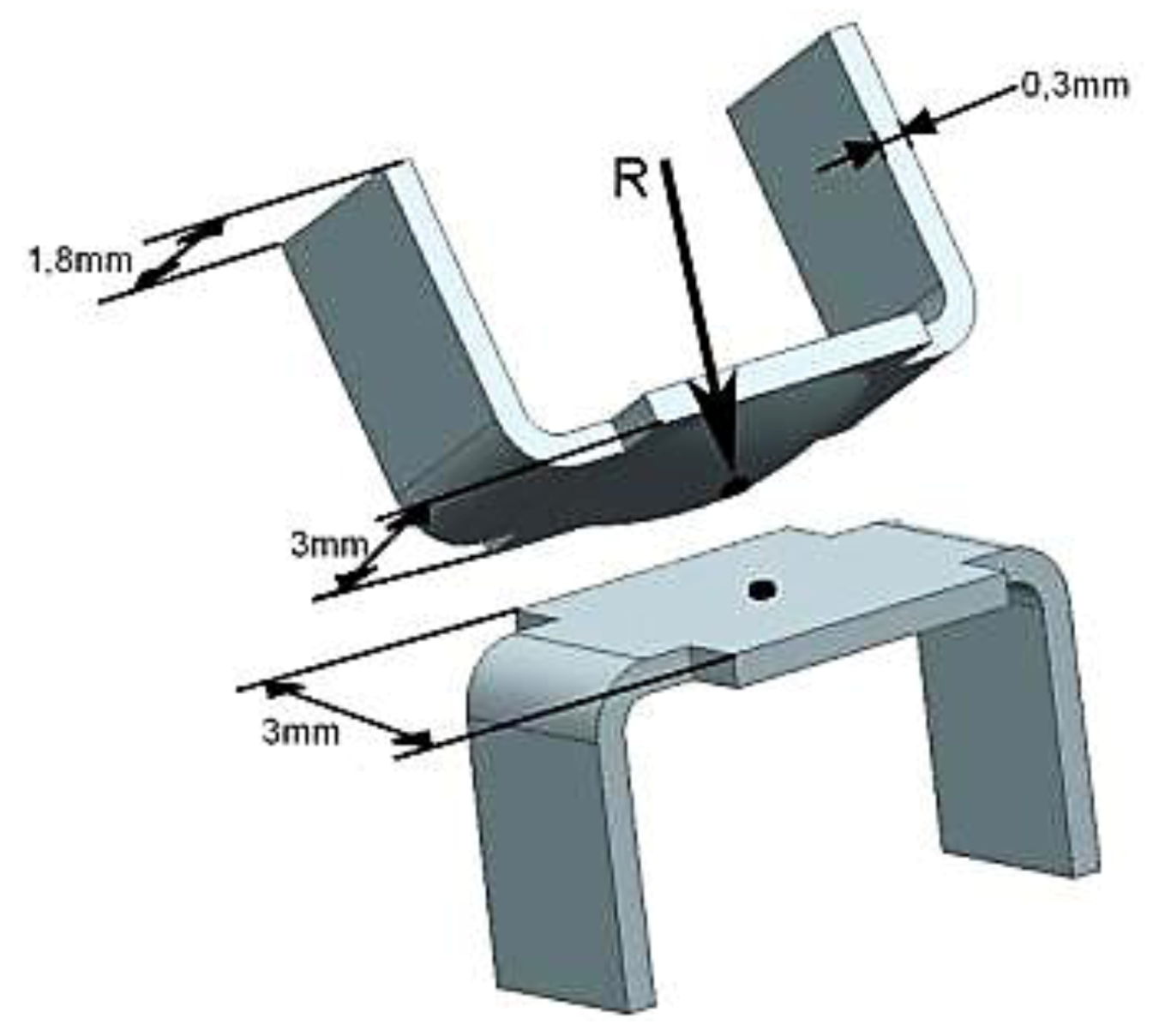
The contact springs were stamped. The size and set-up are shown in Figure 12 and Figure 13. The base metal used was bronze (CuSn).
Figure 12.
Sample size A, radius of contact cylinder R = 2.0 mm.

Figure 13.
Sample size B, radius of the contact sphere R = 1.5–4.5 mm.

The coating systems tested in this study were platings of tin, silver and gold. Both pure gold and various kinds of modified hard gold were used as plating materials. The modification was conducted by alloying elements cobalt, iron or different nanoscale particles. The nanoscale particles used for the investigation were of aluminium oxide, titanium dioxide, titanium nitride, silicon carbide (carborundum), silicon oxide, silicon nitride, nanodiamands, zirconium dioxide (zirconia) and B4C3. For gold plating as final coating, there was always an interlayer (barrier layer) of nickel, which prevents the diffusion between gold and base material. The samples were all electroplated. The thickness of gold was between 0.6 and 1 µm. The mating parts for each test were always coated with the same coating system.
3. Results and Discussion
3.1. Porosity and Corrosion Resistance
3.1.1. Thickness and Porosity of Gold Coating
In order to reduce the mating force, the materials consumption and the processing time the thinnest possible thickness of coatings should be used. This is especially true for noble metals such as gold. However the coating must fulfill its basic function of corrosion protection and therefore must be technically free of pores. If there are pores in the coating, active metals under the coating react with corrosive media and produce corrosion products which significantly increase the contact resistance and break the electrical contacts. It means that the porosity must be reduced to the degree that no failures on the coating can be observed after the required corrosion test. These are contradictory requirements for the thickness of coatings. That means the thickness of coatings should be optimized with regard to the corrosion resistance, the mating force, the materials consumption, the processing time and the wear resistance, which will be discussed at a later stage.
The porosity of gold coatings with different thickness was tested at the first step. Samples with a thickness of 0.2 to 1.0 µm were put in an exsiccator containing nitric acid of 65%. The exsiccator was heated to 60 °C for 75 min. The samples were dried at 80 °C for 45 min. after the exposure. Corrosion spots could be observed under a microscope with a magnification factor of 25. Many corrosion spots could be observed on the coatings with a thickness of 0.2 µm to 0.5 µm. Only a very small number of corrosion spots were observed on the coating with a thickness of 0.6 µm and no corrosion spots were detected on the coatings with a thickness of 0.8 µm and 1.0 µm (Figure 14). These results confirmed the assumption that the porosity of coatings decreases with increasing thickness. The fact that no corrosion spots were observed at the thickness of 0.8 µm and more is also the reason for the thickness of 0.8 µm, which is very often specified for gold coatings.
Figure 14.
Gold coating with a thickness of 0.2–1.0 µm after exposure to nitric vapor for 75 min. at 60 °C.
Figure 14.
Gold coating with a thickness of 0.2–1.0 µm after exposure to nitric vapor for 75 min. at 60 °C.

3.1.2. SAM and Porosity
As mentioned above self assembled molecules can be used on electrically conductive surface to increase the resistance to oxidation and corrosion by lowering porosity. The effects of SAMs were tested with samples with a gold coating of 0.4 µm.
The large difference on the surface after a corrosion test (exsiccator with nitric acid of 65%, 60 °C for 75 min, dried at 80 °C for 45 min. after the exposure) is shown in Figure 15. Pores can be observed in both cases because of the thin gold platings. Yet no corrosion spots can be sighted on the sample treated with SAMs.
Figure 15.
(a) Comparison of contact surface with; and (b) without SAMs (AUTRONEX™ Nano 104S) after corrosion test, thickness of gold coatings 0.4 μm, sample size B.
Figure 15.
(a) Comparison of contact surface with; and (b) without SAMs (AUTRONEX™ Nano 104S) after corrosion test, thickness of gold coatings 0.4 μm, sample size B.
3.2. Corrosion Resistance of Other Coating Materials
The corrosion resistance of different coating materials in the Kesternich test (DIN 50018 and DIN EN ISO 3231) is shown in Table 2. The measure of the corrosion resistance is the change of contact resistance after the test. A large change means a low corrosion resistance. The volume of the test chamber was 300 L. The corrosive medium used was SO2. In the first cycle 0.1 L of SO2 was applied and in the second cycle 1 L. The corrosive load of the second cycle is therefore much higher than that of the first cycle. The duration of each cycle is 24 h, 8 h at 40 °C and 16 h at 23 °C. The thickness of the coatings is within the range of typical technical applications.
Table 2.
Corrosion resistance and change of contact resistance of different coating materials, contacts separated during the test procedure.
| Coating material | Thickness in micron | Contact resistance in milliohm | Change of contact resistance | |
|---|---|---|---|---|
| initial | After 1st cycle | After 2nd cycle | ||
| Ni | 4.3 | 73.08 | 8200% | 40000000% |
| Sn dull | 4.3 | 2.91 | 70%–180% | 350% |
| Sn bright | 6 | 2.29 | 14% | 5450% |
| Ag | 6.1 | 2.64 | 50% | 335% |
| Pure Au | 0.4 | 14.33 | −50% | 60%–225% |
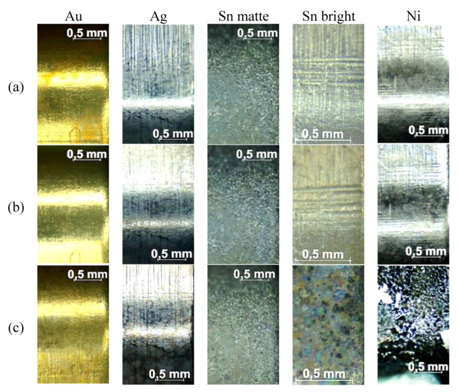
Among these most common used coating materials for electrically conductive surfaces gold has the highest corrosion resistance. This can also be observed microscopically. While no trace of corrosion could be found microscopically on the surface of gold coating, clear marked corrosion areas could be found on the surfaces of nickel, tin and silver coatings after the cycle of corrosion test. After the second cycle of the corrosion test, which is much more intensive than the first cycle, corrosion areas could be observed on all coatings, Figure 16. The different degree of changes in contact resistance and the different optical appearances also show the difference in corrosion resistance of different coating materials.
Figure 16.
(a) Surfaces of different coating materials before; (b) after the first cycle test; and (c) after the second cycle test of corrosion.
Figure 16.
(a) Surfaces of different coating materials before; (b) after the first cycle test; and (c) after the second cycle test of corrosion.

3.3. Fretting Corrosion
The main difference between noble and ignoble coating materials is not in different functionalities of passive ignoble and noble metals are not in the corrosion resistance but in the resistance to fretting corrosion. Passive ignoble metals such as tin and nickel are used as plating materials for the improvement of corrosion protection and electrical contact. They are however sensitive to fretting corrosion. Noble metals offer both corrosion protection and protection against fretting corrosion. This defines the special feature of noble metals as plating materials, in particular gold, which is widely used for high performance contacts. However the important characteristics of gold, such as its hardness, wear resistance and ductility can vary substantially. This results in a large lifetime difference in wear and fretting tests [2,6,32,33,34].
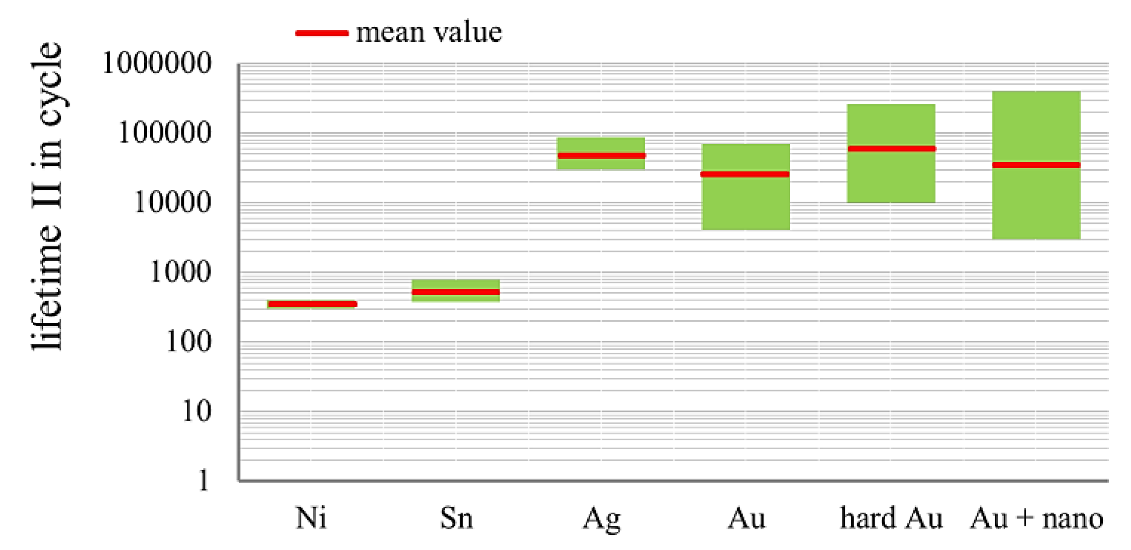
The ranges and mean values lifetime of the electrical contacts with coatings of pure gold, hard gold and nanoparticles enhanced gold in the wear and fretting corrosion tests is compared in Figure 17.
Figure 17.
Comparison of the ranges and the mean values of lifetime of different coating materials in fretting corrosion tests. Au + nano: values with all particles included s. a. 3.3.2.
Figure 17.
Comparison of the ranges and the mean values of lifetime of different coating materials in fretting corrosion tests. Au + nano: values with all particles included s. a. 3.3.2.

The fact that the hard gold and nanoscale particles modified layers show both an extraordinary long and short lifetime reveals that
- There is a large potential in terms of improving the lifetime of gold layers with alloy elements and nanoparticles;
- Putting alloy elements or nanoscale particles alone in the layers would not be sufficient. Other basic conditions have to be taken into account in order to achieve the desired effects.
Therefore, further investigations were conducted to study these basic conditions.
3.3.1. Influence of Proportion of Alloy Element in Gold Coatings on the Lifetime in Fretting Corrosion Tests
The influence of alloy element content in hard gold on the properties of layers has already been observed by other authors. The hardness, for instance, increases with increasing alloy element content [5,6,16]. In our investigation the proportion and the kind of alloying elements are varied systematically. Since the wear resistance is enhanced with increasing hardness, a relevant influence of the alloy element content in hard gold on both lifetime I and II in fretting and wear test can be expected.
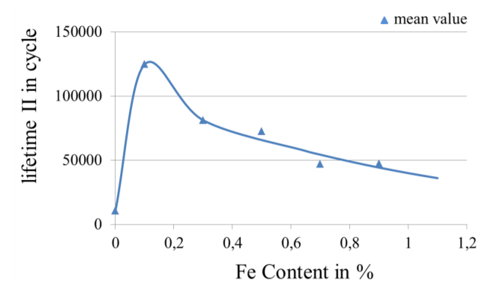
Figure 18.
Effect of Fe content in gold layer on lifetime in fretting and wear test. Number of measurements: 129.
Figure 18.
Effect of Fe content in gold layer on lifetime in fretting and wear test. Number of measurements: 129.

Figure 19.
Effect of Co content in gold layer on lifetime in fretting and wear test. Number of measurements: 72.
Figure 19.
Effect of Co content in gold layer on lifetime in fretting and wear test. Number of measurements: 72.

Figure 18 shows that there is an optimum alloy element content in hard gold. This is also true for cobalt. A further increase in the cobalt content will lead to cracks on the coating and rapidly reduces the lifetime, Figure 19.
The course of the curve is the addition of two effects of alloy elements. The first being the effect of the alloy element, which influences the hardness. As previously mentioned, the wear resistance of the layer increases with increasing hardness. The second effect is the ductility, which influences the wear pattern. With decreasing ductility the tendency to brittle-fracture wear is increased and therefore the tendency to total wear-through. A similar observation was also made by another author [6].
3.3.2. Influence of Nanoscale Particles in Electrolytes on the Lifetime in Fretting Corrosion Tests
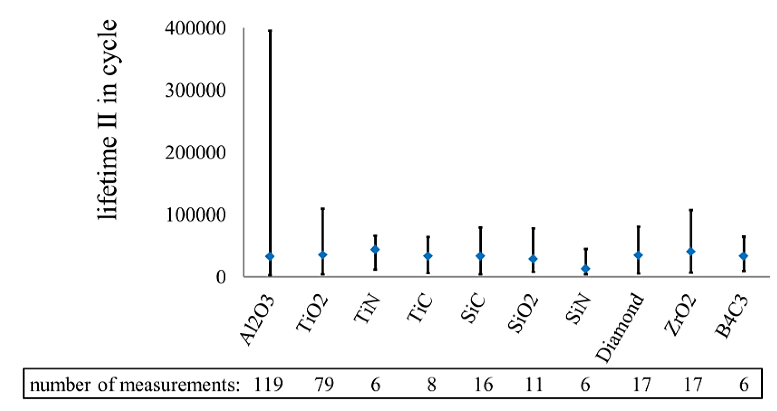
At the beginning of the investigation with nanoscale particles a scanning test was conducted. All the nanoscale particles which would potentially increase the wear resistance markedly were used for the investigation. They were aluminium oxide, titanium dioxide, titanium nitride, silicon carbide (carborundum), silicon oxide, silicon nitride, nanodiamands, zirconium dioxide (zirconia) and B4C3. The best results were achieved with aluminium oxide and titanium dioxide, Figure 20. Therefore only these two materials were used for the further investigation.
Figure 20.
Effect of different nanoparticles on the lifetime of electrically conductive surfaces in fretting corrosion tests.
Figure 20.
Effect of different nanoparticles on the lifetime of electrically conductive surfaces in fretting corrosion tests.

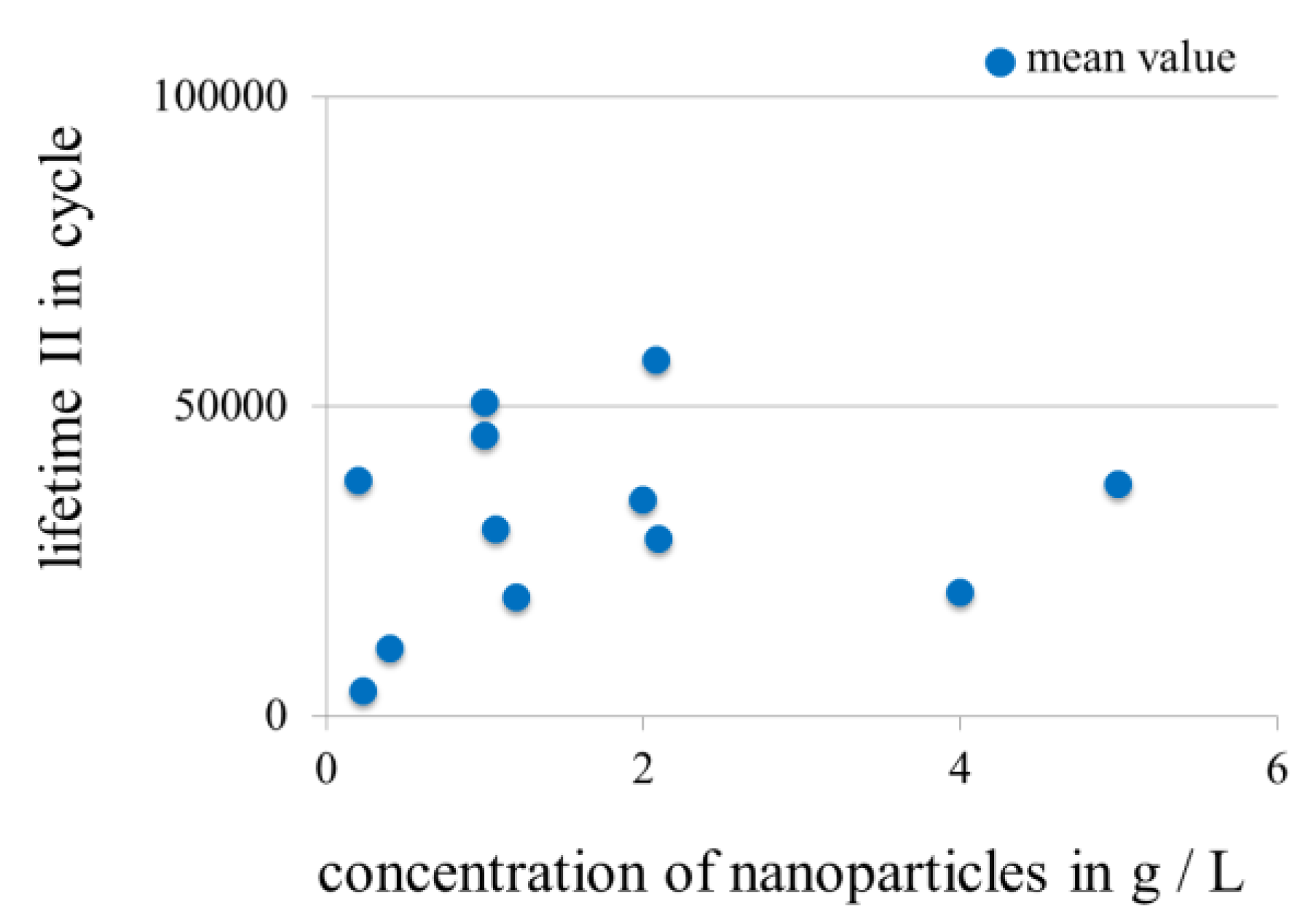
3.3.3. Influence of Concentration of Nanoscale Particles in Electrolytes on the Lifetime in Fretting Corrosion Tests
The samples were plated with electrolytes of different nanoscale particle concentration. The increase of the concentration did not improve the performance of the layers, Figure 21.
Figure 21.
Effect of concentration of nanoscale particles in electrolyte (particles as powder).
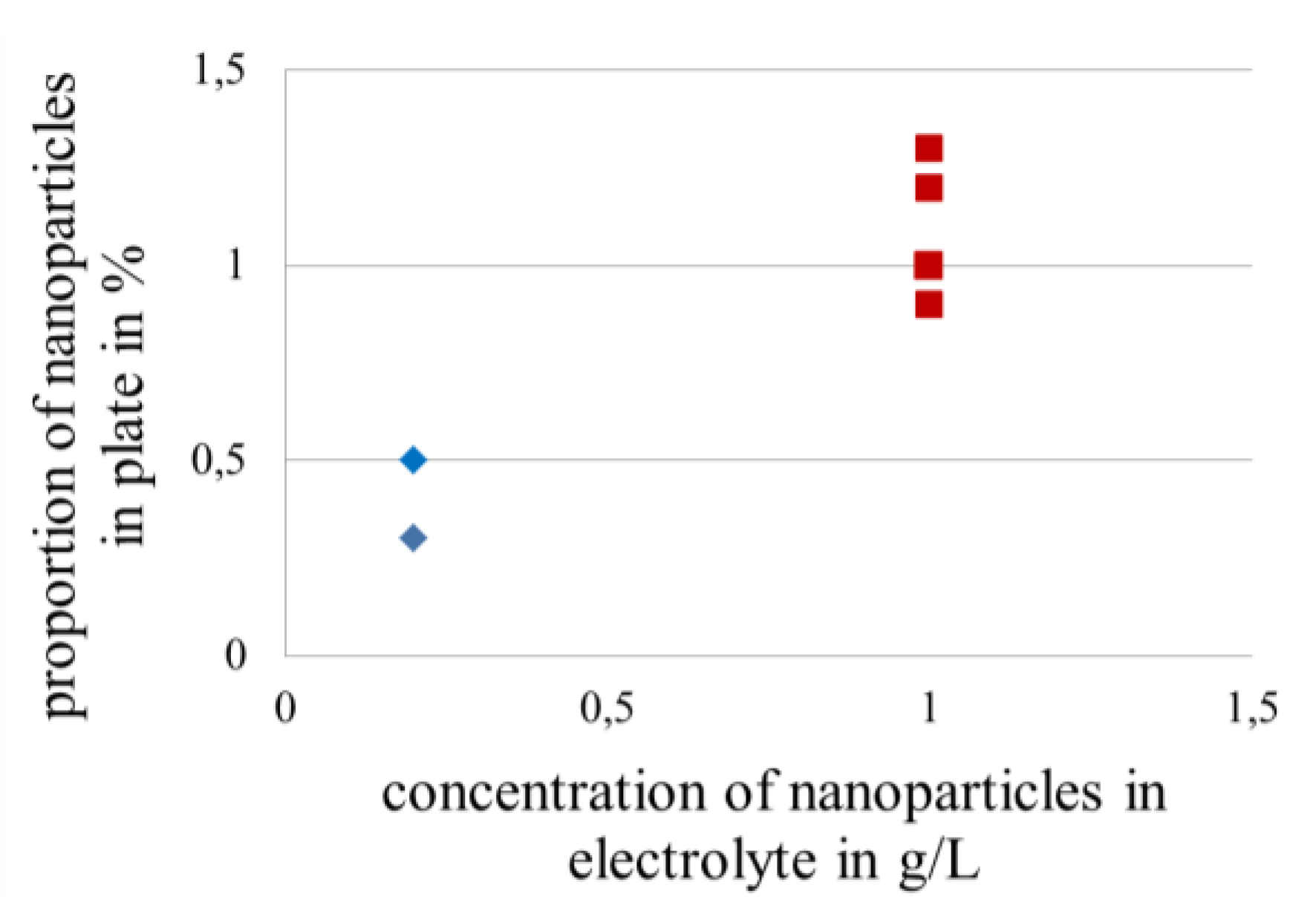
Measurement of the amount of nanoscale particles in gold layers can be carried out using an energy-dispersive X-ray spectroscopy (EDX) or an X-Ray fluorescence spectrometer. Both methods are time consuming, since the samples must be individually measured. A very good correlation between the amount of nanoscale particles in gold layers and the amount of nanoscale particles present in electrolytes was found. Therefore the amount of nanoscale particles in gold layers can be indirectly determined by the concentration of nanoscale particles in electrolytes, Figure 22.
Figure 22.
Correlation between the amount of nanoscale particles in layers and in electrolytes.
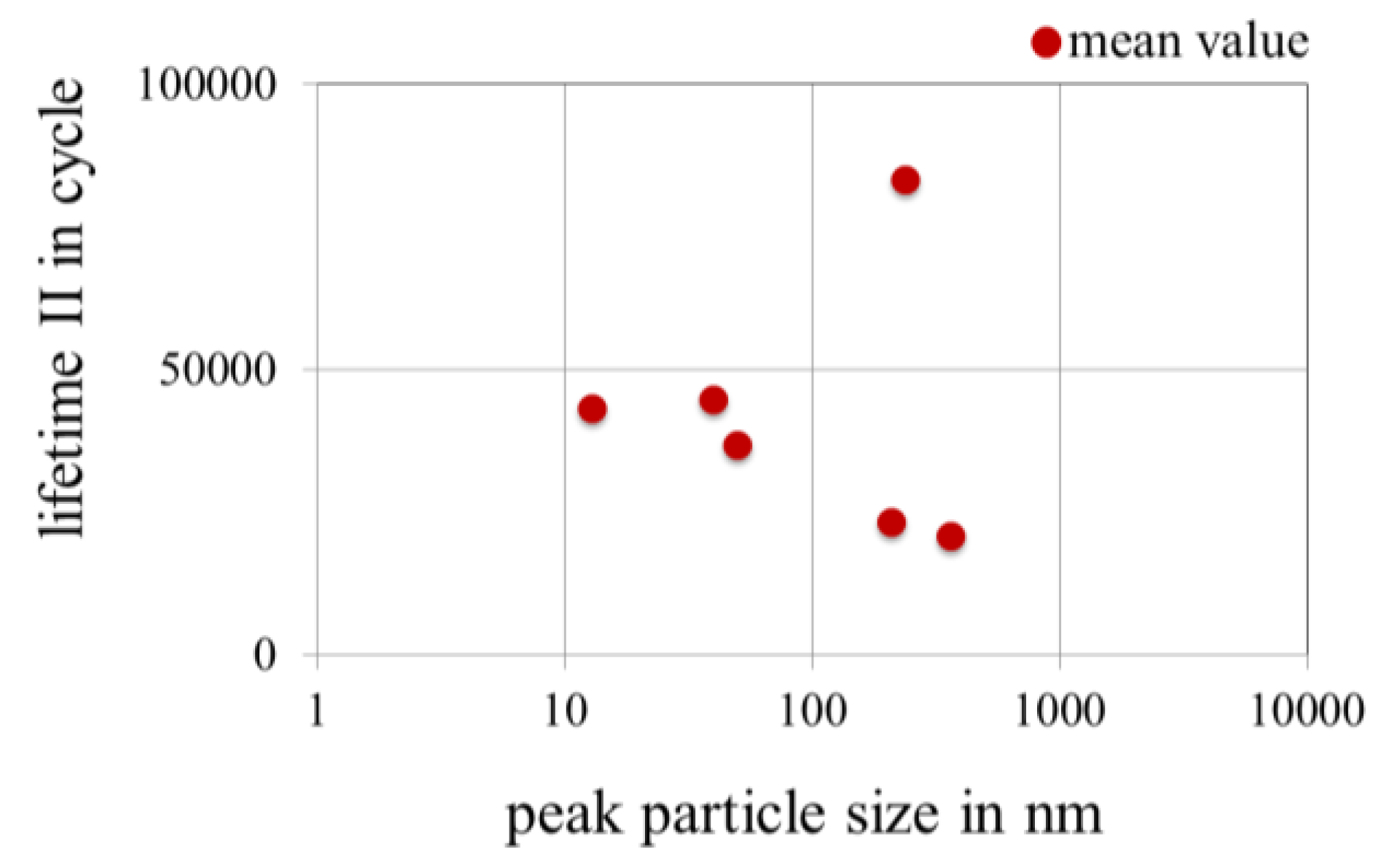
3.3.4. Effect of Peak Particle Size of Nanoparticles in Gold Coatings on the Lifetime in Fretting Corrosion Tests
The peak particle size is defined as the most frequently observed size of nanoparticles. It is therefore one of the characteristics of nanoscale particles. Smaller nanoparticles are in general more difficult to produce than larger ones, but thought to be more strongly bound to the matrix material because of their larger specific surfaces (surface/volume). Figure 23 shows that this does not necessarily lead to a long lifetime.
Figure 23.
Effect of peak particle size in powder. Number of measurements: 86.
Nanoscale particles tend to agglomerate in electrolyte. Due to this, the peak particle size measured in electrolytes is much larger than that in powder or water. Figure 24 shows that if the agglomerates become too large, the average lifetime will be shortened. The limit seems to be the thickness of the gold layer.
Figure 24.
Effect of peak particle size in electrolytes. Number of measurements: 86.

3.3.5. Effect of the Thickness of Gold Coatings on the Lifetime in Fretting Corrosion Tests
Since the wear of layers is proportional to the cycles of motion, the number of cycles to the wear-through of the gold layer should be proportional to the thickness of the gold layer. Once the gold layer is worn out, the fretting corrosion of the interlayer can commence. Therefore a dependence of lifetime on the thickness is expected. Our results showed that a minimum thickness of approximately 0.7 μm is required to achieve a long lifetime. However, thickness is a necessary but not sufficient condition for a long lifetime. Some samples with a thick layer also displayed a short lifetime.
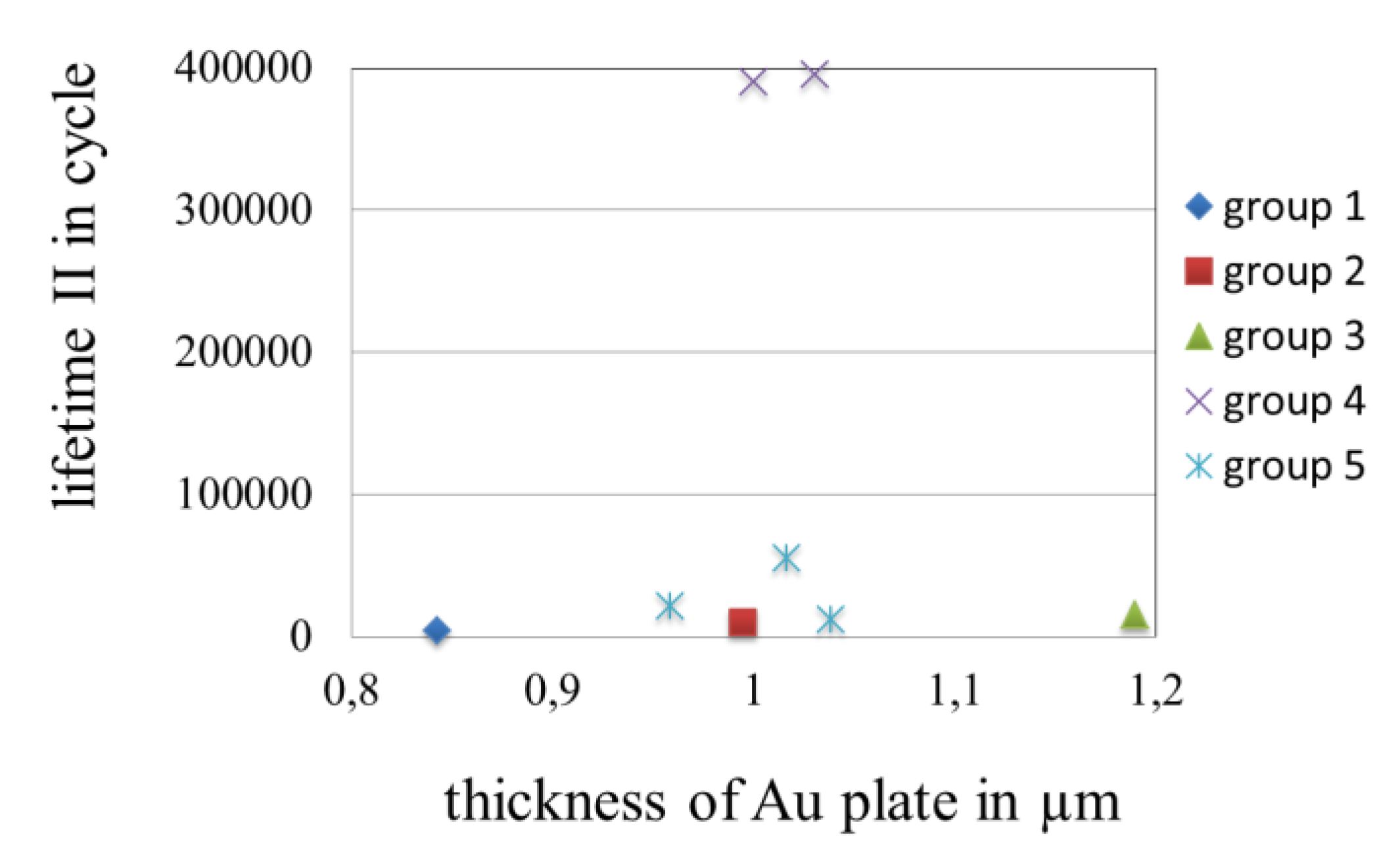
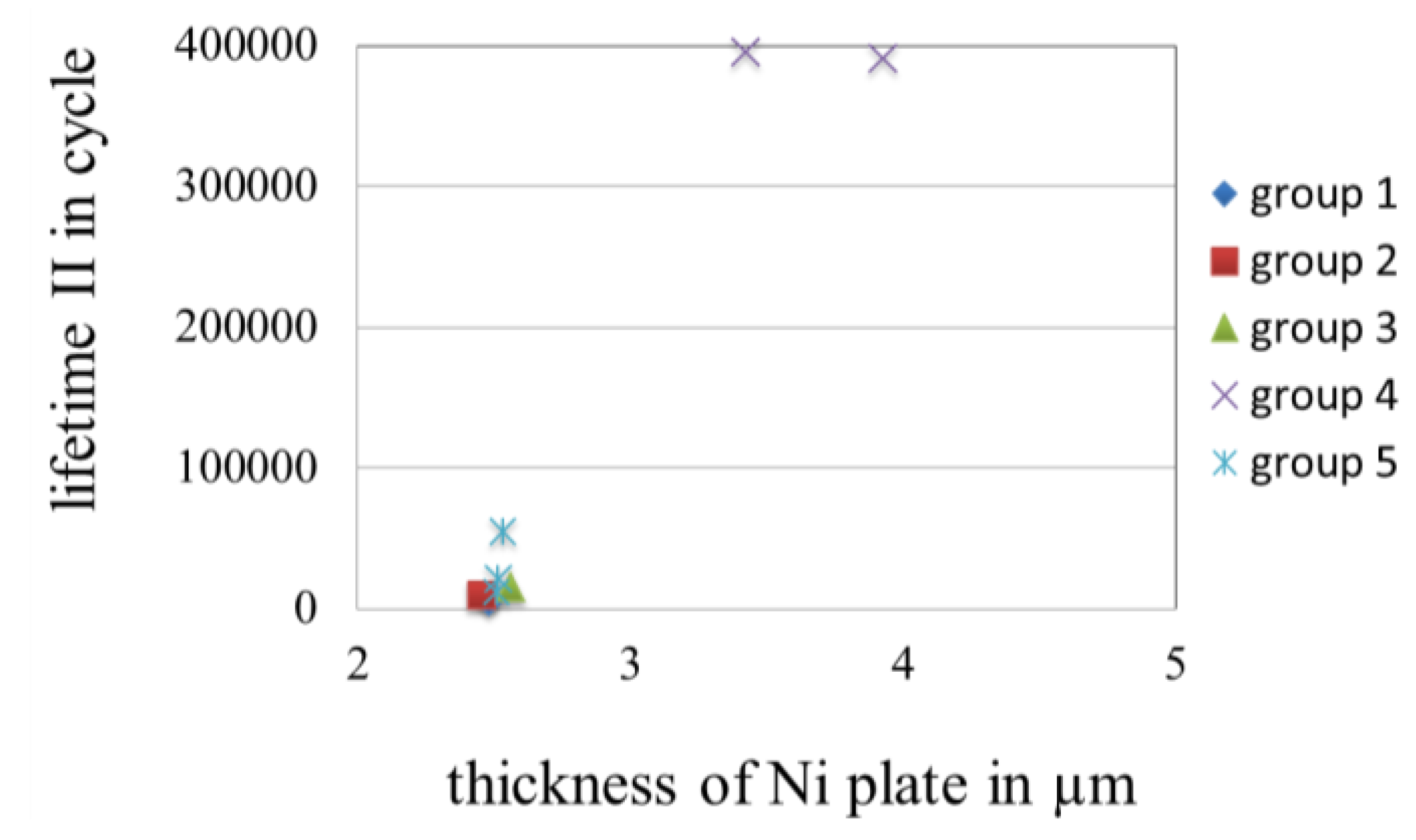
A nickel interlayer has to be applied as the barrier layer to avoid the migration of materials. The properties of the nickel interlayer, such as the thickness and the roughness, also have an impact on fretting corrosion resistance of electrical contacts. An interaction between the final coating and interlayer was also observed [6]. In the wear and fretting corrosion test, nickel interlayers showed a strong effect on the lifetime of electrical contacts. The detailed analysis of a batch of nanoscale particles, which showed the longest average lifetime II of about 120,000 cycles, confirmed the importance of nickel interlayers. At first glance there is also a very large scattering of results. The thickness of the batch ranged from 0.85 to 1.2 μm. However the best samples had a thickness of 1 μm, Figure 25. Nevertheless the determining importance of nickel interlayers could be clearly revealed, see Figure 26. Samples with nickel interlayers of 2.3 μm or less survived less than 10,000 cycles. All samples which survived an exceptionally large number of cycles of more than 200,000 have a nickel interlayer of more than 3 μm.
Figure 25.
The lifetime and the thickness of gold platings.

Figure 26.
Effect of thickness of nickel interlayers.

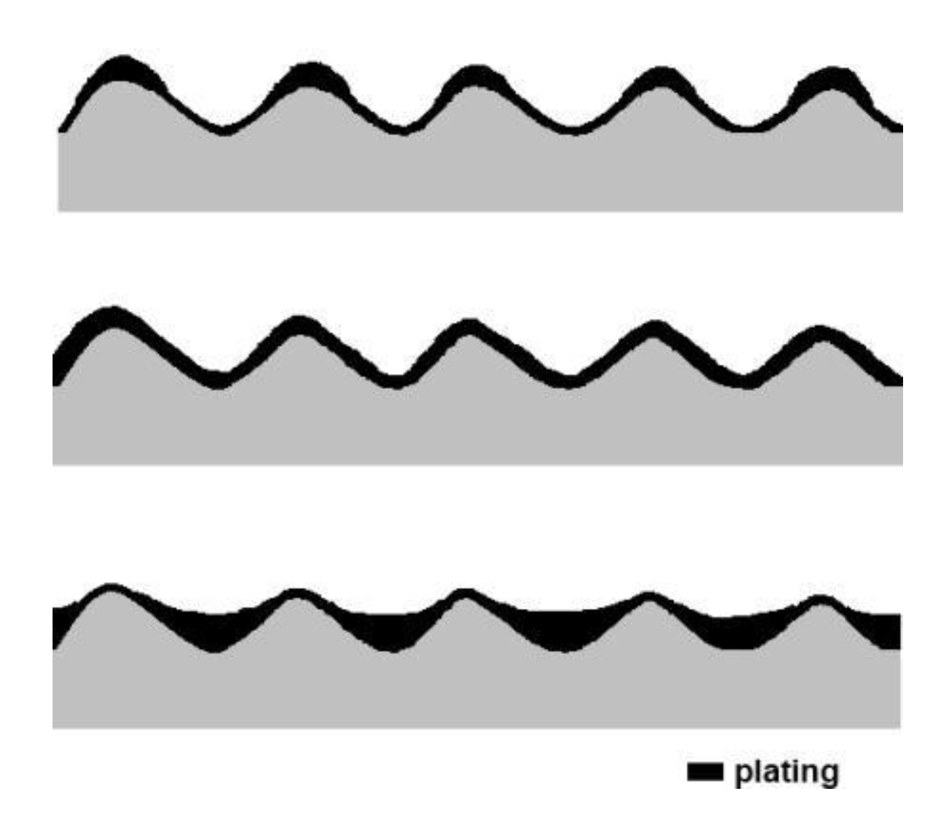
A similar phenomenon was also observed for hard gold layers by another author. One of his explanations for this phenomenon is the subsurface plastic deformation, which results in a deepening wear groove on the surface and the formation of buckles in the interlayers. Above these buckles, localized surface wear occurs. With repeated cycling, exposure of interlayer material eventually occurs at these sites. This occurrence is indicative of a local bulging of the interlayer through the final coating. It was found that with sufficiently thick and stiff interlayer this mechanism could be eliminated [6]. Another reason for this phenomenon is the dependence of the interlayer roughness on the thickness of interlayers. It was found that the interlayer roughness decreased with increasing thickness of up to 4 μm [35]. This is the result of the so-called leveling throw. The micro-throwing characteristics of electroplating can be influenced in the galvanic process. Apart from a leveling throw there is negative throw and geometric throw, Figure 27 [32].
Figure 27.
Schematic illustration of various micro throwing characteristics of electroplating [32].
Figure 27.
Schematic illustration of various micro throwing characteristics of electroplating [32].

3.3.6. Topography of Gold Coatings
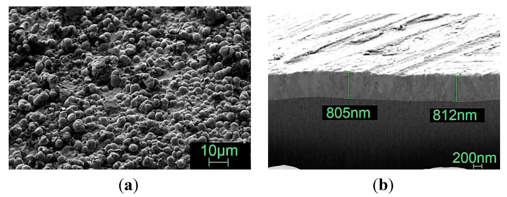
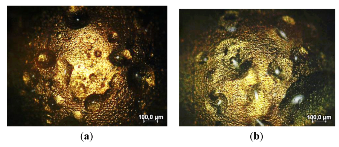
Once the comparable amount of nanoparticles is in the gold platings, the surface topography is also an important factor. A spherical structured surface (Figure 28a) seemed to be more favorable than a smooth surface (Figure 28b). The nanoscale particles used, the thickness of gold platings and the amount of nanoscale particles in gold platings were identical in both cases. The thickness of gold platings was 1 μm and the proportion of nanoscale particles was 1%. The reason for the large difference in the topography is the inhomogeneity of nanoscale particles, which can be controlled by dispersing methods. This is currently being investigated in another study and will be published in another paper at a later date.
Figure 28.
(a) Spherical structured surface (Lifetime: 400,000 cycles); (b) Smooth surface and Focused Ion Beam System (FIB) cross section of the coating (Lifetime: 55,000 cycles).
Figure 28.
(a) Spherical structured surface (Lifetime: 400,000 cycles); (b) Smooth surface and Focused Ion Beam System (FIB) cross section of the coating (Lifetime: 55,000 cycles).

3.3.7. Wear Patterns
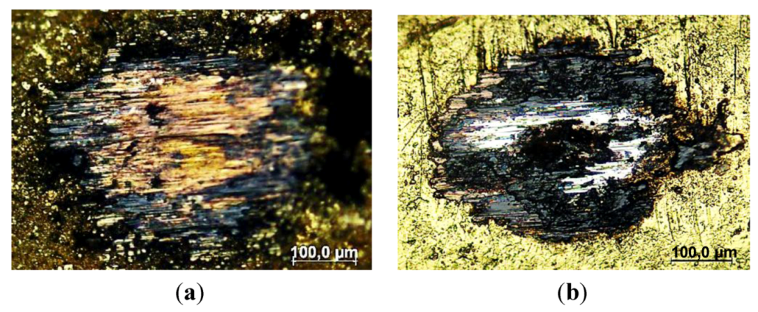
A close dependence between wear of gold and wear pattern can be observed at nanoscaled particles modified gold plating, Figure 29a,b. Figure 29 shows the wear area of two specimens after 50,000-cycle tests. The specimen with a low electrical resistance has a much lower wear thus a lot of gold can still be observed after a 50,000-cycle test, Figure 29a, speaks for a prevailing wear pattern. The specimen with a high contact resistance after a 50,000-cycle test has a much higher degree of wear and the zone of contact is completely covered with nickel of the interlayer and oxide indicated by the dark black color, Figure 29b. The investigation into the reason for the large difference in wear pattern of nanoscale particles enhanced gold coating is ongoing. Initial results do however indicate that the agglomeration of nanoscale particles, the particle distribution and particle size distribution in the coating play important roles in this process.
Figure 29.
(a) Microscopy of zone of contact (average depth of wear crater: 4 μm, contacts survive a 50,000-cycle test, nanoscale particles modified plating of 0.8 μm); (b) Microscopy of zone of contact (average depth of wear crater: 6 μm, contacts fail at 50,000-cycle, nanoscale particles modified plating of 0.8 μm).
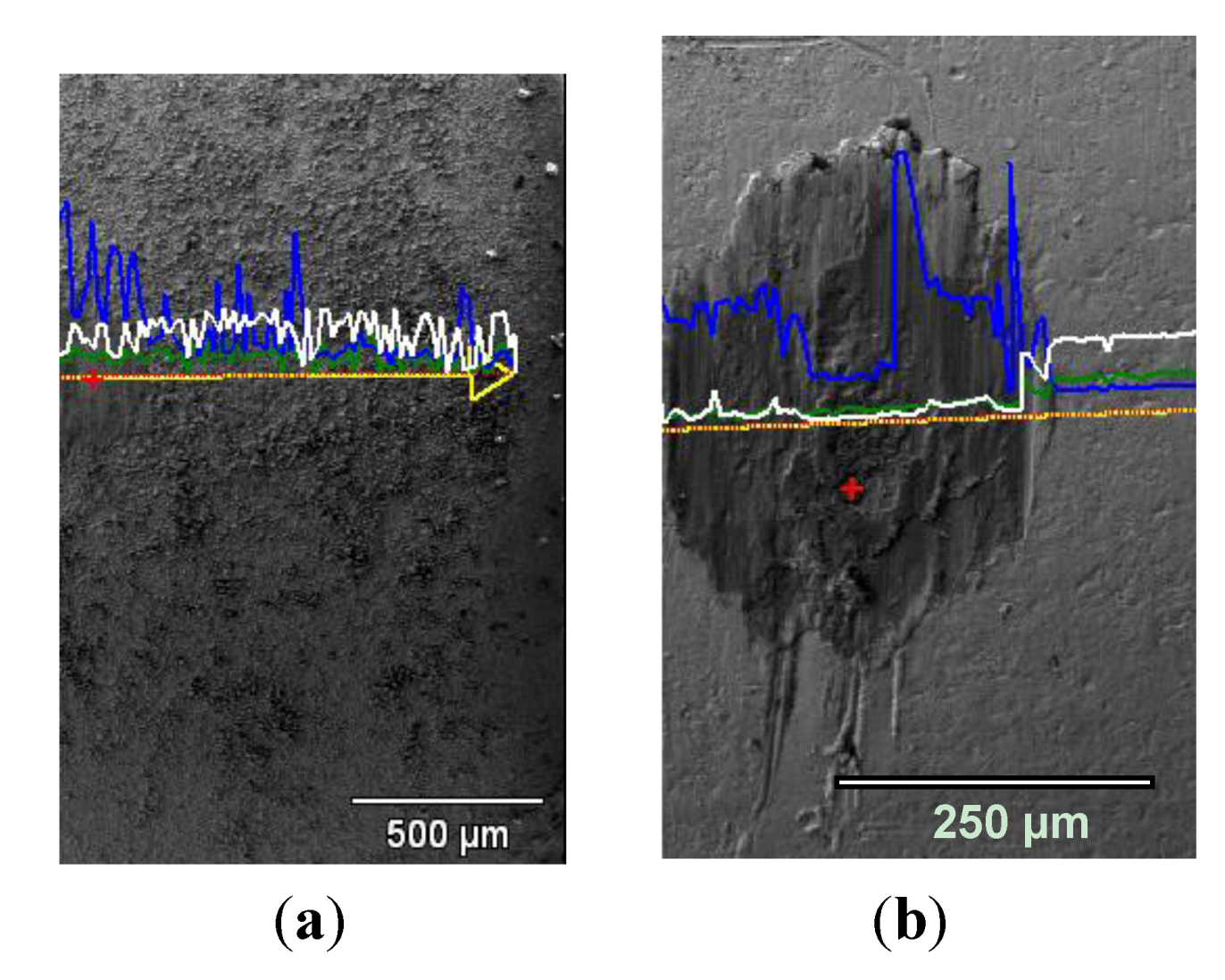
Wear resistance can be also analyzed with an energy dispersive X-ray spectroscopy (EDX). In the case of a high wear resistance, the line scan of gold distribution shows a large amount of gold in the zone of contact after a long term test, Figure 30a. In the case of a poor wear resistance of gold plating, the line scan of gold distribution shows a much smaller amount of gold in the zone of contact after a long term test, Figure 30b.
Figure 30.
(a) Line scans of gold in the zone of contact (white line). Due to the high wear resistance of gold plating, contact survives a more than 50,000-cycle test. Average depth of wear crater was 4 μm; (b) Line scans of gold in the zone of contact (white line). Due to the poor wear resistance, the gold plating is worn out after a 50,000-cycle test. Average depth of wear crater was 6 μm. Blue lines show the copper content and green lines show the nickel content. The same samples are used in Figure 28–Figure 30.
The relationship between surface topography and lifetime can vary. The high roughness has for example a reverse effect on the lifetime of hard gold platings. It was observed that a polish grinding of the surface substantially increased the lifetime of electrical contacts in wear and fretting corrosion tests. The reasons for this difference are conceivably the different wear mechanisms. The abrasive wear is the main wear mechanism for a rough surface and the adhesion wear is the dominant one for a smooth surface, which in turn seems to be more favorable for hard gold platings.
3.4. Wear of Corrosion Protecting Coatings
Motion due to mating and unmating of electrical contacts and due to different thermal expansion on both sides of electrical contacts leads to wear of corrosion protecting coatings. Once the coating is worn through, no protection exists for the base material. Therefore wear resistance of coatings is of extreme importance for electrically conductive surfaces, also in regard to the protection of corrosion and fretting corrosion. The importance of wear resistance for the lifetime of electrically conductive surfaces is obvious when regarding the correlation between the rate of wear and the lifetime of electrical contacts, Figure 31 and Figure 32. The best correlation was observed between the rate of wear and lifetime I, since the first instabilities occurred as soon as the first partial wear out of the over plate began. Lifetime II is a practical definition, but physically the definition is somewhat blurred. The degree of electrical resistance increase depends partly on the distribution of debris in the contact zone, especially in the case of precious metals. In this phase both wear and transportation of debris of the plate play an important role in the electrical resistance. Different wear patterns can be observed, which will be discussed later in this paper.
Figure 31.
Correlation between the rate of wear and lifetime I of electrical contacts with different coating materials.
Figure 31.
Correlation between the rate of wear and lifetime I of electrical contacts with different coating materials.
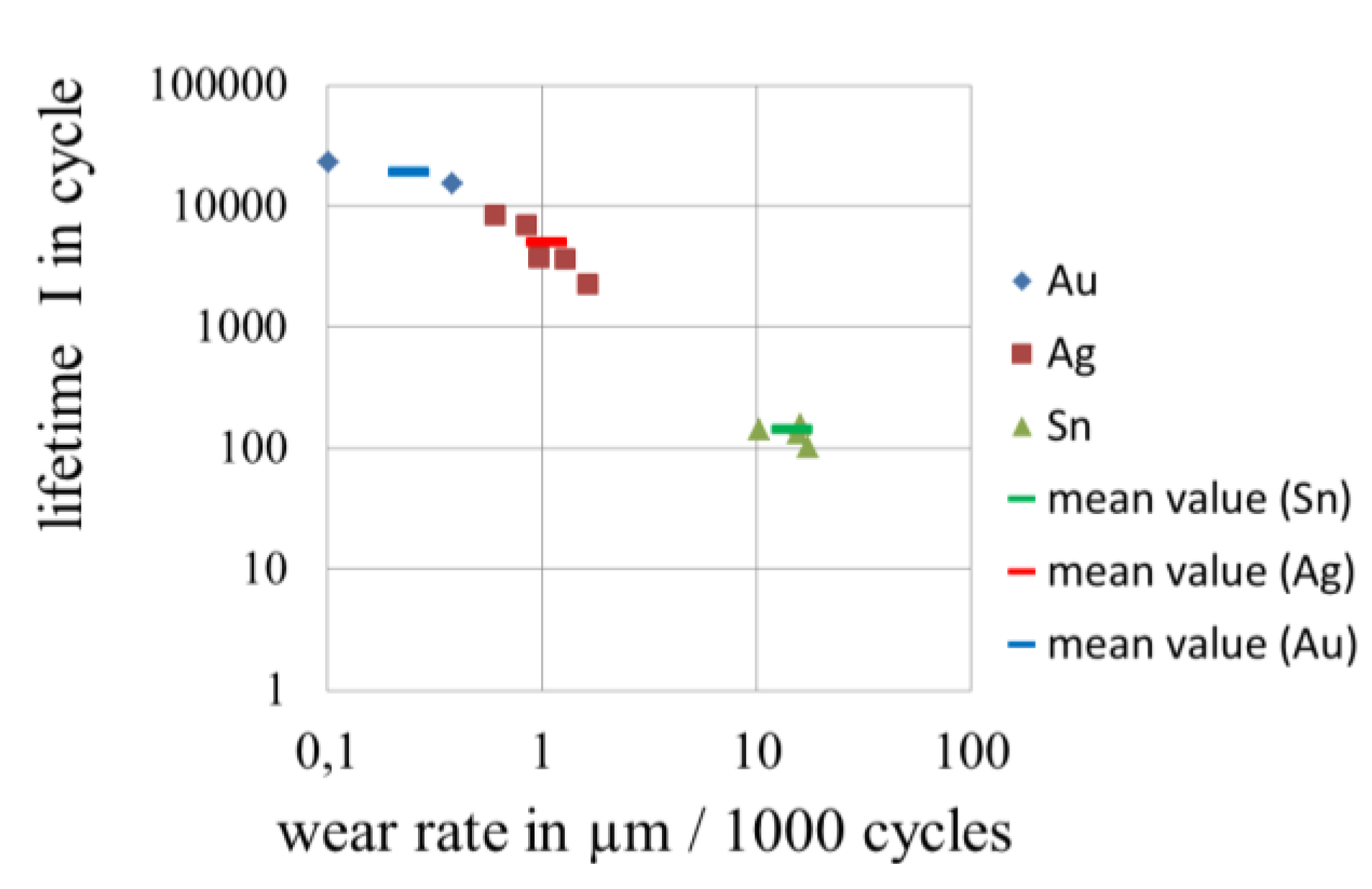
Figure 32.
Correlation between the rate of wear and lifetime II of electrical contacts with different coating materials.
Figure 32.
Correlation between the rate of wear and lifetime II of electrical contacts with different coating materials.

The lifetime of gold platings can be further improved by means of modification of gold platings with hard alloying elements or nanoscale particles. Figure 17 can therefore be interpreted as the effect of different nanoscale particles and alloying elements on the wear resistance of coatings.
The large range of lifetime is not due to a single runaway value but is verified by numerous measurements. The large lifetime range shows on the one hand the extensive potential of nanoscale particles modified gold platings and on the other hand, the large number of parameters in the process chain from generation of nanoscale particles to the nanoscale particles modified gold platings, which yet have to be investigated and characterized.
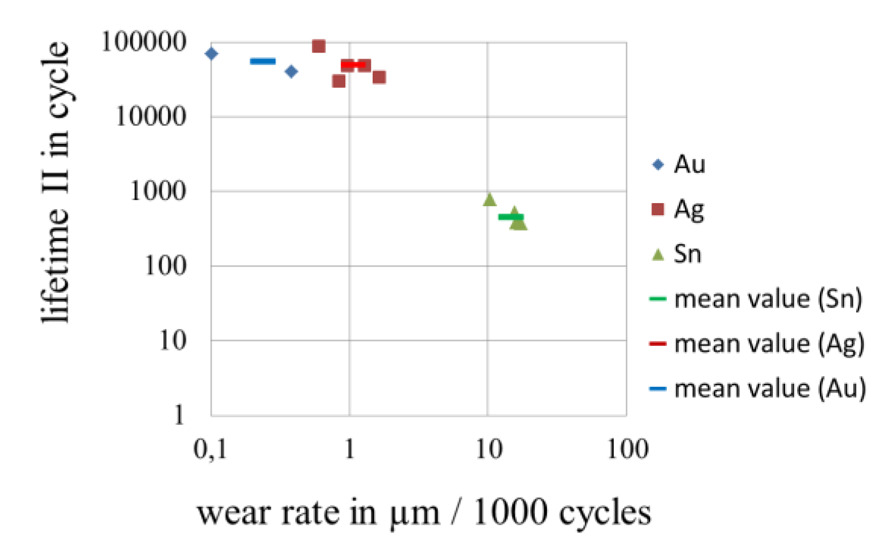
A very good correlation between the rate of wear of gold platings and the lifetime of electrical contacts in wear and fretting corrosion tests could be observed both for lifetime I and II, cf. Figure 33 and Figure 34.With increasing rate of wear (decreasing wear resistance) the lifetime of electrical contacts decreases. The rate of wear of pure (soft) gold is comparable with that of tin. Through the modification of gold, the rate of wear can be decreased by two to three decades and consequently the lifetime of electrical contacts can also be increased by more than two decades. This means that many measures used for improving bearing materials and experience gained in that area can also be applied for coating materials of electrical contacts. It is also to be noted that in terms of coefficient of friction the requirements for both bearing and electrical contacts are similar. A low coefficient of friction leads to a low insertion force for electrical connectors, which is desired.
Figure 33.
Correlation between rate of wear of gold platings and lifetime I of electrical contacts.

Figure 34.
Correlation between rate of wear of gold platings and lifetime II of electrical contacts.
Figure 34.
Correlation between rate of wear of gold platings and lifetime II of electrical contacts.

The fact that there is a very good correlation between the rate of wear and lifetime endorses the approach of the investigation. An increased wear resistance of the platings can lead to a long lifetime of electrical contacts with gold platings.
4. Conclusions
Gold alloys fundamentally possess the combination of desired properties for the overall protection of electrically conductive surfaces, having a very high corrosion resistance, a high wear resistance, a high fretting corrosion resistance and a high and stable electrical conductivity. The critical points with gold coating are the wear resistance and the material costs. We have shown the effectiveness of different ways of minimizing gold consumption for electrically conductive surfaces and how to improve the performance of the gold coating. Increased wear resistance can be achieved by means of hard nanoparticles and optimized alloy content in gold coatings.
Nanoparticle enhanced gold coatings displayed a higher potential than gold alloys. However, the statistical lifetime spread of these coatings is large and there are many more parameters with nanoparticles which influence the properties of coatings. Some of these parameters including particle materials, proportion of particles in coatings and peak size of particles were investigated in this paper. The investigation of other parameters e.g. particle size distribution and particle distribution in coating is still ongoing. A favorable wear pattern can be realized by the modification of material properties and by an adequate surface topography. A stable nickel interlayer is essential for a long lifetime. All the relationships between these parameters, electroplating process and the lifetime of electrical contacts require further investigation in order to reduce the lifetime spread. Once all these relationships have been discovered, it will be possible to obtain a highly wear resistant thin gold plating. The problem of porosity with thin platings can be resolved using treatment with SAMs.
Acknowledgments
The investigation was financially supported by the German Federal Ministry for Education and Research (BMBF), the European Union (EU, Project Nanogold) and the German State of Northrhine-Westfalia (NRW). RWTH Aachen, Enthone GmbH, Langenfeld, University of Paderborn, KME, Stolberg and Phoenix Contact, Blomberg supported the investigation with materials, specimens and measurements.
Conflict of Interest
The authors declare no conflict of interest.
References
- Landolt, D. Corrosion and Surface Chemistry of Metals; EPFL Press: Lausanne, Switzerland, 2007; pp. 227–274. [Google Scholar]
- Weast, R.C. CRC Handbook of Chemistry and Physics; CRC Press: Cleveland, OH, USA, 1978; pp. 141–146. [Google Scholar]
- Braunovic, M.; Konchits, V.V.; Myshkin, N.K. Electrical Contacts; CRC Press: Boca Raton, FL, USA, 2007; pp. 78–79. [Google Scholar]
- Jostan, J.L.; Mussinger, W.; Bogenschütz, A.F. Korrosionsschutzin der Elektronik (in German); Eugen G. Leuze Verlag: Saulgau, Germany, 1986; pp. 12–50. [Google Scholar]
- Braunovic, M. Fretting in electrical/electronic connections: A review. In IEICE Trans.; 2009; Volume 92-C, pp. 982–991. [Google Scholar]
- Antler, M. Tribologyof Electronic Connectors, in Electrical Contacts—Principles and Applications; Marcell Dekker: New York, NY, USA, 1999; pp. 332–364. [Google Scholar]
- Song, J. Hochschule Ostwestfalen-Lippe University of Applied Sciences, Lemgo, Germany. Unpublished work, 2011.
- Kfz-Steckverbinder-Prüfvorschrift LV 214 (in German); Volkswagen AG: Wolfsburg, Germany, 2010.
- Ben Jemaa, N.; Swingler, J. Correlation between Wear and Electrical Behaviour of Contact Interfaces during Fretting Vibration. In Proceedings of ICEC, Fredericton, NB, Canada, August 13–16, 2006.
- McBride, J.W. On the Relationship between Surface Wear and Intermittency during Fretting in Electrical Contacts. In Proceedings of Holm Conference 2006, Montreal, QC, Canada, September 25–27, 2006.
- Song, J.; Koch, C. Wear Patterns and Lifetime of Electric Contacts. In Proceedings of Holm Conference 2008, Orlando, FL, USA, October 27–29, 2008.
- Gold Demand Trends. Available online: http://www.gold.org/investment/research/regular_reports/gold_demand_trends/ (accessed on 12 November 2012).
- Gold Survey 2010. Available online: www.gfms.co.uk (accessed on 12 November 2012).
- Christian, H.; Christopher, W.C. Recycling of gold from electronics: Cost-effective use through “Design for Recycling”. Gold Bull. 2010, 43, 209–220. [Google Scholar] [CrossRef]
- Glüsing, J.; Höges, C.; Jung, A.; Meyer, C.; Rao, P. Der Fluch des Goldes (in German). Der Spiegel. 17 March 2008. Available online: http://www.spiegel.de/spiegel/print/d-56240589.html (accessed on 12 November 2012).
- Endres, B. Edelmetallbeschichtungen für die Verbindungstechniken in derElektronik (in German). Galvanotechnik 2006, 97, 2636–2641. [Google Scholar]
- AMP, Golden Rules: Guidelines for the Use of Gold on Connector Contacts; AMP Incorporated: Harrisburg, PA, USA, 1996.
- Vinaricky, E. Elektrische Kontakte, Werkstoffe und Anwendungen (in German); Springer: Berlin, Germany, 2002; pp. 151–154. [Google Scholar]
- Hornyak, G.L.; Tibbals, H.F.; Dutta, J.; Moore, J.J. Introduction to Nanoscience & Nanotechnology; CRC Press: Boca Raton, FL, USA, 2009; pp. 1098–1099. [Google Scholar]
- Slocum, A.H. Precision Machine Design; SME: Dearborn, MI, USA, 1992; pp. 425–440. [Google Scholar]
- Abys, J.A. Self Assembled Monolayers—Application to Surface Finishing for Electronics; A Presentation of Cookson Electronics, Enthone Inc.: West Haven, CT, USA, 2011. [Google Scholar]
- Connectors for Electronic Equipment—Tests and Measurements; German Institute for Standardization: Berlin, Germany, 2003.
- ASTM B 845: Standard Guide for Mixed Flowing Gas (MFG) Tests for Electrical Contacts; ASTM: West Conshohocken, PA, USA, 1997.
- DIN 50018, Testing in a Saturated Atmosphere in the Presence of Sulfur Dioxide; German Institute for Standardization: Berlin, Germany, 1997.
- ISO 3231, Determination of Resistance to Humid Atmospheres Containing Sulfur Dioxide; ISO: Geneva, Switzerland, 1997.
- ASTM G87, Standard Practice for Conducting Moist SO2 Tests; ASTM: West Conshohocken, PA, USA, 2002.
- DIN EN 60068-2-52, Environmental Testing-Salt Mist, Cyclic (Sodium Chloride Solution); German Institute for Standardization: Berlin, Germany, 1996.
- ASTM B 735-06, Standard Test Method for Porositiy in Gold Coatings on Metal Substrates by Nitric Vapor; ASTM: West Conshohocken, PA, USA, 2011.
- IPC-TM-650, Test Methods Manual, Association Connecting Electronics Industries; IPC: Bannockburn, IL, USA, 1997.
- Sawitzki, F. Einflussparameter von Reibkorrosionsuntersuchungen (in German).
- Wang, L. Analyse der Einflussparameter und Wirkungsmechanismen von Nanopartikeln in der Oberflächenschutzschicht elektrischer Kontakte (in Germany).
- Antler, M. Materials, Coatings, and Platings, in Electrical Contacts—Principles and Applications; Marcell Dekker: New York, NY, USA, 1999; pp. 403–432. [Google Scholar]
- Song, J.; Koch, C.; Wang, L.; Stopic, S.; Bogovic, J.; Friedrich, B.; Möbius, A.; Fuhrmann, A. Nanotechnologie in der elektrischen Verbindungstechnik (in German). In Elektrische und Optische Verbindungstechnik; Labor für Feinsystemtechnik, Hochschule Ostwestfalen-Lippe University of Applied Sciences: Lemgo, Germany, 2011; pp. 61–66. [Google Scholar]
- Song, J.; Zibart, A.; Koch, C.; Shmidt, L.; Wang, L. Einfluss von Goldlegierungsarten und Anteilen auf die Lebensdauer von elektrischenKontakten (in German). In Elektrische und Optische Verbindungstechnik; Labor für Feinsystemtechnik, Hochschule Ostwestfalen-Lippe University of Applied Sciences: Lemgo, Germany, 2011; pp. 25–34. [Google Scholar]
- Shmidt, L. Optimierung der Oberflächen für elektrische Kontakte (in German).
© 2012 by the authors; licensee MDPI, Basel, Switzerland. This article is an open-access article distributed under the terms and conditions of the Creative Commons Attribution license (http://creativecommons.org/licenses/by/3.0/).
Share and Cite
MDPI and ACS Style
Song, J.; Wang, L.; Zibart, A.; Koch, C. Corrosion Protection of Electrically Conductive Surfaces. Metals 2012, 2, 450-477. https://doi.org/10.3390/met2040450
AMA Style
Song J, Wang L, Zibart A, Koch C. Corrosion Protection of Electrically Conductive Surfaces. Metals. 2012; 2(4):450-477. https://doi.org/10.3390/met2040450
Chicago/Turabian StyleSong, Jian, Liangliang Wang, Andre Zibart, and Christian Koch. 2012. "Corrosion Protection of Electrically Conductive Surfaces" Metals 2, no. 4: 450-477. https://doi.org/10.3390/met2040450