Article

Dynamic Behavior of Hybrid APM (Advanced Pore Morphology Foam) and Aluminum Foam Filled Structures

1
Department for Powder technology, Fraunhofer Institut IFAM, Bremen 28359, Germany
2
Department of Mechanics, Politecnico di Milano, Milano 20156, Italy
3
MUSP Laboratory, Piacenza 29122, Italy
*
Author to whom correspondence should be addressed.
Metals 2012, 2(2), 211-218; https://doi.org/10.3390/met2020211
Submission received: 3 May 2012 / Revised: 29 May 2012 / Accepted: 11 June 2012 / Published: 20 June 2012

Abstract

:
The aim of this work is to evaluate the effect of different densities of hybrid aluminum polymer foam on the frequency behavior of a foam filled steel structure with different ratios between steel and foam masses. The foam filled structure is composed of three steel tubes with a welded flange at both ends bolted together to form a portal grounded by its free ends. Structure, internal and ground constraints have been designed and manufactured in order to minimize nonlinear effects and to guarantee optimal constraint conditions. Mode shapes and frequencies were verified with finite elements models (FEM) to be in the range of experimental modal analysis, considering the frequency measurement range limits for instrumented hammer and accelerometer. Selected modes have been identified with suitable modal parameters extraction techniques. Each structure has been tested before and after filling, in order to compute the percentage variation of modal parameters. Two different densities of hybrid aluminum polymer foam have been tested and compared with structures filled with aluminum foams produced using the powder compact melting technique. All the foam fillings were able to suppress high frequency membrane modes which results in a reduction of environmental noise and an increase in performance of the components. Low frequency modes show an increase in damping ratio only when small thickness steel frames are filled with either Hybrid APM or Alulight foam.

1. Introduction

The use of aluminum foam as a filling for structural components is intended to improve their dynamic behavior, increase impact energy absorption, etc. [1]. In the machine tools field, the structures are generally designed by means of finite elements models (FEM) of the whole machine (basement, ram, spindle, etc.) to obtain the desired dynamic behavior, the desired material savings and to avoid unwanted vibrations [2]. If the virtual model is taken as a starting point (as in the work here described), the technological problems for the realization of the designed structure must be solved. In the realization of a ram with aluminum foam filling [3], as an example, the component must be grinded and heat-treated. As the foaming process needs to take the ram to up to 650 °C, it is difficult to obtain the required tolerances. Therefore the use of aluminum foam fillings adds a degree of freedom to the structure design but also introduces some technological issues.
While it is well known in scientific literature that aluminum foam has a greater loss factor than its base bulk material [1], there is, however, a lack of reports on the dynamic behavior of aluminum and Hybrid APM filled structures, as a function of hollow structure characteristics. In this paper attention is focused on foam filling of a simple structure (a portal) in order to obtain guidelines for the design of more complex components considering two important aspects: the dynamic behavior (experimental modal analysis) and the foaming temperature. A very promising material for the realization of filled structures with strict tolerances, is the hybrid APM foam [
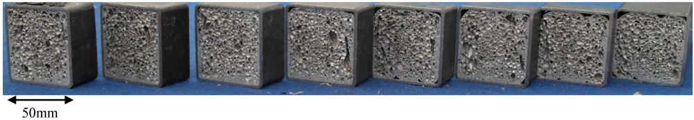
4] which will be compared to aluminum foam prepared by powder metallurgical (PM) route. To manufacture hybrid APM foam, aluminium foam spheres are produced by foaming a granulated precursor material and subsequently coated with a thermally activated adhesive which contains a chemical foaming agent. The coated granules are then poured into the hollow structures which have to be filled. During a subsequent heat-treatment at moderate temperatures (e.g., 120 to 180 °C) the adhesive melts, foams up and cures. Thus, filling the hollow structures with hybrid APM foam is very easy and the thermal load applied to the structure is much less than in the traditional foam filling process.
Different types of foam fillings will be considered and compared to the original empty structure and then to each other, in order to evaluate their performances at different frequencies.

2. Experimental Procedure

2.1. Selection of Structure Characteristics

As this work focuses on mechanical and technological aspects, the chosen structure is intentionally simple but it exhibits a wide range of frequency modes and is representative for the design of more complex components. The portal is a hyperstatic structure with simple mode shapes at low frequency (below 100 Hz), structural modes at mid-range frequencies (100–800 Hz) and membrane modes at higher ones (greater than 1000 Hz).
The main dimensions and shape of the structure were defined by means of FEM analysis in order to meet some constraints:
  • Impact test [5] was chosen as a measurement technique for the determination of the dynamic stiffness of the structure. Therefore the first eigenfrequency of the frame has to be higher than 20 Hz;
  • The structure has to show a wide range of eigenfrequencies from low frequency (involving the whole structure) to mid-range frequencies (complex shaped modes) and to higher ones (involving only the membranes of the tubes) in order to obtain a complete overview of the fillings effect;
  • Ground constraints compliance has to be negligible;
  • The portal has to be easily filled using different filling techniques.
The ABAQUS FEM model was built using S4R shell elements for the thin walls of the tubes and C3D8 brick elements for the connection plates and for the washers, average mesh size is less than 5 mm. The constraints were modeled using the ABAQUS tie constraint to reproduce the bolt coupling.
As a result the structure elements are made up of three identical tubular elements (Figure 1, Figure 2, Figure 3). Structure span is about 500 mm × 500 mm, and tube section is 50 mm × 50 mm, with 2 and 4 mm wall thickness. The two tube wall thicknesses were chosen to study the effect of the foam fillings. For the first mode (see below) the tubes with 4 mm thickness have more than the double stiffness so the main idea is that the various types of foam fillings will have a decreasing effect as tube thickness increases.
Figure 1. Hybrid APM foam filled tube cross sections.
Metals 02 00211 g001
Figure 2. Aluminum foam filled tube cross sections.
Metals 02 00211 g002
Figure 3. (a) Experimental setup for the frequency response functions (FRF) estimation along with accelerometer and impact point positions. Ground and internal constraints; (b) Example of a measured FRF in black (H1 estimator) and corresponding identified FRF in red, for mid-frequency modes.
Metals 02 00211 g003

2.2. Filling of the Tubes

For filling the portal structures with hybrid APM foam, each single tube element was cleaned with alcohol and then dried. The tube was then filled with the coated APM spheres and two endplates were mounted. The filled tubes were put horizontally into a furnace which was preheated to 160 °C and were kept at this temperature for 3 hours, to effect the foaming and curing of the adhesive. Then the tubes were removed from the furnace and allowed to cool in air. In Figure 1 the cross sections of a Hybrid APM filled tube are depicted.
For filling with aluminum foam the steel tubes were left untreated. Alulight Foaminal AlSi10 commercial precursor was weighted in order to obtain a foam density of about 550 kg/m3 and placed horizontally inside the tube. Two bolted steel endplates were used in order to limit foam expansion. The tubes were foamed horizontally in an air convection furnace preheated at 700 °C for about 11.5 minutes (2 mm thick tubes) or 13.5 minutes (4 mm thick tubes) and then cooled in a compressed air flux. Figure 2 shows the cross sections of an aluminum foam filled tube.

2.3. Experimental Setup

The setup shown in Figure 1 has been used for the determination of mid-frequency modes as a soft tip is mounted on the instrumented hammer. The middle and high (membrane) frequency modes were measured with a lighter hammer with harder tip to excite higher frequencies [5].
The modal analysis performed was carried out with PCB® instrumented hammers and accelerometers (086C04, 086D05, 352C23, 352A24) and National Instruments® Data Acquisition Device (2x9234 with cDAQ 9178). The frequency response functions (FRF) were computed with the commonly used H1 estimator [5].

2.4. Modal Parameter Identification

The modal parameter identification was carried out by means of the manual selection of the peaks of interest. For each peak one of the three parameter identification algorithms [5] was selected (peak-amplitude has been used in most of cases). The identification was carried out one peak at a time in a recursive way to separate the various contributions. An example of the result of this identification procedure is reported in Figure 3 for mid-frequency modes.

2.5. Designed Experiment

In order to perform the analysis of the dynamic behavior, only two modes were selected: one in the low-frequency range (labeled 90 Hz) and the second in the mid-frequency range (labeled 700 Hz). As will be seen later, the high-frequency modes (membrane modes) disappear as the structures are filled so a quantitative comparison is not needed. The selected modes shapes are reported in Figure 4 for the 2 mm tube thickness and in Figure 5 for the 4 mm ones.
Figure 4. Modal parameters for the 2 mm tube wall thickness (low and mid frequency modes) and corresponding mode shapes. False colors represent normalized displacements.
Metals 02 00211 g004
Figure 5. Modal parameters for the 4 mm tube wall thickness (low and mid frequency modes) and corresponding mode shapes. False colors represent normalized displacements.
Metals 02 00211 g005
As described above, the designed experiments include:
  • Two levels of tube wall thickness-2 mm and 4 mm;
  • Three types of fillings:
    • Hybrid APM low density foam (~490 kg/m3) (APM L);
    • Hybrid APM high density foam (~590 kg/m3) (APM H);
    • Alulight Foaminal foam (~550 kg/m3) (Alulight foam or Alulight);
  • Three replicates for every parameter set with a total of 18 portal structures.
Every structure was measured using the modal analysis technique before and after the filling process with estimation of the modal parameters for the two modes. The performance indicators are the percentage variations of the modal parameters for the filled structure with respect to the corresponding empty one: mode frequency, dynamic stiffness, modal mass and damping ratio (defined as the ratio between the damping factor and the critical damping factor) [5].

3. Results and Discussions

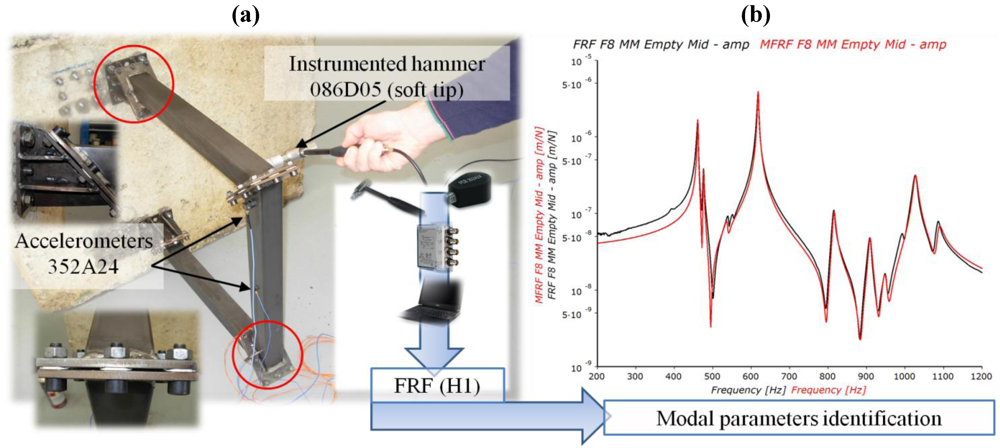
The analysis was carried out for each skin thickness and selected mode (low and mid frequency). As can be seen in 
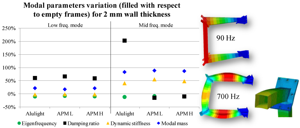
Figure 4, the three fillings have the same influence on the modal parameters of the low frequency mode for the 2 mm thickness tubes. The damping ratio increases of 60 to 65%, whereas the dynamic stiffness is slightly reduced. It is obvious that the modal mass increases as the filling is introduced. As a result, the eigenfrequency decreases.
In the mid-frequency mode for the same tubes thickness, it is possible to see that Alulight foam filling strongly increases the damping ratio, while hybrid APM (both low and high densities) reduce the ratio. It is possible to justify a reduction in the damping ratio considering that it is defined as the ratio between the damping coefficient c over the critical damping coefficient: Metals 02 00211 i001. If the damping coefficient is unchanged and the mass increases, the damping ratio decreases.
Furthermore, it is important to note that the dynamic stiffness increases for the mid-frequency mode, whereas it is nearly unchanged at low frequency. Lastly, modal mass is nearly twice the corresponding empty structures for the mid-frequency mode.
The behavior of the damping ratio, modal mass and dynamic stiffness for the two modes can be explained by their shapes. The low frequency one is a straight line from the constraint to the free end (horizontal tubes in Figure 3) whereas the second is a parabola starting and ending at near-zero deformation. The hybrid APM filling types are bonded (glued) to the skin whereas the aluminum foam is not bonded [6]. If such a bonding is not present, a 700 Hz parabolic shape mode enables a great energy dissipation (friction) while mass and stiffness exhibit the same behavior. This is the most promising hypothesis for the explanation of +200% of damping ratio.
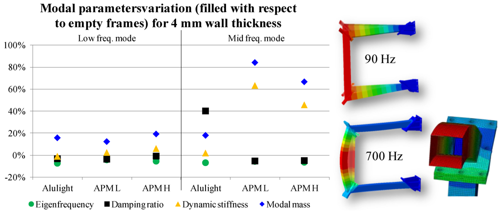
Considering the low frequency mode for the 4 mm thickness tubes, it can be seen (Figure 5) that there is a slight reduction in both the eigenfrequency and damping ratio with an increase of about 15% in modal mass. The dynamic stiffness depends on the filling type: it is nearly unchanged for Alulight foam and increases with hybrid APM foam density even if change values are close to zero.
The mid-frequency mode (4 mm skin) exhibits, for hybrid APM, the same behavior reported in Figure 4, whereas Alulight foam increases the damping ratio of about 40%. The latter could also be explained by the lack of bonding as for the 2 mm tubes structure. The main difference between the mid frequency modes shape for 2 and 4 mm tubes, is that the former exhibits skin rounding, and the latter does not. As Alulight foam fillings are not bonded to the skin, a greater effect of filling on modal parameters in the 2 mm case is expected. As can be seen when comparing Figure 4 and Figure 5, the dynamic mass and stiffness for hybrid APM are the same for the two wall thicknesses, while Alulight foam exhibits a scaled performance (of about one fifth).
Finally, the dynamic behavior of the empty structures is characterized by a little number of modes from 1500 Hz up that involve only the tube skin (called membrane modes). These modes disappear when any of the three types of filling is introduced in the tubes.
FEA analysis performed on the structures shows a good agreement with measured low-frequency modes (errors are within ±5%) in terms of modal shape and frequency. As mode frequency increases, the FEM prediction is not reliable, as local deformations are not well predicted in FEM analysis due to geometry and material simplifications.

4. Conclusions

The lack of documentation on the design of structural components in order to maximize the effect of foam filling was the pivotal reason for this work. The most important conclusion (revealed in hindsight) is that it is not possible to define a general procedure as the modes shape have a great influence on the performance of the filling. In the case considered in this study, the three foam fillings tested have the same influence on modal parameters only if vibration amplitudes are great or mode shape involve the filling itself (i.e., skin rounding). A partially unproven hypothesis is that the bonding of the filling has a great influence on the damping ratio of high frequency modes, whereas the nature of the filling influences all modal parameters.
Hybrid APM exhibits stable results in terms of modal parameters, whereas unbonded Alulight foam needs a mode shape that involves the whole filling to maximize the performance. As noted above, if no bonding is present and the mode shape does not involve the filling, damping ratio is increased while the other parameters remain almost unchanged.
Another important result is that both foam fillings (Alulight or hybrid APM) were able to suppress the membrane modes. This expected phenomenon results in a reduction of environmental noise and an increase in performance of the component.
Finally, the foaming temperature must be considered. In certain applications, the mechanical component has tolerances that must be respected after the foaming process. In this way hybrid APM has a great advantage as the foaming temperature is 120–180 °C, whereas Alulight precursor must be heated to up to the melting point of the precursor material, usually about 650 °C. A heat treatment involving a fast heating ramp up to 650 °C and a subsequent cooling phase can produce severe thermal deformations unacceptable in applications characterized by narrow tolerances such as the one described in [2]. In these types of applications, hybrid APM fillings can be considered an attractive alternative, because the low temperature foaming phase is easily controllable and nearly deformation free.

Conflict of Interest

The authors declare no conflict of interest.

References

  1. Ashby, M.F.; Evans, A.G.; Fleck, N.A.; Gibson, L.J.; Hutchinson, J.W.; Wadley, H.N.G. Metal Foams—A Design Guide; Butterworth-Heinemann: Oxford, UK, 2000. [Google Scholar]
  2. Altintas, Y. Manufacturing Automation; Cambridge University Press: Cambridge, UK, 2000. [Google Scholar]
  3. Bernasconi, A.; Monno, M.; Schiavi, B.; Mussi, V. Design of a machine tool ram with sandwichpanels and aluminum foam core. In Proceedings of IX AITeM Conference, Torino, Italy, 7–9 September 2009.
  4. Weise, J.; Ruparelia, D.H.; Wichmann, M.; Baumeister, J. Investigation of the mechanical behaviour of particulate aluminum-epoxy hybride foams in dependence upon the metal and polymer content. In Proceedings of the CELLMAT, Dresden, Germany, 27–29 October 2010.
  5. Ewins, D.J. Modal Testing: Theory, Practice and Application, 2nd ed; Research Studies Press: Baldock, UK, 2000. [Google Scholar]
  6. Baumeister, J. Methods for filling hollow structures with aluminum foam. Mater. Sci. Forum 2010, 884, 61–66. [Google Scholar] [CrossRef]

