
Effects of Full Chain Processes on the Performance of 316L Stainless Steel Composite by Fused Deposition Modeling and Sintering
1
School of Intelligent Manufacturing and Electrical Engineering, Guangzhou Institute of Science and Technology, Guangzhou 510540, China
2
College of Engineering, South China Agricultural University, Guangzhou 510642, China
*
Author to whom correspondence should be addressed.
Metals 2023, 13(12), 2022; https://doi.org/10.3390/met13122022
Submission received: 21 November 2023
/
Revised: 15 December 2023
/
Accepted: 16 December 2023
/
Published: 17 December 2023
Abstract
:Fused deposition modeling and sintering (FDMS) is a novel 3D printing technique that combines fused deposition modeling with catalytic debinding and sintering processes to enable the rapid production of metal parts with low energy consumption and costs. Firstly, a 316L/POM composite filament is prepared. Subsequently, test specimens are printed using a fused deposition modeling (FDM) printer, followed by catalytic debinding and sintering processes to create dense metal parts. The process parameters show an influence on the part structure and, subsequently, the properties, and this study examines the microstructural characteristics of the 316L/POM composite filament at each process stage. Using tensile strength as the indicator, an orthogonal experiment is designed to identify suitable combinations of process parameters. Experimental results demonstrate that the FDMS process can manufacture 316L stainless steel parts; moreover, they influence the structure and, consequently, the mechanical behavior, as these are strongly related. By appropriately adjusting the process parameters, this method can be suitable for applications requiring functional parts with less stringent strength requirements.
1. Introduction
Three-dimensional printing technology is a type of rapid prototyping technology that utilizes the concept of discretization. It uses materials such as plastics or powdered metals to manufacture three-dimensional objects through layer-by-layer construction and accumulation using printing equipment [1,2,3]. Currently, there are several 3D printing technologies that enable the fabrication of metal components [4,5], such as metal powder bed fusion [6] and direct energy deposition [7]. Metal powder bed fusion technology is applicable to various types of metal materials, such as titanium alloys, aluminum alloys, and stainless steel [8]. It enables high-precision manufacturing and the creation of extremely delicate structures and components. This technology encompasses direct energy deposition [9], powder bed fusion [10], and sheet lamination [11]. Powder bed fusion technology minimizes material waste by utilizing only the necessary materials for the production of the required parts [12]. Direct energy deposition technology utilizes high-power lasers or electron beams to melt metal materials, resulting in fast construction speeds and reduced manufacturing periods compared to traditional manufacturing methods, thus improving the production efficiency [13]. Direct energy deposition technology includes processes such as laser engineered net shaping (LENS) [14], laser metal deposition (LMD) [15], and electron beam additive manufacturing (EBAM) [16], allowing for the production of complex parts with precise geometries. The accurate melting and deposition process enables meticulous structural detailing and accurate size control. All aforementioned metal 3D printing technologies utilize elevated temperatures (achieved through either electron beams or lasers) to selectively melt metal materials, enabling layer-by-layer additive manufacturing and the production of three-dimensional structures, which entail high energy consumption and elevated production costs.
The metal additive manufacturing technique, which combines fused deposition modeling (FDM), catalytic debinding, and sintering processes, is applied to fabricate metal parts using metal/polymer composite materials [17]. This method demonstrates considerable economic advantages concerning equipment costs, material costs, and energy consumption, thereby introducing a novel approach for the rapid prototyping of high-melting-point metal materials [18,19]. He et al. [20] examined the impact of diamond parameters on diamond tools fabricated using fused deposition modeling (FDM) and sintering technology. The utilization of diamond materials in tool manufacturing offers exceptional mechanical properties, such as high hardness and wear resistance, making it a promising choice for various industrial applications. Wen et al. [21] investigated the anisotropy in tensile properties and the fracture behavior of 316L stainless steel parts manufactured by fused deposition modelling and sintering. The present study conducts an extensive analysis and investigation of the three key stages involved in FDM 3D printing, catalytic debinding, and the sintering of 316L/POM composite materials. It explores the process principles of metal 3D printing technology based on FDM, providing valuable insights for its industrial utilization and promoting relevant research within the realm of cost-effective metal additive manufacturing.
The fused deposition modeling (FDM) and sintering processes are complex, involving multiple steps, each with a range of process parameters. Therefore, it is imperative to conduct a comprehensive analysis and investigation of the process parameters for each step. In the printing phase, crucial process parameters such as the nozzle temperature, print bed temperature, layer thickness, and infill density exert significant influences on the mechanical properties of the printed prototype. Fine tuning these printing parameters plays a pivotal role in ensuring optimal outcomes in subsequent process stages. In the catalytic debinding process, the catalyst flow rate and debinding temperature emerge as critical factors determining the effectiveness of debinding. Selecting appropriate process parameters becomes indispensable in guaranteeing a high-quality debound prototype. Similarly, in the high-temperature sintering phase, different sintering temperatures exhibit profound impacts on the mechanical properties and density of the final product. This study undertakes a systematic analysis and exploration of the process parameters encompassing the FDM 3D printing, catalytic debinding, and sintering stages of a 316L/POM composite material. Through the utilization of an orthogonal experimental design, this research aims to identify the most suitable process parameters and elucidate the underlying principles governing metal 3D printing based on FDM technology.
By meticulously investigating and optimizing the process parameters, this research endeavors to enhance the overall understanding of the FDM-based metal 3D printing process. The findings of this study have far-reaching implications for the advancement and application of additive manufacturing technologies, enabling the production of high-quality, mechanically robust prototypes with superior dimensional accuracy and material properties.
2. Materials and Methods
2.1. Materials
The experimental materials’ information and proportions are shown in Table 1. The 316L stainless steel powder used in this experiment had a particle size ranging from 30 μm to 50 μm, with a particle size characteristic of D90. Polyoxymethylene (POM) was selected as the main component of the binder, with a melt flow index of 18 g/10 min (230 °C/2.16 kg) [22]. A certain amount of PP was added to improve the flowability of the filament [23], and a certain quantity of zinc oxide was added as a thermal stabilizer [24]. This allowed for increased heat absorption by an equivalent mass of polypropylene (PP) and polyoxymethylene (POM). Finally, a mixture of dioctyl phthalate (DOP) and dibutyl phthalate (DBP) was added to enhance the flexibility of the filament [25].
The filament preparation device is shown in the Figure 1. In the initial step, the mixture of formaldehyde particles and POM powder was heated at 80 °C for 4 h. Subsequently, the weighed materials were uniformly mixed in a high-speed mixer. The resulting mixture was then introduced into a twin-screw extruder, with the temperatures of each section set as follows: 165 °C for the first section, 180 °C for the second section, and 170 °C for the third and fourth sections. The twin-screw extruder operated at a speed of 180 r/min, while the feeding frequency was set at 7 r/min. The extruded filament was cooled by submerging it in cold water and then dried before being pelletized using a cutting machine. Finally, the obtained pellets were fed into a single-screw extruder, in which the first section temperature was set at 160 °C, the second section temperature at 178 °C, and the third section temperature at 160 °C. The single-screw extruder operated at a speed of 13.45 r/min, and the traction speed was 16.75 m/min. After the filament had cooled and achieved dimensional stability, it was wound onto a spool.
2.2. Experimental Procedure
The manufacturing workflow of FDMS comprises three steps, FDM printing, catalytic debinding, and sintering, each of which has a critical impact on the final part quality [26,27]. The experimental procedure was conducted as follows. First, an improved FDM 3D printer, specifically designed for metal/polymer composite material printing, was used. Based on the sliced information from the CAD model, the metal/polymer composite material was deposited layer by layer using the 3D printer under computer program control. The deposition temperature was set slightly higher than the melting point of the polymer component. The printing parameters were set according to Table 2 and the filling rate referred to the ratio of the internal space occupied by the infill material during the printing process.
Subsequently, the green specimens were subjected to a STZ-MP-15 degreasing furnace to obtain debound specimens. The STZ-MP-15 degreasing furnace was developed by Shenzhen Xingte Aokai Technology Co., Ltd. (Shenzhen, China). During the catalytic debinding process, the polyoxymethylene (POM) binder was catalytically decomposed and removed, while a small amount of residual binder was retained to maintain the shape of the debound specimens, preventing deformation or collapse. Finally, the debound specimens were sintered at a high temperature under argon gas protection, enabling the removal of the remaining binder and achieving metallurgical bonding between the metal particles to form metal parts. The Mg 30/30/30 high-temperature sintering furnace was manufactured by Shenzhen Mega Vacuum Furnace Co., Ltd. (Shenzhen, China). The entire process is illustrated in Figure 1.
In the orthogonal experiment, the selected factors were the nozzle temperature (A), print bed temperature (B), printing speed (C), layer thickness (D), debinding temperature (E), catalyst flow rate (F), and sintering temperature (G). Each factor was studied at four levels, as shown in Table 3. This experiment was conducted as a 4-level experiment using the selected orthogonal design table L12(47) [28].
2.3. Characterization Methods
The surface morphology of the printed and debound blanks was observed using a QUANTAFEG250 scanning electron microscope (SEM) from FEI Company (Hillsboro OR, USA). The printed and debound blanks were soaked in liquid nitrogen for approximately 20 min for cryofracture treatment, followed by gold sputter coating before observation. After sintering, the metal parts were sequentially subjected to coarse grinding using abrasive papers of increasing fineness. Subsequently, a 2.5 μm diamond polishing agent was used for mirror polishing. After rough grinding and polishing, the samples were subjected to 5 s of etching in aqua regia solution (hydrochloric acid:nitric acid = 3:1). Subsequently, the samples were cleaned with ultrasonic treatment in anhydrous ethanol and dried before the observation of the metallographic structure.
The thermal behavior of the polymer binder inside the blanks before and after debinding was tested using the Netzsch DSC 204 differential scanning calorimeter manufactured by Netzsch Instruments Ltd. (Alzenau, Germany). Firstly, the printed or debound blanks were either shredded or crushed, and the resulting fragmented samples were dried and weighed (approximately 5 mg) before being placed into an aluminum crucible. The samples were protected with nitrogen gas and heated from room temperature to 200 °C at a heating rate of 10 °C/min. Subsequently, the samples were held at 200 °C for 5 min to eliminate any thermal history and then cooled to room temperature. The process was repeated by reheating the samples from room temperature to 200 °C at a heating rate of 10 °C/min.
The phase composition of the sintered metal parts was investigated using the X-ray diffraction (XRD) method. A D8 ADVANCE X-ray diffractometer from Bruker, Germany, (Saarbrücken, Saarland) was used for this purpose. The scanning range was set from 20° to 90° with a scanning speed of 2°/min. The metallographic structure was observed using a Leica 5000 metallographic microscope and the surface roughness was measured using a Mitutoyo SJ-210 profilometer. (Kawasaki City, Kanagawa Prefecture, Japan) The tensile properties of the printed blanks were tested using an Instron 5566 universal testing machine from the United States. The tensile properties of the sintered metal parts were tested using a CMT5105 microcomputer-controlled electronic universal testing machine by Tianjin MTS Instrument Co., Ltd. (Tianjin, China). Five samples were designed for each experimental group for testing, and the results were obtained by averaging the values.
3. Results and Discussion
3.1. Green Samples’ Tensile Properties
The test was conducted using Type I specimens according to the Chinese National Standard [29]. Plastic Tensile Test Method for Small Specimens”, as shown in Figure 2. Five samples were prepared for each parameter experiment, and the final experimental results were obtained by averaging the values after excluding the maximum and minimum values of the experimental result indicators.
From Figure 3a and Figure 4b, as the nozzle temperature increases, the overall tensile strength of the specimens shows an upward trend. This is because, at 215 °C, the insufficient residence time of the binder in the throat tube and nozzle leads to incomplete melting and insufficient fusion, resulting in the weak overall adhesion of the extruded material on the printing platform and a decrease in print quality. With the increase in nozzle temperature, the binder melts more fully, resulting in an improvement in the tensile strength of the specimens. As the print platform temperature increases, the tensile performance improves. Therefore, a higher print platform temperature can be selected.
From Figure 3c, the tensile strength generally increases with an increase in layer thickness. A larger layer thickness results in fewer layers in the printed object, reducing defects caused by inadequate interlayer bonding. However, as the layer thickness increases, the interlayer bonding becomes weaker, leading to larger internal defects within the printed object. Consequently, a print with a layer thickness of 0.3 mm exhibits lower tensile strength than one with a layer thickness of 0.2 mm. From Figure 4d, it can be observed that the tensile strength increases in a step-like manner as the infill density increases. This is because a higher infill density leads to a denser filled portion, resulting in a larger cross-sectional area of the fused filament and therefore higher strength.
3.2. Debound Samples
3.2.1. DSC Analysis
From Figure 4, during the compounding process, the addition of plasticizers raised the mobility of the POM and PP molecular chains, making them easier to move and rearrange, resulting in reduced crystallinity and correspondingly lower melting points. In the as-printed samples prior to debinding, a broad melting peak in the range of 157 °C to 170 °C was observed, which overlapped with both the POM and PP melting temperatures. The large heat flow associated with this melting peak indicated the presence of residual POM. Similar to POM, the plasticizers also increased the mobility of the PP chains, and the mutual dissolution between POM and PP further reduced the crystallinity and melting point. As a result, a melting peak corresponding to the PP melting point in the range of 153 °C to 158 °C was observed in the debound samples. The heat flow associated with this melting peak was significantly lower than that in the as-printed samples, indicating good debinding efficiency with little remaining POM. Therefore, by taking advantage of the effect of plasticizers and mutual dissolution between POM and PP, a lower printing temperature could be adopted to achieve better flowability, and the melting points of the pure materials were slightly higher than the melting peaks observed during printing.
3.2.2. Microstructure
The SEM image shows the catalytic debinding interface. The long and narrow gaps in the middle are interlayer lines formed due to insufficient interlayer bonding during printing, as shown in Figure 5. In the process of catalytic debinding, these interlayer lines serve as channels for gas exchange, accelerating the reaction [30]. In region “a” of the image, the debound area, the original morphology of the particles is clearly visible. After the removal of the binder, the remaining holes are interconnected and serve as channels for gas inflow and outflow [31]. In region “A” of the image, the particle morphology is clear, with minimal adhesion between particles. The holes left after binder removal are interconnected, and the metal particles are bonded together by a small amount of less noticeable auxiliary binders like PP, ensuring that the debound part does not deform. In region “B” of the image, there is more aggregation of small particles and residual binder yet to be fully debound. This is because this region primarily consists of clustered metal particles with fewer binders. The binder channels are narrow and thin, resulting in slower gas exchange and slower progression of the debinding interface. These residual POM residues will gradually be removed in the subsequent stages of debinding.
Region “b” in the image is the debinding region, where the metal particles gradually expose their original morphology. The binder is progressively removed, no longer exhibiting continuous binder phases, and forming voids within the binder [32]. In region “①”, the debinding of the binder around it is relatively complete, and the binder forms an isolated island in this region. As the catalytic debinding progresses, the removal of the binder in this area will advance inward from the surrounding areas. From this, it can be inferred that the catalytic debinding process does not simply progress from the surface of the blank inward. During the progression of the debinding interface, the larger binder channels between large particles are removed first, followed by the gradual removal of the long and narrow binder channels between smaller particles from the surrounding areas. When the binder between particles becomes narrower and more elongated, the progression of the debinding interface slows down, and it continues to slowly remove after further progression inward.
Region “c” in the image is the undebound region where the metal particles are enveloped by the binder, and the interstitial spaces between the metal particles are filled with the binder. The catalytic debinding interface has not advanced to this area yet.
3.3. Sintering Samples
3.3.1. Microstructure
An increase in sintering temperature results in a noticeable decrease in both porosity and pore size, as shown in Figure 6. During the sintering process, the smaller metal particles with a larger surface area, greater energy difference, and higher pressure difference possess a more pronounced driving force for sintering [33]. Moreover, they exhibit smaller pore sizes. Consequently, the finer metal particles undergo fusion initially, but a significant portion retains small pores, leading to a densely packed arrangement of such micro voids within the cross-sectional area. As the sintering progresses, the concentration of larger pores increases, which generates an intensified driving force for vacancy diffusion. Consequently, the material predominantly relocates and fuses with the larger pores [34]. This phenomenon leads to a reduction in the number of substantial voids within the cross-sections as the sintering temperature increases, thus enhancing the compactness of the sintered structure.
When sintered at a temperature of 1200 °C, the metal component exhibits a high density of both small and large pores. The existence of these larger pores raises concerns as they have the potential to serve as initiation sites for cracks, thereby compromising the structural integrity and performance during usage. However, as the sintering temperature increases to 1250 °C or higher, a noticeable decrease in porosity density is observed. This reduction in porosity is accompanied by a corresponding decrease in pore size [35]. While the smaller pores formed at higher temperatures are less likely to initiate cracks, their presence still bears implications for the mechanical properties of the metal component.
The reduced porosity density and smaller pore size contribute to improved material strength and enhanced resistance against crack propagation. Nonetheless, it is important to acknowledge that even these smaller pores can exert some influence on the mechanical behavior of the metal component. Factors such as stress concentration and localized deformation may still be influenced by the presence of these smaller pores, albeit to a lesser extent compared to larger pores.
Therefore, careful consideration must be given to the sintering temperature and its impact on the pore characteristics, as it directly affects the overall mechanical performance and reliability of the metal component. Optimal sintering conditions should be determined to strike a balance between porosity reduction and the preservation of desirable mechanical properties.
The results indicate that there is minimal variation in the phase composition obtained from different sintering temperatures [36], with all samples consisting of the γ-Fe phase (austenite) and FeNi phase from Figure 7b. Due to the overlapping portions of the (111) crystal planes I(111)γ of the γ-Fe phase and I(111)FeNi of the FeNi phase in Figure 7a, the Peakfit software (https://systatsoftware.com/peakfit/) was employed to perform peak fitting analysis on the XRD data. The highest diffraction peak areas of each phase were used to analyze the volume fraction of each phase, and the Scherrer formula was used to calculate the grain size of the highest diffraction peaks of each phase. The obtained results are presented in Table 4. The Scherrer formula [37] is as follows:
where Dhkl represents the average thickness in the (hkl) direction of the crystal planes, i.e., the average grain size (nm); k is the Scherrer constant, which is set to 0.89; λ is the X-ray wavelength, which is 0.15405 nm for the copper target used in the test; βhkl denotes the peak broadening of the XRD diffraction peak (°); and θ is the Bragg diffraction angle (°).
From Table 4, it can be observed that with the increase in sintering temperature, the volume fraction of the FeNi phase and the average grain size of each phase increase. A higher sintering temperature leads to faster material diffusion during the sintering process, resulting in a faster precipitation rate of the FeNi phase. Therefore, as the sintering temperature rises, the volume fraction of the FeNi phase and the average grain size increase. When the sintering temperature exceeds 1250 °C, the growth rate of austenite grains decreases. This is because, at higher temperatures, the larger the austenite grains grow after complete austenitization, the more likely it is for stacking faults to occur, forming twin boundaries. The increase in grain boundaries to some extent can refine the grain size and offset the increase in grain size caused by grain growth.
3.3.2. Mechanical Properties
The tensile test of sintered metal components adopts the standard Chinese National Standard [38] “Metallic Materials—Tensile Testing—Part 1: Method of Test at Room Temperature”. It specifies the use of strip-shaped specimens with dimensions as shown in Figure 8a. Due to the shrinkage phenomenon during the sintering process, the specimen model is pre-enlarged by a factor of 1.18 to 1.21 in each direction during slicing, based on different sintering process parameters. Figure 9b illustrates the post-sintering tensile specimen.
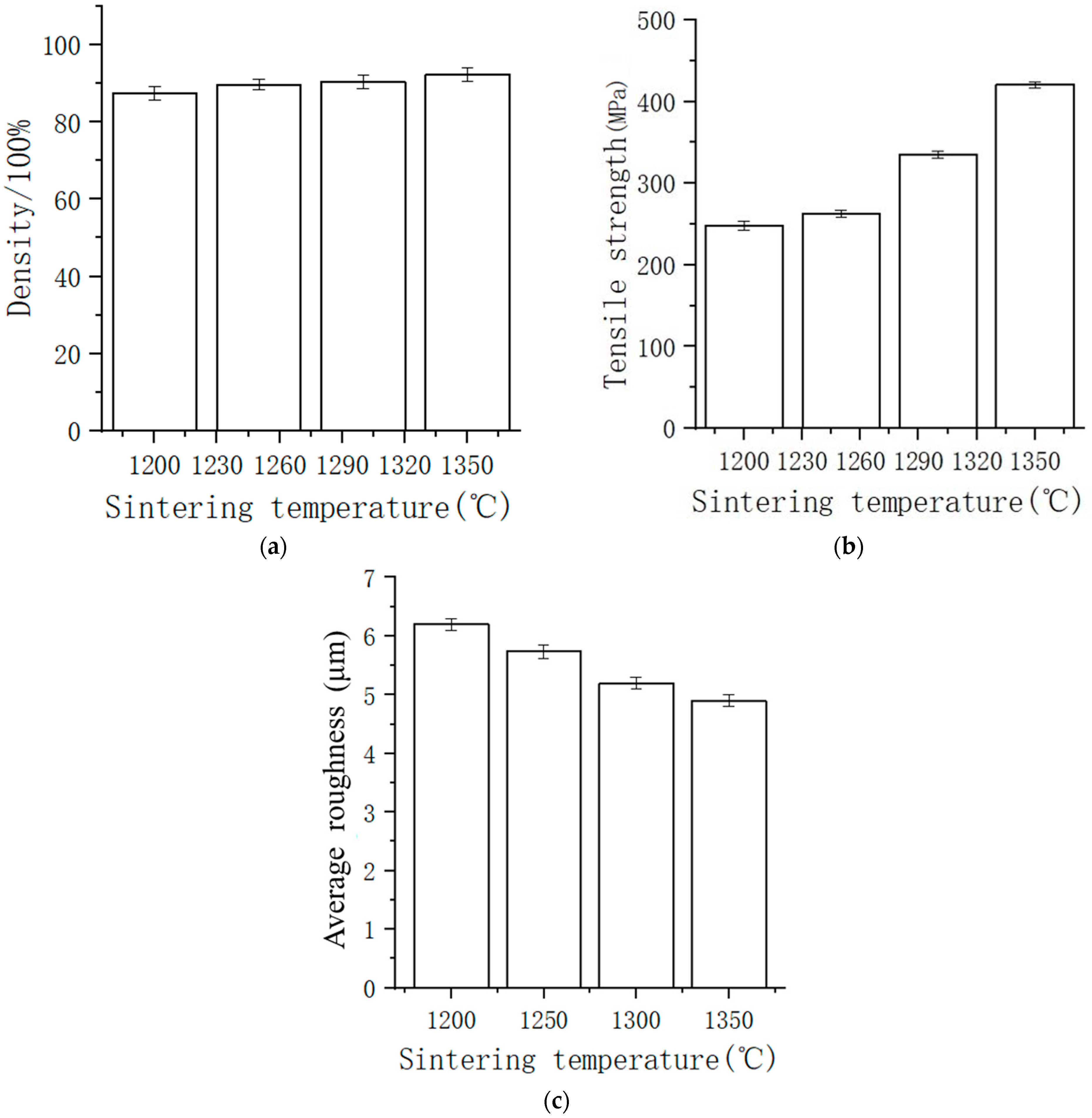
Five samples were prepared for each parameter experiment, and the final experimental results were obtained by averaging the values after excluding the maximum and minimum values of the experimental result indicators. As shown in Figure 9, the bulk density of the specimen and the tensile strength increase with the increase in sintering temperature. This is because the smaller pore size and lower porosity during tensile loading result in higher stress conditions for pore failure. The sintering temperature has a significant effect on pores, and as the sintering temperature increases, more twinning occurs in the specimen due to grain growth, leading to increased hardness and strength. Therefore, the tensile strength is more sensitive to variations in sintering temperature. In the temperature range of 1200 °C to 1350 °C, the surface roughness value of the test specimens after sintering mainly falls within the Ra3.2 μm–Ra6.3 μm range. The surface roughness gradually improves as the sintering temperature increases. This is due to the increased density of the parts as the sintering temperature rises, leading to an improvement in surface roughness. However, beyond 1350 °C, a further increase in temperature has little effect on the surface roughness.
3.4. Orthogonal Experiment
According to the orthogonal experimental design, 12 sets of experiments were conducted, with five samples being prepared for each experiment. The final experimental results were obtained by averaging the values after excluding the maximum and minimum values of the experimental result indicators. The experimental results are shown in Table 5 below.
The results of this experiment demonstrate that each experimental factor has a significant impact on the tensile performance of the fabricated parts. K1–K4 represent the summation of experimental data from levels 1 to 4, while k1–k4 correspond to their respective average values. Based on the order of significance of the effects of each experimental factor [39], as RG > RE > RA > RF > RB > RD > RC, the factors are ranked as follows: (G) sintering temperature, (E) debinding temperature, (A) nozzle temperature, (F) catalyst flow rate, (B) print bed temperature, (D) layer thickness, and (C) print speed.
4. Conclusions
This study investigates the process characteristics of fused deposition modeling (FDM) 3D printing, catalytic debinding, and high-temperature sintering for the economic and rapid manufacturing of high-melting-point metal parts using metal/polymer composite materials. The main conclusions are as follows.
(1) The FDM 3D-printed blanks are filled with metal particles, and the volume of the continuous polymer phase is relatively low, resulting in lower tensile strength compared to pure polymer specimens printed by FDM. The tensile strength of the test specimens in this printing experiment falls within the range of 3.5 to 6.5 MPa. Among the printing parameters, there is no clear regularity between the nozzle temperature and tensile strength. Increasing the printing platform temperature and filling rate can improve the tensile strength of the printed blanks. The tensile strength increases with increasing layer thickness, but as the layer thickness increases, the interlayer bonding effect deteriorates, leading to a significant decrease in tensile strength at a layer thickness of 0.3 mm compared to 0.2 mm.
(2) The channel network inside the blank can greatly accelerate the catalytic debinding reaction rate. When the filling rate is 100%, the debinding temperature is 130 °C, and the catalyst flow rate is 0.35 mL/min; the catalytic debinding rate reaches 6 mm/h, which is 1.5–3 times faster than the catalytic debinding rate of metal powder injection molding blanks. The catalytic debinding process is not simply pushed inward from the surface. The larger particle size bond channels are removed earlier than the narrow and elongated bond channels between smaller particles. When the bond channels become narrower and more elongated, the debinding process in this area becomes slower and continues to slowly remove after the debinding interface moves inward. Materials near the filament gap or layer lines have a larger contact surface area with the catalyst gas, resulting in better catalytic debinding effects.
(3) During sintering, the specimen uniformly shrinks in all directions and maintains its original shape. The higher the sintering temperature, the greater the dimensional shrinkage rate, the higher the density, and the smaller the size and density of internal pores. At a sintering temperature of 1350 °C and a holding time of 2 h, the dimensional shrinkage rate is 17.18%, the density reaches 92.7%, and the tensile strength of the metal parts reaches approximately 420.3 MPa, which is close to the tensile strength of cast 316L parts (515 MPa). However, there is a significant difference in tensile strength compared to SLM-formed 316L parts (600 MPa) [40]. Under different sintering processes, the microstructure of the metal parts is austenite plus the FeNi phase. The sintering temperature is one of the main factors affecting the structure and properties of metal parts, and it can be appropriately increased to improve the mechanical properties of the metal parts under the premise of meeting performance requirements. During sintering, the channel network inside the blank shrinks together with the blank. Some of the small-sized filament gaps are completely fused, while the larger-sized filament gaps are reduced but still retain their original shape.
(4) Based on the results of the orthogonal experimental analysis, it was determined that the factors have varying degrees of significance on the outcomes, with the sintering temperature (G) exerting the most pronounced effect, followed by the debinding temperature (E), nozzle temperature (A), catalyst flow rate (F), print bed temperature (B), layer thickness (D), and print speed (C). This order of significance provides valuable insights into the relative impact of each experimental factor on the overall process, thereby facilitating informed decision-making in the optimization of additive manufacturing parameters to achieve superior dimensional accuracy and material properties in the printed parts. The rigorous examination of these factors not only contributes to a more comprehensive understanding of the additive manufacturing process but also offers practical guidance to enhance the quality and performance of the produced components, thereby advancing the application of additive manufacturing technologies in various industrial sectors.
Author Contributions
W.W. and S.W.: conceptualization, software, and writing—original draft; S.W.: validation, writing—review and editing; S.W.: investigation and editing; H.L. and C.H.: validation. All authors have read and agreed to the published version of the manuscript.
Funding
The work was supported by the Project of Digital and Smart Agriculture Service Industrial Park in Guangdong Province (Research and Development of Smart Agricultural Machinery and Its Control Technology, No. GDSCYY2022-046/FNXM012022020-1-03) and the Guangdong Provincial Special Fund for Modern Agriculture Industry Technology Innovation Teams (Tea Industry Innovation Team Facility and Mechanization Post Expert, No. 2023KJ120). Author Weibin Wu has received research support from the Project of Digital and Smart Agriculture Service Industrial Park in Guangdong Province and the Guangdong Provincial Special Fund for Modern Agriculture Industry Technology Innovation Teams.
Data Availability Statement
Data are contained within the article.
Acknowledgments
The authors acknowledge the editors and reviewers for their constructive comments and support of this work.
Conflicts of Interest
The authors declare no conflict of interest.
References
- Herzberger, J.; Sirrine, J.M.; Williams, C.B.; Long, T.E. Polymer design for 3D printing elastomers: Recent advances in structure, properties, and printing. Prog. Polym. Sci. 2019, 97, 101144. [Google Scholar] [CrossRef]
- Pollack, S.; Venkatesh, C.; Neff, M.; Healy, A.V.; Hu, G.; Fuenmayor, E.A.; Devine, D.M. Polymer-Based additive manufacturing: Historical developments, process types and material considerations. In Polymer-Based Additive Manufacturing; Springer: Cham, Switzerland, 2019; pp. 1–22. [Google Scholar] [CrossRef]
- Shahrubudin, N.; Lee, T.C.; Ramlan, R. An overview on 3D printing technology: Technological, materials, and applications. Procedia Manuf. 2019, 35, 1286–1296. [Google Scholar] [CrossRef]
- Khairallah, S.A.; Anderson, A.T.; Rubenchik, A.; King, W.E. Laser powder-bed fusion additive manufacturing: Physics of complex melt flow and formation mechanisms of pores, spatter, and denudation zones. Acta Mater. 2016, 108, 36–45. [Google Scholar] [CrossRef]
- Frazier, W.E. Metal Additive Manufacturing: A Review. J. Mater. Eng. Perform. 2014, 23, 1917–1928. [Google Scholar] [CrossRef]
- Ravalji, J.M.; Raval, S.J. Review of quality issues and mitigation strategies for metal powder bed fusion. Rapid Prototyp. J. 2023, 29, 792–817. [Google Scholar] [CrossRef]
- Piscopo, G.; Iuliano, L. Current research and industrial application of laser powder directed energy deposition. Int. J. Adv. Manuf. Technol. 2022, 119, 6893–6917. [Google Scholar] [CrossRef]
- Gibson, I.; Rosen, D.; Stucker, B.; Khorasani, M. Powder bed fusion. In Additive Manufacturing Technologies; Springer: Cham, Switzerland, 2021; pp. 125–170. [Google Scholar]
- Ahn, D.G. Directed energy deposition (DED) process: State of the art. Int. J. Precis. Eng. Manuf.-Green Technol. 2021, 8, 703–742. [Google Scholar] [CrossRef]
- Singh, D.D.; Mahender, T.; Reddy, A.R. Powder bed fusion process: A brief review. Mater. Today Proc. 2021, 46, 350–355. [Google Scholar] [CrossRef]
- Pilipović, A. Sheet lamination. In Polymers for 3D Printing; William Andrew Publishing: Norwich, NY, USA, 2022; pp. 127–136. [Google Scholar]
- Grasso, M.; Remani, A.; Dickins, A.; Colosimo, B.M.; Leach, R.K. In-situ measurement and monitoring methods for metal powder bed fusion: An updated review. Meas. Sci. Technol. 2021, 32, 112001. [Google Scholar] [CrossRef]
- Li, Z.; Sui, S.; Ma, X.; Tan, H.; Zhong, C.; Bi, G.; Clare, A.T.; Gasser, A.; Chen, J. High deposition rate powder-and wire-based laser directed energy deposition of metallic materials: A review. Int. J. Mach. Tools Manuf. 2022, 181, 103942. [Google Scholar] [CrossRef]
- Izadi, M.; Farzaneh, A.; Mohammed, M.; Gibson, I.; Rolfe, B. A review of laser engineered net shaping (LENS) build and process parameters of metallic parts. Rapid Prototyp. J. 2020, 26, 1059–1078. [Google Scholar] [CrossRef]
- Zhong, C.; Liu, J.; Zhao, T.; Schopphoven, T.; Fu, J.; Gasser, A.; Schleifenbaum, J.H. Laser metal deposition of Ti6Al4V—A brief review. Appl. Sci. 2020, 10, 764. [Google Scholar] [CrossRef]
- Gong, X.; Anderson, T.; Chou, K. Review on powder-based electron beam additive manufacturing technology. In Proceedings of the International Symposium on Flexible Automation, St. Louis, MO, USA, 18–20 June 2012; American Society of Mechanical Engineers: New York, NY, USA, 2012; Volume 45110, pp. 507–515. [Google Scholar]
- Bankapalli, N.K.; Gupta, V.; Saxena, P.; Bajpai, A.; Lahoda, C.; Polte, J. Filament fabrication and subsequent additive manufacturing, debinding, and sintering for extrusion-based metal additive manufacturing and their applications: A review. Compos. Part B Eng. 2023, 264, 110915. [Google Scholar] [CrossRef]
- Singh, G.; Missiaen, J.M.; Bouvard, D.; Chaix, J.M. Copper extrusion 3D printing using metal injection moulding feedstock: Analysis of process parameters for green density and surface roughness optimization. Addit. Manuf. 2021, 38, 101778. [Google Scholar] [CrossRef]
- Thompson, Y.; Gonzalez-Gutierrez, J.; Kukla, C.; Felfer, P. Fused filament fabrication, debinding and sintering as a low cost additive manufacturing method of 316L stainless steel. Addit. Manuf. 2019, 30, 100861. [Google Scholar] [CrossRef]
- He, T.; Zhang, S.; Kong, X.; Wu, J.; Liu, L.L.; Wu, D.; Su, Z. Influence of diamond parameters on microstructure and properties of copper-based diamond composites manufactured by Fused Deposition Modeling and Sintering (FDMS). J. Alloys Compd. 2023, 931, 167492. [Google Scholar] [CrossRef]
- Wen, L.J.; Hu, X.G.; Li, Z.; Wang, Z.H.; Wu, J.K.; Zhu, Q. Anisotropy in tensile properties and fracture behaviour of 316L stainless steel parts manufactured by fused deposition modelling and sintering. Adv. Manuf. 2022, 10, 345–355. [Google Scholar] [CrossRef]
- Malhotra, M.K.; Grover, V. An assessment of survey research in POM: From constructs to theory. J. Oper. Manag. 1998, 16, 407–425. [Google Scholar] [CrossRef]
- Shubhra, Q.T.; Alam, A.M.; Quaiyyum, M.A. Mechanical properties of polypropylene composites: A review. J. Thermoplast. Compos. Mater. 2013, 26, 362–391. [Google Scholar] [CrossRef]
- Klingshirn, C. ZnO: Material, physics and applications. ChemPhysChem 2007, 8, 782–803. [Google Scholar] [CrossRef]
- Du, J.B.; Tang, Y.L.; Long, Z.W.; Shuang, H.H.; Tao, L. Theoretical calculation of spectra of dibutyl phthalate and dioctyl phthalate. Russ. J. Phys. Chem. A 2014, 88, 819–822. [Google Scholar] [CrossRef]
- Martin, J.H.; Yahata, B.D.; Hundley, J.M.; Mayer, J.A.; Schaedler, T.A.; Pollock, T.M. 3D printing of high-strength aluminium alloys. Nature 2017, 549, 365–369. [Google Scholar] [CrossRef] [PubMed]
- Thijs, L.; Verhaeghe, F.; Craeghs, T.; Van Humbeeck, J.; Kruth, J.P. A study of the microstructural evolution during selective laser melting of Ti–6Al–4V. Acta Mater. 2010, 58, 3303–3312. [Google Scholar] [CrossRef]
- Yu, Z.; Gao, Y.; Jiang, J.; Hai, G.; Shuaishuai, L.; Hongjun, N.; Wang, X.; Jia, C. Study on effects of FDM 3D printing parameters on mechanical properties of polylactic acid. IOP Conf. Ser. Mater. Sci. Eng. 2019, 688, 033026. [Google Scholar] [CrossRef]
- GB/T 16421-1996; Plastics–Determination of Tensile Properties by Use of Small Specimens. Industrial Standards Committee: Beijing, China, 1996.
- Hwang, K.S.; Lin, H.K.; Lee, S.C. Thermal, solvent, and vacuum debinding mechanisms of PIM compacts. Mater. Manuf. Process. 1997, 12, 593–608. [Google Scholar] [CrossRef]
- Liu, D.M.; Tseng, W.J. Influence of debinding rate, solid loading and binder formulation on the green microstructure and sintering behaviour of ceramic injection mouldings. Ceram. Int. 1998, 24, 471–481. [Google Scholar] [CrossRef]
- Enneti, R.K.; Park, S.J.; German, R.M.; Atre, S.V. Thermal debinding process in particulate materials processing. Mater. Manuf. Process. 2012, 27, 103–118. [Google Scholar] [CrossRef]
- Gierl-Mayer, C.; de Oro Calderon, R.; Danninger, H. The role of oxygen transfer in sintering of low alloy steel powder compacts: A review of the “internal getter” effect. JOM 2016, 68, 920–927. [Google Scholar] [CrossRef]
- Chasoglou, D.; Hryha, E.; Nyborg, L. Effect of process parameters on surface oxides on chromium-alloyed steel powder during sintering. Mater. Chem. Phys. 2013, 138, 405–415. [Google Scholar] [CrossRef]
- Wu, Y.; Blaine, D.; Schlaefer, C.; Marx, B.; German, R.M. Sintering densification and microstructural evolution of injection molding grade 17-4 PH stainless steel powder. Metall. Mater. Trans. A 2002, 33, 2185–2194. [Google Scholar] [CrossRef]
- Chauhan, A.; Chauhan, P. Powder XRD technique and its applications in science and technology. J. Anal. Bioanal. Tech. 2014, 5, 1–5. [Google Scholar] [CrossRef]
- Patterson, A.L. The Scherrer formula for X-ray particle size determination. Phys. Rev. 1939, 56, 978. [Google Scholar] [CrossRef]
- GB/T 228.1-2010; Metallic Materials-Tensile Testing-Part 1; Method of Test at Room Temperature. Industrial Standards Committee: Beijing, China, 2010.
- Chen, Z.; Gong, K.; Huang, C.; Hu, S.; Xu, H.; Fuenmayor, E.; Major, I. Parameter optimization for PETG/ABS bilayer tensile specimens in material extrusion 3D printing through orthogonal method. Int. J. Adv. Manuf. Technol. 2023, 127, 447–458. [Google Scholar] [CrossRef]
- Brytan, Z. Comparison of Vacuum Sintered and Selective Laser Melted Steel AISI 316L. Arch. Metall. Mater. 2017, 62, 2125–2131. [Google Scholar] [CrossRef]
Figure 1.
The full process flow of FDMS manufacturing for parts.

Figure 2.
(a) Standard test specimen; (b) printing test samples.
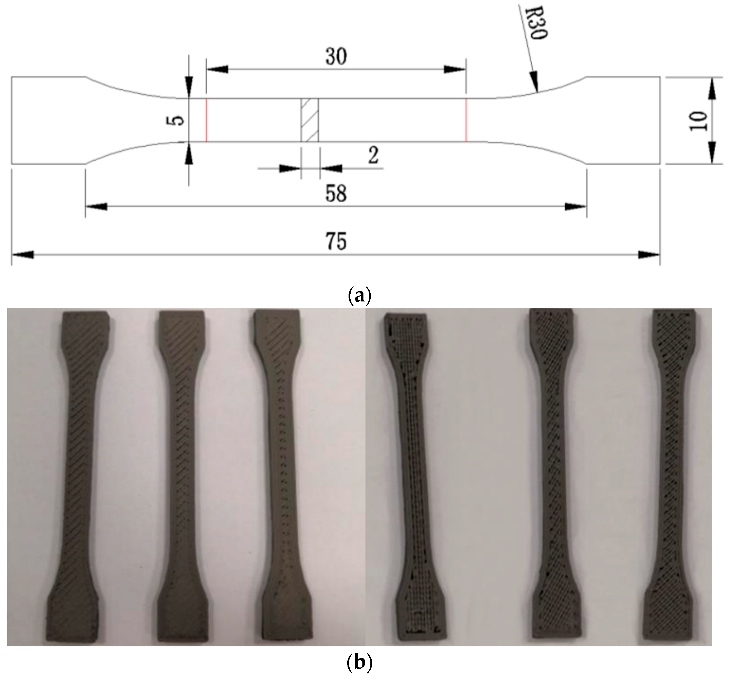
Figure 3.
Relationship between the tensile strength of the sample and the printing parameters: (a) relationship between the tensile strength and nozzle temperature; (b) relationship between the tensile strength and print bed temperature; (c) relationship between the tensile strength and layer thickness; (d) relationship between the tensile strength and filling rate.
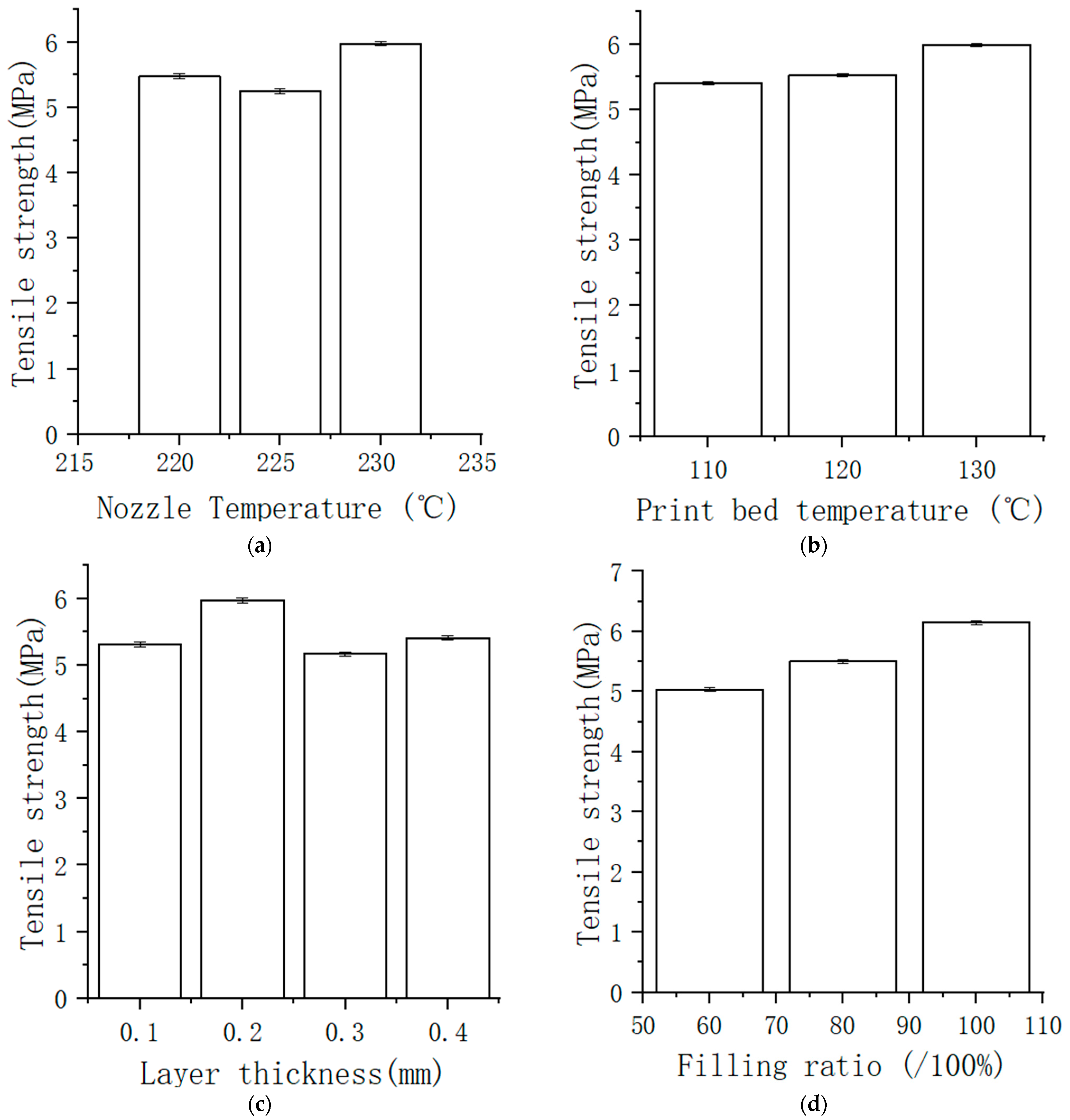
Figure 4.
DSC analysis curves before and after debinding.
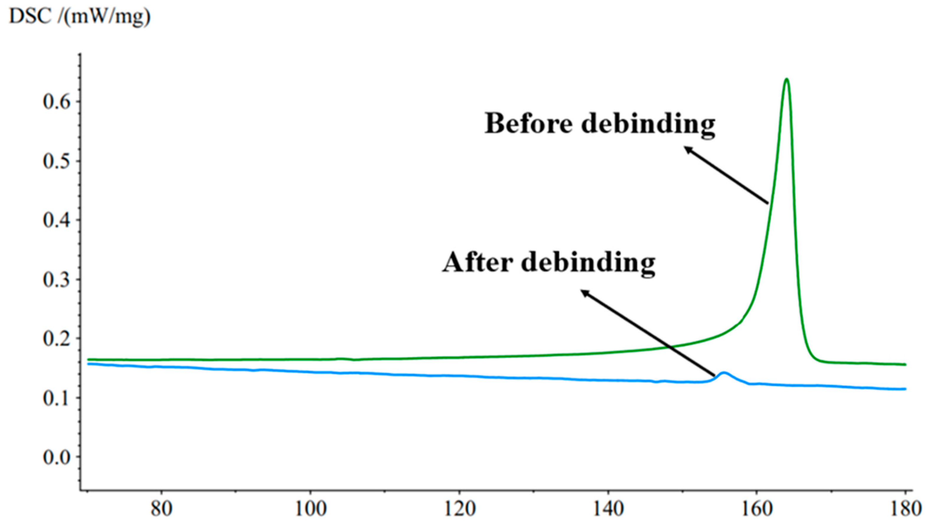
Figure 5.
SEM micrograph of debinding interface: debinding temperature 130/°C, catalyst flow rate 0.35 mL/min.
Figure 5.
SEM micrograph of debinding interface: debinding temperature 130/°C, catalyst flow rate 0.35 mL/min.
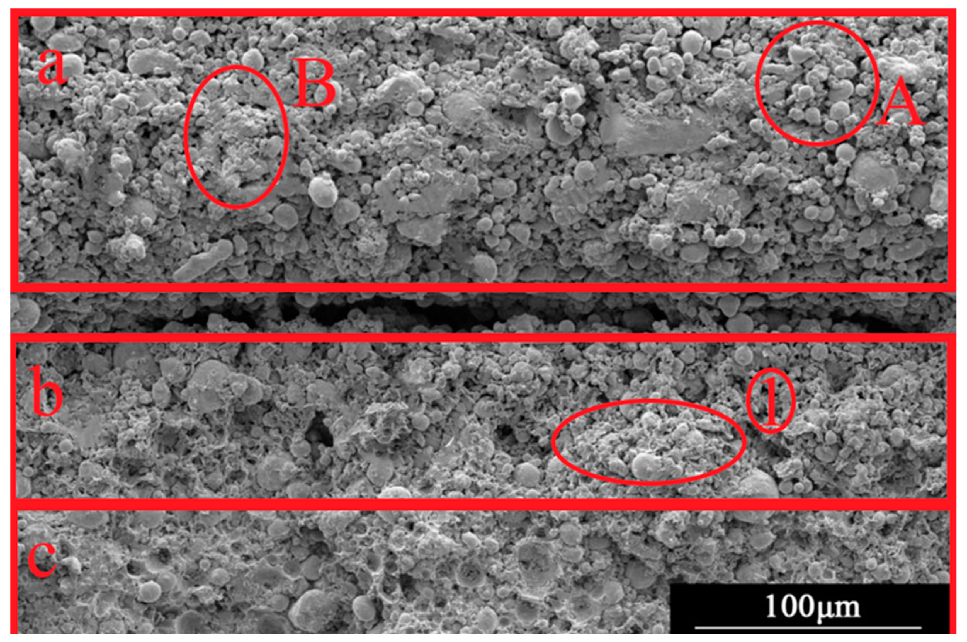
Figure 6.
Pore structure at different sintering temperatures: (a) 1200 °C; (b) 1250 °C; (c) 1300 °C; (d) 1400 °C.
Figure 6.
Pore structure at different sintering temperatures: (a) 1200 °C; (b) 1250 °C; (c) 1300 °C; (d) 1400 °C.

Figure 7.
(a) XRD phase composition at different sintering temperatures; (b) metallographic structure.
Figure 7.
(a) XRD phase composition at different sintering temperatures; (b) metallographic structure.
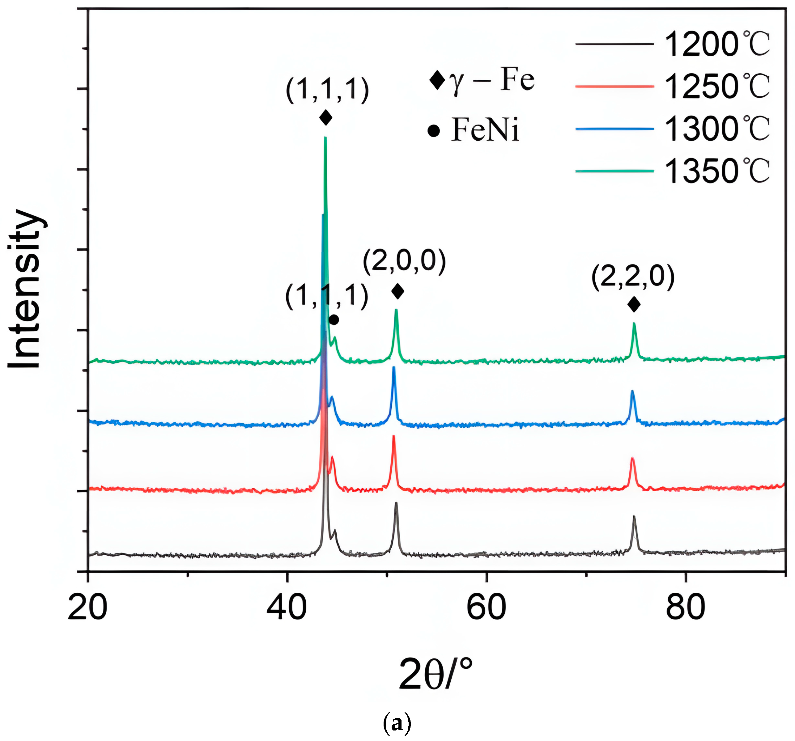

Figure 8.
(a) Standard tensile specimen; (b) sintered tensile specimen.
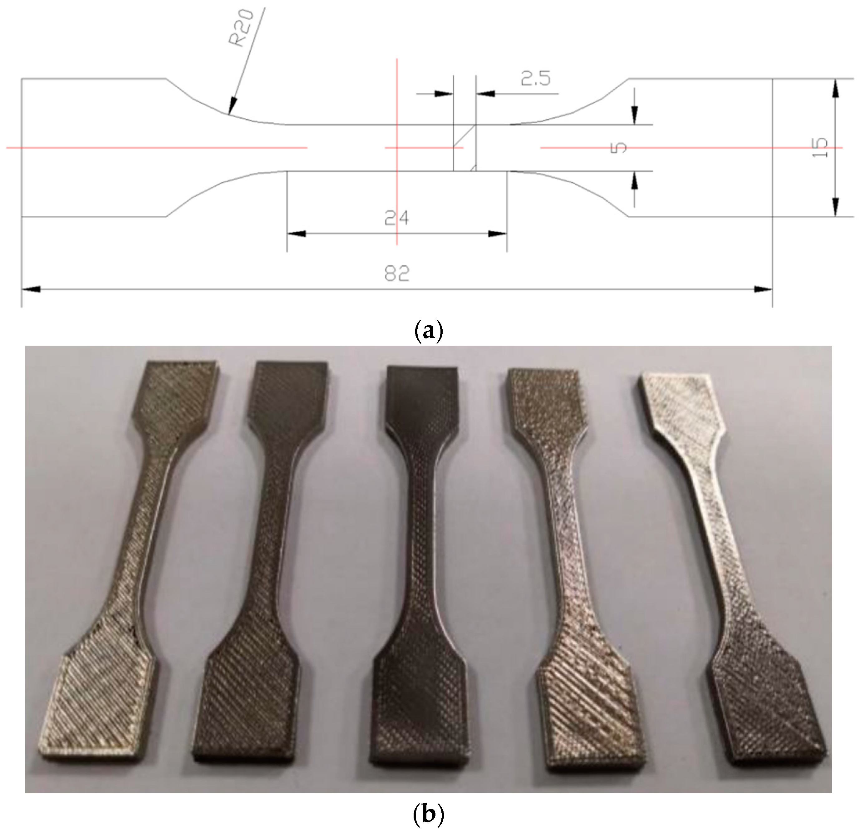
Figure 9.
Relationship between the mechanical properties of the sample and the sintering temperature. (a) Relationship between density and sintering temperature; the bulk density of metal part specimens after sintering was determined using the Archimedes displacement method. The calculation formula is as follows: ρ = m1ρ1(m1 − m2)/ρ2. In the equation, ρ represents the bulk density of the specimen (%), ρ1 represents the density of water (g/cm3), and ρ2 represents the standard density of the material being tested. For 316L stainless steel, the standard density is 7.98 g/cm3. m1 represents the weight of the specimen in air (g); m2 represents the weight of the specimen in water (g). (b) Relationship between tensile strength and sintering temperature. (c) Relationship between average roughness and sintering temperature.

Table 1.
Information of 316L stainless steel filament.
| Raw Material | Content (by Weight) |
|---|---|
| 316L stainless steel powder | 86% |
| Polyoxymethylene (POM) | 11% |
| Polypropylene (PP) | 1% |
| ZnO | 1% |
| Mixture of dioctyl phthalate (DOP) and dibutyl phthalate (DBP) | 1% |
Table 2.
Printing parameters.
| Parameters | Default Values | Alternative Values |
|---|---|---|
| Nozzle temperature/°C | 230 | 220, 225 |
| Print bed temperature/°C | 130 | 110, 120 |
| Layer thickness/mm | 0.2 | 0.1, 0.3, 0.4 |
| Filling rate/100% | 160 | 80, 100 |
Table 3.
Tensile strength test factors and levels.
| Experimental Level | A. (°C) | B. (°C) | C. (mm/s) | D. (mm) | E. (°C) | F (mL/min) | G (°C) | H (h) |
|---|---|---|---|---|---|---|---|---|
| 1 | 215 | 110 | 20 | 0.1 | 110 | 0.05 | 1200 | 2 |
| 2 | 220 | 115 | 25 | 0.2 | 120 | 0.15 | 1250 | 2 |
| 3 | 225 | 120 | 30 | 0.3 | 130 | 0.25 | 1300 | 2 |
| 4 | 230 | 125 | 35 | 0.4 | 140 | 0.35 | 1350 | 2 |
Table 4.
The volume ratio and grain size of each phase at different sintering temperatures.
| Sintering Temperature (°C) | I(111)γ/I(111)FeNi | Grain Size | |
|---|---|---|---|
| D(111)γ/nm | D(111)FeNi/nm | ||
| 1200 | 0.814/0.811 | 40.3 | 12.8 |
| 1250 | 0.801/0.196 | 42.8 | 13.3 |
| 1300 | 0.763/0.231 | 41.7 | 15.8 |
| 1350 | 0.748/0.242 | 43.9 | 16.2 |
Table 5.
Tensile test results of 316L stainless steel.
| Number | A | B | C | D | E | F | G | Tensile Strength (Mpa) |
|---|---|---|---|---|---|---|---|---|
| 1 | 1 | 1 | 1 | 1 | 1 | 2 | 1 | 247.8 |
| 2 | 1 | 2 | 2 | 2 | 2 | 3 | 2 | 264.2 |
| 3 | 1 | 3 | 4 | 3 | 3 | 1 | 3 | 334.2 |
| 4 | 2 | 4 | 3 | 4 | 4 | 4 | 4 | 412.5 |
| 5 | 2 | 2 | 3 | 1 | 4 | 1 | 3 | 330.9 |
| 6 | 2 | 1 | 2 | 3 | 3 | 2 | 4 | 416.2 |
| 7 | 3 | 3 | 1 | 4 | 2 | 3 | 2 | 272.8 |
| 8 | 3 | 4 | 4 | 2 | 1 | 4 | 1 | 256.3 |
| 9 | 3 | 1 | 2 | 3 | 4 | 3 | 2 | 270.6 |
| 10 | 4 | 4 | 1 | 2 | 3 | 4 | 4 | 420.8 |
| 11 | 4 | 3 | 4 | 1 | 2 | 2 | 3 | 340.8 |
| 12 | 4 | 2 | 3 | 4 | 1 | 1 | 1 | 250.6 |
| K1 | 864.2 | 934.6 | 941.4 | 919.5 | 754.7 | 915.7 | 754.7 | |
| K2 | 1159.6 | 845.7 | 951 | 941.3 | 877.8 | 1004.8 | 807.6 | |
| K3 | 799.7 | 947.8 | 994 | 1021 | 1171.2 | 807.6 | 1005.9 | |
| K4 | 1012.2 | 1089.6 | 931.3 | 935.9 | 1014 | 1089.6 | 1249.5 | |
| k1 | 288.1 | 311.5 | 313.8 | 306.5 | 251.6 | 305.2 | 251.6 | |
| k2 | 386.5 | 281.9 | 317 | 313.8 | 292.6 | 334.9 | 269.2 | |
| k3 | 266.6 | 315.9 | 331.3 | 340.3 | 390.4 | 269.2 | 335.3 | |
| k4 | 337.4 | 363.2 | 310.4 | 311.9 | 338 | 363.2 | 416.5 | |
| Range (R) | 119.9 | 81.3 | 20.9 | 33.8 | 138.8 | 94 | 164.9 | |
| Degree of Influence | G > E > A > F > B > D > C | |||||||
| Optimal Solution | A2B4C3D3E3F4G4 | |||||||
Disclaimer/Publisher’s Note: The statements, opinions and data contained in all publications are solely those of the individual author(s) and contributor(s) and not of MDPI and/or the editor(s). MDPI and/or the editor(s) disclaim responsibility for any injury to people or property resulting from any ideas, methods, instructions or products referred to in the content. |
© 2023 by the authors. Licensee MDPI, Basel, Switzerland. This article is an open access article distributed under the terms and conditions of the Creative Commons Attribution (CC BY) license (https://creativecommons.org/licenses/by/4.0/).
Share and Cite
MDPI and ACS Style
Wu, S.; Li, H.; Han, C.; Wu, W. Effects of Full Chain Processes on the Performance of 316L Stainless Steel Composite by Fused Deposition Modeling and Sintering. Metals 2023, 13, 2022. https://doi.org/10.3390/met13122022
AMA Style
Wu S, Li H, Han C, Wu W. Effects of Full Chain Processes on the Performance of 316L Stainless Steel Composite by Fused Deposition Modeling and Sintering. Metals. 2023; 13(12):2022. https://doi.org/10.3390/met13122022
Chicago/Turabian StyleWu, Shenglin, Haoxin Li, Chongyang Han, and Weibin Wu. 2023. "Effects of Full Chain Processes on the Performance of 316L Stainless Steel Composite by Fused Deposition Modeling and Sintering" Metals 13, no. 12: 2022. https://doi.org/10.3390/met13122022
Note that from the first issue of 2016, this journal uses article numbers instead of page numbers. See further details here.