Article

Mechanical Properties of Electrolytically Produced Copper Coatings Reinforced with Pigment Particles

by
Ivana O. Mladenović
1,
Marija M. Vuksanović
2,
Stevan P. Dimitrijević
3,
Rastko Vasilić
4,
Vesna J. Radojević
5,
Dana G. Vasiljević-Radović
1 and
Nebojša D. Nikolić
1,*
1
Institute of Chemistry, Technology and Metallurgy, University of Belgrade, Njegoševa 12, 11000 Belgrade, Serbia
2
VINČA Institute of Nuclear Sciences—National Institute of the Republic of Serbia, University of Belgrade, 11000 Belgrade, Serbia
3
Innovation Centre, Faculty of Technology and Metallurgy, University of Belgrade, Karnegijeva 4, 11000 Belgrade, Serbia
4
Faculty of Physics, University of Belgrade, Studentski Trg 12-16, 11000 Belgrade, Serbia
5
Faculty of Technology and Metallurgy, University of Belgrade, Karnegijeva 4, 11000 Belgrade, Serbia
*
Author to whom correspondence should be addressed.
Metals 2023, 13(12), 1979; https://doi.org/10.3390/met13121979
Submission received: 27 October 2023 / Revised: 18 November 2023 / Accepted: 3 December 2023 / Published: 6 December 2023
(This article belongs to the Special Issue Electrochemical Deposition and Characterization of Metallic Materials)

Abstract

:
Copper from sulfate baths without and with added inorganic pigment particles based on strontium aluminate doped with europium and dysprosium (SrAl2O4: Eu2+, Dy3+) was electrodeposited on a brass cathode by a galvanostatic regime. Morphological, structural, and roughness analysis of the pigment particles, the pure (pigment-free) Cu coating, and the Cu coatings with incorporated pigment particles were performed using SEM, XRD, and AFM techniques, respectively. Hardness and creep resistance were considered for the examination of the mechanical properties of the Cu coatings, applying Chicot–Lesage (for hardness) and Sargent–Ashby (for creep resistance) mathematical models. The wettability of the Cu coatings was examined by the static sessile drop method by a measurement of the water contact angle. The incorporation of pigment particles in the Cu deposits did not significantly affect the morphology or texture of the coatings, while the roughness of the deposits rose with the rise in pigment particle concentrations. The hardness of the Cu coatings also increased with the increasing concentration of pigments and was greater than that obtained for the pigment-free Cu coating. The presence of the pigments caused a change in the wettability of the Cu coatings from hydrophilic (for the pigment-free Cu coating) to hydrophobic (for Cu coatings with incorporated particles) surface areas.

1. Introduction

Phosphorescent particles of strontium monoaluminates, typically in the µm/nm range, are frequently applied doped powder materials in many engineering and scientific fields. These particles have a wide spectral distribution of luminescence in the visible range [1], exhibit a long afterglow at ambient temperature, and have very useful and applicable properties in the paint industry as well as in the production of functional composite coatings with a photoluminescence effect [2]. The application of afterglow phosphor particles is wide, ranging from latent fingerprint detection in forensic applications [2,3], road markings [4,5,6], light sensors [7], dye-sensitized solar cells [8], photocatalysis [9], and dosimeters [7,10].
Some of the advantages of the strontium-aluminate pigment are as follows: a high fluorescence intensity, non-radioactivity, an ability to emit yellow-green light in the dark, brightness, lifetime [11], long-afterglow luminescent features, being eco-friendly and non-toxic, and being chemically stable [1,2]. Phosphorescent or persistent luminescent strontium-aluminate pigments consist of a mineral part (SrAl2O4) and two earth elements: europium (Eu2+) and dysprosium (Dy3+) as doping ions and activators that are responsible for radiation after excitation [2,11]. The main disadvantage is the weak water resistance of this class of pigment particles and the easily breaking bond of O-Sr-O. When bonds are broken, phosphor shows a tendency to hydrolyze in water and deteriorate with the loss of luminescent intensity [11]. The main applications of the strontium-aluminate pigment are in paints, including paints used in automotive industries, luminous clocks, children’s toys, emergency signs, traffic signage, and textiles [11].
Recently, pigment particles were co-deposited with nickel through an electrochemical deposition process to obtain coatings for anticorrosion and decorative purposes [12]. This specific powder material was also used as reinforcement for copper matrix coating production in order to obtain materials for decorative and protective purposes with improved tribological properties [13,14]. However, the number of papers dealing with pigment particles as reinforcements with the aim to improve mechanical features of coatings is drastically lower than the number of papers studying the optical properties of coatings, such as phosphorescence.
The electrodeposition processes are performed in laboratory and industrial conditions and do not require a complicated and expensive system such as a vacuum. This process has simplicity, a low cost, manufacturability, and scalability when compared to other conductor or semiconductor growth processes such as MOCVD (metalloorganic chemical vapor deposition) or MBE (molecular beam epitaxy) [15]. Only the electrodeposition processes provide the conditions necessary for the controlled growth of new materials.
The co-deposition process is slightly more complex process than the usual electrodeposition because it involves an incorporation of a secondary phase into a matrix of primary material. The different materials as the second solid phase in powder, whiskers, or fiber forms can be suspended in an electroplating bath and embedded into a metal deposit during the co-deposition process. Common materials used to reinforce the copper metal matrix were metal ceramic oxides such as corundum (Al2O3) [13,14,16,17], silica (SiO2) [18,19,20], titanium oxide (TiO2) [21,22,23], CeO2 [24], zirconia (ZrO2) [25], Y2O3 [26], nitrides (Si3N4) [27,28], silicon carbide (SiC) [29,30], carbon nanotubes (CNTs) [31], multi-walled carbon nanotubes (MWCNTs) [32], graphene (Gr) and its derivatives such as graphene oxides (GO) and reduced graphene oxides (RGO) [33,34,35,36,37], diamonds [38,39], and LDH (layered double hydroxide) [40].
Copper coatings produced not only by electrodeposition processes but also by other production methods have found applications in almost all technological spheres, such as the aviation, automotive, electronics, and telecommunications industries [41]. These applications include Cu coatings obtained without and with different kinds of reinforcements [42]. Aside from traditional applications in the above-mentioned technologies, coatings of Cu were used in medicine in a control of healthcare-associated infections [43] and forensics in an analysis of latent fingerprints [44]. A modern application of electrolytically obtained Cu coatings, including those obtained with reinforcements such as Al2O3 [16] and TiO2 [21], is also related to the decrease in energy consumption in energy conversion devices. Cu coatings are used in boilers, refrigeration, air-conditioning, microelectronic cooling, nuclear reactor cooling, military equipment, mobile devices, etc. to improve boiling heat transfer mechanisms.
In this work, regarding the insufficient knowledge about the influence of pigment particles as reinforcements on the mechanical properties of Cu coatings obtained by electrodeposition, particles based on strontium aluminate doped with two rare earth metal ions (europium (Eu2+) and dysprosium (Dy3+)) were used. Copper electrodeposition was performed from a basic sulfate electrolyte to which various concentrations of the pigment particles (SrAl2O4: Eu2+, Dy3+) were added. The goal of this investigation was to examine the influence of a concentration of pigment particles on the morphological, structural, and mechanical properties of copper deposits. The produced copper matrix composite coatings are denoted as CuMC-PigP throughout this paper. The microhardness and creep resistance were examined based on mechanical properties using Vickers microindentation. The wettability properties of CuMC-PigP coatings were analyzed. A comparison with a Cu coating without added pigment particles was made.

2. Experimental

2.1. Materials and Method

Electrodeposition of copper without and with the pigment particles as reinforcements was performed in a constant galvanostatic (DC) mode via magnetic stirring (MS) of an electroplating bath (DC/MS mode) on a brass cathode (brass B36 type) in an open cell at room temperature. The basic sulfate electrolyte of Cu was 240 g L−1 CuSO4·5 H2O in 60 g L−1 H2SO4. The particles of the phosphorescent pigment were added to the sulfate bath, and four various particle concentrations were examined: 0.50, 1.00, 1.50, and 3.00 wt %. The electrolytes were made by use of doubly distilled water (Milipore, 18 MΩ·cm; Merck KGaA, Darmstadt, Germany) and p.a. reagents. The phosphorescent particles were supplied by Sennelier Paint Pigment Phosphoyellow green, Company Max Sauer SAS, Saint Brieuc, France. To ensure that particles were uniformly dispersed in the electrolyte, the electrolytes were stirred for 60 min prior to the process of co-deposition. For mixing and homogenization, a magnetic stirrer at 300 rpm was set. During the co-electrodeposition process, a magnetic stirrer at 100 rpm was set. A lower rpm during co-electrodeposition was used to avoid the appearance of vortices. The surface area of the brass cathode was 1 cm2, while the anode was copper foil situated close to the wall of the glass cell with a cylindrical shape. The current density of the electrodeposition was 50 mA·cm−2. The electrodeposition time was 750 s in all experiments.

2.2. Characterization of the Pigment Particles

The micrographs of the pigment particles with mapping and elemental analysis were obtained by the scanning electron microscope (SEM) JEOL JSM-IT 300LV (JEOL Ltd., Tokyo, Japan) model, equipped with an energy-dispersive X-ray spectroscopy (EDS) Oxford Instruments X-MANN (Oxford Instruments, Abingdon, UK) attached to it and with Aztec software (version 3.1, Springfield, NJ, USA).
The obtained SEM images were analyzed using Image-ProPlus 6.0 image analysis software (Media Cybernetics, Rockville, MD, USA) to calculate the mean diameter distribution of pigment particles and roundness. The definition of degree of sphericity, i.e., the roundness parameter, is given in [45]. If the value of this index is 1, the objects in the image are ideally spherical, while a value of 0 describes elongated objects.
A X-ray powder diffractometer (XRD, SmartLab Rigaku, Tokyo, Japan) that works on the principle of Bragg–Brentano geometry, using Cu Kα radiation of wavelength λ = 1.54178 Å, was used for a determination of the structure of the pigment particles. The voltage on the X-ray tube was 40 kV, and the current was 30 mA. Measurements were made in the range of diffraction angles 2θ from 10° to 80°, with a step of 0.02° and a measurement speed of 2°/min.

2.3. Characterization of Copper Deposits Obtained without and with Added Pigment Particles (CuMC-PigP)

The morphology of Cu coatings electrodeposited without/with the pigment particles, as well as their cross sections, was studied using SEM (models: JEOL JSM-6610LV and JEOL JSM-IT 300LV, JEOL Ltd., Tokyo, Japan). The procedure for preparing the cross section of the electrodeposited coatings is described in [46].
An atomic force microscope (AFM; model Auto Probe CP Research; TM Microscopes–Veeco Instruments, Santa Barbara, CA, USA) was used for topographical and histogramm analysis of the obtained coatings. The arithmetic average of the absolute (Ra) roughness of the coatings was determined using a combination of the software SPMLab (SPMLab NT Ver. 6.0.2., Veeco Instruments, Santa Barbara, CA, USA) and the software WSxM 4.0 Beta 9.3 Version [47].
The preferred orientation of the produced Cu and the CuMC-PigP coatings electrodeposited/co-electrodeposited on the brass cathodes was examined using a Rigaku Ultima IV diffractometer (XRD, Rigaku Co. Ltd., Tokyo, Japan) in Bragg–Brentano geometry with Cu Kα radiation in a 2θ range from 30° to 95°. The obtained XRD diffractograms were used to calculate the texture coefficients, TC(hkl), and the relative texture coefficients, RTC(hkl), of the coatings [19,48,49].
Mechanical characterization (microhardness and indentation creep) of the obtained Cu and CuMC-PigP deposits was performed using a Vickers microhardness tester known as “Leitz Kleinert Prufer DURIMET I” (Leitz, Oberkochen, Germany). To obtain the composite (or measured) hardness of pigment-free Cu and CuMC-PigP coatings, a range of applied loads (P) from 0.049 to 2.94 N and a dwell time (t) of 25 s were applied. The composite hardness of coatings was calculated using standard ASTM E384 and ISO 6507 [50]. The Chicot–Lesage (C–L) composite hardness model [51,52,53,54,55] was used to obtain the absolute hardness (Hcoat) of the Cu and CuMC-PigP deposits. Indentation creep was characterized by variations in an indentation dwell time at a constant applied indentation load of 0.98 N. The goal of this method was to analyze the validity of a power law model named Sargent–Ashby (S–A) [56,57,58,59], to determine the creep mechanism according to the calculated creep parameter and to compare the creep resistance between samples. A short-time micro creep indentation experiment was performed in order to compare the Cu and CuMC-PigP coatings and evaluate the stress exponent parameter (μ) depending on the amounts of pigment particles in the electrolyte. All micro-indentation creep tests were performed at room temperature. The dwell times were between 0 and 45 s with a step of 5 s.
The static contact angle measurements with a sessile drop of 5 μL of water (18 MΩ·cm) were performed for a determination of the wettability of the obtained electrodeposits [60,61]. For each deposit, 5 droplets at randomly chosen positions were recorded. An optical microscope equipped with a high-resolution camera (Delta Optical Smart 5.0 MP Pro, Mińsk Mazowiecki, Poland) was used for these purposes. The water drops and static contact angles (θc) were examined after taking photographs of the drops on a deposit surface (5 s after placing the drop) and determined by image analysis using Image-Pro Plus 6.0 software. The sessile drop method was performed under ambient conditions (temperature: 25 °C; relative humidity: 50%).

3. Results

3.1. Characterization of Pigment Powder Particles

The pigment powder was characterized using SEM and XRD techniques in order to obtain an insight into the composition, size, shape, and distribution of its particles.

3.1.1. Morphology of the Pigment Particles

The morphology of the pigment particles is presented in Figure 1a,b. The distribution of the average diameter and that of the roundness were obtained from the SEM images and are shown in Figure 1c,d, respectively. The pigment particles have an irregular shape and various sizes, as shown in Figure 1a,b. Analysis of the histogram of the distribution of the size of the pigment particles showed that the majority of pigment particles were smaller than 10 μm (Figure 1c). The values of the roundness parameter of 10 confirmed non-spherical and irregular particles with sharp edges.
To characterize the composition of the pigment particles, an EDS map of element distribution was produced for the surface of a larger particle (Figure 2). The elemental mapping image analysis displayed that the pigment powder was composed of O, Al, Sr, Na, Eu, and Dy (Figure 2b–g). It is clear in Figure 2 that all elements are evenly distributed on the surface of pigment particle.

3.1.2. XRD Analysis of the Pigment Particles

An XRD spectrum of the pigment powder is shown in Figure 3. All peaks were assigned by the standards No. 01-074-0794 (for SrAl2O4), 01-074-1810 (for Sr4Al4O2), and 01-080-1195 (for SrAl12O19) [62].
The presence of strontium oxide (SrO2), aluminium oxide (Al2O3), and various strontium-aluminium oxides such as SrAl2O4, Sr4Al4O2, and SrAl12O19 was identified. The peaks at 2θ angles of 25.7°, 35.2°, and 37.9° correspond to γ-Al2O3 (No. 01-073-1512). The peaks at 2θ angles of 27.0°, 28.5°, and 35.5° correspond to SrO2 (No. 00-001-1113). The typical diffraction peaks of SrAl2O4 may be seen in sharp peaks (black circle) at 20.1°, 28.5°, 29.3°, and 35.1° in the XRD pattern (No. 01-074-0794) [63]. The XRD pattern suggested that another phase of a strontium-aluminate hexagonal type (SrAl12O19) might also be detected (blue marker). The crystalline phases of doping ions (Dy3+ and Eu2+) were not detected in this analysis probably due to their low content.
Since the peaks for SrAl2O4 oxide were only dominant, a composition of the used pigment particles can be identified as SrAl2O4: Eu2+, Dy3+. Strontium-aluminate oxide (SrAl2O4) has two crystallographic polymorphs: (1) monoclinic symmetry and (2) ideal hexagonal symmetry, which makes it stable at high temperatures [11].

3.2. Characterization of Cu and CuMC-PigP Coatings

3.2.1. Morphological Analysis of the Copper Coatings–SEM Analysis

Figure 4 represents surface morphologies of the pigment-free or pure copper coating (Figure 4a) and CuMC-PigP coatings (Figure 4b–e) electrodeposited with varying amounts of pigment particles. In Figure 4f–j, the appropriate cross sections of all samples were also given.
There is no difference at the micro level between the pigment-free Cu coating and those obtained with different amounts of pigment particles (Figure 4a–e). All coatings were fine-grained and microcrystalline (mc), with a grain size smaller than 5 μm. A difference was only observed in their thicknesses, as shown in Figure 4f–j, which present cross sections of the Cu coatings obtained without/with the pigment particles. The values of the coating thickness, δ, obtained with different concentrations of pigment particles are given in Table 1. Additionally, the non-uniformity of the Cu coatings rose with the rise in the concentration of pigment particles.
Figure 5 shows the mapping analysis of pigment-free Cu (Figure 5a) and CuMC-PigP coatings obtained with minimal (0.50 wt %) (Figure 5b) and maximal amounts of pigment particles (3.00 wt %) (Figure 5c).
Aside from copper, the presence of other elements from the pigment particles was not identified on the surface area of CuMC-PigP deposits. A further mapping analysis was performed on a part of the cross section of a CuMC-PigP deposit obtained with 3.00 wt % of pigment particles (Figure 6). Element mapping performed on this cross section confirmed the presence of copper, oxygen, aluminum, strontium, europium, and dysprosium elements in the coating. This indicates that the pigment particles were embedded (incorporated) within the copper coating. The trapping mechanism of the co-deposition of small inert particles suspended in an electrolyte is usually proposed to explain their incorporation in a deposit [61]. It is clear that the increase in coating thickness with the increase in the concentration of pigment particles can be attributed to their incorporation in the coating.

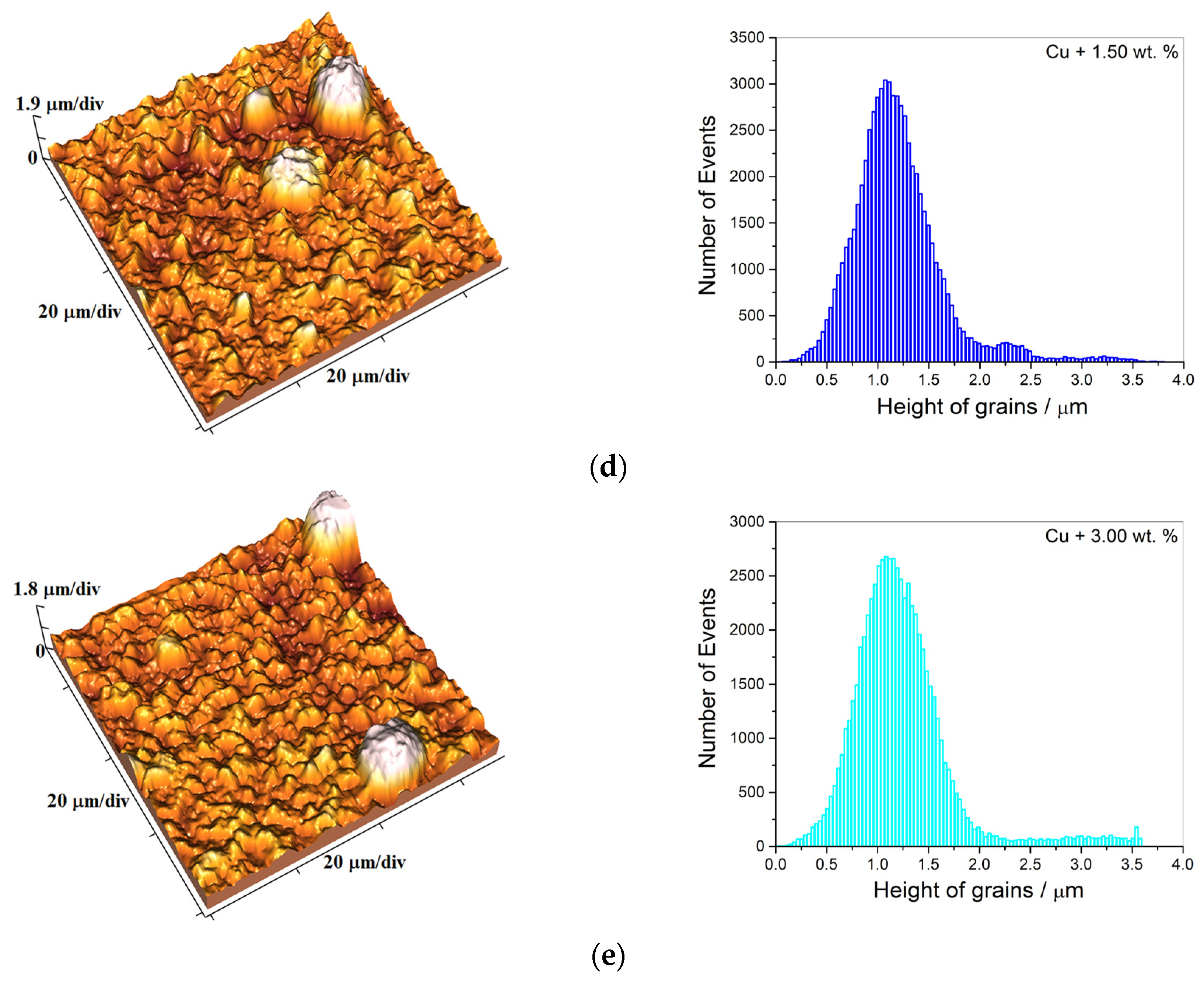
3.2.2. Topographical Analysis of the Cu Deposits—AFM Analysis

Figure 7 represents the 3D (three-dimensional) AFM topographies of the coatings and the appropriate histograms for the following coatings: the pigment-free coating (Figure 7a) and the CuMC-PigP coatings with a variation in the amount of pigment particles: 0.50 wt % (Figure 7b), 1.00 wt % (Figure 7c), 1.50 wt % (Figure 7d), and 3.00 wt % (Figure 7e). Arithmetic averages of the absolute roughness (Ra) values obtained applying AFM software (SPMLab NT Ver. 6.0.2.) for the Cu coatings produced without/with pigments are given in Table 2.
The roughness of the Cu coatings increased with the rise in the concentration of pigment particles (Table 2). This is due to the influence of the incorporation of the pigment particles in the deposit, where a higher concentration of pigment particles means a larger incorporation in the coating and hence a higher roughness of the coatings.

3.2.3. Textural Analysis of the Copper Deposits—XRD

The pigment-free Cu coating and CuMC-PigP coatings were also used for structural and textural analysis. The X-ray diffraction patterns obtained for the Cu deposits obtained from electrolytes without pigment particles and with different amounts of pigment particles are presented in Figure 8.
The diffraction peaks at 2θ angles corresponding to the crystal planes of Cu were obtained: 43.3° for (111), 50.4° for (200), 74.1° for (220), and 89.9° for (311) crystal planes, according to JCSDS standard No. 04-0836 for Cu [64]. As expected, the Cu and CuMC-PigP coatings crystallize in a face-centred cubic (FCC) crystal lattice type [26].
The dominant intensities of the diffraction peak for the (220) crystal plane was observed for all types of Cu coatings. A true estimation of the preferred orientation of the Cu electrodeposits was made by a determination of texture coefficients, TC(hkl), and the relative texture coefficients, RTC(hkl), based on the procedure described in [48,49,55,65]. The values of these coefficients of different Cu deposits are presented in Table 3.
The TC(hkl) and RTC(hkl) coefficient values for the (220) crystal plane were considerably larger than 1 and 25%, respectively, which represent the limiting values for the existence of the preferred orientation in Cu coatings [55,65,66].
Hence, the predominant (220) preferred orientation was obtained for the coating produced without pigment particles and coatings produced with various concentrations of the pigment particles. No difference in the values of these coefficients was observed for various Cu coatings. The addition of pigment particles did not manifest by the appearance of new XRD peaks, which can be explained by a concentration that is too low for XRD detection, as well as their incorporation in the interior of the coatings.

3.2.4. Mechanical Features of Cu and CuMC-PigP Coatings—The Vickers Microhardness Test

The microhardness and creep resistance were used for the examination of the mechanical properties of pure Cu and CuMC-PigP coatings obtained with different amounts of pigment particles. Vickers microindentation was applied for the analysis of these properties. The hardness of any material, and hence an electrolytically deposited coating, usually includes contributions from both the substrate (cathode) and the material (coating), and the measured hardness is denoted as the composite hardness. This variable depends on the applied load and the diagonal size of the imprint made by the used load in a coating [54,55,56,57,65,67]. One of the ways to determine the absolute hardness of a deposit is by use of composite hardness models (CHMs), whose application eliminates the contribution of the cathode to the measured (composite) hardness. For a deposit of Cu on a brass cathode, a “soft deposit on hard cathode” type of composite system, the Chicot–Lesage (C–L) CHM is recognized as an ideal mathematical model for an estimation of the absolute hardness of Cu deposits. The basis of C–L CHM is given in [52,53,54,55].

Determination of the Microhardness of Pigment-Free Cu and CuMC-PigP Coatings by Use of C–L CHM

The dependencies of the composite hardness (Hc) as well as the absolute hardness of the coatings calculated by the C–L CHM (Hcoat) on the relative indentation depth (RID) are shown in Figure 9a and Figure 9b, respectively. The RID is defined as a quotient between a depth of indentation (h) and a thickness of coating (δ), i.e., RID = h/δ [55,66,67]. An indentation depth is related to diagonal size as h = d/7 [65,66,67]. To estimate the absolute hardness of the deposits by the C–L CHM, it is necessary to know the hardness of the substrate and a parameter known as Meyer’s composite index, calculated for every coating under consideration. For the brass cathode used in this investigation, the hardness had already been calculated by the PSR (Proportional Specimen Resistance) model (1.41 GPa) [51]. By analogy with Meyer’s law [67], a modified Meyer’s index, denoted as the composite Meyer’s index (m) [68], was introduced for every coating, and calculated values are shown in Table 4.
Both the measured hardness and the calculated absolute hardness of the deposits increased with the increase in the concentration of pigment particles and were larger than those obtained for the pigment-free coating. The CuMC-PigP coating with the maximum microhardness was obtained for the maximal concentration of pigment particles (3.00 wt %), and this value is higher than that for the pure Cu coating by about 50% (46.32% for the minimal load and 49.51% for the maximal load).
Using the C–L CHM model, a critical relative indentation depth (RID)c of 0.14 has been established [51,66,68]. When (RID)c < 0.14, Hcoat > Hc, and the deposit hardness corresponds to the measured (composite) hardness. On the other hand, Hcoat < Hc when (RID)c ≥ 0.14, and the deposit hardness is equivalent to the values calculated by the C–L CHM. These values exclude the contribution of the cathode hardness to the measured hardness. This critical value has a universal character for free Cu deposits produced by various electrodeposition regimes and is independent of all electrodeposition parameters (coating thickness, the types of electrolyte stirring and the cathode, the composition of the electrolyte, i.e., the addition of levelling/brightening compounds in the electroplating bath) [65,68].
Analysis of the data shown in Figure 9a,b showed that an RID value of 0.14 as the critical value separating two areas is valid for the pigment-free Cu deposit. For easier analysis, data used for plotting graphs shown in these figures are given in the supplementary materials (Tables S1 and S2). For the Cu deposit formed with 0.50 wt % of pigment particles, Hc and Hcoat values were very close to each other when (RID)c ≥ 0.14 (for some loads, Hcoat was even higher than Hc). However, starting from c = 1.00 wt % of pigment particles, Hcoat values become larger than Hc values in the entire range of RID values. The difference between Hc and Hcoat values rose with the rise in the concentration of pigment particles. For that reason, a concentration of 1.00 wt % can be denoted as the critical value after which this type of pigment particle begins to significantly affect the Cu coating hardness. It is clear that this critical concentration led to a transformation of Cu coatings from a “soft deposit on hard cathode” type of composite system to a “hard deposit on soft cathode” type.

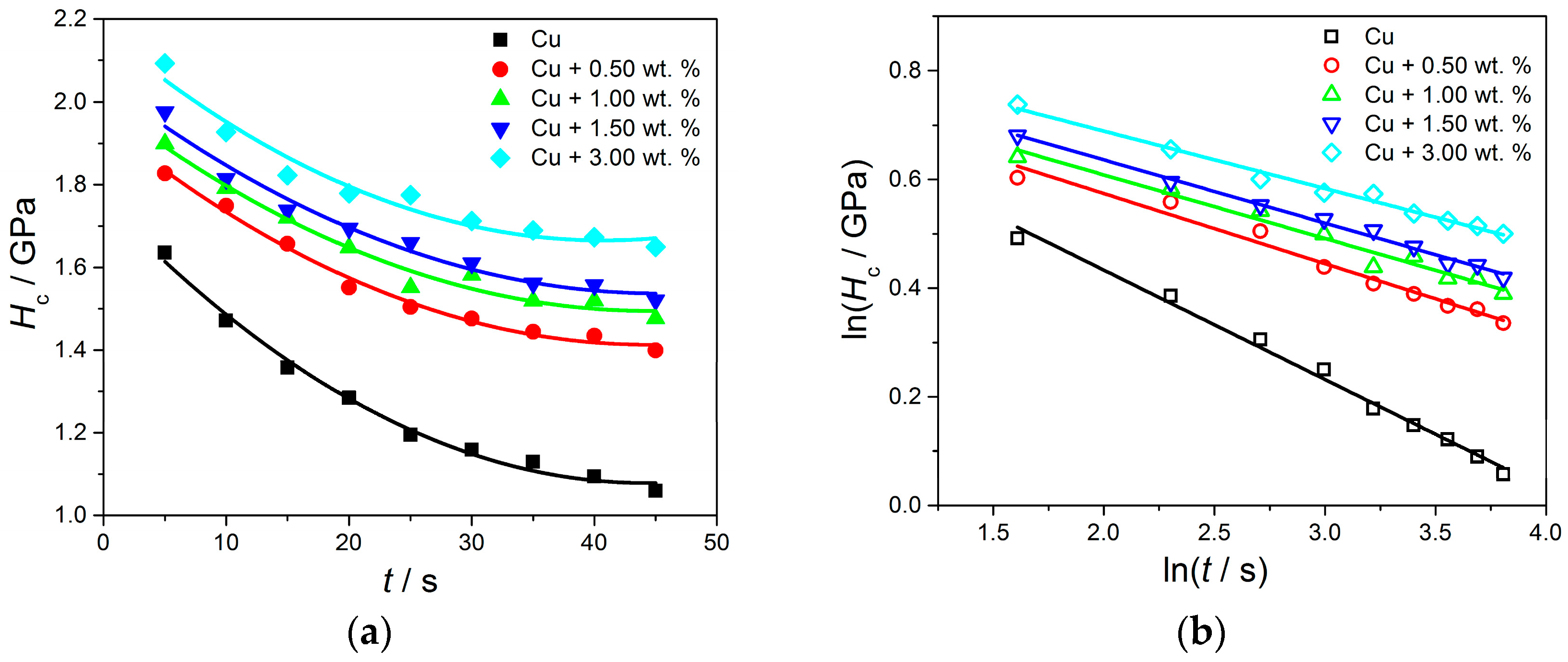
The Creep Resistance of Cu and CuMC-PigP Coatings—Indentation Creep Test

The creep response of the pigment-free Cu and CuMC-PigP coatings containing various concentrations of pigment particles was investigated with a variation in indentation dwell time (t) and by a determination of the stress exponent, μ, with the help of the Sargent–Ashby (S-A) [56,57,58,59] model.
The relationship between Hc and t enabling an analysis of creep behavior of the Cu coatings is given by Equation (1) [56,57,58,59]:
H c = σ 0 ( C · μ · ε 0 · t ) 1 μ
In Equation (1), ε0 is the strain rate at reference stress σ0, C is a constant, t is dwell time, and μ is the stress exponent.
The experimental results of creep resistance determination are given in Figure 10a,b: the dependencies of Hc on t (Figure 10a) and of ln(Hc) on ln(t) (Figure 10b). The values obtained after fitting the data in Figure 10a are listed in Table 5. The creep parameter, μ, was calculated from the linear dependence of ln(Hc) on ln(t) (Figure 10b), where the slopes of the lines correspond to a negative inverse stress exponent (−1/µ). The indentation creep features of CuMC-PigP coatings were then compared with those of free Cu coatings according to the calculated stress exponents (μ).
It is clear that composite hardness values exponentially decreased with the increasing dwell time for all Cu deposits (Figure 10a). The stress exponent values for the CuMC-PigP coatings are very close to each other and situated in the 7.73–9.41 range. They were considerably larger than the value obtained for the pigment-free Cu coating (4.96; by more than 50%). However, all values were in the range of stress exponents from 3 to 10, and this predicts that the stress mechanism comprises dislocation creep and dislocation climb [56,57,58,59]. Dislocation phenomena were relevant for all types of Cu coatings, with a clear difference among the pigment-free Cu coating and those with added pigment particles.

3.3. Wettability of Cu and CuMC-PigP Coatings

In order to examine the influence of the pigment particles on the wetting characteristics of pure copper and CuMC-PigP coatings, the sessile water-drop method, based on water contact angle measurements, θC, and image analysis was applied [69,70]. The obtained values of θC angles are shown on the histogram shown in Figure 11a, while examples of the water drops and measured contact angles for the pigment-free coating and that obtained with 3.00 wt % are shown in Figure 11b and Figure 11c, respectively.
The values of the contact angle, θC, for the CuMC-PigP coatings are very close to each other, in the range of 106.0–110.8°. The obtained contact angles were about 60% larger than the value obtained for the pure Cu coating (θC = 66.49 ± 2.75°).
As is well known, the water resistivity of coatings can be separated into two groups—clear hydrophilic (10° < θC < 90°) and clear hydrophobic (θC > 90°)—and into three secondary subtypes—super-hydrophilic (θC < 5°), super-hydrophobic (θC > 150°), and neutral (θC = 90°) coatings [71,72]. The pigment-free Cu coating can be situated in the group of the hydrophilic deposits, while those formed with the pigment particles (CuMC-PigP) belong to the group of the hydrophobic coatings.

4. Discussion

The influence of the pigment particles added as reinforcement in a Cu sulfate electrolyte on the morphology, structure and mechanical properties of copper deposits obtained by electrodeposition was investigated. Various concentrations of pigment particles based on oxides of strontium and aluminium doped with two rare earth metal ions (europium (Eu2+) and dysprosium (Dy3+)) were suspended in the electrolyte and co-deposited with Cu, forming copper matrix composite coatings (CuMC-PigP). The obtained morphological, structural, and mechanical properties were compared with those obtained for a Cu coating produced without added pigment particles (pure Cu or the pigment-free Cu coating).
The addition of the pigment particles did not have any significant influence on the morphology and texture of CuMC-PigP coatings. The pigment particles were incorporated in the electrodeposit and were not detected on the surface area of the coatings (Figure 5). The Cu deposits produced without pigment particles and with various concentrations of pigment particles were fine-grained and microcrystalline (mc) with a predominant (220) preferred orientation. As a result of the incorporation of pigment particles in the deposit, both the thickness and the roughness of the coatings increased with the rise in the concentration of pigment particles. The addition of the hard pigment particles in the electroplating bath did not affect significantly the polarization characteristics of copper (Figure S1 in the supplementary material). For this type of the particles based on aluminum oxides, mechanism of the co-deposition process and an incorporation of the hard inert particles in the electrodeposit can be considered through five consecutive steps [12,62,73]: (I) adsorption of metal ions on surface area of the particles (so-called formation of ionic clouds on particles in the bulk of electrolyte), (II) a movement of particles with adsorbed ionic clouds towards hydrodynamic boundary layer by forced convection, (III) diffusion of those particles through the diffusion double layer, (IV) adsorption of the particles with ionic clouds at the cathode surface, and (V) reduction of ionic clouds at the cathode surface after which the inert particles remain captured in the interior of growing metal deposit. In this way, it is clear why the pigment particles are not detected on the surface area of the electrodeposit.
The increase in the deposit thickness can be explained as follows: the pigment particles are based on an aluminum oxide belonging to so-called hard (metal ceramic) particles, and they are incorporated into the deposit during the electrodeposition process. Since the same amount of electricity is passed through the electrolytic cell in all cases, the amount of electrodeposited copper on the brass electrodes is the same without pigment particles and with different concentrations of the pigment particles. During the electrodeposition process, the hard pigment particles are wrapped by electrodeposited Cu, causing a greater coating thickness with a higher concentration of particles. This process also led to the rise of the non-uniformity of the deposits, as shown in Figure 4f–j. The thickness of Cu coatings increased with the inclusion of the particles in the deposit from 13.8 to 22.6 μm, i.e., by about 60%.
The roughness of Cu coatings increased with an addition of the pigment particles, reaching the increase more than 75% for the Cu coating with 3.00 wt % relative to the pigment-free coating. This strong influence of added pigment particles on the roughness of the Cu coatings makes these Cu coatings very suitable to be considered for a potential use in heat exchangers, as well as in other thermal devices [74]. For these applications, one of main challenges is an improvement of boiling heat transfer by the increase of heat transfer coefficients. One of the ways to improve the heat transfer coefficients is a modification of the surface area by the increase of its roughness. Namely, the heat transfer coefficients strongly depend on a roughness of metal surface area, with a tendency of the increase with the increase of the roughness [75]. It is clear that the co-electrodeposition process with the incorporation of the pigment particles represents a valuable way to obtain copper coatings of various degree of roughness.
The hardness of the Cu deposits also rose with the increase in the concentration of pigment particles, as shown in Figure 9a,b. The hard particles based on strontium-aluminum oxide that are incorporated in the electrodeposit cause a resistance during the indentation process, causing a smaller depth of indentation in the coating and, consequently, a smaller diagonal size of imprint on the deposit surface area. The smaller the depth of indentation, the larger the coating hardness obtained. Certainly, this increase in coating hardness is exclusively due to the incorporation of hard pigment particles. The effect of a change in coating thickness is eliminated because the increase in thickness has an effect on coating hardness opposite from that observed here. Namely, the coating hardness of Cu deposits obtained from the sulfate electrolytes on the brass cathode decreased with the rise in the deposit thickness [65]. The pigment particle concentration of 1.00 wt % represents the critical concentration after which this pigment particle type significantly affects the hardness of Cu coatings. This concentration denotes a transformation of the composite hardness system from a “soft deposit on hard cathode” type to a “hard deposit on soft cathode” type. The microhardness of the obtained Cu coatings was in line with results obtained with this type of the reinforcement [76]. For example, the microhardness of cold-sprayed Cu coatings reinforced with Al2O3 particles was in the range of 1.599–1.736 GPa, which a successful implementation of this type of the pigment particles in a production of copper matrix composite coatings additionally confirms.
The Cu deposits reinforced with the pigment particles exhibit a higher creep rate than the pure copper coating; i.e., the increase in the concentration of pigment particles favors the dislocation creep mechanism in CuMC-PigP coatings relative to the pure copper coating (Table 5). The possible reason for this is the particles acting as dislocation sources as well as the increase in the defect density in CuMC-PigP coatings compared to the pure Cu coating [77]. Generally, the reduction of the number of grain boundaries was a dominant factor for indentation creep mechanism changes. The change in the stress exponent values with the variation in the concentration of inorganic pigment particles in the bath during the co-deposition process was relatively small. The difference in creep sensitivity between the sample with 1.00 wt % of pigment particles and the sample with 3.00 wt % of pigment particles is less than 21%. A drastic change in creep sensitivity (89.6%) was noted between the pure Cu coating and the CuMC-PigP coating with the maximum particle content (3.00 wt %). The lowest creep strain was found for the CuMC-PigP deposit with 3.00 wt % of particles.
As already mentioned, the pigment-free copper coating electrodeposited on the brass substrate was hydrophilic, with a water contact angle value smaller than 90° (θC = 66.49 ± 2.75°). With an addition of pigment particles in the bath, the surface area of copper matrix composites was modified by the co-deposition of particles, and hydrophobic CuMC-PigP coatings were obtained. The measured contact angles on the surface area of CuMC-PigP deposits were in the range of 106.0–110.8° (Figure 11a). Generally, rougher coatings are more hydrophobic than the smooth coatings [71], as shown in our case. For the sake of comparison, a θC value of 63 ± 2.3° was measured for a smooth, high-energy native copper surface [71]. Hence, an increase in coating roughness leads to a change in the wettability of Cu surface area from hydrophilic to hydrophobic coatings. The change in the wettability properties of Cu deposits can be elucidated by Wenzel’s model [69,78]. The presence of larger grains, micro clusters, and protuberances on the top of the coating surface can effectively prevent the attachment of water droplets [70], which is a possible reason for the rise in the contact angle of the CuMC-PigP coatings compared to the pigment-free Cu coating. A drastic change in the contact angle of CuMC-PigP coatings was not achieved by varying the concentration of pigment particles in the bath; however, compared to the pure copper coating, the wettability was reduced by 66.6%. If it is taken into account that strontium-aluminate particles show poor water resistance [79] and reduced fluorescent brightness when more than 3% water is absorbed [80], it is not expected that there will be a significant difference in the contact angles among CuMC-PigP coatings.

5. Conclusions

In this study, copper matrix composite coatings with pigment particles based on strontium and aluminium oxides and doped with europium and dysprosium as reinforcements (CuMC-PigP) were produced via electrochemical deposition and compared with a pure, i.e., pigment-free Cu coating obtained under the same conditions. The following concentrations of pigment particles were analyzed: 0, 0.50, 1.00, 1.50, and 3.00 wt %. The following can be concluded:
The addition of the pigment particles to the electrolyte did not affect significantly the morphology or the preferred orientation of the CuMC-PigP coatings.
Due to an incorporation of pigment particles in the coatings, a rise in coating thickness was observed with the rise in the concentration of particles.
The roughness of the CuMC-PigP coatings rose with the rise in the concentration of particles.
There is a critical concentration of pigment particles (c = 1.00 wt %) after which there is a significant effect on coating hardness. Starting from this concentration, the Cu co-deposition with pigment particles led to a change in the composite hardness system from a “soft deposit on hard cathode” type to a “hard deposit on soft cathode” type.
The dominant creep mechanism in the pigment-free and CuMC-PigP coatings comprised dislocation creep and dislocation climb.
With an incorporation of pigment particles, the wettability of the Cu coatings changed from hydrophilic (for the pigment-free coating) to hydrophobic coatings obtained with various concentrations of pigment particles.

Supplementary Materials

The following supporting information can be downloaded at: https://www.mdpi.com/article/10.3390/met13121979/s1. Tables S1 and S2: The values of the composite and the calculated coating hardness by application of Chicot–Lesage composite hardness model (C–L CHM) for pure copper and various CuMC–PigP coatings; Figure S1: The cathodic polarization curves for copper electrodeposition from the electrolytes without and with added the pigment particles.

Author Contributions

Conceptualization, I.O.M. and N.D.N.; methodology, I.O.M., M.M.V. and N.D.N.; software, D.G.V.-R. and M.M.V.; validation, N.D.N., D.G.V.-R. and V.J.R.; formal analysis, S.P.D. and R.V.; investigation, I.O.M.; resources, D.G.V.-R. and N.D.N.; data curation, I.O.M., M.M.V., S.P.D. and R.V.; writing—original draft preparation, I.O.M. and N.D.N.; writing—review and editing, N.D.N., M.M.V. and I.O.M.; visualization, D.G.V.-R., M.M.V., I.O.M. and N.D.N.; supervision, N.D.N., V.J.R. and D.G.V.-R.; funding acquisition, N.D.N. All authors have read and agreed to the published version of the manuscript.

Funding

This work was financially supported by the Ministry of Science, Technological Development and Innovation of the Republic of Serbia (RS) (Grants No. 451-03-47/2023-01/200026, 451-03-47/2023-01/200017, 451-03-47/2023-01/200287, and 451-03-47/2023-01/200135).

Data Availability Statement

The data presented in this study are available from the corresponding author or co-authors upon request. The data are not publicly available due to privacy reason.

Conflicts of Interest

The authors declare no conflict of interest.

References

  1. Bite, I.; Krieke, G.; Zolotarjovs, A.; Laganovska, K.; Liepina, V.; Smits, K.; Auzins, K.; Grigorjeva, L.; Millers, D.; Skuja, L. Novel Method of Phosphorescent Strontium Aluminate Coating Preparation on Aluminum. Mater. Des. 2018, 160, 794–802. [Google Scholar] [CrossRef]
  2. Tayebi, M.; Ostad Movahed, S.; Ahmadpour, A. The Effect of the Surface Coating of a Strontium Mono-Aluminate Europium Dysprosium-Based (SrAl2O4:Eu2+,Dy3+) Phosphor by Polyethylene (PE), Polystyrene (PS) and Their Dual System on the Photoluminescence Properties of the Pigment. RSC Adv. 2019, 9, 38703–38712. [Google Scholar] [CrossRef]
  3. Sharma, V.; Das, A.; Kumar, V. Eu2+,Dy3+ Codoped SrAl2O4 Nanocrystalline Phosphor for Latent Fingerprint Detection in Forensic Applications. Mater. Res. Express 2016, 3, 015004. [Google Scholar] [CrossRef]
  4. Van der Heggen, D.; Joos, J.J.; Feng, A.; Fritz, V.; Delgado, T.; Gartmann, N.; Walfort, B.; Rytz, D.; Hagemann, H.; Poelman, D.; et al. Persistent Luminescence in Strontium Aluminate: A Roadmap to a Brighter Future. Adv. Funct. Mater. 2022, 32, 2208809. [Google Scholar] [CrossRef]
  5. Nance, J.; Sparks, T.D. Comparison of Coatings for SrAl2O4:Eu2+, Dy3+ Powder in Waterborne Road Striping Paint under Wet Conditions. Prog. Org. Coat. 2020, 144, 105637. [Google Scholar] [CrossRef]
  6. Lyu, L.; Chen, Y.; Yu, L.; Li, R.; Zhang, L.; Pei, J. The Improvement of Moisture Resistance and Organic Compatibility of SrAl2O4: Eu2+, Dy3+ Persistent Phosphors Coated with Silica–Polymer Hybrid Shell. Materials 2020, 13, 426. [Google Scholar] [CrossRef]
  7. Van der Heggen, D.; Zilenaite, R.; Ezerskyte, E.; Fritz, V.; Korthout, K.; Vandenberghe, D.; De Grave, J.; Garrevoet, J.; Vincze, L.; Poelman, D.; et al. A Standalone, Battery-Free Light Dosimeter for Ultraviolet to Infrared Light. Adv. Funct. Mater. 2022, 32, 2109635. [Google Scholar] [CrossRef]
  8. Zhang, J.; Lin, J.; Wu, J.; Zhang, S.; Zhou, P.; Chen, X.; Xu, R. Preparation of Long Persistent Phosphor SrAl2O4:Eu2+, Dy3+ and Its Application in Dye-Sensitized Solar Cells. J. Mater. Sci. Mater. Electron. 2016, 27, 1350–1356. [Google Scholar] [CrossRef]
  9. Xiao, Y.; Luo, B.; Cheng, B.; Huang, Q.; Ye, Y.; Fang, L.; Zhou, L.; Lei, S. Enhanced Visible Light Catalysis Activity of CdS-Sheathed SrAl2O4:Eu2+,Dy3+ Nanocomposites. Dalton Trans. 2018, 47, 7941–7948. [Google Scholar] [CrossRef]
  10. Arellano-Tánori, O.; Meléndrez, R.; Pedroza-Montero, M.; Castañeda, B.; Chernov, V.; Yen, W.M.; Barboza-Flores, M. Persistent Luminescence Dosimetric Properties of UV-Irradiated SrAl2O4:Eu2+, Dy3+ Phosphor. J. Lumin. 2008, 128, 173–184. [Google Scholar] [CrossRef]
  11. Rojas-Hernandez, R.E.; Rubio-Marcos, F.; Rodriguez, M.Á.; Fernandez, J.F. Long Lasting Phosphors: SrAl2O4:Eu,Dy as the Most Studied Material. Renew. Sustain. Energy Rev. 2018, 81, 2759–2770. [Google Scholar] [CrossRef]
  12. Kim, D.Y. Co-Deposition of Pigment Particles with Nickel through Electrodeposition. Ph.D. thesis, University of Toronto, Toronto, ON, Canada, 2015. [Google Scholar]
  13. Pingale, A.D.; Owhal, A.; Katarkar, A.S.; Belgamwar, S.U. Fabrication and Tribo-Mechanical Performance of Cu@Al2O3 Composite. Mater. Today Proc. 2022, 64, 1175–1181. [Google Scholar] [CrossRef]
  14. Sadoun, A.M.; Mohammed, M.M.; Fathy, A.; El-Kady, O.A. Effect of Al2O3 Addition on Hardness and Wear Behavior of Cu–Al2O3 Electro-Less Coated Ag Nanocomposite. J. Mater. Res. Technol. 2020, 9, 5024–5033. [Google Scholar] [CrossRef]
  15. Dharmadasa, I.M.; Haigh, J. Strengths and Advantages of Electrodeposition as a Semiconductor Growth Technique for Applications in Macroelectronic Devices. J. Electrochem. Soc. 2006, 153, G47. [Google Scholar] [CrossRef]
  16. Gupta, S.K.; Misra, R.D. Experimental Study of Pool Boiling Heat Transfer on Copper Surfaces with Cu-Al2O3 Nanocomposite Coatings. Int. Commun. Heat Mass Transf. 2018, 97, 47–55. [Google Scholar] [CrossRef]
  17. Hayashi, H.; Izumi, S.; Tari, I. Codeposition of α-Alumina Particles from Acid Copper Sulfate Bath. J. Electrochem. Soc. 1993, 140, 362–365. [Google Scholar] [CrossRef]
  18. Bengoa, L.N.; Ispas, A.; Bengoa, J.F.; Bund, A.; Egli, W.A. Ultrasound Assisted Electrodeposition of Cu-SiO2 Composite Coatings: Effect of Particle Surface Chemistry. J. Electrochem. Soc. 2019, 166, D244–D251. [Google Scholar] [CrossRef]
  19. Maharana, H.S.; Lakra, S.; Pal, S.; Basu, A. Electrophoretic Deposition of Cu-SiO2 Coatings by DC and Pulsed DC for Enhanced Surface-Mechanical Properties. J. Mater. Eng. Perform. 2016, 25, 327–337. [Google Scholar] [CrossRef]
  20. Zamblau, I.; Varvara, S.; Muresan, L.M. Corrosion Behavior of Cu–SiO2 Nanocomposite Coatings Obtained by Electrodeposition in the Presence of Cetyl Trimethyl Ammonium Bromide. J. Mater. Sci. 2011, 46, 6484–6490. [Google Scholar] [CrossRef]
  21. Gupta, S.K.; Misra, R.D. Effect of Two-Step Electrodeposited Cu–TiO2 Nanocomposite Coating on Pool Boiling Heat Transfer Performance. J. Therm. Anal. Calorim. 2019, 136, 1781–1793. [Google Scholar] [CrossRef]
  22. Gupta, S.K.; Misra, R.D. An Experimental Investigation on Flow Boiling Heat Transfer Enhancement Using Cu-TiO2 Nanocomposite Coating on Copper Substrate. Exp. Therm. Fluid Sci. 2018, 98, 406–419. [Google Scholar] [CrossRef]
  23. Ning, D.; Zhang, A.; Murtaza, M.; Wu, H. Effect of Surfactants on the Electrodeposition of Cu-TiO2 Composite Coatings Prepared by Jet Electrodeposition. J. Alloys Compd. 2019, 777, 1245–1250. [Google Scholar] [CrossRef]
  24. Mangam, V.; Bhattacharya, S.; Das, K.; Das, S. Friction and Wear Behavior of Cu–CeO2 Nanocomposite Coatings Synthesized by Pulsed Electrodeposition. Surf. Coat. Technol. 2010, 205, 801–805. [Google Scholar] [CrossRef]
  25. Akhtar, K.; Hira, U.; Khalid, H.; Zubair, N. Uniform Fine Particles of ZrO2 as Reinforcement Filler in the Electrodeposited Cu-ZrO2 Nanocomposite Coating on Steel Substrate. J. Alloys Compd. 2019, 772, 15–24. [Google Scholar] [CrossRef]
  26. Maharana, H.S.; Panda, S.; Basu, A. Effect of Texture and Microstructure on Properties of Electrodeposited Cu-SiO2 and Cu-Y2O3 Coatings. Surf. Coat. Technol. 2017, 315, 558–566. [Google Scholar] [CrossRef]
  27. Eslami, M.; Saghafian, H.; Golestani-fard, F.; Robin, A. Effect of Electrodeposition Conditions on the Properties of Cu–Si3N4 Composite Coatings. Appl. Surf. Sci. 2014, 300, 129–140. [Google Scholar] [CrossRef]
  28. Robin, A.; de Santana, J.C.P.; Sartori, A.F. Co-Electrodeposition and Characterization of Cu–Si3N4 Composite Coatings. Surf. Coat. Technol. 2011, 205, 4596–4601. [Google Scholar] [CrossRef]
  29. Banthia, S.; Sengupta, S.; Das, S.; Das, K. Cu, Cu-SiC Functionally Graded Coating for Protection against Corrosion and Wear. Surf. Coat. Technol. 2019, 374, 833–844. [Google Scholar] [CrossRef]
  30. Zhu, J.; Liu, L.; Zhao, H.; Shen, B.; Hu, W. Microstructure and Performance of Electroformed Cu/Nano-SiC Composite. Mater. Des. 2007, 28, 1958–1962. [Google Scholar] [CrossRef]
  31. Wang, C.; Gan, X.; Tao, J.; Xie, M.; Yi, J.; Liu, Y. Compression and Electromagnetic Shielding Properties of CNTs Reinforced Copper Foams Prepared through Electrodeposition. Vacuum 2019, 167, 159–162. [Google Scholar] [CrossRef]
  32. Bengoa, L.N.; Seré, P.R.; Pary, P.; Conconi, M.S.; Folgueiras, J.M.; Morel, E.N.; Torga, J.; Egli, W.A. Self-Lubricating Cu-MWCNT Coatings Deposited from an Ecofriendly Glutamate-Based Electrolyte. Surf. Coat. Technol. 2020, 388, 125590. [Google Scholar] [CrossRef]
  33. Wang, T.; Zhao, R.; Zhan, K.; Bao, L.; Zhang, Y.; Yang, Z.; Yan, Y.; Zhao, B.; Yang, J. Preparation of Electro-Reduced Graphene Oxide/Copper Composite Foils with Simultaneously Enhanced Thermal and Mechanical Properties by DC Electro-Deposition Method. Mater. Sci. Eng. A 2021, 805, 140574. [Google Scholar] [CrossRef]
  34. Mathew, R.T.; Singam, S.; Kollu, P.; Bohm, S.; Prasad, M.J.N.V. Achieving Exceptional Tensile Strength in Electrodeposited Copper through Grain Refinement and Reinforcement Effect by Co-Deposition of Few Layered Graphene. J. Alloys Compd. 2020, 840, 155725. [Google Scholar] [CrossRef]
  35. Joseph, A.; Kirubasankar, B.; Mathew, A.M.; Narayanasamy, M.; Yan, C.; Angaiah, S. Influence of Pulse Reverse Current Parameters on Electrodeposition of Copper-Graphene Nanocomposite Coating. Appl. Surf. Sci. Adv. 2021, 5, 100116. [Google Scholar] [CrossRef]
  36. Qu, W.; Zhang, J.; Zhang, S.; Li, N.; Liu, C.; Yu, X.; Song, Y.; Han, S.; Chen, L.; Xi, M.; et al. Copper Matrix Composites Reinforced by Three-Dimensional Netlike Graphene towards Enhanced Mechanical Property and Wear Resistance. Compos. Commun. 2022, 32, 101187. [Google Scholar] [CrossRef]
  37. Park, J.-H.; Fujita, Y.; Hagio, T.; Phouthavong, V.; Kamimoto, Y.; Bessho, T.; Ichino, R. Preliminary Study on Electrodeposition of Copper Platings and Codeposition of Carbon Nanotubes from Organic Solvent. Coatings 2023, 13, 802. [Google Scholar] [CrossRef]
  38. Hagio, T.; Park, J.-H.; Naruse, Y.; Goto, Y.; Kamimoto, Y.; Ichino, R.; Bessho, T. Electrodeposition of Nano-Diamond/Copper Composite Platings: Improved Interfacial Adhesion between Diamond and Copper via Formation of Silicon Carbide on Diamond Surface. Surf. Coat. Technol. 2020, 403, 126322. [Google Scholar] [CrossRef]
  39. Wu, Y.; Sun, Y.; Luo, J.; Cheng, P.; Wang, Y.; Wang, H.; Ding, G. Microstructure of Cu-Diamond Composites with near-Perfect Interfaces Prepared via Electroplating and Its Thermal Properties. Mater. Charact. 2019, 150, 199–206. [Google Scholar] [CrossRef]
  40. Zhang, Y.; Xu, H.; Lu, S. Preparation and Application of Layered Double Hydroxide Nanosheets. RSC Adv. 2021, 11, 24254–24281. [Google Scholar] [CrossRef]
  41. Copper Plating Service. Available online: https://www.sharrettsplating.com/coatings/copper (accessed on 9 November 2023).
  42. Singh, K.; Khanna, V.; Sonu; Singh, S.; Bansal, S.A.; Chaudhary, V.; Khosla, A. Paradigm of state-of-the-art CNT reinforced copper metal matrix composites: Processing, characterizations, and applications. J. Mater. Res. Technol. 2023, 24, 8572–8605. [Google Scholar] [CrossRef]
  43. Bharadishettar, N.; Bhat, U.K.; Panemangalore, D.B. Coating technologies for copper based antimicrobial active surfaces: A perspective review. Metals 2021, 11, 711. [Google Scholar] [CrossRef]
  44. Yao, K.-M.; Xu, M.; Huang, X.-Z.; Mo, D.-C.; Lyu, S.-S. Electrochemical deposition of copper films to develop the latent sebaceous fingerprints on metal substrates. J. Electroanal. Chem. 2023, 941, 117526. [Google Scholar] [CrossRef]
  45. Cruz-Matías, I.; Ayala, D.; Hiller, D.; Gutsch, S.; Zacharias, M.; Estradé, S.; Peiró, F. Sphericity and Roundness Computation for Particles Using the Extreme Vertices Model. J. Comput. Sci. 2019, 30, 28–40. [Google Scholar] [CrossRef]
  46. Mladenović, I.; Jakšić, Z.; Obradov, M.; Vuković, S.; Isić, G.; Tanasković, D.; Lamovec, J. Subwavelength Nickel-Copper Multilayers as an Alternative Plasmonic Material. Opt. Quantum Electron. 2018, 50, 203. [Google Scholar] [CrossRef]
  47. Horcas, I.; Fernández, R.; Gómez-Rodríguez, J.M.; Colchero, J.; Gómez-Herrero, J.; Baro, A.M. WSXM: A Software for Scanning Probe Microscopy and a Tool for Nanotechnology. Rev. Sci. Instrum. 2007, 78, 013705. [Google Scholar] [CrossRef] [PubMed]
  48. Nikolić, N.D.; Maksimović, V.M.; Avramović, L. Correlation of Morphology and Crystal Structure of Metal Powders Produced by Electrolysis Processes. Metals 2021, 11, 859. [Google Scholar] [CrossRef]
  49. Bérubé, L.P.; L’Espérance, G. A Quantitative Method of Determining the Degree of Texture of Zinc Electrodeposits. J. Electrochem. Soc. 1989, 136, 2314–2315. [Google Scholar] [CrossRef]
  50. Broitman, E. Indentation Hardness Measurements at Macro-, Micro-, and Nanoscale: A Critical Overview. Tribol. Lett. 2017, 65, 23. [Google Scholar] [CrossRef]
  51. Mladenović, I.O.; Nikolić, N.D.; Lamovec, J.S.; Vasiljević-Radović, D.; Radojević, V. Application of the Composite Hardness Models in the Analysis of Mechanical Characteristics of Electrolytically Deposited Copper Coatings: The Effect of the Type of Substrate. Metals 2021, 11, 111. [Google Scholar] [CrossRef]
  52. Chicot, D.; Lesage, J. Absolute Hardness of Films and Coatings. Thin Solid Film. 1995, 254, 123–130. [Google Scholar] [CrossRef]
  53. Lesage, J.; Chicot, D.; Pertuz, A.; Jouan, P.-Y.; Horny, N.; Soom, A. A Model for Hardness Determination of Thin Coatings from Standard Micro-Indentation Tests. Surf. Coat. Technol. 2005, 200, 886–889. [Google Scholar] [CrossRef]
  54. Lesage, J.; Pertuz, A.; Puchi-Cabrera, E.S.; Chicot, D. A Model to Determine the Surface Hardness of Thin Films from Standard Micro-Indentation Tests. Thin Solid Film. 2006, 497, 232–238. [Google Scholar] [CrossRef]
  55. Mladenović, I.O.; Lamovec, J.S.; Vasiljević Radović, D.G.; Vasilić, R.; Radojević, V.J.; Nikolić, N.D. Morphology, Structure and Mechanical Properties of Copper Coatings Electrodeposited by Pulsating Current (PC) Regime on Si(111). Metals 2020, 10, 488. [Google Scholar] [CrossRef]
  56. Mladenović, I.O.; Lamovec, J.S.; Vasiljević-Radović, D.G.; Radojević, V.J.; Nikolić, N.D. Mechanical features of copper coatings electrodeposited by the pulsating current (PC) regime on Si(111) substrate. Int. J. Electrochem. Sci. 2020, 15, 12173–12191. [Google Scholar] [CrossRef]
  57. Sargent, P.M.; Ashby, M.F. Indentation Creep. Mater. Sci. Technol. 1992, 8, 594–601. [Google Scholar] [CrossRef]
  58. Farhat, S.; Rekaby, M.; Awad, R. Vickers Microhardness and Indentation Creep Studies for Erbium-Doped ZnO Nanoparticles. SN Appl. Sci. 2019, 1, 546. [Google Scholar] [CrossRef]
  59. Vuksanovic, M.; Mladenovic, I.; Tomic, N.; Petrovic, M.; Radojevic, V.; Marinkovic, A.; Jancic-Heinemann, R. Mechanical Properties of Biomass-Derived Silica Nanoparticles Reinforced PMMA Composite Material. Sci. Sinter. 2022, 54, 211–221. [Google Scholar] [CrossRef]
  60. Parau, A.C.; Juravlea, G.A.; Raczkowska, J.; Vitelaru, C.; Dinu, M.; Awsiuk, K.; Vranceanu, D.M.; Ungureanu, E.; Cotrut, C.M.; Vladescu, A. Comparison of 316L and Ti6Al4V Biomaterial Coated by ZrCu-Based Thin Films Metallic Glasses: Structure, Morphology, Wettability, Protein Adsorption, Corrosion Resistance, Biomineralization. Appl. Surf. Sci. 2023, 612, 155800. [Google Scholar] [CrossRef]
  61. Drelich, J.; Chibowski, E.; Meng, D.D.; Terpilowski, K. Hydrophilic and Superhydrophilic Surfaces and Materials. Soft Matter 2011, 7, 9804. [Google Scholar] [CrossRef]
  62. Low, C.T.J.; Wills, R.G.A.; Walsh, F.C. Electrodeposition of Composite Coatings Containing Nanoparticles in a Metal Deposit. Surf. Coat. Technol. 2006, 201, 371–383. [Google Scholar] [CrossRef]
  63. Zhu, Y.; Pang, Z.; Wang, J.; Ge, M.; Ju, A. Research on the Afterglow Properties of Red-Emitting Phosphor: SrAl2O4:Eu2+, Dy3+/Light Conversion Agent for Red Luminous Fiber. J. Mater. Sci. Mater. Electron. 2016, 27, 7554–7559. [Google Scholar] [CrossRef]
  64. Avramović, L.; Maksimović, V.M.; Baščarević, Z.; Ignjatović, N.; Bugarin, M.; Marković, R.; Nikolić, N.D. Influence of the Shape of Copper Powder Particles on the Crystal Structure and Some Decisive Characteristics of the Metal Powders. Metals 2019, 9, 56. [Google Scholar] [CrossRef]
  65. Mladenović, I.O.; Lamovec, J.S.; Vasiljević-Radović, D.G.; Vasilić, R.; Radojević, V.J.; Nikolić, N.D. Implementation of the Chicot–Lesage Composite Hardness Model in a Determination of Absolute Hardness of Copper Coatings Obtained by the Electrodeposition Processes. Metals 2021, 11, 1807. [Google Scholar] [CrossRef]
  66. Mladenović, I.O.; Nikolić, N.D. Influence of Parameters and Regimes of the Electrodeposition on Hardness of Copper Coatings. Metals 2023, 13, 683. [Google Scholar] [CrossRef]
  67. Lamovec, J.; Jović, V.; Randjelović, D.; Aleksić, R.; Radojević, V. Analysis of the Composite and Film Hardness of Electrodeposited Nickel Coatings on Different Substrates. Thin Solid Film. 2008, 516, 8646–8654. [Google Scholar] [CrossRef]
  68. Mladenovic, I.; Lamovec, J.; Vasiljevic-Radovic, D.; Radojevic, V.; Nikolic, N. Determination of the Absolute Hardness of Electrolytically Produced Copper Coatings by Application of the Chicot-Lesage Composite Hardness Model. J. Serb. Chem. Soc. 2022, 87, 899–910. [Google Scholar] [CrossRef]
  69. Marmur, A. Hydro- Hygro- Oleo- Omni-Phobic? Terminology of Wettability Classification. Soft Matter 2012, 8, 6867. [Google Scholar] [CrossRef]
  70. Feng, L.; Li, S.; Li, Y.; Li, H.; Zhang, L.; Zhai, J.; Song, Y.; Liu, B.; Jiang, L.; Zhu, D. Super-Hydrophobic Surfaces: From Natural to Artificial. Adv. Mater. 2002, 14, 1857–1860. [Google Scholar] [CrossRef]
  71. Wang, S.; Feng, L.; Liu, H.; Sun, T.; Zhang, X.; Jiang, L.; Zhu, D. Manipulation of Surface Wettability between Superhydrophobicity and Superhydrophilicity on Copper Films. Chem. Phys. Chem. 2005, 6, 1475–1478. [Google Scholar] [CrossRef]
  72. Zhang, B.; Xu, W. Superhydrophobic, Superamphiphobic and SLIPS Materials as Anti-Corrosion and Anti-Biofouling Barriers. New J. Chem. 2021, 45, 15170–15179. [Google Scholar] [CrossRef]
  73. Celis, J.P.; Roos, J.R.; Buelens, C. A Mathematical Model for the Electrolytic Codeposition of Particles with a Metallic Matrix. J. Electrochem. Soc. 1987, 134, 1402–1408. [Google Scholar] [CrossRef]
  74. Gupta, S.K.; Misra, R.D. Experimental Pool Boiling Heat Transfer Analysis with Copper–Alumina Micro/Nanostructured Surfaces Developed by a Novel Electrochemical Deposition Technique. Int. J. Thermophys. 2023, 44, 112. [Google Scholar] [CrossRef]
  75. Jones, B.J.; McHale, J.P.; Garimella, S.V. The Influence of Surface Roughness on Nucleate Pool Boiling Heat Transfer. J. Heat Transfer. 2009, 131, 121009. [Google Scholar] [CrossRef]
  76. Triantou, K.I.; Pantelis, D.I.; Guipont, V.; Jeandin, M. Microstructure and tribological behavior of copper and composite copper+alumina cold sprayed coatings for various alumina contents. Wear 2015, 336–337, 96–107. [Google Scholar] [CrossRef]
  77. Requena, G.C.; Degischer, H.P. Effects of Particle Reinforcement on Creep Behaviour of AlSi1MgCu. Int. J. Mater. Res. 2022, 96, 807–813. [Google Scholar] [CrossRef]
  78. Wenzel, R.N. Resistance of Solid Surfaces to Wetting by Water. Ind. Eng. Chem. 1936, 28, 988–994. [Google Scholar] [CrossRef]
  79. Huang, Z.; Chen, B.; Ren, B.; Tu, D.; Wang, Z.; Wang, C.; Zheng, Y.; Li, X.; Wang, D.; Ren, Z.; et al. Smart Mechanoluminescent Phosphors: A Review of Strontium-Aluminate-Based Materials, Properties, and Their Advanced Application Technologies. Adv. Sci. 2023, 10, 2204925. [Google Scholar] [CrossRef]
  80. Nemani, S.K.; Annavarapu, R.K.; Mohammadian, B.; Raiyan, A.; Heil, J.; Haque, M.A.; Abdelaal, A.; Sojoudi, H. Surface Modification of Polymers: Methods and Applications. Adv. Mater. Interfaces 2018, 5, 1801247. [Google Scholar] [CrossRef]
Figure 1. SEM images and analysis of pigment particles obtained on different magnifications: (a) ×200, (b) ×500, (c) appropriate distribution of the mean diameter of particles, and (d) the roundness of particles.
Metals 13 01979 g001
Figure 2. (a) SEM image of the appearance and (bg) elemental mapping images of a pigment particle.
Metals 13 01979 g002
Figure 3. The X-ray diffractogram of the pigment powder.
Metals 13 01979 g003
Figure 4. Surface morphologies and cross-section analyses of electrodeposited pigment-free Cu and CuMC-PigP coatings prepared on a brass substrate with different wt % values of the pigment particles: (a,f) pigment-free Cu; (b,g) CuMC-PigP with 0.50 wt %; (c,h) CuMC-PigP with 1.00 wt %; (d,i) CuMC-PigP with 1.50 wt %; (e,j) CuMC-PigP with 3.00 wt %. Magnifications: (ae) ×1500; (fj) ×1000. The current density of the electrodeposition: 50 mA·cm−2.
Metals 13 01979 g004
Figure 5. Element mapping of the copper coatings: (a) pigment-free Cu coating and CuMC-PigP coatings with (b) 0.50 wt % and (c) 3.00 wt % of pigment particles.
Metals 13 01979 g005
Figure 6. Elemental mapping analysis performed on the cross section of the CuMC-PigP coating produced with 3.00 wt % of pigment particles.
Metals 13 01979 g006
Figure 7. The 3D (three-dimensional) AFM images and the corresponding histograms of the pigment-free Cu and CuMC-PigP coatings obtained with different amounts of the pigment particles: (a) pigment-free Cu coating and CuMC-PigP coatings with (b) 0.50 wt %, (c) 1.00 wt %, (d) 1.50 wt %, and (e) 3.00 wt % of pigment particles. The current density of the electrodeposition: j = 50 mA cm−2. AFM surface scan size was (70 × 70) μm2.
Metals 13 01979 g007aMetals 13 01979 g007b
Figure 8. The XRD diffractograms for the pure Cu coating and the CuMC-PigP coatings electrodeposited with the different amounts of pigment particles.
Metals 13 01979 g008
Figure 9. The dependencies of (a) Hc and (b) Hcoat on RID for the pure Cu and CuMC-PigP deposits obtained with different amounts of pigment particles.
Metals 13 01979 g009
Figure 10. The dependencies of (a) the composite hardness, Hc, on indentation dwell time, t, and (b) ln(Hc) on ln(t), calculated according to the Sargent–Ashby (S-A) model.
Metals 13 01979 g010
Figure 11. (a) Histogram of water contact angles measured on pure Cu and CuMC-PigP coatings electrodeposited with different wt % values of pigment particles, and images of water droplets on the coating surfaces: (b) the pigment-free coating and (c) the CuMC-PigP coating with 3.00 wt % of pigment particles.
Metals 13 01979 g011
Table 1. The values of thickness (δ) of the pigment-free Cu coating and the coatings of Cu obtained with various concentrations of the pigment particles (c, in wt %).
c/wt %00.501.001.503.00
δ/μm13.8 ± 0.1117.0 ± 0.4121.4 ± 0.6722.5 ± 1.1122.6 ± 2.17
Table 2. Arithmetic averages of the absolute roughness (Ra) values obtained applying AFM software (SPMLab NT Ver. 6.0.2.) from a 70 × 70 µm2 scan area for the Cu coatings obtained without/with pigment particles.
c/wt %00.501.001.503.00
Ra/nm197.1239.9252.4313.5349.7
Table 3. The values of TC(hkl) and RTC(hkl) coefficients calculated for the pigment-free Cu and the CuMC-PigP electrodeposits obtained with different concentrations of pigment particles.
TC(hkl)RTC(hkl)/%
c/wtTC(111)TC(200)TC(220)TC(311)RTC(111)RTC(200)RTC(220)RTC(311)
00.290.336.10.963.84.379.412.5
0.500.240.316.50.863.03.982.210.9
1.000.290.326.11.003.84.179.113.0
1.500.270.336.30.863.54.381.211.0
3.000.210.346.60.782.64.383.29.90
Table 4. The Meyer’s composite index m values for the Cu and CuMC-PigP deposits.
c/wt %00.501.001.503.00
m0.42210.43230.43140.43510.4439
Table 5. Fitting results and stress exponents for the pigment-free Cu coating and those produced with different concentrations of the pigment particles.
c/wt %Slope (k) Intercept (n) Stress Exponent (µ)R2
0−0.2015 ± 0.006940.8363 ± 0.021564.960.99
0.50−0.1171 ± 0.007640.8429 ± 0.023738.540.97
1.00−0.1293 ± 0.007750.8329 ± 0.024087.730.98
1.50−0.1164 ± 0.003670.8692 ± 0.011418.590.99
3.00−0.1063 ± 0.004270.9022 ± 0.013259.410.98
c—weight concentrations (wt %) of pigment particles added in the basic sulfate electrolyte; k—slope of the linear curves from Figure 10b; n—the values of intercept in Figure 10b; µ—calculated stress exponents and appropriate standard errors; R2—regression coefficient for the Cu and CuMC-PigP coatings with various amounts of pigment particles.
Disclaimer/Publisher’s Note: The statements, opinions and data contained in all publications are solely those of the individual author(s) and contributor(s) and not of MDPI and/or the editor(s). MDPI and/or the editor(s) disclaim responsibility for any injury to people or property resulting from any ideas, methods, instructions or products referred to in the content.

