
Studies of the Solid Particle Erosion Resistance of 30 L Steel with Different Types of Surface Modification

Laboratory of Functional Coatings in Power Engineering, Federal State Budget Educational Institution of Higher Education, MIREA—Russian Technological University, 78, Vernadskogo Ave., 119454 Moscow, Russia
*
Author to whom correspondence should be addressed.
Metals 2023, 13(12), 1978; https://doi.org/10.3390/met13121978
Submission received: 12 October 2023
/
Revised: 27 November 2023
/
Accepted: 1 December 2023
/
Published: 5 December 2023
Abstract
:Earlier studies have shown that 30 L steel, used for the manufacture of hydraulic machinery equipment elements, has greater resistance to cavitation wear than 20 GL steel. This paper presents the results of experimental studies of the solid particle erosion resistance of 30 L structural steel samples with different surface modifications based on nitriding and boriding processes. The characteristics of the modified near-surface layers were determined. The results of the solid particle erosion resistance tests carried out according to the ASTM G76-13 standard are presented. The research results demonstrated that boriding processes worsen the solid particle erosion resistance of 30 L steel at flow impact angles of 30° and 90°. All the considered variants of surface nitriding at an impact angle of 90° do not worsen the solid particle erosion resistance of 30 L steel samples, while at an impact angle of 30°, they increase the solid particle erosion resistance by at least 10–20%.
1. Introduction
The wear of the functional surfaces of paddle hydraulic machines (pumps and hydraulic turbines) can be caused by a large number of damaging factors, which, in addition to cavitation destruction, include [1,2,3,4,5,6] cavitation–waterjet, waterjet, corrosion, abrasion, and contact, as well as wear (destruction) from collision with foreign objects. When describing the wear of real hydraulic machines, it is impossible to separate one factor from another and it requires identifying the contribution of each of the factors to the overall wear process. The change in the relief of the surfaces and subsequently the shape of the flow part due to wear causes further destruction of the parts or the entire unit.
Solid particle erosion is one of the main factors affecting the reliability and availability of the whole set of hydraulic turbine design elements. The flow part of the hydraulic turbine is subjected to this type of wear, i.e., to a greater extent the runner, guide vanes, front sides of the head, and the bottom covers [7,8,9,10,11,12,13,14,15,16,17,18]. The development of waterjet wear depends on the concentration, density, geometric shape, and size of the solid particles, as well as on the mechanical properties of the material of the parts and the rotational speed of the rotor of the hydraulic machine [19,20].
At present, during the repair of hydro-turbine equipment, damage to the elements of the flow part is eliminated. During overhaul, worn parts are dismantled and remanufactured parts are installed. Worn parts are remanufactured in the inter-overhaul period using the cavern welding technique, with the replacement of covers with subsequent machining, using special tooling and fixtures.
The current methods of repair of the main elements of hydraulic turbines are outdated and have certain disadvantages. These disadvantages are long terms, high cost and, in addition, a decrease in the runner reliability due to metal structure disturbances [21,22] (the reconditioned part does not have the same parameters as the original metal), internal stresses, and mechanical and hydraulic imbalance.
Restoring the operating geometry of the runner and guide vanes remains a challenge year after year, while costs are increasing financially, materially, and over time. Because of this, additional capital investments and energy losses due to the reduced efficiency of equipment and the downtime associated with repair, and often with the dismantling of individual parts, are very high. As a consequence, the development of repair techniques using modern restoration technologies, and with the use of various methods of increasing the reliability and durability of hydraulic machine parts by modifying their surface, is becoming more and more relevant.
The selection of materials, coatings, and methods for the modification of working surfaces for machine parts operating under solid particle erosion conditions is always a topical issue. At present, protective coatings for parts of the flow part of hydraulic turbines have become the main means in the fight against waterjet and cavitation wear [23,24,25,26,27,28,29,30,31,32,33,34,35,36,37,38,39,40,41,42,43,44,45,46,47] of equipment surfaces. The coating methods used include gas–thermal and plasma spraying, physical and chemical vapor deposition, and electroplating [48,49,50,51,52,53,54,55,56,57,58].
In recent years, polymer materials have gained a dominant position for the repair of hull parts in various industries, including hydropower equipment [59,60,61]. They are various adhesive compounds based on epoxy resins, polyesters, polyurethanes, polyacrylates, and other materials with a filler of metal or ceramic powder and reinforcing fibers. These materials have good adhesive properties, which, combined with their sufficiently high strength and the ability to move from a plastic state to a solid state in a short period of time without shrinkage, provide a wide range of applications in solving repair problems. It should be noted that some polyurethane composite materials, which have shown high wear resistance during bench tests, cannot compete with hard coatings in full-scale conditions due to low adhesion to the base metal. Therefore, when choosing the protection of the parts of the flow part of the hydraulic turbines from waterjet impact, the adhesion strength of the coating with metal is one of the main characteristics of the coating.
One of the most studied coating methods in the literature is high-speed flame spraying (HVOF), a spraying process using burning gases (e.g., hydrogen and oxygen) or liquid fuel (kerosene and oxygen). High-speed gas–flame spraying systems are divided by type of equipment into kerosene–oxygen systems (HVOF, High-Velocity Oxygen Fuel) and propane–air systems (HVAF, High-Velocity Air Fuel). With the help of high-speed spraying, coatings of tungsten carbides, chromium, nickel–cobalt-, and iron-based powders are applied. An important advantage of the technology is the formation of tensile stresses in the resulting coatings, which makes it possible to obtain thicker coatings than with other spraying technologies [62,63,64,65,66,67,68,69,70,71,72].
Of particular interest are studies of the corrosion resistance and abrasive wear of WC-10Co4Cr coatings [73,74,75] applied by the HVOF method to a stainless steel substrate, AISI 410, which is commonly used in the manufacture of hydraulic turbine parts. It was found that the coatings applied by the HVAF method [76] have 5–10% greater elasticity and significantly reduce the fracture toughness compared to the coatings applied by the HVOF method. The high content of chromium carbide and the addition of WC increases the resistance of coatings to hydro-abrasive wear. In addition, in the work [76], a smaller angle of impact of the gas-abrasive flow was revealed, at which maximum destruction was achieved compared to the previously determined angle of maximum abrasive wear of 30°, due to the disintegration of solid particles during impact. As a result, the number of fragments of abrasive particles that were found in the form of inclusions in the wear-resistant coating layer increases. The analysis showed that a higher content of the metal matrix in the CC625 material leads to a lower microhardness of coatings with high fracture toughness. This, in turn, reduces the resistance of the coating to abrasive wear, while providing increased resistance to cavitation erosion.
In addition, in [77,78,79,80,81,82], the results of studies of the resistance to abrasive wear of various types of coatings based on combinations of Cr, Ni, Mo, and W are presented. The investigated coating based on Cr3C2-50NiCrMoNb has a higher nickel content compared to the standard coating based on Cr3C2-25NiCr, while the coating based on Cr3C2-37WC-18NiCoCr contains additional inclusions of tungsten carbide (WC) to increase resistance to wear by solid particles. With abrasive wear, the Cr3C2-50NiCrMoNb-based coating showed a higher degree of plastic deformation and increased material losses, while the Cr3C2-37WC18NiCoCr-based coating had a level of wear resistance between those of the standard Cr3C2-25NiCr-based coating and the common WC-10Co4Cr-based coating. A lower carbide content in coatings based on Cr3C2-50NiCrMoNb has improved the resistance to cavitation erosion due to higher fracture toughness. In general, it is worth noting that the coatings formed by the HVAF spraying method had a higher modulus of elasticity, higher fracture toughness, equal or higher resistance to abrasive wear, and higher resistance to cavitation erosion compared to analogues applied by the HVOF method.
Currently, the most popular choice for wear-resistant coatings in hydraulic turbines are thermally sprayed carbides, such as WC-Co-Cr/WC-Co [83,84,85].
At the same time, little is known about the use of methods of forming single-component diffusion coatings such as nitriding [86,87,88,89,90] and boriding [91,92,93,94,95]. Unlike thermally sprayed coatings, which are deposited on the substrate, nitrogen or boron atoms are embedded in the lattice of the base metal, thereby forming iron nitrides or borides [96,97]. Nitriding and boriding have proven to be relatively simple ways to improve the wear resistance of structural steels by forming a wear-resistant modified layer having a certain structure, phase composition, and increased hardness [98,99,100].
In terms of microhardness, nitriding is second only to boriding, at the same time slightly surpassing cementation and nitrocementation.
In the work [95], the average thickness of the borated layer was observed at the level of 40 microns, and the average microhardness of the coating was measured at the level of 2300 NV. The study of the cross-section of the borated steel sample 13Cr-4Ni showed three different areas: the borated layer, the transition zone, and the source material. It was revealed in [95] that the change in microhardness in depth tends to decrease with the maximum hardness in the boron layer (2300 ± 15 HV) to the minimum value of the hardness of the substrate material (345 ± 15 HV). As a result of laboratory tests, it was found that the resistance of borated samples made of 13Cr4Ni steel exceeds the resistance of 13Cr-4Ni steel without coating by 50% [95]. In this regard, due to the data obtained, it can be concluded that the boriding method can potentially be used as an abrasive and cavitation-resistant coating for hydraulic machine blades.
Earlier, a team of authors conducted studies of the cavitation resistance of 20 GL and 30 L steel samples [101], widely used for the production of hull and flow parts of hydraulic turbines operating under static and dynamic loads. The studies were carried out using an experimental jet-type cavitation rig in accordance with the ASTM G134-17 standard with the following parameters: a nozzle with a diameter of 0.85 mm, a distance to the nozzle of 15 mm, pressure in front of the nozzle of 18 MPa, and the number of cavitations at 0.0055. The total test time was 210 min. As a result of the tests, the dependences of cavitation wear of 20 GL and 30 L steels were obtained in the coordinates mass loss—test time (see Figure 1), on the basis of which the best resistance of 30 L steel to jet cavitation was revealed.
In this study, the wear dynamics were investigated and the solid particle erosion resistance of 30 L structural steel specimens with different variants of surface modification based on nitriding and boriding was determined.
2. Materials and Methods
The chemical composition of 30 L steel specimens is given in Table 1.
Surface modification by the specimens’ surface saturation in a nitrogen environment (nitriding) with durations of 2.5, 5, and 10 h on 30 L steel specimens was carried out using a vacuum deposition facility (Ferry Vatt, Kazan, Russia).
The process included the following stages:
- -
- Preparation of the specimen surfaces (polishing, removal of contaminants from the surface, and degreasing);
- -
- Loading of the specimens into the vacuum chamber;
- -
- Evacuation of the vacuum chamber to a vacuum level of no more than 8–10−3 with preliminary heating of the samples to a temperature of 150 °C;
- -
- Ionic surface cleaning at a vacuum chamber pressure not more than 0.35 Pa and a temperature of specimens not more than 350 °C;
- -
- Modification of the specimen surface in a nitrogen environment for 2.5, 5, and 10 h at a vacuum chamber pressure of not more than 2.1 Pa and a specimen temperature of not more than 380 °C.
The specimens were borated in a melt based on sodium tetraborate, sodium fluoride, and sodium chloride salts in a STC 35/50 shaft furnace (Lab-Term, Novosibirsk, Russia) with external heating [102]. Two processes were carried out, which included the following steps:
- -
- Heating and soaking the specimens at 350 °C for 2 h;
- -
- Boriding bath treatment at 880 °C for 3 h (boriding type I) and 6 h (boriding type II);
- -
- Quenching specimens in oil heated to 90 °C.
To conduct the solid particle erosion resistance studies of the specimens, an experimental abrasive-jet-type test rig was used. The scheme of the experimental rig is shown in Figure 2.
The air supply to the main line is carried out through a filter (2) by a screw compressor (1) (Remeza, Rogachev, Belarus), and the required air flow is regulated by a float rotameter (3). Then, the air supply line branches into two lines, each of which has a rotary valve (13). The presence of two highways determines the ability to conduct experiments at room temperature and high temperatures up to 700 °C. Depending on the type of experiment, the valve of the unused line is blocked, and the entire flow goes to the required line. After that, the air enters the narrowing nozzle (4) and accelerates; then, it enters the mixing chamber (5), where abrasive particles supplied by the particle dispenser (6) are mixed with it.
After the mixing chamber, the air-abrasive flow enters the stabilizing tube (7), where it is leveled and fed to the sample (8) at the required angle. During the tests at room temperature, changes in the angle of the target relative to the flow axis are controlled using a graduated scale on the target holder. The rotary part of the holder allows adjustment of the angle of attack of the gas-abrasive flow in the range of 10–90 °.
In the case of high-temperature tests, the sample is fixed in a special holder. It is heated by means of a clamp ceramic heater (10) (Electro-nagrev, Moscow, Russia). Before entering the mixing chamber, the air is heated by means of a heating element (9) (Electro-nagrev, Moscow, Russia). The power of the spiral heating element is regulated using a laboratory autotransformer. The temperature control of the target surface is carried out using a thermoelectric transducer (11) (OWEN, Moscow, Russia), one end of which coincides with the technological recess in the sample and fits snugly to its surface, and the second is connected to a meter regulator (11), the display of which shows the temperature value.
To reduce heat loss to the environment, the parts of the installation, including the spiral air heater (9), Venturi tube (4), mixing chamber (5), sample (8), and its holder are insulated. To isolate the part of the installation responsible for creating an air-abrasive flow with the necessary parameters, a casing is used, which is attached by means of studs and clamps to the walls of the abrasive-jet chamber and is a vertically detachable cylinder with slots cut inside for the corresponding parts of the installation.
To isolate the sample (8) and its holder, a system of two casings is used. The first (internal) is a steel cup designed to isolate the sample and the ceramic heater (10) from the environment and from loose insulation, which fills the inner space of the second casing (external). The glass is placed on a special spacer, in which there are channels for removing the erodent particles that have interacted with the sample. Holes for thermocouple wires and ceramic heater power supply (10) are made in both housings. An opening is provided in the lower part of the second casing to remove the insulation after the experiment, in order to accelerate the cooling process of the sample.
The tests were carried out according to ASTM G76-13 using the parameters given in Table 2.
The samples were tested for resistance to solid particle erosion at two angles of attack: 30 degrees, which is the angle of maximum solid particle erosion for plastic materials, and 90 degrees, which is the angle of minimum wear for these materials. In turn, for brittle materials, the picture at the corners of wear is the opposite. Since the boriding process leads to embrittlement of the material, these values of angles were chosen for the research.
At least three experimental specimens were used to draw each test’s time dependence of the solid particle erosion rate. After each test, the mass of the specimen was recorded, and the specimen mass removal over the test period was calculated relative to its original mass. Based on the results of the tests, the relative solid particle erosion resistance was evaluated in the interval with a steady-state wear rate (total test time of 90 min). The relative solid particle erosion resistance (ESPE) was calculated using the formula:
where Δmwh is the mass loss of a 30 L steel sample without hardening in 90 min of exposure; Δmmod is the mass loss of a 30 L steel sample with modified surface in 90 min of exposure.
The surface microhardness of the specimens was determined by a hardness tester at a load of 0.01 kgf. Scanning electron microscopy in the mode of registration of secondary (SE) and backscattered (BSE) electrons (Tescan, Brno, Czech Republic) was used to examine the elemental composition and depth of the modified layers, as well as to analyze the surface of specimens after abrasive wear tests.
3. Results and Discussion
Following the processes of surface modification, metallographic specimens of 30 L steel samples with three types of nitriding, two types of boriding, and a 30 L steel sample without hardening were made. The images of the metallographic specimens are shown in Figure 3.
From the above images, it can be seen that the boride layer has a needle-like structure. The presence of two phases in the boride layer is also visible. The results of the analysis of the elemental composition of the borated layer showed that the upper (darker) phase corresponds to the phase FeB and the lower (lighter) to Fe2B. The thickness of the layer consisting of the FeB phase averages 25 microns for type I boration and 60 microns for type II boration. The total thickness of the layer after the boration process lasting 3 h (type I) was 80 ± 5 microns, and after boration lasting 6 h (type II), it was 150 ± 5 microns (see Table 3).
The analysis of the obtained metallographic sections demonstrates the effect of the duration of the nitriding process on the depth of modification of the near-surface layer: an increase in the duration of nitriding from 2.5 to 5 and 10 h leads to an increase in the depth of the modified layer to 35 ± 5 microns, 65 ± 5 microns, and 85 ± 5 microns, respectively (see Table 3). Modification by nitriding leads to an increase in the microhardness of the specimens’ surface, compared to the initial state, by more than 1.3–1.4 times (see Table 3). Boriding leads to the increase in the microhardness of specimens, compared to the initial state, by more than 6.1–6.5 times (see Table 3).
Kinetic curves of the solid particle erosion process of 30 L steel specimens without coating, with three types of nitriding and two types of boriding, were obtained after a series of tests. Their solid particle erosion resistance was evaluated in relation to uncoated 30 L steel (see Figure 4).
The analysis of the wear of the investigated surface modification options showed the inefficiency of using boration for 30 L steel, due to the instantaneous destruction of the surface layers recorded from the start of the tests and the presence of a wear rate exceeding the wear rate of 30 L steel without coating at both angles of attack of the gas-abrasive flow (30° and 90°).
It was found that:
- -
- All studied types of surface boriding at flow impact angles of 30° and 90° worsen the solid particle erosion resistance;
- -
- All studied variants of surface nitriding at a flow impact angle of 90° do not worsen the solid particle erosion resistance of 30 L steel specimens;
- -
- All studied types of nitriding at a flow impact angle of 30° increase the solid particle erosion resistance by at least 10–20%.
In comparison with earlier studies of solid particle erosion resistance for 20 GL steel with boriding [102], this work revealed a significant increase in the wear intensity for 30 L steel samples with boriding. This may be due to an increased percentage (%) of carbon C: 30 L steel (0.27–0.35) and 20 GL steel (0.15–0.25) [101] and/or a decrease in the percentage (%) of manganese Mn: 30 L steel (0.4–0.9) and 20 GL steel (1.2–1.6) [101]. A decrease in the percentage content of the alloying element manganese led to an increase in the diffusion of boron atoms into the main lattice of the material and, as a consequence, to an increase in the microhardness of the surface: 30 L steel–2100–2200 HV0.01, 20 GL steel–1800–1900 HV0.01, which led to additional embrittlement and the appearance of transverse cracks, which intensified the wear process.
At the same time, the wear process for uncoated 30 L steel was observed to be more intense at an impact angle of 30° than at 90°. This is explained by the fact that this material belongs to the group of ductile materials. The tests of specimens with nitriding show a similar pattern (see Figure 5).
Increasing the nitriding time leads to an increase in the N content in the near-surface layer from 1.5% (duration 2.5 h; type I) to 5.83% (duration 10 h; type III). Figure 6 shows an image of the layer of 30 L steel modified by nitriding (type III) and an analysis of the elemental composition.
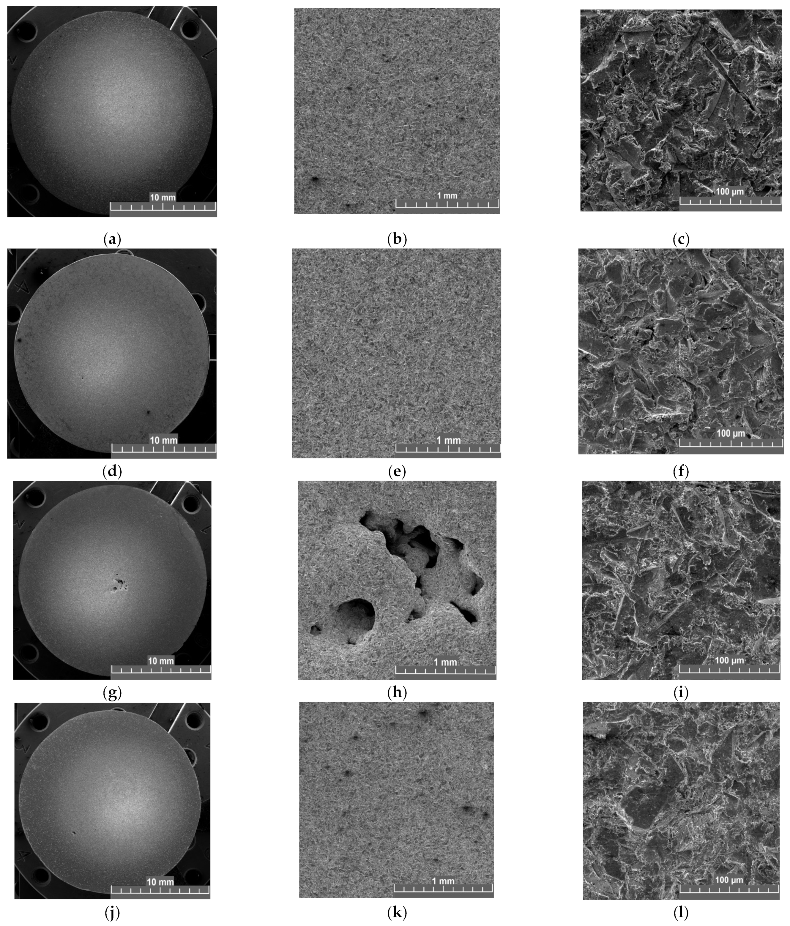
Figure 7 and Figure 8 show images of the surface topography of specimens without and with nitriding of different durations in the solid particle erosion region at flow impact angles of 30° and 90°.
The microscopic analysis of the specimen surfaces after the test showed that the character of the surface microrelief change is generally identical for all the studied specimens (see Figure 7 and Figure 8). The central parts of the specimens subjected to the greatest wear during the test can be considered morphologically as a single surface of fracture. Numerous erosion damage, such as multidirectional traces of microfractures left by abrasive particles, are observed on the surfaces. The typical length of such traces is up to 20–30 μm. Brittle–ductile failure occurs in the vicinity of these traces, while signs of plastic deformation preceding fracture are observed at the edges of the traces.
Some differences exist in the surface morphology of specimens tested at impact angles of 30° and 90°. The differences are caused by the flow path of the abrasive particles. The shapes of the abrasive particle traces on specimens impacted at an angle of 30° are more elongated as the material is scratched by the impact of the angled particles on the surface.
Comparison of the untreated and nitrided specimens shows that there is no fundamental difference in the nature of the microfractures on the surface. This indirectly indicates that the surfaces after nitriding, despite the increased hardness, retain a high enough plasticity margin and do not break under the impact of an abrasive.
4. Conclusions
As a result of the experimental studies, solid particle erosion at different air-abrasive flow impact angles was obtained for 30 L steel without hardening, with three types of nitriding and with two types of boriding, at flow angles of 30 and 90 degrees.
The obtained kinetic curves of the solid particle erosion for all the studied types of nitriding showed that this method of surface modification does not affect the solid particle erosion resistance of 30 L steel at an impact angle of 90°, while at an impact angle of 30° it increases the resistance of 30 L steel by at least 10–20%. This indicates the promising use of this method of surface modification for the protection of critical elements of the flow part of hydraulic turbines.
The research results demonstrated that boriding processes worsen the solid particle erosion resistance of 30 L steel at flow angles of 30 and 90 degrees due to embrittlement of the surface. In turn, the previously obtained data [102] on the multiple increase in solid particle erosion resistance of 20 GL steel with boriding indicate a significant influence of the chemical composition of steel, in particular the percentage of carbon and manganese, on the strength characteristics of the surface after boriding.
Author Contributions
Conceptualization, A.M., O.Z. and A.T.; methodology, O.Z.; experiment, A.M. and A.T.; validation, A.M.; formal analysis, O.Z.; investigation, A.M.; data curation, O.Z. and A.M; writing—original draft preparation, O.Z. and A.M.; writing—review and editing, A.T.; visualization, O.Z. and A.M.; supervision, O.Z.; project administration, A.M. and A.T.; funding acquisition, O.Z. and A.M. All authors have read and agreed to the published version of the manuscript.
Funding
The work was conducted in the framework of proactive research on “Study to improve the thermal-hydraulic properties and wear resistance of functional surfaces of power equipment”.
Institutional Review Board Statement
Not applicable.
Informed Consent Statement
Not applicable.
Data Availability Statement
Data are contained within the article.
Conflicts of Interest
The authors declare no conflict of interest.
References
- Zhang, Y.; Qian, Z.; Ji, B.; Wu, Y. A review of microscopic interactions between cavitation bubbles and particles in silt-laden flow. Renew. Sustain. Energy Rev. 2016, 56, 303–318. [Google Scholar] [CrossRef]
- Yi, J.Z.; Hu, H.X.; Wang, Z.B.; Zheng, Y.G. On the critical flow velocity for erosion-corrosion in local eroded regions under liquid-solid jet impingement. Wear 2019, 422–423, 94–99. [Google Scholar] [CrossRef]
- Bregliozzi, G.; Di Schino, A.; Ahmed, S.I.-U.; Kenny, J.M.; Haefke, H. Cavitation wear behaviour of austenitic stainless steels with different grain sizes. Wear 2005, 258, 503–510. [Google Scholar] [CrossRef]
- Ghiban, B.; Safta, C.-A.; Ion, M.; Crângașu, C.E.; Grecu, M.-C. Structural Aspects of Silt Erosion Resistant Materials Used in Hydraulic Machines Manufacturing. Energy Proc. 2017, 112, 75–82. [Google Scholar] [CrossRef]
- Wang, L.; Wang, H.; Wang, D. The Applied Research of Hydroturbine Prime mover and Governor Modeling of in the Yunnan Power Grid. Proc. Eng. 2011, 23, 765–768. [Google Scholar] [CrossRef]
- Kang, Z.; Feng, C.; Liu, Z.; Cang, Y.; Gao, S. Analysis of the incipient cavitation noise signal characteristics of hydro-turbine. Appl. Acoust. 2017, 127, 118–125. [Google Scholar] [CrossRef]
- Babu, A.; Perumal, G.; Arora, H.S.; Grewal, H.S. Enhanced slurry and cavitation erosion resistance of deep cryogenically treated thermal spray coatings for hydroturbine applications. Renew. Energy 2021, 180, 1044–1055. [Google Scholar] [CrossRef]
- Hamilton, A.; Sharma, A.; Pandel, U. Effect of impingement velocity on solid particle erosion behaviour of CA6NM hydroturbine steel. Mater. Today Proc. 2018, 5 Pt 1, 17325–17332. [Google Scholar] [CrossRef]
- Sharma, S.; Gandhi, B.K. Assessment of erosion wear in low specific speed Francis turbine due to particulate flow. Adv. Powder Technol. 2023, 34, 104065. [Google Scholar] [CrossRef]
- Zhang, Y.; Liu, K.; Xian, H.; Du, X. A review of methods for vortex identification in hydroturbines. Renew. Sustain. Energy Rev. 2018, 81, 1269–1285. [Google Scholar] [CrossRef]
- Krella, A.K. Degradation and Protection of Materials from Cavitation Erosion: A Review. Materials 2023, 16, 2058. [Google Scholar] [CrossRef] [PubMed]
- Liu, X.; Luo, Y.; Karney, B.W.; Wang, W. A selected literature review of efficiency improvements in hydraulic turbines. Renew. Sustain. Energy Rev. 2015, 51, 18–28. [Google Scholar] [CrossRef]
- Natsume, M.; Hayashi, Y.; Akebono, H.; Kato, M.; Sugeta, A. Fatigue properties and crack propagation behavior of stainless cast steel for turbine runner of hydraulic power generation. Proc. Eng. 2010, 2, 1273–1281. [Google Scholar] [CrossRef]
- Gabaidulin, D.Y.; Grechneva, M.V. Resources to repaire hydroturbine blades affected by cavitation. Vestnik IrGTU 2012, 12, 40–43. [Google Scholar]
- Georgievskaia, E. Justification of the hydraulic turbines lifetime from the standpoint of the fracture mechanics. Procedia Struct. Integr. 2018, 13, 971–975. [Google Scholar] [CrossRef]
- Gohil, P.P.; Saini, R.P. Investigation into cavitation damage potentiality using pressure pulsation phenomena in a low head Francis turbine for small hydropower schemes. Ocean Eng. 2022, 263, 112230. [Google Scholar] [CrossRef]
- Yu, A.; Zou, Z.; Zhou, D.; Zheng, Y.; Luo, X. Investigation of the correlation mechanism between cavitation rope behavior and pressure fluctuations in a hydraulic turbine. Renew. Energy 2020, 147, 1199–1208. [Google Scholar] [CrossRef]
- Haiko, O.; Kaikkonen, P.; Somani, M.; Valtonen, K.; Kömi, J. Characteristics of carbide-free medium-carbon bainitic steels in high-stress abrasive wear conditions. Wear 2020, 456–457, 203386. [Google Scholar] [CrossRef]
- Chowdhury, M.A.; Hossain, N.; Shahin, M.; Debnath, U.K.; Rahman, M.; Rahman, M.M. Erosion characteristics of stainless steels under different percentage of SiC-Al2O3-Fe2O3 solid particles. Tribol. Int. 2022, 167, 107403. [Google Scholar] [CrossRef]
- Saad, J.; Ghahramani, E.; Neuhauser, M.; Bourgeois, S.; Bensow, R.E.; Poelma, C. Experimental investigation of cavitation-induced erosion around a surface-mounted bluff body. Wear 2021, 480–481, 203917. [Google Scholar]
- Ai, Y.; Han, S.; Lei, C.; Cheng, J. The characteristics extraction of weld seam in the laser welding of dissimilar materials by different image segmentation methods. Opt. Laser Technol. 2023, 167, 109740. [Google Scholar] [CrossRef]
- Ai, Y.; Yan, Y.; Dong, G.; Han, S. Investigation of microstructure evolution process in circular shaped oscillating laser welding of Inconel 718 superalloy. Int. J. Heat Mass Transf. 2023, 216, 124522. [Google Scholar] [CrossRef]
- Hutli, E.; Fekete, T.; Nedeljkovic, M. Surface characteristics and cavitation damage progress in ductile materials. Eng. Fail. Anal. 2019, 106, 104157. [Google Scholar] [CrossRef]
- Hu, H.X.; Guo, X.M.; Zheng, Y.G. Comparison of the cavitation erosion and slurry erosion behavior of cobalt-based and nickel-based coatings. Wear 2019, 428–429, 246–257. [Google Scholar]
- Li, Z.X.; Zhang, L.M.; Ma, A.L.; Hu, J.X.; Zhang, S.; Daniel, E.F.; Zheng, Y.G. Comparative study on the cavitation erosion behavior of two different rolling surfaces on 304 stainless steel. Tribol. Int. 2021, 159, 106994. [Google Scholar] [CrossRef]
- Cheng, F.; Ji, W.; Qian, C.; Xu, J. Cavitation bubbles dynamics and cavitation erosion in water jet. Results Phys. 2018, 9, 1585–1593. [Google Scholar] [CrossRef]
- Khare, R.; Prasad, V. Prediction of cavitation and its mitigation techniques in hydraulic turbines—A review. Ocean Eng. 2021, 221, 108512. [Google Scholar]
- Muñoz-Cubillos, J.; Coronado, J.J.; Rodríguez, S.A. On the cavitation resistance of deep rolled surfaces of austenitic stainless steels. Wear 2019, 428–429, 24–31. [Google Scholar] [CrossRef]
- Dular, M.; Petkovšek, M. Cavitation erosion in liquid nitrogen. Wear 2018, 400, 111–118. [Google Scholar] [CrossRef]
- Wrede, A.H.; Shah, A.; McNamara, M.C.; Montazami, R.; Hashemi, N.N. Controlled positioning of microbubbles and induced cavitation using a dual-frequency transducer and microfiber adhesion techniques. Ultrason. Sonochem. 2018, 43, 114–119. [Google Scholar] [CrossRef] [PubMed]
- Fang, Y.; Yamamoto, T.; Komarov, S. Cavitation and acoustic streaming generated by different sonotrode tips. Ultrason. Sonochem. 2018, 48, 79–87. [Google Scholar] [CrossRef] [PubMed]
- Peng, K.; Tian, S.; Li, G.; Huang, Z.; Zhang, Z. Cavitation in water jet under high ambient pressure conditions. Exp. Therm. Fluid Sci. 2017, 89, 9–18. [Google Scholar] [CrossRef]
- Sreedhar, B.K.; Albert, S.K.; Pandit, A.B. Cavitation damage: Theory and measurements—A review. Wear 2017, 372–373, 177–196. [Google Scholar] [CrossRef]
- Sarkar, P.; Ghigliotti, G.; Franc, J.-P.; Fivel, M. Mechanism of material deformation during cavitation bubble collapse. J. Fluids Struct. 2021, 105, 103327. [Google Scholar] [CrossRef]
- Schreiner, F.; Hanke, S.; Skoda, R. Assessment of flow aggressiveness and erosion damage topography for different gap widths in ultrasonic cavitation testing. Wear 2021, 484–485, 203989. [Google Scholar] [CrossRef]
- Hutli, E.; Nedeljkovic, M.S.; Radovic, N.A.; Bonyár, A. The relation between the high speed submerged cavitating jet behaviour and the cavitation erosion process. Int. J. Multiph. Flow 2016, 83, 27–38. [Google Scholar] [CrossRef]
- Xu, W.; Wang, Q.; Wei, W.; Luo, J.; Chen, S. Effects of air bubble quantity on the reduction of cavitation erosion. Wear 2021, 482–483, 203937. [Google Scholar] [CrossRef]
- Cai, T.; Pan, Y.; Ma, F. Effects of nozzle lip geometry on the cavitation erosion characteristics of self-excited cavitating waterjet. Exp. Therm. Fluid Sci. 2020, 117, 110137. [Google Scholar] [CrossRef]
- Ge, M.; Petkovšek, M.; Zhang, G.; Jacobs, D.; Coutier-Delgosha, O. Cavitation dynamics and thermodynamic effects at elevated temperatures in a small Venturi channel. Int. J. Heat Mass Transf. 2021, 170, 120970. [Google Scholar] [CrossRef]
- Liu, B.; Ma, F. Erosion behavior of aluminum by an inclined cavitating jet. Wear 2021, 474, 203751. [Google Scholar] [CrossRef]
- Li, J.-B.; Xu, W.-L.; Zhai, Y.-W.; Luo, J.; Wu, H.; Deng, J. Influence of multiple air bubbles on the collapse strength of a cavitation bubble. Exp. Therm. Fluid Sci. 2021, 123, 110328. [Google Scholar] [CrossRef]
- Sun, Z.C.; Mao, Y.F.; Fan, M.H. Performance optimization and investigation of flow phenomena on tidal turbine blade airfoil considering cavitation and roughness. Appl. Ocean Res. 2021, 106, 102463. [Google Scholar] [CrossRef]
- Pan, Y.; Ma, F.; Liu, B.; Cai, T. Cavitation intensity and erosion pattern of a self-excited cavitating jet. J. Mater. Process. Technol. 2020, 282, 116668. [Google Scholar] [CrossRef]
- Fujisawa, N.; Horiuchi, T.; Fujisawa, K.; Yamagati, T. Experimental observation of the erosion pattern, pits, and shockwave formation in a cavitating jet. Wear 2019, 418, 265–272. [Google Scholar] [CrossRef]
- Fujisawa, N.; Fujita, Y.; Yanagisawa, K.; Fujisawa, K.; Yamagati, T. Simultaneous observation of cavitation collapse and shock wave formation in cavitating jet. Exp. Therm. Fluid Sci. 2018, 94, 159–167. [Google Scholar] [CrossRef]
- Kang, C.; Liu, H.; Soyama, H. Estimation of aggressive intensity of a cavitating jet with multiple experimental methods. Wear 2018, 394–395, 176–186. [Google Scholar] [CrossRef]
- Qiu, N.; Wang, L.; Wu, S.; Likhachev, D.S. Research on cavitation erosion and wear resistance performance of coatings. Eng. Fail. Anal. 2015, 55, 208–223. [Google Scholar] [CrossRef]
- Alidokht, S.A.; Vo, P.; Yue, S.; Chromik, R.R. Erosive wear behavior of Cold-Sprayed Ni-WC composite coating. Wear 2017, 376–377, 566–577. [Google Scholar] [CrossRef]
- Karmakar, D.P.; Muvvala, G.; Nath, A.K. High-temperature abrasive wear characteristics of H13 steel modified by laser remelting and cladded with Stellite 6 and Stellite 6/30% WC. Surf. Coat. Technol. 2021, 422, 127498. [Google Scholar] [CrossRef]
- Ordoñez, M.F.C.; Amorim, C.L.G.; Krindges, I.; Aguzzoli, C.; Baumvol, I.J.R.; Figueroa, C.A.; Sinatora, A.; Souza, R.M.; Farias, M.C.M. Microstructure and micro-abrasive wear of sintered yttria-containing 316L stainless steel treated by plasma nitriding. Surf. Coat. Technol. 2019, 374, 700–712. [Google Scholar] [CrossRef]
- Sun, S.D.; Fabijanic, D.; Annasamy, M.; Corujeira, G.S.C.; Fordyce, I.; Paradowska, A.; Leary, M.; Easton, M.; Brandt, M. Microstructure, abrasive wear and corrosion characterisation of laser metal deposited Fe-30Cr-6Mo-10Ni-2.2C alloy. Wear 2019, 438–439, 203070. [Google Scholar] [CrossRef]
- Bonu, V.; Jeevitha, M.; Kumar, V.P.; Srinivas, G.; Siju, B.H.C. Solid particle erosion and corrosion resistance performance of nanolayeredmultilayered Ti/TiN and TiAl/TiAlN coatings deposited on Ti6Al4V Substrates. Surf. Coat. Technol. 2020, 387, 125531. [Google Scholar] [CrossRef]
- Nguyen, Q.B.; Nguyen, D.N.; Murray, R.; Ca, N.X.; Lim, C.Y.H.; Gupta, M.; Nguyen, X.C. The role of abrasive particle size on erosion characteristics of stainless steel. Eng. Fail. Anal. 2019, 97, 844–853. [Google Scholar] [CrossRef]
- Yang, C.; Zhu, J.; Cui, S.; Chen, P.; Wu, Z.; Ma, Z.; Fu, R.K.Y.; Tian, X.; Chu, P.K.; Wu, Z. Wear and corrosion resistant coatings prepared on LY12 aluminum alloy by plasma electrolytic oxidation. Surf. Coat. Technol. 2021, 409, 126885. [Google Scholar] [CrossRef]
- Zhao, X.; Tang, G.H.; Liu, Z.; Zhang, Y.W. Finite element analysis of anti-erosion characteristics of material with patterned surface impacted by particles. Powder Technol. 2019, 342, 193–203. [Google Scholar] [CrossRef]
- Ma, A.; Liu, D.; Zhang, X.; Liu, D.; He, G.; Yin, X. Solid particle erosion behavior and failure mechanism of TiZrN coatings for Ti-6Al-4V alloy. Surf. Coat. Technol. 2021, 426, 127701. [Google Scholar] [CrossRef]
- Dhillon, S.S.; Chawla, V.; Singh, G. Analysis of solid particle erosion in plasma sprayed alumina based coatings on SAE-347H steel. Mater. Today Proc. 2022, 50, 1210–1220. [Google Scholar] [CrossRef]
- Bonu, V.; Kumar, S.; Sooraj, P.N.; Barshilia, H.C. A novel solid particle erosion resistant Ti/TiN multilayer coating with additional energy absorbing nano-porous metal layers: Validation by FEM analysis. Mater. Des. 2021, 198, 109389. [Google Scholar] [CrossRef]
- Pal, S.; Nair, R.B.; McDonald, A. Effect of tungsten and vanadium additions on the dry abrasive wear and solid particle erosion of flame-sprayed AlCoCrFeMo high entropy alloy coatings. Int. J. Refract. Met. Hard Mater. 2023, 114, 106245. [Google Scholar] [CrossRef]
- Yang, H.; Zhang, M.; Chen, R.; Liu, Q.; Liu, J.; Yu, J.; Zhang, H.; Liu, P.; Lin, C.; Wang, J. Polyurethane coating with heterogeneity structure induced by microphase separation: A new combination of antifouling and cavitation erosion resistance. Prog. Org. Coat. 2021, 151, 106032. [Google Scholar] [CrossRef]
- Xu, J.; Peng, S.; Li, Z.; Jiang, S.; Xie, Z.-H.; Munroe, P. The influence of semiconducting properties of passive films on the cavitation erosion resistance of a NbN nanoceramic coating. Ultrason. Sonochem. 2021, 71, 105406. [Google Scholar] [CrossRef] [PubMed]
- Zhang, R.-Z.; Ren, Y.-Y.; Yan, D.-K.; Guo, P.-Y.; Li, L.-J. Synthesis of hydrophobic fluorinated polyurethanes and their properties of resistance to cavitation and wear. Prog. Org. Coat. 2017, 104, 11–19. [Google Scholar] [CrossRef]
- Lavigne, S.; Pougoum, F.; Savoie, S.; Martinu, L.; Klemberg-Sapieha, J.E.; Schulz, R. Cavitation erosion behavior of HVOF CaviTec coatings. Wear 2017, 386–387, 90–98. [Google Scholar] [CrossRef]
- Ding, X.; Huang, Y.; Yuan, C.; Ding, Z. Deposition and cavitation erosion behavior of multimodal WC-10Co4Cr coatings sprayed by HVOF. Surf. Coat. Technol. 2020, 392, 125757. [Google Scholar] [CrossRef]
- Du, J.; Zhang, J.; Xu, J.; Zhang, C. Cavitation-corrosion behaviors of HVOF sprayed WC-25WB-10Co-5NiCr and MoB-25NiCr coatings. Ceram. Int. 2020, 46, 21707–21718. [Google Scholar] [CrossRef]
- Hong, S.; Lin, J.; Wu, Y.; Wu, J.; Zheng, Y.; Zhang, Y.; Cheng, J.; Sun, W. Cavitation erosion characteristics at various flow velocities in NaCl medium of carbide-based cermet coatings prepared by HVOF spraying. Ceram. Int. 2021, 47, 1929–1939. [Google Scholar] [CrossRef]
- Lamana, M.S.; Pukasiewicz, A.G.M.; Sampath, S. Influence of cobalt content and HVOF deposition process on the cavitation erosion resistance of WC-Co coatings. Wear 2018, 398–399, 209–219. [Google Scholar] [CrossRef]
- Kumar, H.; Chittosiya, C.; Shukla, V.N. HVOF Sprayed WC Based Cermet Coating for Mitigation of Cavitation, Erosion & Abrasion in Hydro Turbine Blade. Mater. Today. Proc. 2018, 5, 6413–6420. [Google Scholar]
- Qiao, L.; Wu, Y.; Hong, S.; Zhang, J.; Shi, W.; Zheng, Y. Relationships between spray parameters, microstructures and ultrasonic cavitation erosion behavior of HVOF sprayed Fe-based amorphous/nanocrystalline coatings. Ultrason. Sonochem. 2017, 39, 39–46. [Google Scholar] [CrossRef]
- Pukasiewicz, A.G.M.; de Boer, H.E.; Sucharski, G.B.; Vaz, R.F.; Procopiak, L.A.J. The influence of HVOF spraying parameters on the microstructure, residual stress and cavitation resistance of FeMnCrSi coatings. Surf. Coat. Technol. 2017, 327, 158–166. [Google Scholar] [CrossRef]
- Qiao, L.; Wu, Y.; Hong, S.; Cheng, J. Ultrasonic cavitation erosion mechanism and mathematical model of HVOF sprayed Fe-based amorphous/nanocrystalline coatings. Ultrason. Sonochem. 2019, 52, 142–149. [Google Scholar] [CrossRef]
- Silveira, L.L.; Pukasiewicz, A.G.M.; de Aguiar, D.J.M.; Zara, A.J.; Björklund, S. Study of the corrosion and cavitation resistance of HVOF and HVAF FeCrMnSiNi and FeCrMnSiB coatings. Surf. Coat. Technol. 2019, 374, 910–922. [Google Scholar] [CrossRef]
- Taillon, G.; Pougoum, F.; Lavigne Ton-That, S.L.; Schulz, R.; Bousser, E.; Savoie, S.; Martinu, L.; Klemberg-Sapieha, J.-E. Cavitation erosion mechanisms in stainless steels and in composite metal–ceramic HVOF coatings. Wear 2016, 364–365, 201–210. [Google Scholar] [CrossRef]
- Wei, Z.; Wu, Y.; Hong, S.; Cheng, J.; Qiao, L.; Cheng, J.; Zhu, S. Effect of WC-10Co on cavitation erosion behaviors of AlCoCrFeNi coatings prepared by HVOF spraying. Ceram. Int. 2021, 47, 15121–15128. [Google Scholar] [CrossRef]
- Ding, X.; Cheng, X.; Yu, X.; Li, C.; Yuan, C.; Ding, Z. Structure and cavitation erosion behavior of HVOF sprayed multi-dimensional WC–10Co4Cr coating. Trans. Nonferrous Met. Soc. China 2018, 28, 487–494. [Google Scholar] [CrossRef]
- Kanno, A.; Takagi, K.; Arai, M. Influence of chemical composition, grain size, and spray condition on cavitation erosion resistance of high-velocity oxygen fuel thermal-sprayed WC cermet coatings. Surf. Coat. Technol. 2020, 394, 125881. [Google Scholar] [CrossRef]
- Matikainen, V.; Koivuluoto, H.; Vuoristo, P. A study of Cr3C2-based HVOF- and HVAF-sprayed coatings: Abrasion, dry particle erosion and cavitation erosion resistance. Wear 2020, 446–447, 203188. [Google Scholar] [CrossRef]
- Xu, J.; Peng, S.; Li, Z.; Jiang, S.; Xie, Z.-H.; Munroe, P.; Lu, H. Remarkable cavitation erosion–corrosion resistance of CoCrFeNiTiMo high-entropy alloy coatings. Corros. Sci. 2021, 190, 109663. [Google Scholar] [CrossRef]
- Singh, K.; Ang, A.S.M.; Mahajan, D.K. Cavitation erosion resistant nickel-based cermet coatings for monel K-500. Tribol. Int. 2021, 159, 106954. [Google Scholar] [CrossRef]
- Liu, Q.; Li, Z.; Du, S.; He, Z.; Han, J.; Zhang, Y. Cavitation erosion behavior of GH 4738 nickel-based superalloy. Tribol. Int. 2021, 156, 106833. [Google Scholar] [CrossRef]
- Wang, Y.; Hao, E.; An, Y.; Chen, J.; Zhou, H. Effects of microstructure and mechanical properties on cavitation erosion resistance of NiCrWMoCuCBFe coatings. Appl. Surf. Sci. 2021, 547, 149125. [Google Scholar] [CrossRef]
- Ma, D.; Harvey, T.J.; Wellman, R.G.; Ehiasarian, A.P.; Hovsepian PEh Sugumaran, A.A.; Purandare, Y.P.; Wood, R.J.K. Cavitation erosion performance of CrAlYN/CrN nanoscale multilayer coatings deposited on Ti6Al4V by HIPIMS. J. Alloys Compd. 2019, 788, 719–728. [Google Scholar] [CrossRef]
- Hong, S.; Wu, Y.; Wu, J.; Zheng, Y.; Zhang, Y.; Cheng, J.; Li, J.; Lin, J. Effect of flow velocity on cavitation erosion behavior of HVOF sprayed WC-10Ni and WC-20Cr3C2–7Ni coatings. Int. J. Refract. Met. Hard Mater. 2020, 92, 105330. [Google Scholar] [CrossRef]
- Ma, D.; Harvey, T.J.; Zhuk, Y.N.; Wellman, R.G.; Wood, R.J.K. Cavitation erosion performance of CVD W/WC coatings. Wear 2020, 452–453, 203276. [Google Scholar] [CrossRef]
- Wang, Y.; Liu, J.; Kang, N.; Darut, G.; Poirier, T.; Stella, J.; Liao, H.; Planche, M.P. Cavitation erosion of plasma-sprayed CoMoCrSi coatings. Tribol. Int. 2016, 102, 429–435. [Google Scholar] [CrossRef]
- Krella, A.K.; Czyżniewski, A.; Gilewicz, A.; Krupa, A. Cavitation erosion of CrN/CrCN multilayer coating. Wear 2017, 386–387, 80–89. [Google Scholar] [CrossRef]
- Romero, M.C.; Tschiptschin, A.P.; Scandian, C. Low temperature plasma nitriding of a Co30Cr19Fe alloy for improving cavitation erosion resistance. Wear 2019, 426–427, 581–588. [Google Scholar] [CrossRef]
- Wang, Z.; Zhang, B. Cavitation erosion behavior of high nitrogen austenitic stainless steel: Effect and design of grain-boundary characteristics. Mater. Des. 2021, 201, 109496. [Google Scholar] [CrossRef]
- Liu, Z.; Zhu, S.; Shen, M.; Jia, Y.; Wang, W.; Wang, F. Microstructure and cavitation erosion behavior of sputtered NiCrAlTi coatings with and without N incorporations. J. Mater. Sci. Technol. 2020, 54, 211–222. [Google Scholar] [CrossRef]
- Mitelea, I.; Dimian, E.; Bordeaşu, I.; Crăciunescu, C. Ultrasonic cavitation erosion of gas nitrided Ti–6Al–4V alloys. Ultrason. Sonochem. 2014, 21, 1544–1548. [Google Scholar] [CrossRef] [PubMed]
- Qiao, Y.; Chena, J.; Zhou, H.; Wang, Y.; Song, Q.; Li, H.; Zheng, Z. Effect of solution treatment on cavitation erosion behavior of high-nitrogen austenitic stainless steel. Wear 2019, 424–425, 70–77. [Google Scholar] [CrossRef]
- Cruz, J.R.; Henke, S.L.; Pukasiewicz, A.G.M. The effect of boron on cavitation resistance of FeCrMnSiB austenitic stainless steels. Wear 2019, 436–437, 203041. [Google Scholar] [CrossRef]
- Tsikh, S.G.; Martynov, V.N.; Shklyar, N.E. Liquid boring. Rhythm 2015, 6, 38–40. [Google Scholar]
- Türkmen, İ.; Kanbur, K.; Sargin, F. Characteristics of boronized Ti6Al4V alloy using boric acid based boronizing. Mater. Charact. 2022, 192, 112180. [Google Scholar] [CrossRef]
- Kayalıa, Y.; Kancab, E.; Günenc, A. Effect of boronizing on microstructure, high-temperature wear and corrosion behavior of additive manufactured Inconel 718. Mater. Charact. 2022, 191, 112155. [Google Scholar] [CrossRef]
- Nath, G.; Kumar, S. Slurry Erosion Behaviour of Pack Boronized 13-4 Martensitic Stainless Steel for Hydro Turbine Blades. Maert. Today Proc. 2018, 5, 17380–17388. [Google Scholar] [CrossRef]
- Park, I.C.; Lee, H.K.; Kim, S.J. Microstructure and cavitation damage characteristics of surface treated gray cast iron by plasma ion nitriding. App. Surf. Sci. 2019, 477, 147–153. [Google Scholar] [CrossRef]
- Vitry, V.; Hastir, J.; Mégret, A.; Yazdani, S.; Yunacti, M.; Bonin, L. Recent advances in electroless nickel-boron coatings. Surf. Coatings Technol. 2022, 429, 127937. [Google Scholar] [CrossRef]
- Saenz-Betancourt, C.C.; Rodríguez, S.A.; Coronado, J.J. Effect of boronising on the cavitation erosion resistance of stainless steel used for hydromachinery applications. Wear 2022, 498, 204330. [Google Scholar] [CrossRef]
- Mitelea, I.; Bordeaşu, I.; Belin, C.; Uţu, I.-D.; Crăciunescu, C.M. Cavitation Resistance, Microstructure, and Surface Topography of Plasma Nitrided Nimonic 80 A Alloy. Materials 2022, 15, 6654. [Google Scholar] [CrossRef] [PubMed]
- Tkhabisimov, A.B.; Zilova, O.S.; Skobelev, K.D.; Kalakutskaya, O.V. Investigation into the Influence of jet cavitation impact on changes in characteristics of the surface of structural steel 30L and 20GL. Therm. Eng. 2022, 69, 545–553. [Google Scholar] [CrossRef]
- Tkhabisimov, A.B.; Zilova, O.S.; Kalakutskaya, O.V. Research results of solid particle erosion resistance of 20GL steel with boriding. J. Phys. Conf. Ser. 2021, 2124, 012012. [Google Scholar] [CrossRef]
Figure 1.
Kinetic curves of cavitation wear of 20 GL (1) and 30 L (2) steel samples. Reprinted with permission from ref. [101]. Copyright 2022 Springer Nature.
Figure 1.
Kinetic curves of cavitation wear of 20 GL (1) and 30 L (2) steel samples. Reprinted with permission from ref. [101]. Copyright 2022 Springer Nature.
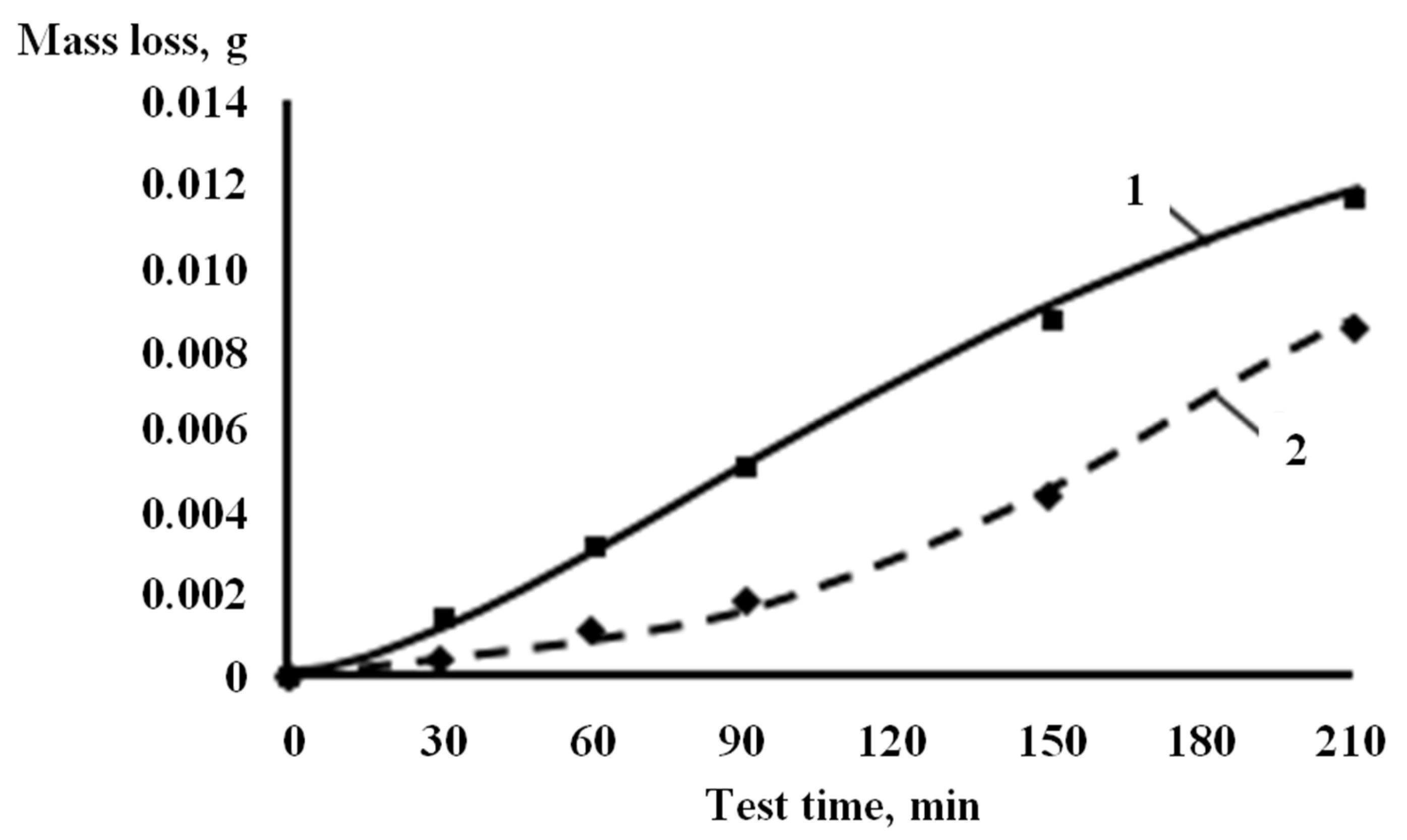
Figure 2.
Schematic diagram of an experimental rig for conducting research on the solid particle erosion resistance of materials and coatings. 1—compressor; 2—filter; 3—rotameter; 4—nozzle (Venturi tube); 5—mixing chamber; 6—particle dispenser; 7—stabilizing tube; 8—sample; 9—heating element; 10—ceramic heater; 11—thermoelectric converter; 12—sample holder for low-temperature tests; 13—rotary valve.
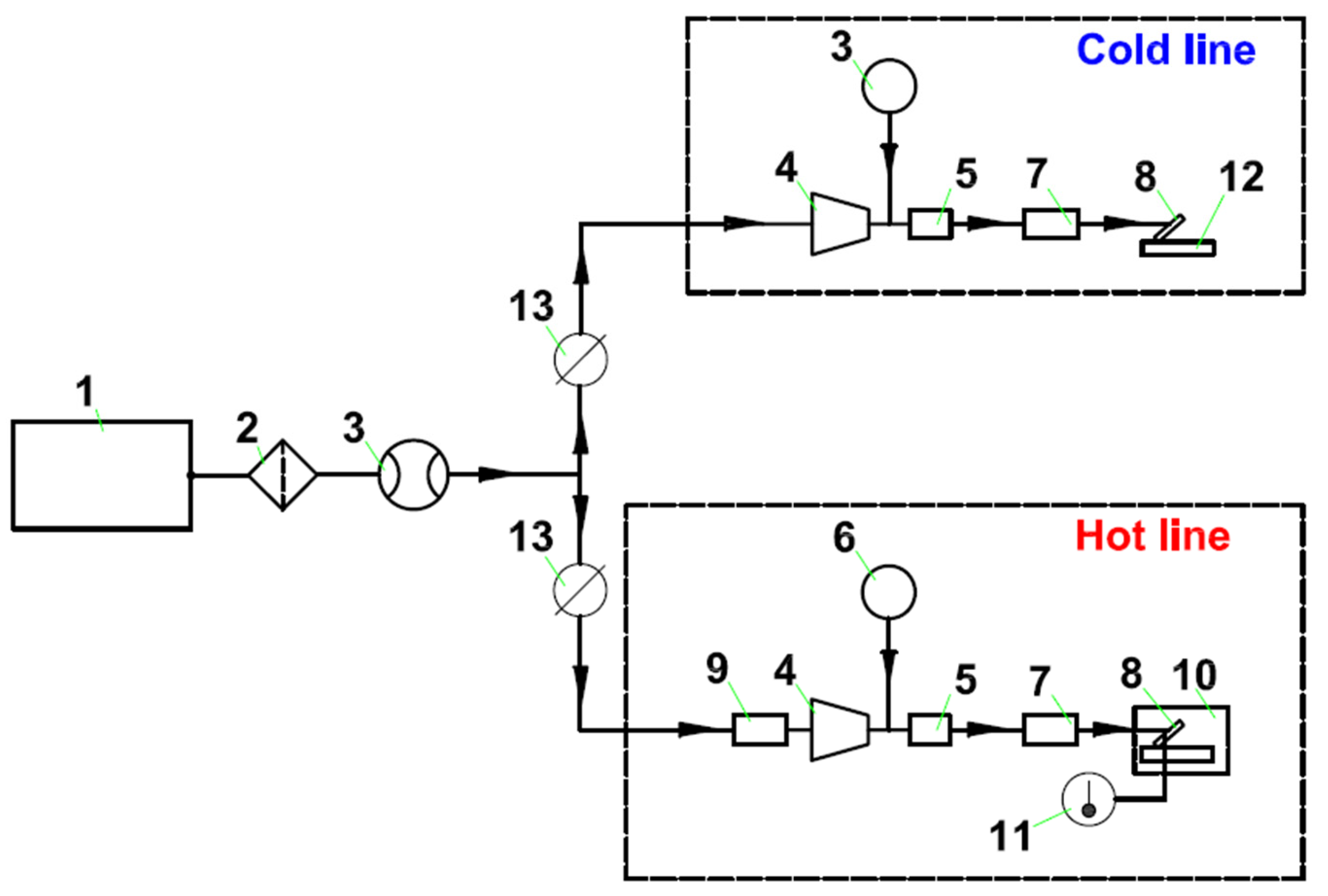
Figure 3.
Cross-section metallographic specimens of uncoated 30 L steel (a); 30 L steel with nitriding of type I (b), type II (c), and type III (d); and with boriding of type I (e) and type II (f).
Figure 3.
Cross-section metallographic specimens of uncoated 30 L steel (a); 30 L steel with nitriding of type I (b), type II (c), and type III (d); and with boriding of type I (e) and type II (f).

Figure 4.
Wear curves and relative solid particle erosion resistance during a 90-min exposure time of the uncoated specimens (1), specimens with nitriding of type I (2), type II (3), and type III (4), and specimens with boriding of type I (5) and type II (6) of 30 L steel at flow impact angles of 30° (a,b) and 90° (c,d). 5,6—high wear rate was recorded; tests were stopped after 30 min of exposure.
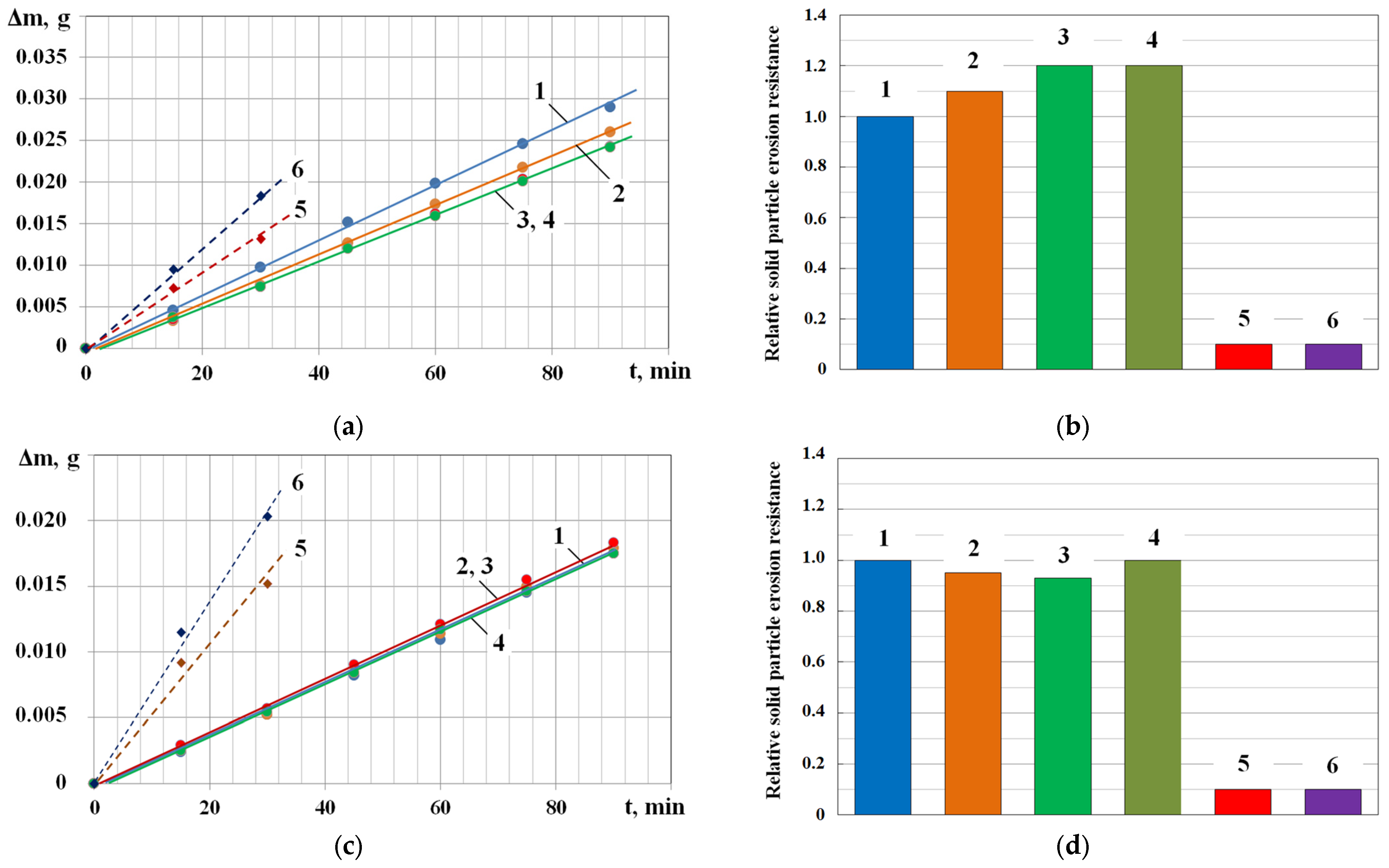
Figure 5.
Solid particle erosion curves for the uncoated specimens (a), and nitride specimens of type I (b), type II (c), and type III (d) of 30 L steel at 30° (1) and 90° (2) flow impact angles.
Figure 5.
Solid particle erosion curves for the uncoated specimens (a), and nitride specimens of type I (b), type II (c), and type III (d) of 30 L steel at 30° (1) and 90° (2) flow impact angles.
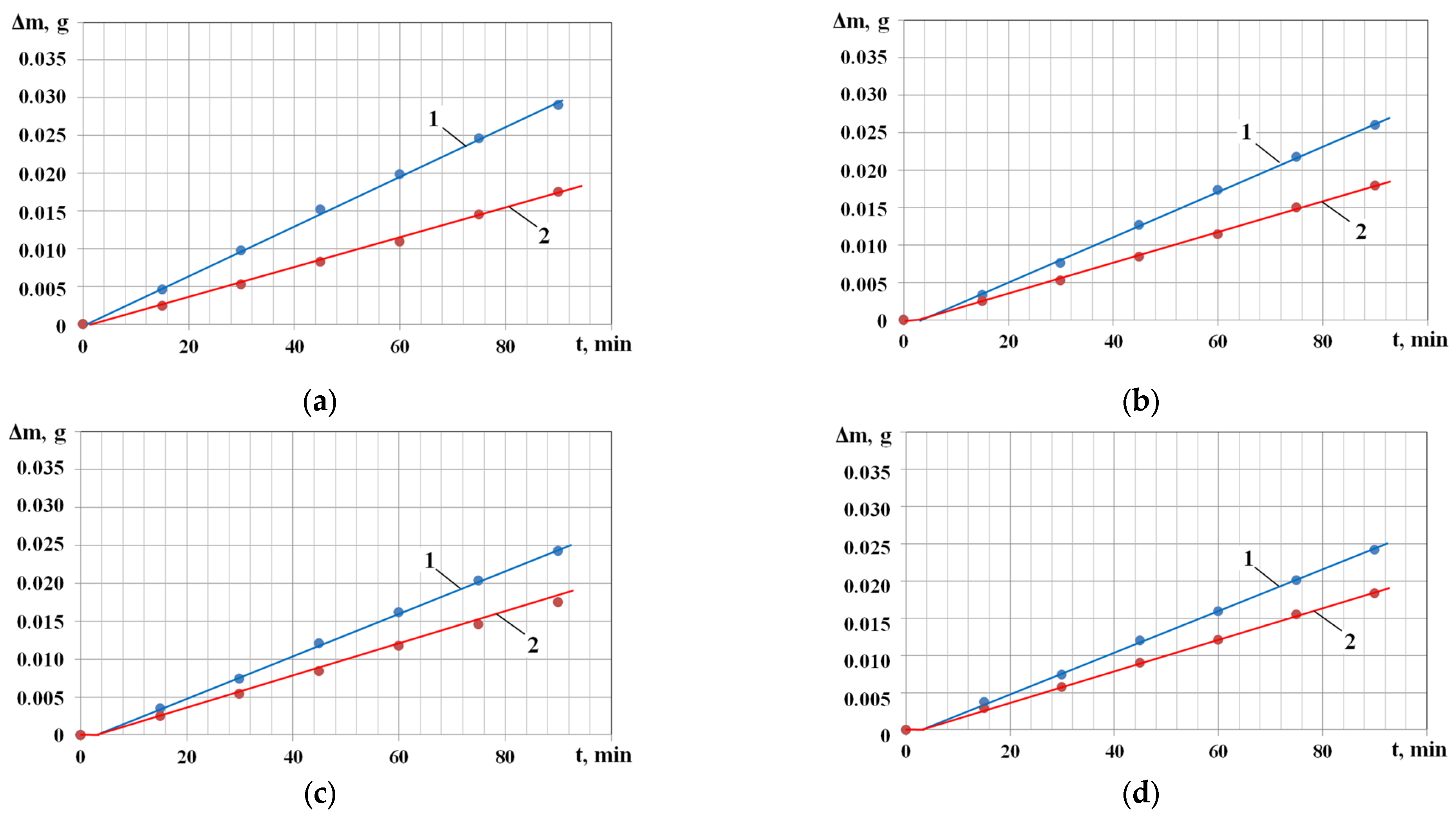
Figure 6.
The cross-sectional SEM image and EDS chart of the elemental composition analysis: (a,b) 30 L steel modified by nitriding (type III); (c,d) 30 L steel without modifying.
Figure 6.
The cross-sectional SEM image and EDS chart of the elemental composition analysis: (a,b) 30 L steel modified by nitriding (type III); (c,d) 30 L steel without modifying.
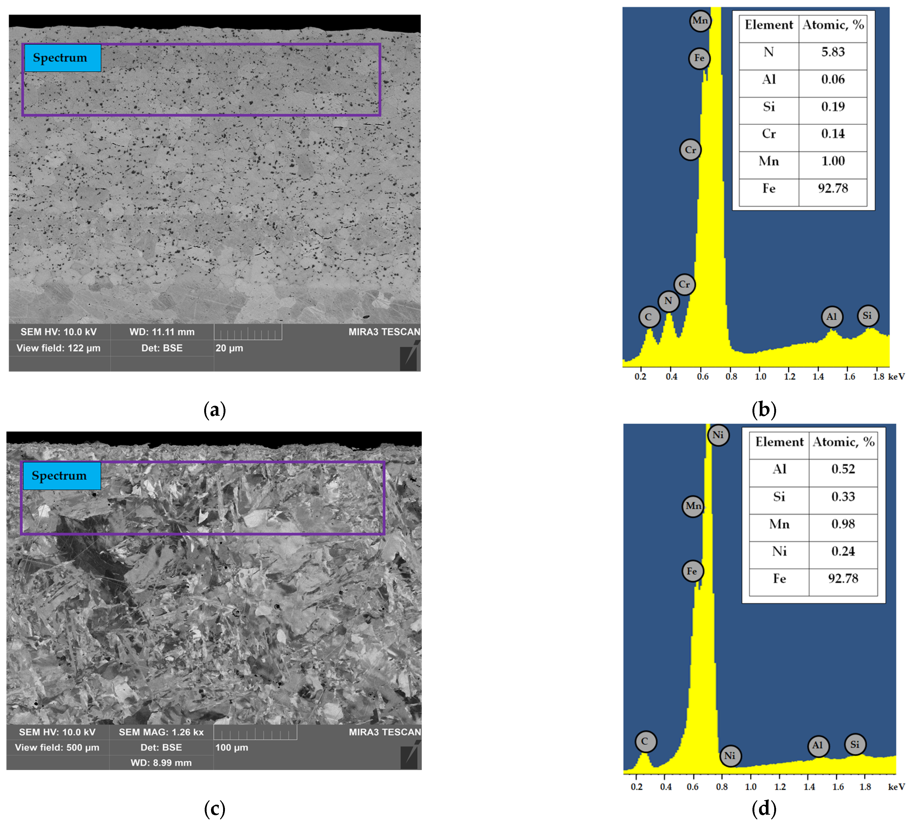
Figure 7.
Surface images of 30 L steel specimens without (a–c) and with nitriding of type I (d–f), type II (g–i), and type III (j–l) after solid particle erosion exposure at a flow impact angle of 30°.
Figure 7.
Surface images of 30 L steel specimens without (a–c) and with nitriding of type I (d–f), type II (g–i), and type III (j–l) after solid particle erosion exposure at a flow impact angle of 30°.
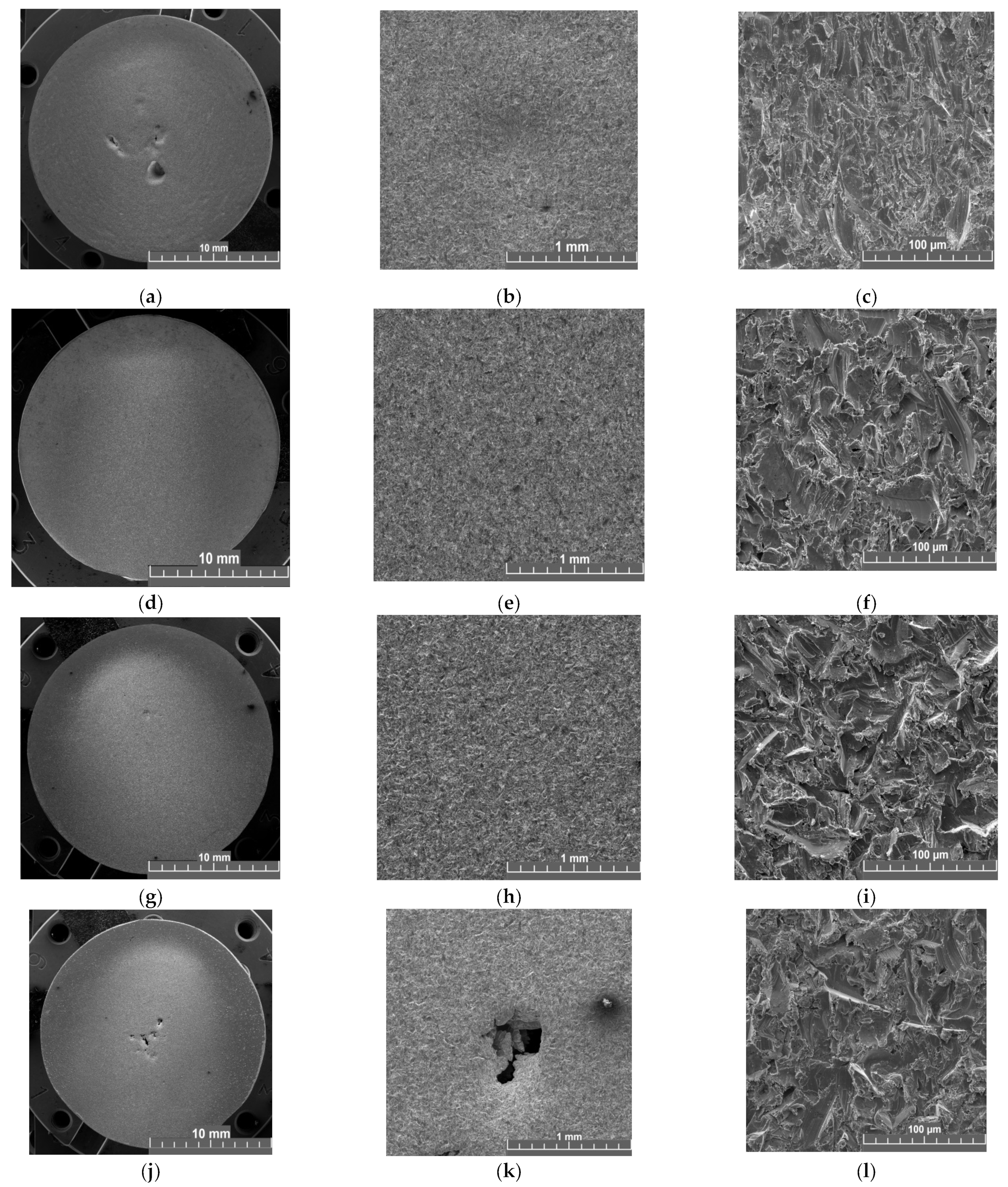
Figure 8.
Surface images of 30 L steel specimens without (a–c) and with nitriding of type I (d–f), type II (g–i), and type III (j–l) after solid particle erosion exposure at a flow impact angle of 90°.
Figure 8.
Surface images of 30 L steel specimens without (a–c) and with nitriding of type I (d–f), type II (g–i), and type III (j–l) after solid particle erosion exposure at a flow impact angle of 90°.

Table 1.
Chemical composition of steel 30 L.
| C, % wt. | Si, % wt. | Mn, % wt. | S, % wt. | P, % wt. | Fe, % wt. |
|---|---|---|---|---|---|
| 0.27–0.35 | 0.20–0.52 | 0.4–0.6 | <0.045 | <0.04 | other |
Table 2.
Parameters for solid particle erosion testing.
| Parameter | Value |
|---|---|
| Particle size of Al2O3 (electrocorundum) | 250–300 μm |
| Air-abrasive flow rate | 170 m/s |
| Particulate matter flow rate | 5 × 10⁻⁵ kg per second |
| Air-abrasive flow impact angle | 30°, 90° |
| Specimen surface temperature | 25 °C |
| Number of samples engaged in experiment | 1 |
| Total test time | 90 min |
Table 3.
Characteristics of 30 L steel specimens with different types of surface modification.
| Material | Modification | Type of Modification | Duration of Modification, h | HV0.01 | Depth of Modified Layer, μm |
|---|---|---|---|---|---|
| 30 L | Nitriding | I | 2.5 | 333 ± 18 | 35 ± 5 |
| II | 5 | 438 ± 18 | 65 ± 5 | ||
| III | 10 | 480 ± 30 | 80 ± 5 | ||
| Boriding | I | 3 | 2010 ± 60 | 80 ± 5 | |
| II | 6 | 2180 ± 40 | 150 ± 5 |
Disclaimer/Publisher’s Note: The statements, opinions and data contained in all publications are solely those of the individual author(s) and contributor(s) and not of MDPI and/or the editor(s). MDPI and/or the editor(s) disclaim responsibility for any injury to people or property resulting from any ideas, methods, instructions or products referred to in the content. |
© 2023 by the authors. Licensee MDPI, Basel, Switzerland. This article is an open access article distributed under the terms and conditions of the Creative Commons Attribution (CC BY) license (https://creativecommons.org/licenses/by/4.0/).
Share and Cite
MDPI and ACS Style
Tkhabisimov, A.; Mednikov, A.; Zilova, O. Studies of the Solid Particle Erosion Resistance of 30 L Steel with Different Types of Surface Modification. Metals 2023, 13, 1978. https://doi.org/10.3390/met13121978
AMA Style
Tkhabisimov A, Mednikov A, Zilova O. Studies of the Solid Particle Erosion Resistance of 30 L Steel with Different Types of Surface Modification. Metals. 2023; 13(12):1978. https://doi.org/10.3390/met13121978
Chicago/Turabian StyleTkhabisimov, Alexander, Alexey Mednikov, and Olga Zilova. 2023. "Studies of the Solid Particle Erosion Resistance of 30 L Steel with Different Types of Surface Modification" Metals 13, no. 12: 1978. https://doi.org/10.3390/met13121978
Note that from the first issue of 2016, this journal uses article numbers instead of page numbers. See further details here.