Machining Distortion Minimization of Monolithic Aircraft Parts Based on the Energy Principle

1
College of Mechanical & Electrical Engineering, Nanjing University of Aeronautics and Astronautics, Nanjing 210016, China
2
AVIC Xi’an Aircraft Industry (Group) Company Ltd., Xi’an 710089, China
*
Author to whom correspondence should be addressed.
Metals 2020, 10(12), 1586; https://doi.org/10.3390/met10121586
Submission received: 18 October 2020
/
Revised: 6 November 2020
/
Accepted: 24 November 2020
/
Published: 27 November 2020
Abstract
:Machining distortion is a recurring problem in the machining of monolithic aircraft parts. This paper aims to study the machining distortion minimization of monolithic aircraft parts. Firstly, the energy principle of machining distortion was analyzed. Then, a rapid prediction model of the final part distortion for beam parts was proposed based on the equivalent stress, and the initial bending strain energy contained in the final part was used to characterize the bending distortion risk of the final part. Numerical simulation and milling experiments verified the effectiveness of the proposed prediction model. The relative error between the experimental and calculated results does not exceed 26.5%. Finally, the influence of initial residual stress fluctuation, part geometry and the part location on part distortion was analyzed from the energy point of view. The obtained results indicated that the expected final part distortion can be minimized by adjusting these three factors.
1. Introduction
Monolithic aircraft parts have been widely used in the aerospace industry, such as wing flange, fuselage frame, web, etc. However, these large aircraft components are often large in size, complex in structure and thin in wall thickness, so they are prone to distortion during processing [1]. Machining distortion has become a major challenge faced by the aviation industry, which causes billions of dollars of direct economic losses and a large amount of social resources to be wasted every year [2]. The release and redistribution of initial residual stress in the blank is the main factor leading to machining distortion [3].
The relationship between initial residual stress and machining distortion has been extensively studied by means of theoretical analysis, finite element method (FEM) simulation and experimental verification. Gao et al. [4] studied the relationship between the distortion and initial residual stress by establishing a semi-analytical model. Results showed that the final machining distortion is basically determined by the residual stress within a certain thickness under the blank surface. Yang et al. [5] studied the influence of fluctuant initial residual stress on machining distortion by theoretical analysis, FEM simulation and experimental study. The results denote that the initial residual stress fluctuation has a significant effect on machining deformation. Furthermore, they put forward a deformation evaluation index to minimize the part deformation. Huang et al. [6] built a machining deformation mathematical model based on an equivalent bending strain energy method. The results indicate the correctness of the model and the consistency between deformation characteristics and the initial stress state of the removed material. Richter-Trummer et al. [7] proposed a methodology for predicting workpiece distortion based on the residual stress present in the workpiece. By applying the measured residual stresses in a finite element model, the shape distortion of simple and complex high-speed machined parts can be approximately calculated. Husson et al. [8] studied the influence of residual stress on the machining distortion of gears by means of simulation. The results show that the residual stress of the semi-finished product can be adjusted by heat treatment and processing deformation can be reduced. Wang et al. [9] discussed the finite element analysis of the turning process and drilling process of an aero engine. The results indicate that the deformation or strain energy of the optimized process reduced rapidly in the early stages, and gradually became stable at the end of the process. Heinzel et al. [10] present a new multilayer source stress model which incorporates the effects of machining induced source stresses and the contribution of residual stresses present in the workpiece before machining. Considerable work has been done to explore the relationship between initial residual stress and machining distortion. However, the current theoretical model is based on the layer remove method, which is too simple to accurately analyze the actual final part distortion. The FEM and experimental approach usually need to build models and conduct experiments on each specific part, which requires extra time and production costs. Thus, it is essential to put forward a method to quickly characterize the final part distortion induced by the initial residual stress.
A few studies have also been conducted to characterize the machining distortion risk induced by initial residual stress. Heymes et al. [11] proposed a specific indicator defined as the stored elastic energy per unit volume, referred to as stored strain energy density. This stored elastic energy density can be used to evaluate the potential risk of machining distortion. The statistical results demonstrate that plates with a stored elastic energy density below 1 kJ/m3 have a low risk of distortion, while plates with energies higher than 2 kJ/m3 have a high distortion risk. Therefore, this index can give the order of magnitude of the risk of machining distortion of parts made from rolled plates and determine whether special attention should be paid to the process planning. Another indicator used to characterize the relationship between initial residual stress and machining distortion is the stress range [12]. The stress range is the difference between the maximum and minimum stress in the residual stress profile. The obtained results show that the stress range is proportional to the square root of strain energy density and linearly related to machining distortion. An increase in stress range by a factor of two translates to an increase in machining distortion by a factor of two. These two parameters can easily indicate the machining distortion risk. However, neither of these indicators consider the final part geometry and the excise part location, which limits their use for precise evaluation of distortion risk of the real part. Therefore, a more accurate index should be proposed to characterize the machining distortion risk.
In the machining process of aircraft monolithic parts, the initial residual stress redistribution and structural stiffness evolution leads to machining distortion [13]. The essence of the stress redistribution is the releasing of the initial elastic strain energy. Bending distortion is the main distortion form of long beam parts. In this paper, the bending strain energy is proposed as the evaluation index of bending deformation risk. By calculating the bending strain energy, the machining distortion risk can be predicted, and the unqualified parts can be avoided. Besides, the expected distortion can be minimized through the analysis of bending strain energy.
In this paper, the analysis of machining distortion based on the energy principle was proposed first. Then, a rapid prediction model of machining distortion was proposed to calculate the expected final part distortion. Case studies including the theoretical calculation, numerical simulation and experimental validation were carried out to verify the proposed model. Finally, the influence factors of machining distortion including initial residual stress fluctuation, part geometry, and part location were also studied from the perspective of energy.
2. Machining Distortion Analysis
2.1. Energy Principle of Machining Distortion
Figure 1 shows a schematic diagram of the machining distortion process. The material is linearly elastic and remains linearly elastic throughout the machining process. The final part inside the blank is assumed to contain initial elastic energy . It has been proven that the stress state of a machined part is determined by its initial stress state and its final shape, which is independent of the machining sequence [14,15,16]. Therefore, after the material is removed, the stored strain energy inside the final part is still under the part clamped state. According to the principle of the minimum potential energy, when the workpiece is unclamped, part of the stored elastic energy will be released, thus achieving a new state of equilibrium. The released elastic energy leads to machining distortion. The released elastic energy consists of bending strain energy , stretching strain energy , twisting strain energy , and shearing strain energy , respectively.
Here, is the remaining elastic energy inside the workpiece after the machining distortion.
The following assumptions are made for the above analysis:
The release of each of the four kinds of energy leads to the corresponding part distortion. The part may have one or a combination of these distortion forms, which is closely related to the part structure, the blank structure and the initial residual stress distribution. However, each kind of part has its main distortion form. For monolithic aircraft parts with a large length-to-width ratio, the main distortion form is bending, and other distortions are usually small. So, the bending distortion is the focus of this paper; the distortion induced by , and is neglected.
2.2. A Rapid Prediction Model of Machining Distortion for Beam Parts
A rapid prediction model between machining distortion and initial residual stress was established for beam parts in this section. A cross-sectional diagram of the long beam part is shown in Figure 2. The length, width and height of the blank are L, B, H, respectively. The σr is the initial stress along the rolling direction, and σt is the initial stress along the transverse direction.
The distortion of the beam part is mainly the bending distortion along the longitude direction; the torsion and other distortion values are much smaller. To accurately analyze the bending distortion in rolling direction induced by initial residual stress, an equivalent stress in rolling direction is defined as follows [18].
where ν is the Poisson’s ratio.
When analyzing the bending distortion of a long beam, the beam is fixed for one section and the other end is hinged. Furthermore, the part can be simplified into a simply supported beam, and the maximum deflection value of the bending distortion is used to characterize the distortion [5,19,20]. Based on the calculation formula of bending distortion in the literature [2], the predicted bending distortion of the final part () can be calculated as follows.
where A is the area where the final part is located. and are the moment of inertia and the centroid of the final part, respectively. , L are the Young’s modulus and the workpiece length.
According to Equation (3), the factors affecting the bending distortion include the residual stress fluctuation, the part geometry, and the part location in the blank. The effects of these factors on bending distortion will be studied in the following analysis.
The analysis in Section 2.1 shows that machining distortion depends on the initial strain energy in the final part but not on the amount of removed material. Thus, the bending strain energy inside the final part can be utilized to characterize the potential level of final part distortion. This parameter considers the stress level, the part geometry and the part location. The advantage of this parameter is that it reveals the essential cause of part distortion. The bending strain energy () and the total strain energy inside the blank () can be calculated by Equations (4) and (5).
3. Case Study
3.1. The Part Geometry
Several case studies were employed to verify the proposed model. A group of four simplified beam parts were designed. The size and shape of the four parts are shown in Figure 3. Besides, four blanks were selected in this study. The blanks 1 and 2 were 350 mm × 220 mm × 20 mm rectangle plates, and they were from two different batches. The blanks 3 and 4 were 350 mm × 220 mm × 30 mm rectangular plates, which were also from two different batches. All the blanks were pre-stretched AA6061-T651 aluminum alloy plates. The material properties are shown in Table 1.
3.2. Initial Residual Stress Measurement
Four specimens taken from each of the four blanks were employed to measure the initial residual stress. The initial residual stress distribution was measured by the crack compliance method. The crack compliance method is suitable for measuring the initial residual stress in the pre-stretched aluminum alloy plates [7,21,22]. The specimen cutting process is shown in Figure 4. The specimen was cut by 1 mm along the thickness direction at each time, and the corresponding strain was recorded. The obtained residual stress profile along the thickness direction is shown in Figure 5. These distribution curves were utilized as the initial stress conditions of the whole blank to analyze the machining distortion.
3.3. Simulation and Experiment Design
For all the four parts and four blanks, the predicted distortion values of all the possible combinations were calculated by the proposed model. However, due to the large number of analyses, only a few of these configurations were verified by simulation and experiment. A group of eight representative tests was implemented, and the configurations are summarized in Table 2. The reason for choosing these eight configurations was not only to fully verify the proposed model, but also to compare the effects of the three influencing factors on distortion: the initial residual stress fluctuation, the part geometry and the part location.
Finite element simulation (FEM) was used to validate the proposed methodology using ABAQUS 2017. The material properties of the FE model were defined according to Table 1. The material was set to be isotropic and homogeneous in the simulation. The “Birth and Death” method was used to remove material in FEM [22,23]. The 3-2-1 constraint condition was adopted as the boundary conditions, in which the rigid motion of the workpiece was constrained. The corresponding initial residual stresses were loaded into the finite element model, such as blank 3 shown in Figure 6a. Figure 6b shows an example of the simulated distortion results of part 2 in blank 3 when A2 = 7 mm. As can be seen from Figure 6b, the simulated part distortion is basically pure bending, and there is a little distortion in the middle of the two ends of the part. This is because only three non-collinear points on the bottom were selected to constrain the motion in the XYZ, YZ and Y directions, respectively.
Machining experiments were conducted for further validation. The machining experiments were performed on a VC-3016G vertical milling machine (Nanjing, China), as shown in Figure 7a. Three-fluted cemented carbide Φ12 end mills were employed. The cutting fluid was used for coolant. The spindle speed, the feed rate, and cutting depth were 18,000 r/min, 7000 mm/min, and 2 mm, respectively. The same cutting parameters were performed on all workpieces.
4. The Machining Distortion Results
Figure 8 shows the final part distortion results of the eight representative tests. The calculated distortion values were compared with FEM as well as the experiment. For the data in Figure 8a–d, all the distortion values are positive, and the measured maximum distortion value ranges from 0.16 mm to 1.27 mm. The simulation and calculation values are basically identical along the width direction. The FEM results exhibit good agreement with the theoretical calculation result. As seen from all the figures, the experimental values show a consistent trend with simulation and calculation values. However, the experimental values are generally larger than simulation and calculation values, and the measured surface is not smooth.
Figure 9 shows the maximum relative error between the experimental and theoretical values, as well as the simulation values and the theoretical values. For all the configurations, the relative error of the simulation value is far less than that of the experiment value. The maximum relative error of experiment value is 26.5%, and that of simulation value is 4.6%. This value is in accordance with the report results of a maximum error of 22.7% in reference [24]. This range of error is acceptable. The error may be induced due to three causes: (1) The influence of the machining-induced residual stress is neglected for thick wall monolithic parts. (2) The influence of cutting loads as well as clamping on machining distortion is ignored. (3) Errors in measurements. The strain gauges used in the residual stress measurement and the coordinate measuring machine impose certain limitations on the accuracy of observation.
FEM and experiments verified the correctness of the proposed prediction model. Therefore, in the subsequent analysis, the theoretical calculation value was used to further analyze the part distortion.
5. Machining Distortion Minimization
5.1. The Relationship between Bending Energy and Final Distortion
For all the possible combinations of the four parts and four blanks, the distortion and energy were calculated. The part distortion was calculated by Equation (3), and the corresponding strain energy was calculated by Equations (4) and (5). To characterize the relationship between bending strain energy and part distortion, the bending strain energy was plotted as a function of part distortion in Figure 10. It can be seen from Figure 10 that the bending energy corresponds to the part distortion. In different cases, however, the change of bending strain energy relative to part distortion was not the same. However, the important point is that for a given part from a given blank, the minimum bending energy corresponds to the minimum part distortion. Thus, the bending energy can be used to characterize the part distortion.
5.2. Influence of the Fluctuant Initial Residual Stress on Part Distortion
For different batches of blanks with the same thickness and blanks with different thicknesses, the initial residual stress distribution fluctuates. To study the influence of the fluctuant initial residual stress on part distortion, part 1 was selected to calculate the distortion at different positions in different blanks.
As shown in Figure 11, with the increase in blank thickness from 20 mm (blank 1, 2) to 30 mm (blank 3, 4), the fluctuation of part distortion decreases, and the maximum distortion also decreases. Correspondingly, the change of bending strain energy also experiences a similar process. For the 20 mm blank, the maximum value of bending energy reaches 187 mJ, while for the blank of 30 mm, no matter where part 1 is in the blank, the initial bending energy contained in the part is always kept at a low level, so the bending distortion potential of the part is small. Therefore, when selecting the thickness of the blank, choosing a thicker blank can leave more space for process optimization and reduce the risk of part distortion out of tolerance.
The fluctuation of the initial residual stress of the blank of the same thickness was also studied. For the residual stress curve in Figure 5, the maximum relative deviation of the 20 mm blank is 56.5% (responsively, 34.9%) in rolling (respectively, transverse) direction. For the 30 mm blank, the maximum relative deviation is 33.4% (responsively, 26.3%) in the rolling (respectively, transverse) direction. The difference of distortion between part 1 with 20 mm blanks (blank 1 and blank 2) and 30 mm blanks (blank 3 and blank 4) were calculated, respectively, in Figure 12. As shown in Figure 12, for blanks of the same thickness and different batches, the part distortion values were different. The maximum distortion difference of 20 mm blanks was 0.34 mm, and the maximum difference of 30 mm blanks was −0.08 mm. Both the blanks of the two thicknesses have the smallest difference near A2 = 5 mm. Therefore, selecting blanks with consistent batches or with small fluctuations between different batches can improve the consistency of part distortion.
5.3. Influence of the Part Geometry on Part Distortion
Three factors were considered when studying the effect of part geometry on part distortion: the length of the part, the symmetry of the part structure, and the effect of ribs. It can be obtained from Equation (5) that the part distortion is proportional to the square of the part length. When the part length increased from 300 mm to 350 mm, the theoretical distortion value increased to 1.36 times of that before. The configurations of No.3 and No.5 in Table 2 were designed to verify this relationship. The simulation and experimental results of No.3 and No.5 in Figure 8c,e indicate the correctness of this relation. Therefore, the length has a significant effect on the part distortion. During the manufacturing of large scale aviation parts, part distortion is an inevitable problem.
In this study, part 2 and part 3 were designed to compare the effects of part symmetry on the part distortion. Part 2 is a single-sided beam, while part 3 is a double-sided symmetrical structure. The distortion and energy of part 2 and part 3 at different positions in blanks 3 and 4 were calculated, as shown in Figure 13. Compared with part 2, the distortion and energy change of part 3 at different positions is relatively gentle, and the amplitude is small. The reason may be that symmetrical structures are easier to achieve the moment balance of the cross-section and thus contain less bending energy. Therefore, the use of a symmetrical structure is an effective method to resist part distortion.
Part 4 was designed to evaluate the effect of ribs on part distortion. Compared with part 2, which has the same cross-section, part 4 added ribs at both ends of the part to form a closed frame structure. In the theoretical analysis, the effect of the rib is always ignored for the convenience of calculation. The experimental results can better reflect the real situation. The difference between the bottom contour of No. 3 and No. 7 in Figure 8c,g was plotted as a contour map. As shown in Figure 14, compared with Part 2, the distortion value of the bottom surface of part 4 is smaller at both ends and in the middle. Therefore, the ribs can resist distortion to a certain extent.
5.4. Influence of the Part Location on Part Distortion
The position of the part in the blank is an important factor affecting the part distortion [24,25]. Choosing the appropriate position can ensure that the parts reach the minimum expected distortion. The minimum distortions of part 2 and part 3 in different blanks are listed in Table 3. It can be concluded that in different blanks, the expected minimum distortion value is different, and the corresponding distance from the part bottom surface to the blank bottom surface (A2) is also different.
According to the analysis in Section 5.1, the minimum bending energy corresponds to the minimum part distortion. To study whether the total strain energy of a part is at its minimum when the bending energy is at the minimum, the strain energy of part 2 and part 3 in different blanks were calculated. Figure 15 shows the variations of the total strain energy and bending strain energy as the part position changes. It can be seen that the change of total strain energy is not the same as the change of bending strain energy. When the bending strain energy is the smallest, the total strain energy is not necessarily the smallest. Besides, the bending strain energy accounts for only a part of the total strain energy. It is observed that for all the cases, the proportion of bending strain energy to total strain energy is always maintained at a low level, and the maximum proportion is no more than 52%. Therefore, when studying bending distortion according to the energy principle, it is accurate to use the bending strain energy to characterize the part distortion.
6. Conclusions
In the present study, the machining distortion was analyzed based on the energy principle. Moreover, a rapid prediction model of machining distortion based on equivalent initial residual stress was proposed. Furthermore, the minimization of the expected final part distortion was discussed from the energy point of view. The following conclusions can be drawn:
- (1)
- During the machining process, the release of initial strain energy leads to machining distortion. The bending energy corresponds to the bending distortion. For all the cases in this study, the proportion of bending strain energy to total strain energy is always maintained at a low level, and the maximum proportion is no more than 52%. Therefore, it is more accurate to use bending strain energy to characterize the distortion potential of beam parts.
- (2)
- A rapid distortion prediction model based on equivalent initial residual stress was proposed. FE simulations and experiments verified the accuracy of this analytical model. The maximum relative error between the experimental and calculated results is no more than 26.5%.
- (3)
- The fluctuant initial residual stress, the part geometry and the part location affect the initial energy contained in the part, and then affect the expected final part distortion. The maximum distortion difference of 20 mm blanks was 0.34 mm, and the maximum difference of 30 mm blanks was −0.08 mm. By reducing the initial residual stress fluctuation, improving the symmetry of the part geometry and adjusting the position of the part in the blank, the expected part distortion can be minimized.
Author Contributions
Conceptualization, L.F.; data curation, H.T. and N.Z.; formal analysis, L.F.; funding acquisition, Y.Y.; project administration, L.F., L.L. and N.H.; resources, N.Z.; supervision, L.L. and Y.Y.; writing—review & editing, L.F. All authors have read and agreed to the published version of the manuscript.
Funding
This work is supported by the National Natural Science Foundation of China (Grant No. 52075251, U1601204) and the National Science and Technology Major Project (2017-VII-0001-0094).
Conflicts of Interest
The authors declare no conflict of interest.
References
- El-Aty, A.A.; Xu, Y.; Guo, X.; Zhang, S.-H.; Ma, Y.; Chen, D. Strengthening mechanisms, deformation behavior, and anisotropic mechanical properties of Al-Li alloys: A review. J. Adv. Res. 2018, 10, 49–67. [Google Scholar] [CrossRef] [PubMed]
- Li, W.; Ma, L.; Wan, M.; Peng, J.; Meng, B. Modeling and simulation of machining distortion of pre-bent aluminum alloy plate. J. Mater. Process. Technol. 2018, 258, 189–199. [Google Scholar] [CrossRef]
- Li, X.; Li, L.; Yang, Y.; Zhao, G.; He, N.; Ding, X.; Shi, Y.; Fan, L.; Lan, H.; Jamil, M. Machining deformation of single-sided component based on finishing allowance optimization. Chin. J. Aeronaut. 2020, 33, 2434–2444. [Google Scholar] [CrossRef]
- Gao, H.; Zhang, Y.; Wu, Q.; Song, J. An analytical model for predicting the machining deformation of a plate blank considers biaxial initial residual stresses. Int. J. Adv. Manuf. Technol. 2017, 93, 1473–1486. [Google Scholar] [CrossRef]
- Yang, Y.; Li, X.; Li, L.; He, N.; Zhao, G.; Chen, N.; Lan, H.; Zhou, Z. Investigation on deformation of single-sided stringer parts based on fluctuant initial residual stress. J. Mater. Process. Technol. 2019, 271, 623–633. [Google Scholar] [CrossRef]
- Huang, X. Mathematical Modeling of Aeronautical Monolithic Component Machining Distortion Based on Stiffness and Residual Stress Evolvement. Chin. J. Mech. Eng. 2017, 53, 201–208. [Google Scholar] [CrossRef]
- Richter-Trummer, V.; Koch, D.; Witte, A.; Dos Santos, J.F.; De Castro, P.M.S.T. Methodology for prediction of distortion of workpieces manufactured by high speed machining based on an accurate through-the-thickness residual stress determination. Int. J. Adv. Manuf. Technol. 2013, 68, 2271–2281. [Google Scholar] [CrossRef]
- Husson, R.; Dantan, J.-Y.; Baudouin, C.; Silvani, S.; Scheer, T.; Bigot, R. Evaluation of process causes and influences of residual stress on gear distortion. CIRP Ann. 2012, 61, 551–554. [Google Scholar] [CrossRef] [Green Version]
- Wang, Z.; Sun, J.; Wuyi, C.; Liu, L.; Wang, R. Machining Distortion of Titanium Alloys Aero Engine Case Based on the Energy Principles. Metals 2018, 8, 464. [Google Scholar] [CrossRef] [Green Version]
- Heinzel, C.; Sölter, J.; Gulpak, M.; Riemer, O. An analytical multilayer source stress approach for the modelling of material modifications in machining. CIRP Ann. 2017, 66, 531–534. [Google Scholar] [CrossRef]
- Heymes, F.; Commet, B.; Du Bost, B.; Lassince, P.; Lequeu, P.; Raynaud, G.M. Development of new Al alloys for distortion free machined aluminium aircraft components. ASM Int. 1997, 249–255. [Google Scholar]
- Schultz, R.; Karabin, M. Characterization of Machining Distortion by Strain Energy Density and Stress Range. Mater. Sci. Forum 2002, 404, 61–68. [Google Scholar] [CrossRef]
- Yang, Y.; Fan, L.; Li, L.; Zhao, G.; Han, N.; Li, X.; Tian, H.; He, N. Energy principle and material removal sequence optimization method in machining of aircraft monolithic parts. Chin. J. Aeronaut. 2020, 33, 2770–2781. [Google Scholar] [CrossRef]
- Nervi, S.; Szabó, B.; Young, K.A. Prediction of Distortion of Airframe Components Made from Aluminum Plates. AIAA J. 2009, 47, 1635–1641. [Google Scholar] [CrossRef]
- Chen, N.; Li, H.N.; Wu, J.M.; Li, Z.J.; Li, L.; Liu, G.Y.; He, N. Advances in micro milling: From tool fabrication to process outcomes, International. Int. J. Mach. Tools Manuf. 2020, in press. [Google Scholar] [CrossRef]
- Liu, L.; Sun, J.; Chen, W.; Zhang, J. Finite element analysis of machining processes of turbine disk of Inconel 718 high-temperature wrought alloy based on the theorem of minimum potential energy. Int. J. Adv. Manuf. Technol. 2016, 88, 3357–3369. [Google Scholar] [CrossRef]
- Masoudi, S.; Amini, S.; Saeidi, E.; Eslami-Chalander, H. Effect of machining-induced residual stress on the distortion of thin-walled parts. Int. J. Adv. Manuf. Technol. 2014, 76, 597–608. [Google Scholar] [CrossRef]
- Haichao, Y.; Guohua, Q.; Huamin, W.; Dunwen, Z.; Xiong, H. A machining position optimization approach to workpiece deformation control for aeronautical monolithic components. Int. J. Adv. Manuf. Technol. 2020, 109, 1–15. [Google Scholar] [CrossRef]
- Hussain, A.; Lazoglu, I. Distortion in milling of structural parts. CIRP Ann. 2019, 68, 105–108. [Google Scholar] [CrossRef]
- Urresti, I.; Nikov, S.; Brown, P.; Arrazola, P.J. Aerospace gas turbine disc distortion modelling: Machining sequence optimization. In Proceedings of the 12th CIRP Conference on Modeling of Machining Operation, San Sebastian, Spain, 7–8 May 2009; pp. 13–20. [Google Scholar]
- Prime, M.B.; Hill, M.R. Residual stress, stress relief, and inhomogeneity in aluminum plate. Scr. Mater. 2002, 46, 77–82. [Google Scholar] [CrossRef]
- Su, J.; Young, K.A.; Ma, K.; Srivatsa, S.; Morehouse, J.B.; Liang, S.Y. Modeling of residual stresses in milling. Int. J. Adv. Manuf. Technol. 2013, 65, 717–733. [Google Scholar] [CrossRef]
- Arrazola, P.; Özel, T.; Umbrello, D.; Davies, M.A.; Jawahir, I. Recent advances in modelling of metal machining processes. CIRP Ann. 2013, 62, 695–718. [Google Scholar] [CrossRef]
- Zhang, Z.; Li, L.; Yang, Y.; He, N.; Zhao, W. Machining distortion minimization for the manufacturing of aeronautical structure. Int. J. Adv. Manuf. Technol. 2014, 73, 1765–1773. [Google Scholar] [CrossRef]
- Wang, Z.; Sun, J.; Liu, L.; Wang, R.; Chen, W. An analytical model to predict the machining deformation of frame parts caused by residual stress. J. Mater. Process. Technol. 2019, 274, 116282. [Google Scholar] [CrossRef]
Figure 1.
Energy release mechanism of machining distortion.

Figure 2.
Schematic of machining distortion caused by initial residual stress.

Figure 3.
The part shape (unit = mm).
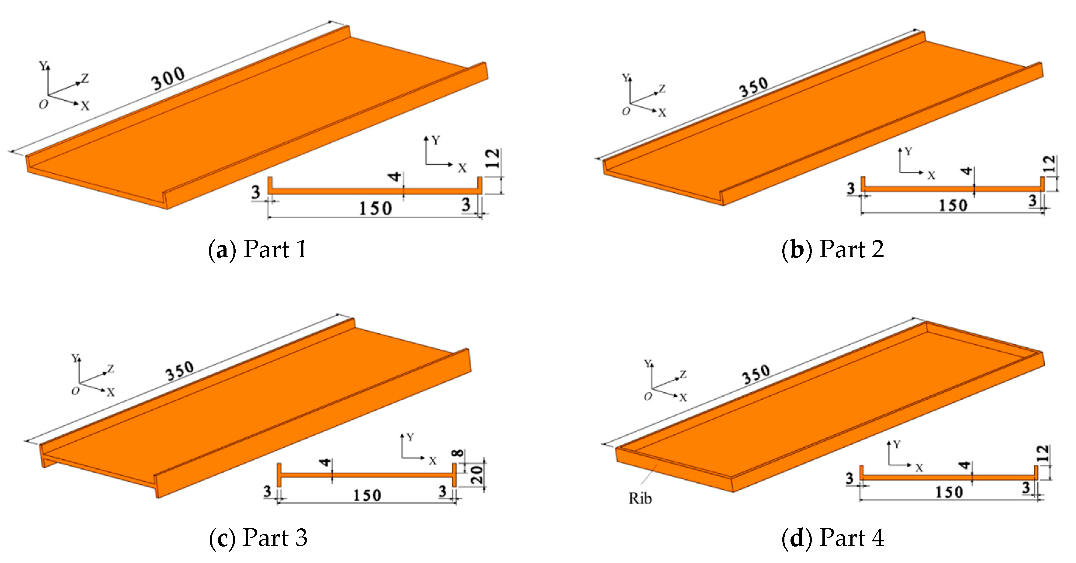
Figure 4.
Measurement of the initial residual stress.

Figure 5.
The initial residual stress distribution. (a) 20 mm. (b) 30 mm.
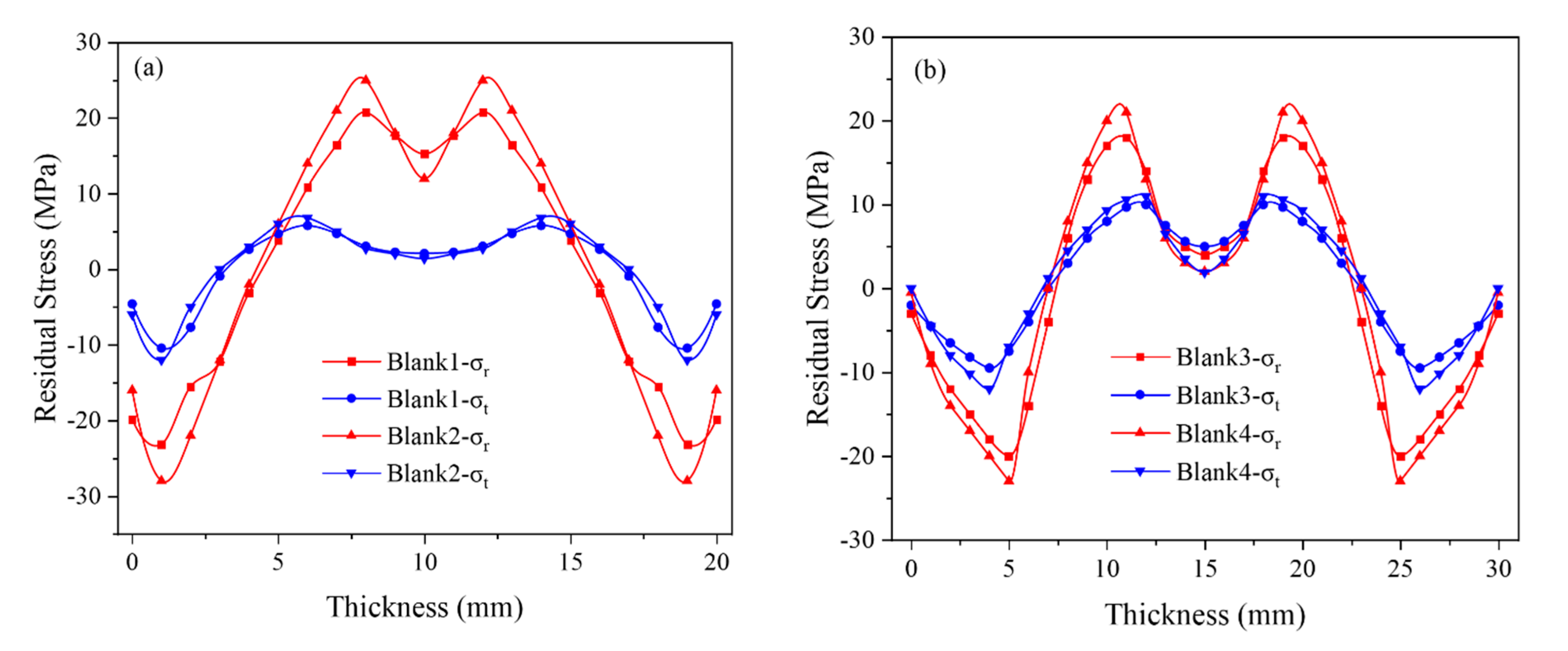
Figure 6.
Initial residual stress inside the blank of blank 1. (a) The FE model of Blank 3 (unit = MPa). (b) The simulation results (part 2, blank 3, A2 = 7 mm, unit = mm).
Figure 6.
Initial residual stress inside the blank of blank 1. (a) The FE model of Blank 3 (unit = MPa). (b) The simulation results (part 2, blank 3, A2 = 7 mm, unit = mm).
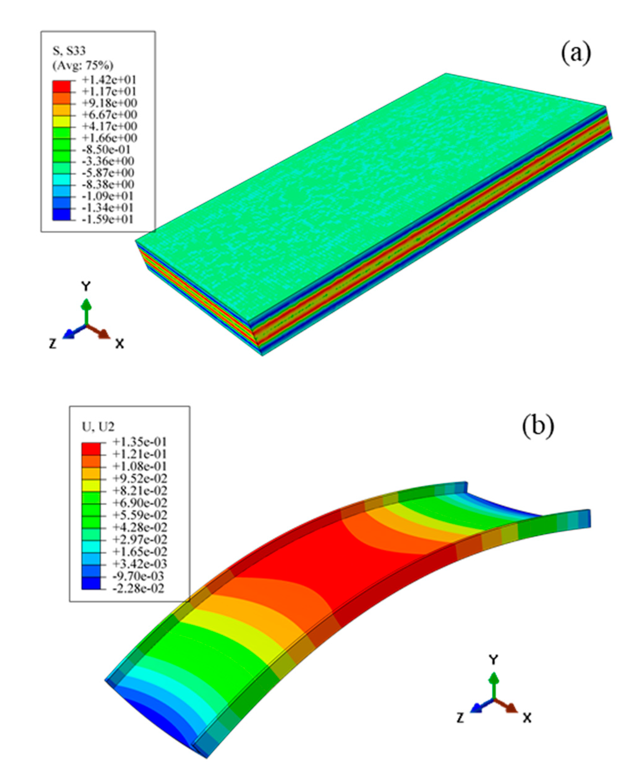
Figure 7.
Experiment and measurement setup. (a) Milling of Part 4. (b) CMM measurement. (c) The measurement points.
Figure 7.
Experiment and measurement setup. (a) Milling of Part 4. (b) CMM measurement. (c) The measurement points.
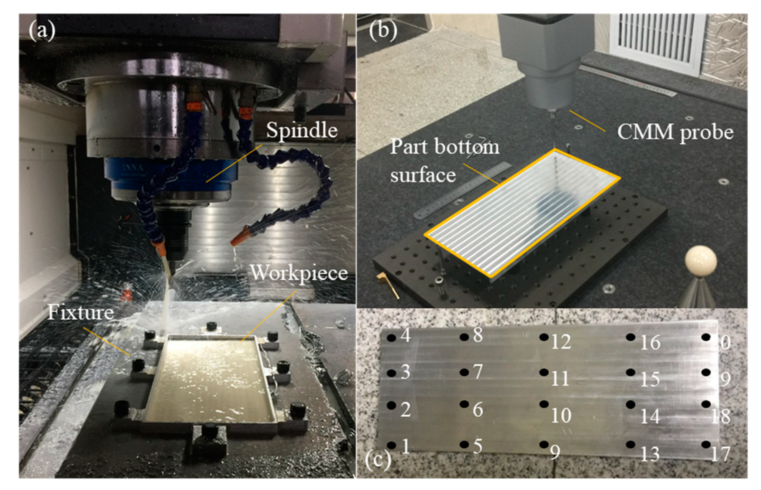
Figure 8.
The final distortion of all the specimens.
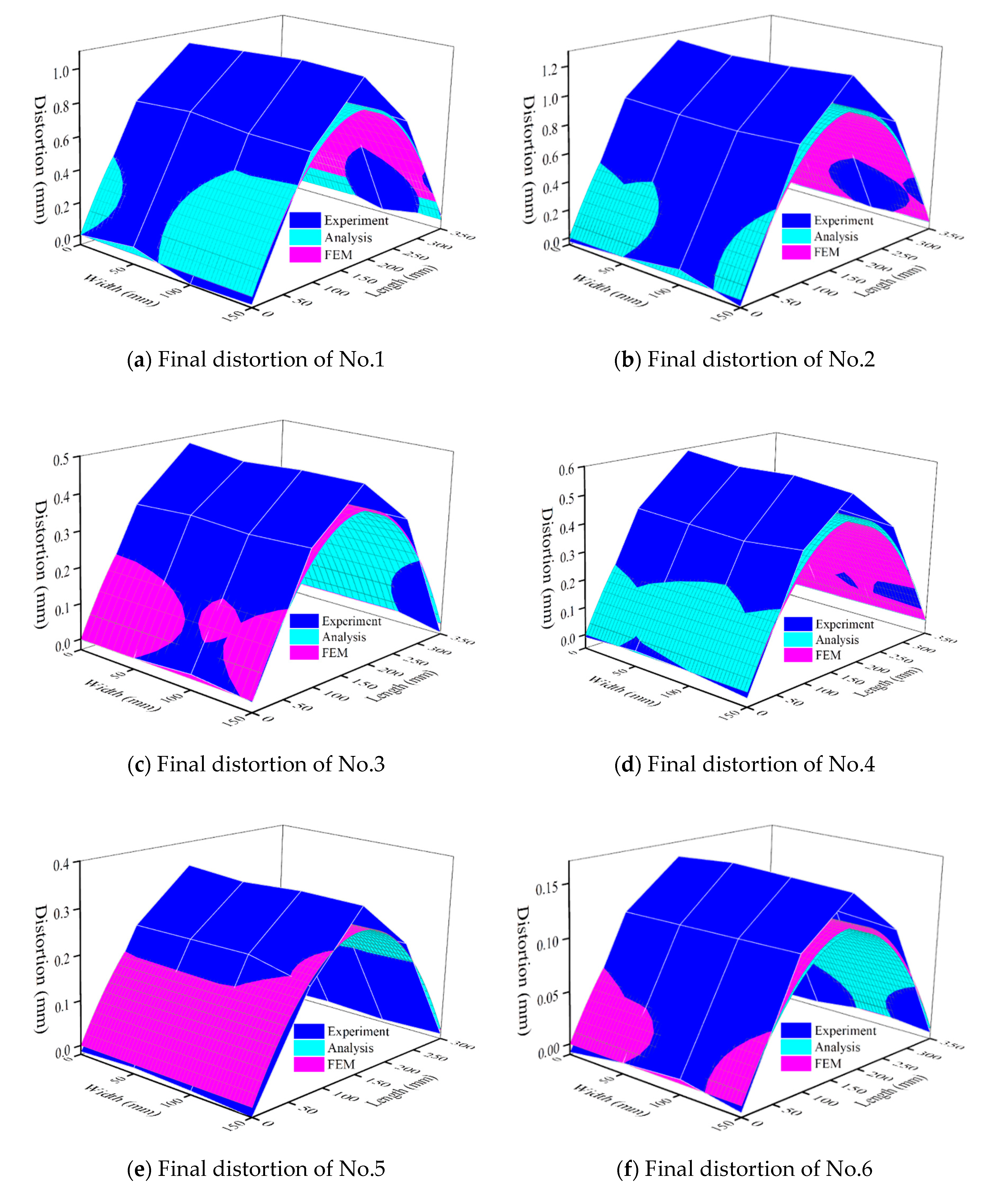
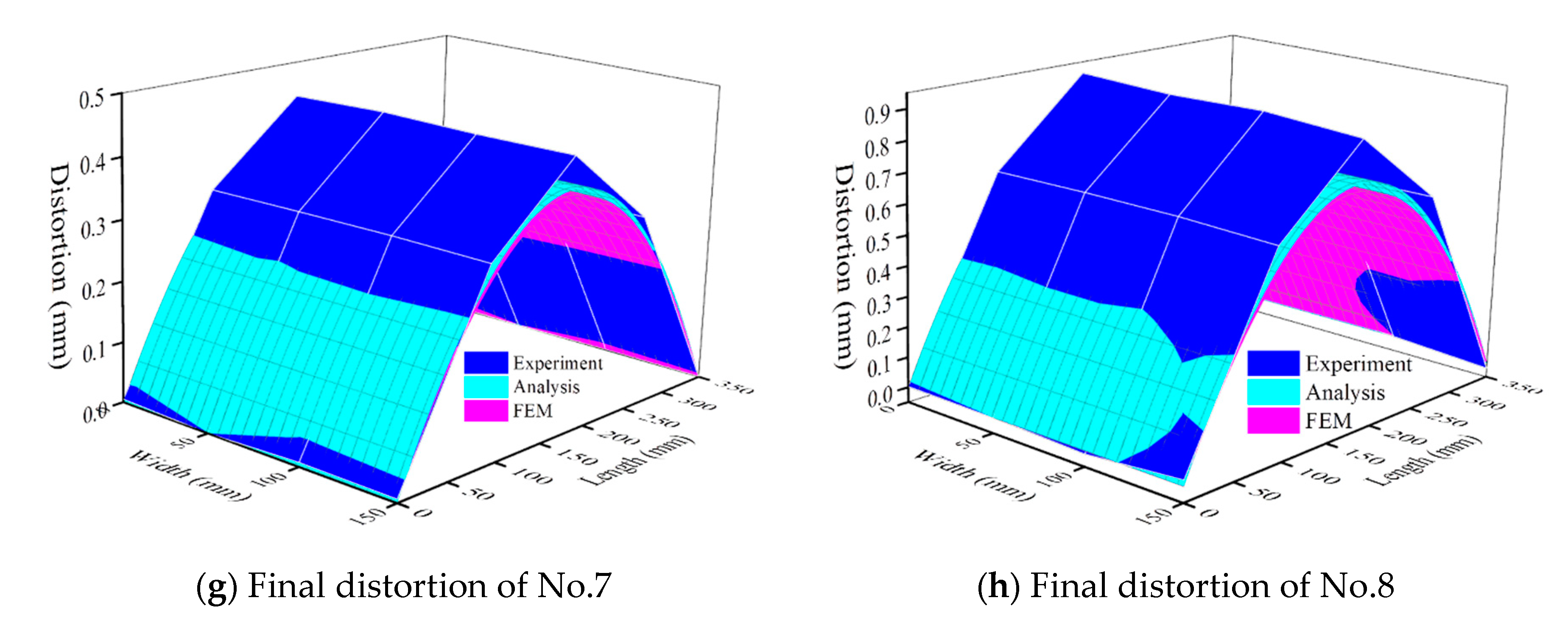
Figure 9.
The maximum relative error value.

Figure 10.
The bending energy vs. final part distortion.
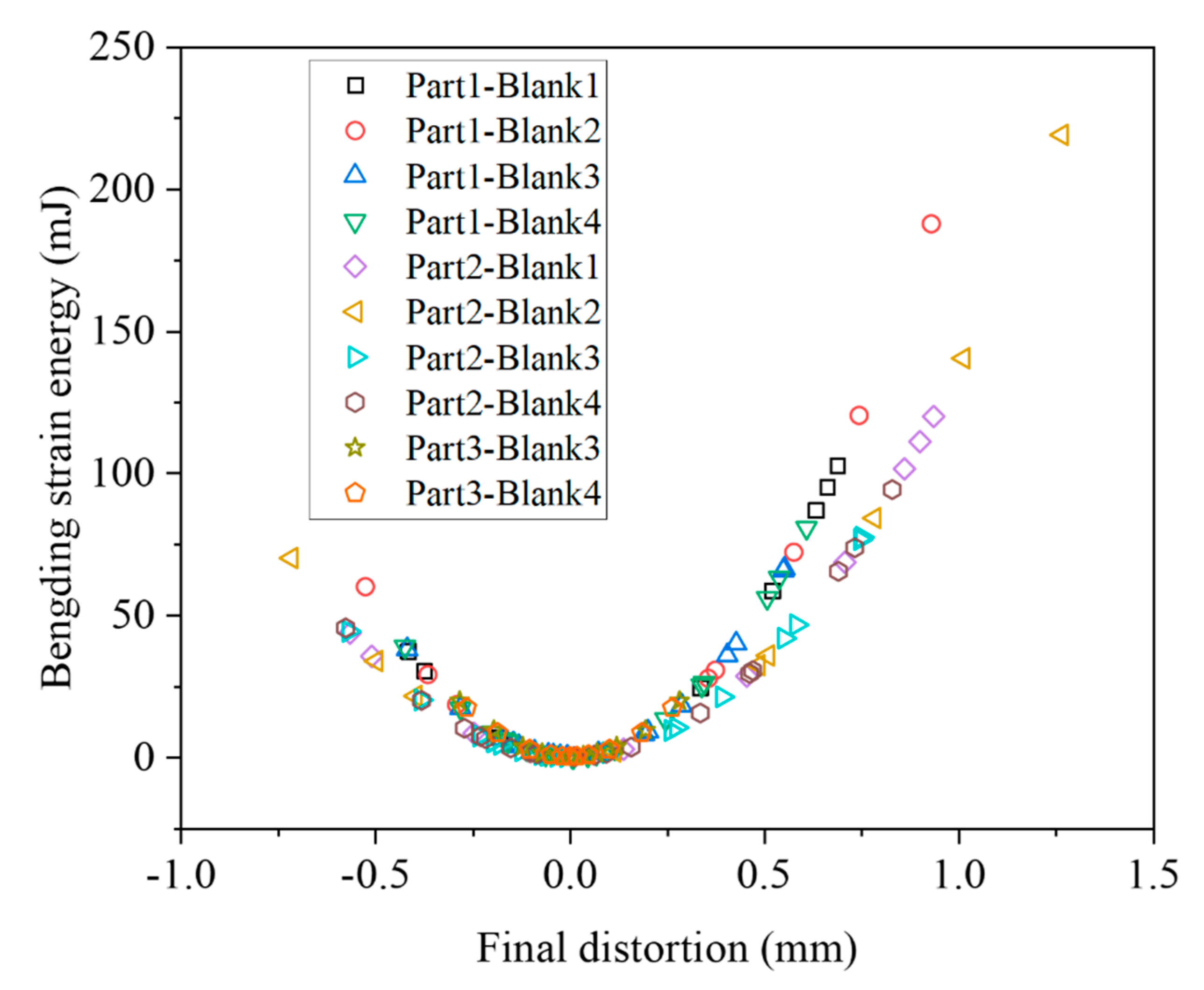
Figure 11.
The distortion of part 1 in different blanks.
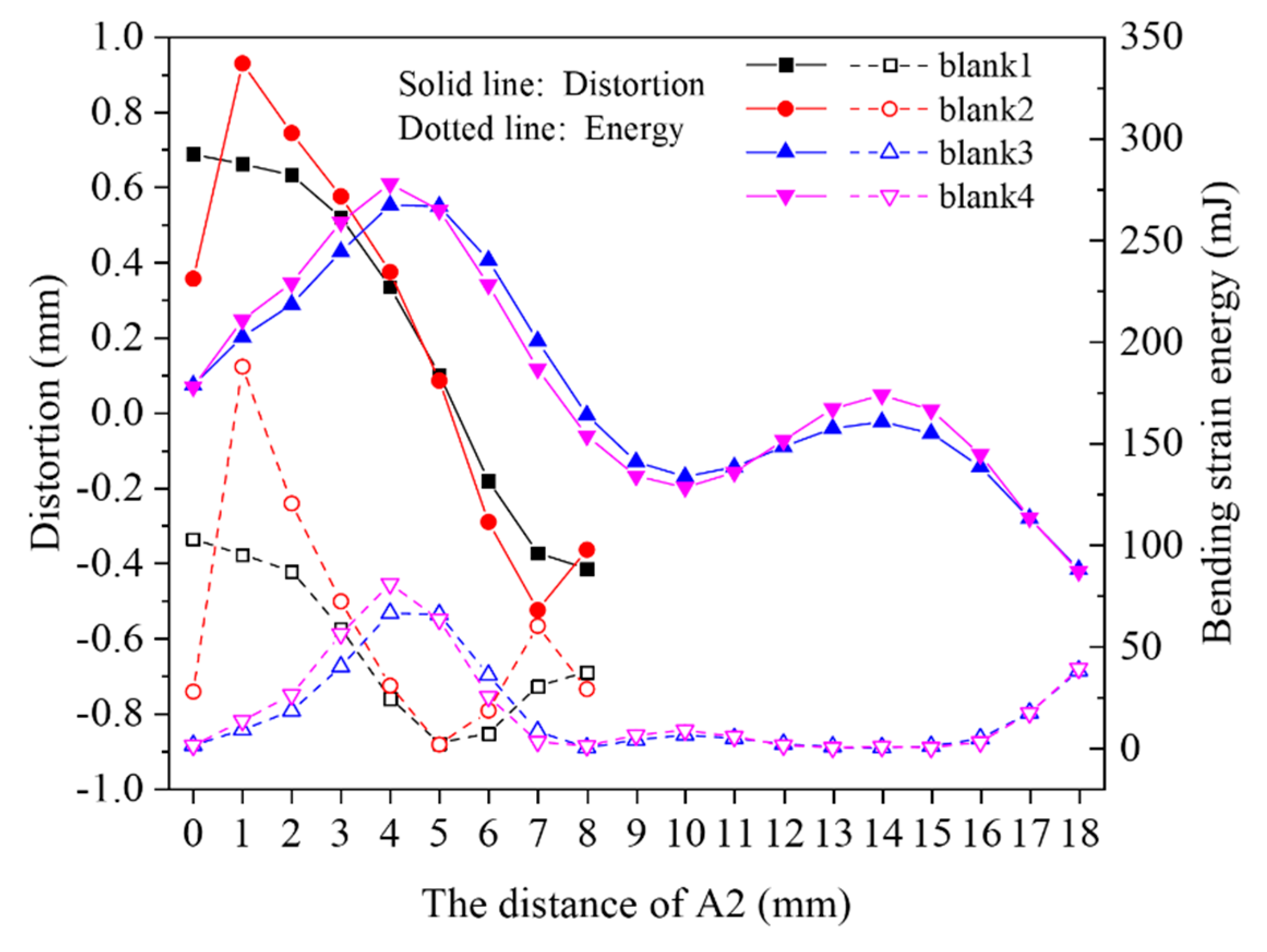
Figure 12.
The distortion difference of part 1 in different blanks.

Figure 13.
Comparison of the distortion of part 2 and part 3.
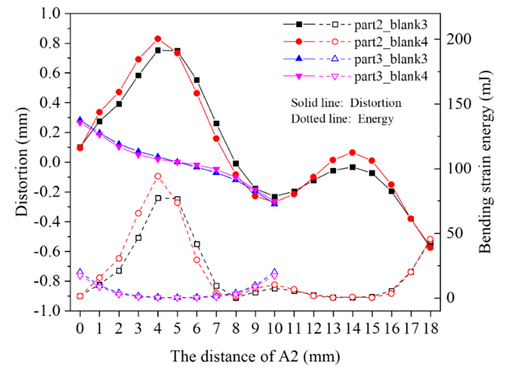
Figure 14.
The bottom distortion difference between part 2 and part 4 in blank 3 (A2 = 2 mm).
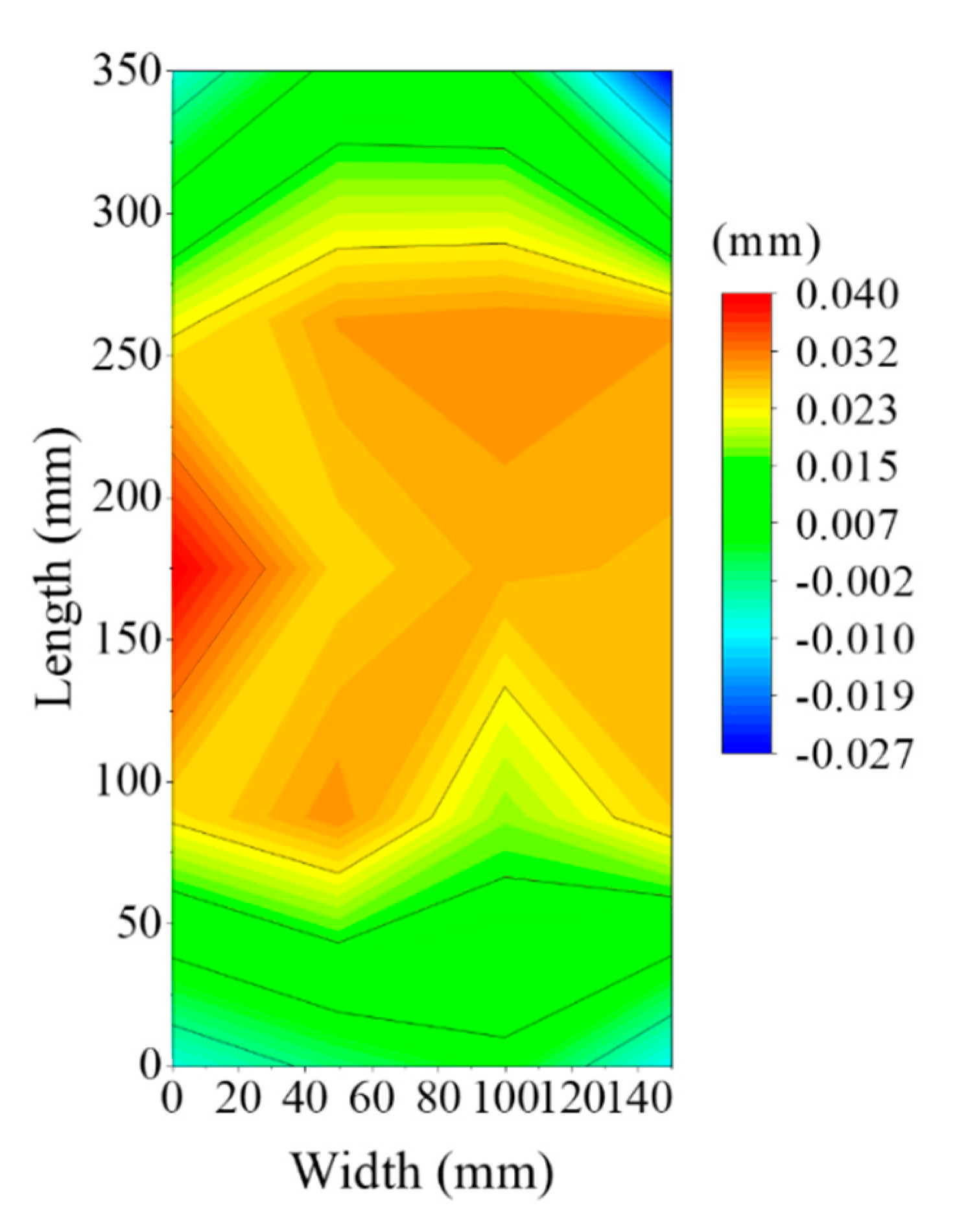
Figure 15.
Comparison of the strain energy.


Table 1.
Mechanical properties of AA6061-T651.
| Elastic Modulus (GPa) | Yield Strength (MPa) | Poisson’s Ratio | Density (kg/m−3) |
|---|---|---|---|
| 68.9 | 240 | 0.33 | 2.75 |
Table 2.
The numerical and experimental machining plans.
| Configuration | Numerical and Experimental Machining Plans | ||
|---|---|---|---|
| Initial Residual Stress Fluctuation | Part Geometry | Part Location | |
| No.1 | Blank 1 | Part 2 | A1 = 35 mm, A2 = 2 mm |
| No.2 | Blank 2 | Part 2 | A1 = 35 mm, A2 = 2 mm |
| No.3 | Blank 3 | Part 2 | A1 = 35 mm, A2 = 2 mm |
| No.4 | Blank 4 | Part 2 | A1 = 35 mm, A2 = 2 mm |
| No.5 | Blank 3 | Part 1 | A1 = 35 mm, A2 = 2 mm |
| No.6 | Blank 3 | Part 3 | A1 = 35 mm, A2 = 2 mm |
| No.7 | Blank 3 | Part 4 | A1 = 35 mm, A2 = 2 mm |
| No.8 | Blank 3 | Part 2 | A1 = 35 mm, A2 = 4 mm |
Table 3.
The theoretical minimum distortion and the corresponding part position.
| Part | Blank | The Minimum Distortion Value (mm) | The Corresponding Part Location A2 (mm) |
|---|---|---|---|
| Part 2 | Blank 1 | 0.14 | 5 |
| Blank 2 | 0.12 | 5 | |
| Blank 3 | −0.01 | 8 | |
| Blank 4 | 0.01 | 15 | |
| Part 3 | Blank 3 | 0 | 5 |
| Blank 4 | 0 | 5 |
Publisher’s Note: MDPI stays neutral with regard to jurisdictional claims in published maps and institutional affiliations. |
© 2020 by the authors. Licensee MDPI, Basel, Switzerland. This article is an open access article distributed under the terms and conditions of the Creative Commons Attribution (CC BY) license (http://creativecommons.org/licenses/by/4.0/).
Share and Cite
MDPI and ACS Style
Fan, L.; Tian, H.; Li, L.; Yang, Y.; Zhou, N.; He, N. Machining Distortion Minimization of Monolithic Aircraft Parts Based on the Energy Principle. Metals 2020, 10, 1586. https://doi.org/10.3390/met10121586
AMA Style
Fan L, Tian H, Li L, Yang Y, Zhou N, He N. Machining Distortion Minimization of Monolithic Aircraft Parts Based on the Energy Principle. Metals. 2020; 10(12):1586. https://doi.org/10.3390/met10121586
Chicago/Turabian StyleFan, Longxin, Hui Tian, Liang Li, Yinfei Yang, Nenggan Zhou, and Ning He. 2020. "Machining Distortion Minimization of Monolithic Aircraft Parts Based on the Energy Principle" Metals 10, no. 12: 1586. https://doi.org/10.3390/met10121586
Note that from the first issue of 2016, this journal uses article numbers instead of page numbers. See further details here.