Article

An Investigation of the Uniaxial Compressive Strength of a Cemented Hydraulic Backfill Made of Alluvial Sand

1
School of Civil and Resources Engineering, University of Science and Technology Beijing, 30 Xueyuan Road, Haidian District, Beijing 100083, China
2
Department of Civil, Geological and Mining Engineering, École Polytechnique de Montréal, C.P. 6079 Succursale Centre-Ville, Montreal, QC H3C 3A7, Canada
3
Beijing General Research Institute of Mining and Metallurgy, Building 23, Zone 18 of ABP, No. 188, South 4th Ring Road West, Beijing 100160, China
4
Mining TEC (Technical Excellence Centre), Vale Base Metals, Brownfield Exploration, 337 Power Street, Copper Cliff, Sudbury, ON P0M 1N0, Canada
5
Mines Geology & Technical Services, Vale Canada Limited, Ontario Operations, Vale Canada Limited, 18 Rink Street, Copper Cliff, Sudbury, ON P0M 1N0, Canada
*
Author to whom correspondence should be addressed.
Minerals 2017, 7(1), 4; https://doi.org/10.3390/min7010004
Submission received: 10 August 2016 / Revised: 15 December 2016 / Accepted: 21 December 2016 / Published: 3 January 2017

Abstract

:
Backfill is commonly used in underground mines. The quality control of the backfill is a key step to ensure it meets the designed strength requirement. This is done through sample collection from the underground environment, followed by uniaxial compression tests to obtain the Uniaxial Compressive Strength (UCS) in the laboratory. When the cylindrical cemented backfill samples are axially loaded to failure, several failure modes can be observed and mainly classified into diagonal shear failure and axial split failure. To date, the UCS obtained by these two failure modes are considered to be the same with no distinction between them. In this paper, an analysis of the UCS results obtained on a cemented hydraulic backfill made of alluvial sand at a Canadian underground mine over the course of more than three years is presented. The results show that the UCS values obtained by diagonal shear failure are generally higher than those obtained by axial split failure for samples with the same recipe and curing time. This highlights the importance of making a distinction between the UCS values obtained by the two different modes of failure. Their difference in failure mechanism is explained. Further investigations on the sources of the data dispersion tend to indicate that the UCS obtained by laboratory tests following the current practice may not be representative of the in-situ strength distribution in the underground stopes due to segregation in cemented hydraulic backfill.

1. Introduction

Backfill is commonly used in underground mines to improve ground stability, reduce ore dilution, increase ore recovery, and improve efficiency of the ventilation system [1]. In most cases, binder is added and blended with particulate material to form a cemented backfill. The particulate material can be sand, tailings, or crushed waste rock while the binder can be a cement, slag, fly ash, or a mixture of them. Water is needed for the hydration of the binder material.
To ensure safe production and successful application of the backfill, the required strength of the cemented backfill must be adequately evaluated. This strength can be calculated through the use of analytical solutions proposed by Mitchell et al. (1982) [2], Li and Aubertin (2012, 2014) [3,4], Li (2014a, 2014b) [5,6], and Liu et al. (2016) [7] for vertical cemented backfill exposures. For horizontal cemented backfill exposures, analytical solutions have been proposed by Mitchell (1991) [8], but are seldom used due to the indetermination of several parameters [9,10,11]. An empirical chart proposed by Stones (1993) [12] is commonly used in this scenario [13].
Once the required strength of cemented backfill has been evaluated, the optimal recipe to meet the required fill strength is commonly determined through an evaluation of the UCS of different recipes (mixtures). Knowing that the strength of cemented backfill depends on several influencing factors that include binder content, solid (tailings or/and sand) percentage, water content, and curing time, determination of an optimal recipe may depend on the target (shorter curing time versus lower cement consumption) and require a lot of laboratory tests [14,15,16,17,18,19,20,21,22,23].
When a cylindrical sample of cemented backfill is axially loaded to failure, several modes of failure can be observed, including diagonal shear (Figure 1a) [24,25,26,27], ‘X’ cone-shear (Figure 1b) [28,29], single (or columnar) split (Figure 1c) [24,26,29,30,31,32], and ‘Y’ cone-split (Figure 1d) [24,27,32]. Similar failure modes have equally been observed in uniaxial compression tests with concrete or cemented soils [33,34]. The diagonal shear (Figure 1a) and ‘X’ cone-shear (Figure 1b) failure modes can be classified as failure through diagonal shear. The single split (Figure 1c) and ‘Y’ cone-split (Figure 1d) are classified as failure by axial splitting. The former means that the sample is submitted to a state of compression and fails due to the lack of sufficient compressive strength (or shear strength along the critical planes). The latter implies that the sample is submitted to a stress state of tension along the vertical plane and fails due to the lack of sufficient tensile strength. As geomaterials usually have a higher compressive strength than tensile strength [35,36,37,38,39,40,41,42,43], it can be expected that the UCSes obtained by axial split failure are lower than those obtained by diagonal shear failure.
Despite these results being commonly observed in geomaterials (rocks, concrete, etc.), the distinction between the UCS obtained by axial split and diagonal shear failures of cemented backfill samples has never been made. All the UCS values are considered in the same way and used together for calculating the average value of the UCS for the cemented backfill. In this paper, the UCS of a cemented hydraulic backfill made of alluvial sand will be examined by considering the associated modes of failure.

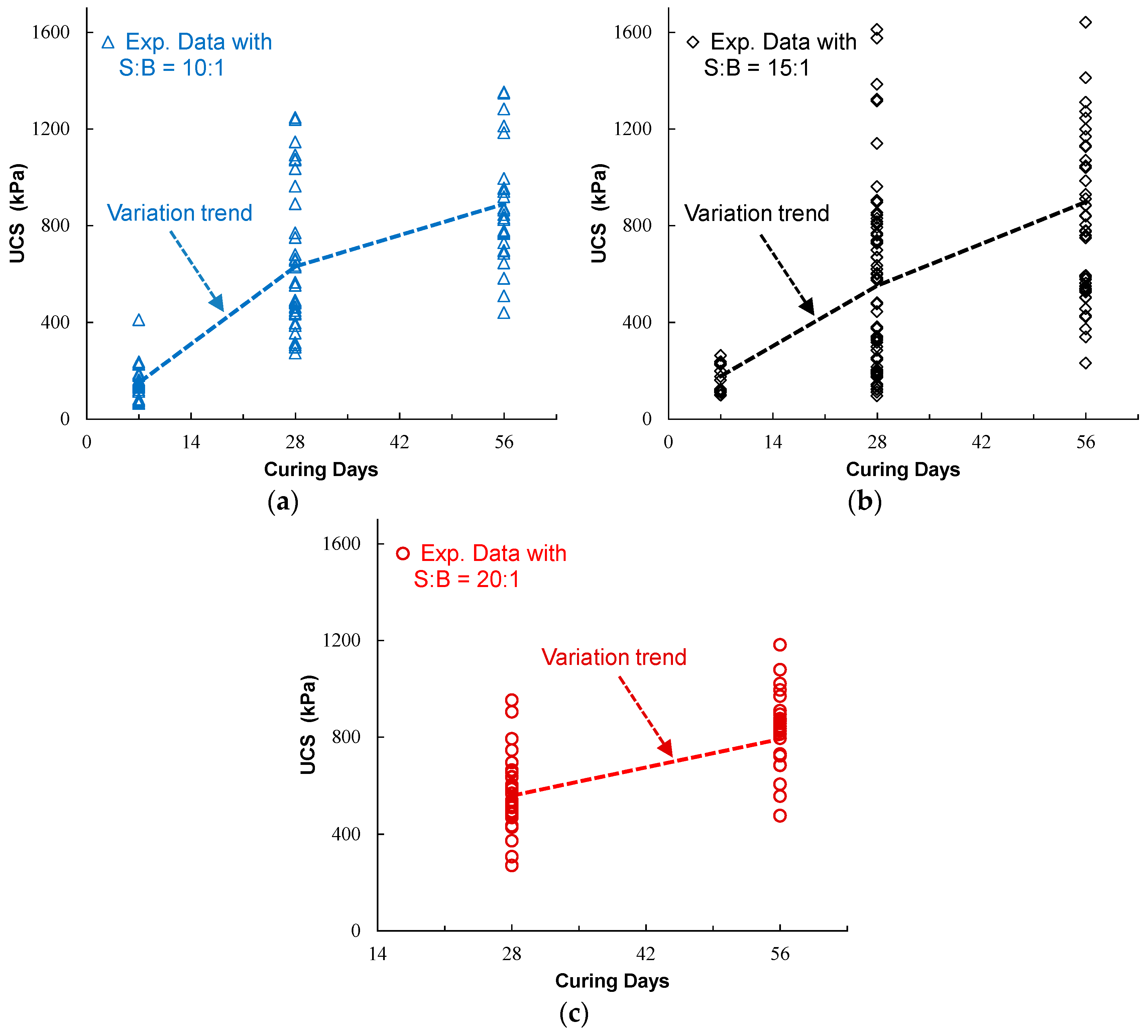
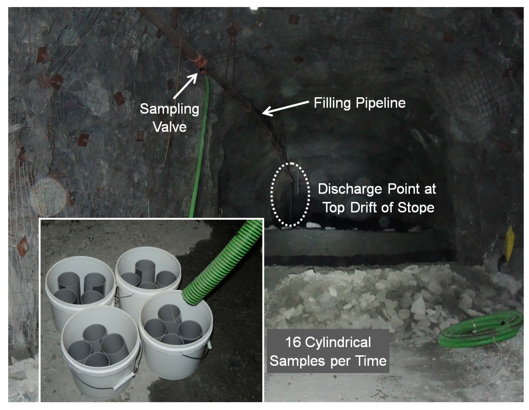
2. Tested Materials and Experimental Results

As part of the backfill quality control program at Vale’s Totten Mine, underground sampling and the measurement of UCS have been completed. Since 2013, cemented hydraulic backfill made of alluvial sand has been sampled and cured underground in conjunction with backfilled stopes. When the targeted curing time arrives, samples are brought to the surface and sent to a laboratory for uniaxial compression tests. The failure modes of each sample have been tracked along with the associated UCS values.
Cemented hydraulic backfill at Totten Mine is composed of alluvial sand (aggregate), binder, water, and flocculant at a rate of 20 grams per ton. The sand is extracted from a pit near the mine site. The use of alluvial sand in the case of Totten Mine is required as the site is located far from the mill location.
Table 1 illustrates the main physical properties of the normal stored alluvial sand used for the preparation of Totten Mine backfill. The detailed particle size distribution (PSD) of the alluvial sand used at Totten Mine is shown in Figure 2, along with the fine and coarse tolerance limits for sand quality control. The PSD curve represents the sand received by the mine for the preparation of their cemented hydraulic backfill. Based on the unified soil classification system, the sand in the normal case is identified as SW-SM (well-graded silty sand; ASTM Standard D2487 2011) [44].
The mineral analysis shows that the sand is constituted of quartz diorite and olivine diabase and mainly made of nonmetallic and metallic oxides (silicon dioxide, aluminum oxide, ferric oxide, etc.) with minimal sulphide and phosphide.
The binder used for the backfill is made of 70% slag and 30% Ordinary Portland cement (called “70-30 NewCem GU”). The chemical compositions of the waste smelting slag are listed in Table 2, and the characteristic parameters of the final mixed “70-30 NewCem GU” binder are summarized in Table 3.
Water used for the preparation of the cemented hydraulic backfill comes from the water processing plant at Totten Mine, which is fed partly by water pumped from different underground levels and nearby ponds.
The cemented hydraulic backfill consisting of fully blended alluvial sand and “70-30 NewCem GU” binder with a pulp density of 72% solids by weight is delivered to underground stopes through a borehole and pipelines. Three sand to binder ratios are utilized, depending on the backfill function: 10:1 for the plug and cap pours, and 15:1 or 20:1 for the main body of the backfilled stopes.
Backfill sampling was carried out at the overcut of the stope being filled. Molds made of PVC pipes 10 cm in diameter and 20 cm in height were put in buckets, which were 10 cm higher than the PVC pipe molds, as shown in Figure 3. When the backfill slurry reaches full density, the valve assembly connected with the pipeline was opened to fill the buckets and the PVC pipe molds. Four buckets were filled separately at controlled intervals to test the uniformity of the backfill and to obtain samples that are representative of the backfill poured in the stope. The backfill samples in the buckets were covered and kept in place for curing. At a scheduled curing time (7, 28, and 56 days), buckets were transported to the surface and the samples were tested in a geotechnical laboratory. Efforts are made to keep the samples moist to ensure they do not dry out.
In the laboratory, the backfill samples were prepared before being subjected to unconfined compression tests following the ASTM standard for uniaxial compressive strength of cylindrical concrete specimens (ASTM Standard C39/C39M 2012) [45]. The preparation included the cutting and grinding of the samples to obtain the final dimensions, flat and smooth end surfaces. The UCS values and failure modes were recorded.
Figure 4 shows the UCS results with different sand to binder ratios and curing days obtained from 2013 to 2015. A total of 330 UCS test results have been obtained and analyzed in this data. The UCS results are very dispersed and the range of data will be analyzed in the following section.

3. Analysis of the Experimental Results

3.1. Correction Due to Shape Effect

In uniaxial compression testing, the strength of cylindrical samples increases as the height to diameter ratio decreases [46]. This ratio must have a minimum value of 2 to eliminate end effects for rock [47], concrete [45], and soil [48]. The results shown in Figure 4 were based on cylindrical samples whose height to diameter ratios were in some cases less than 2. The UCS values obtained with the samples having a height to diameter ratio less than 2 need to be subject to correction factors summarized in Table 4 (ASTM Standard C39/C39M 2012) [45]. Figure 5 shows the UCS results after the correction due to the shape effect. The results remain very dispersed after the correction.

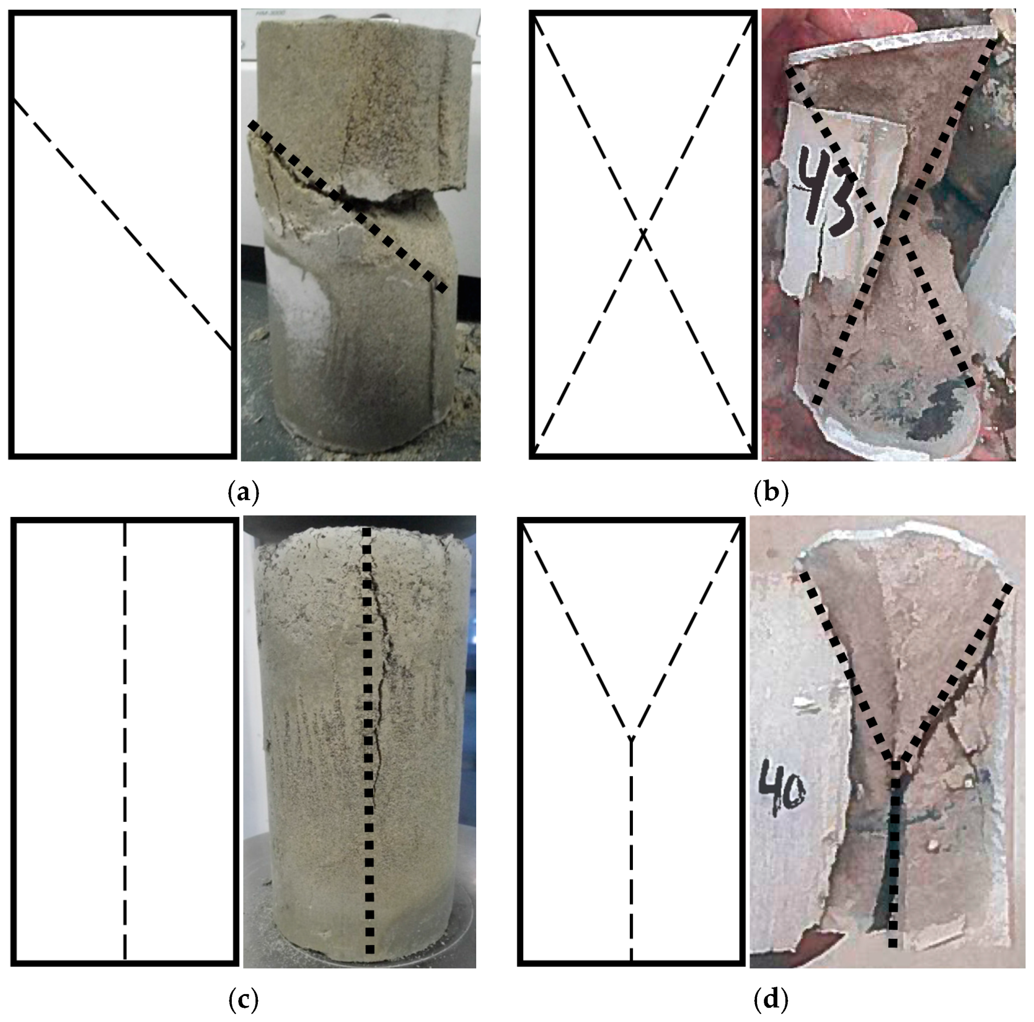
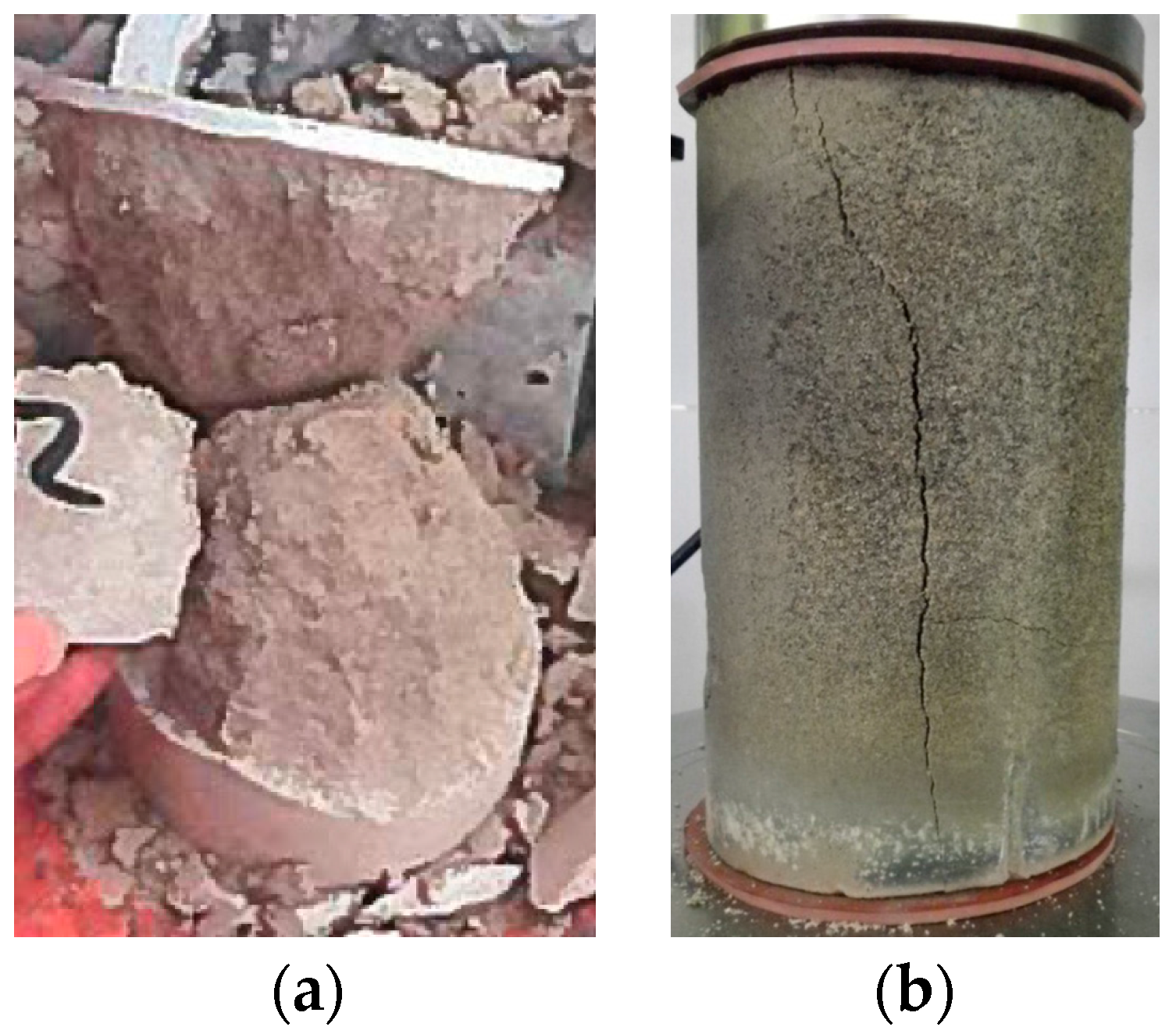
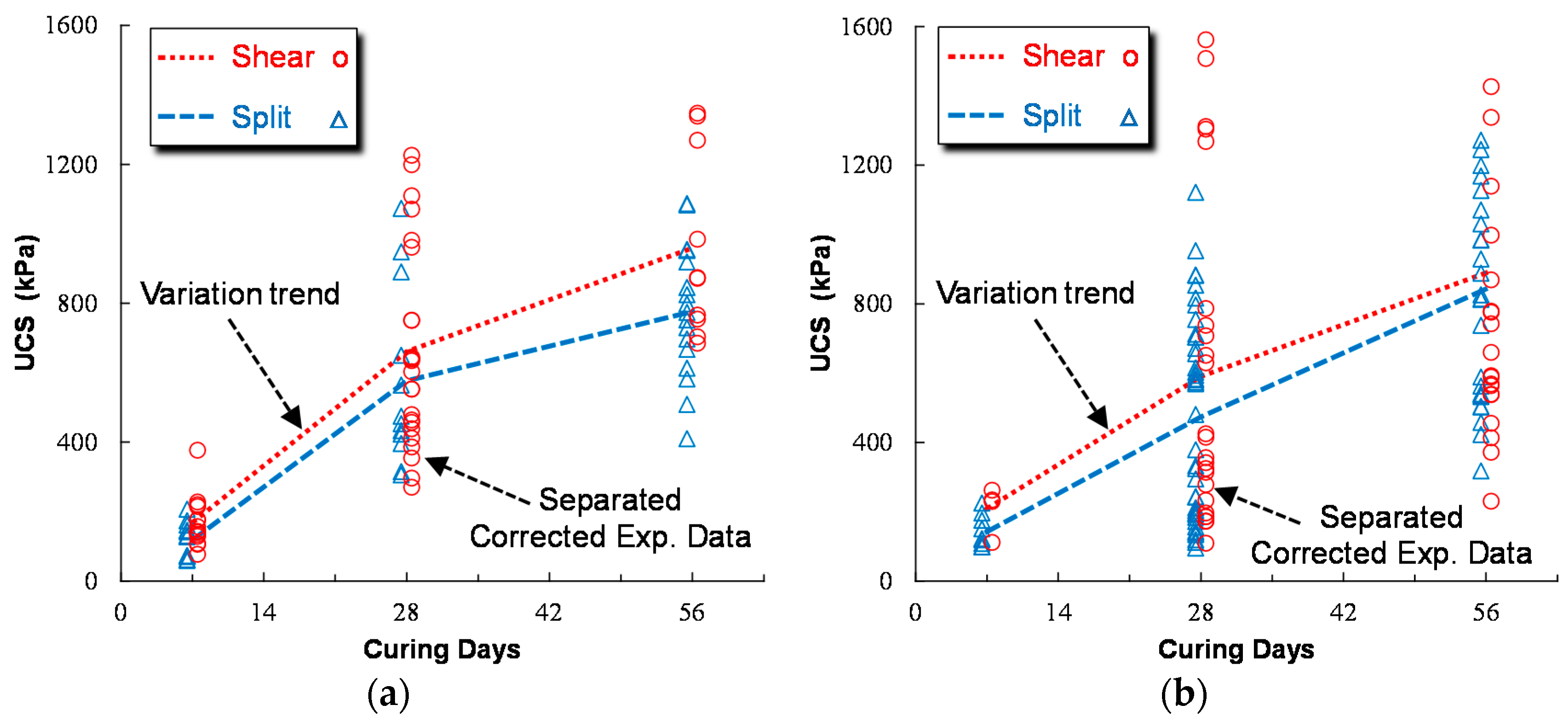
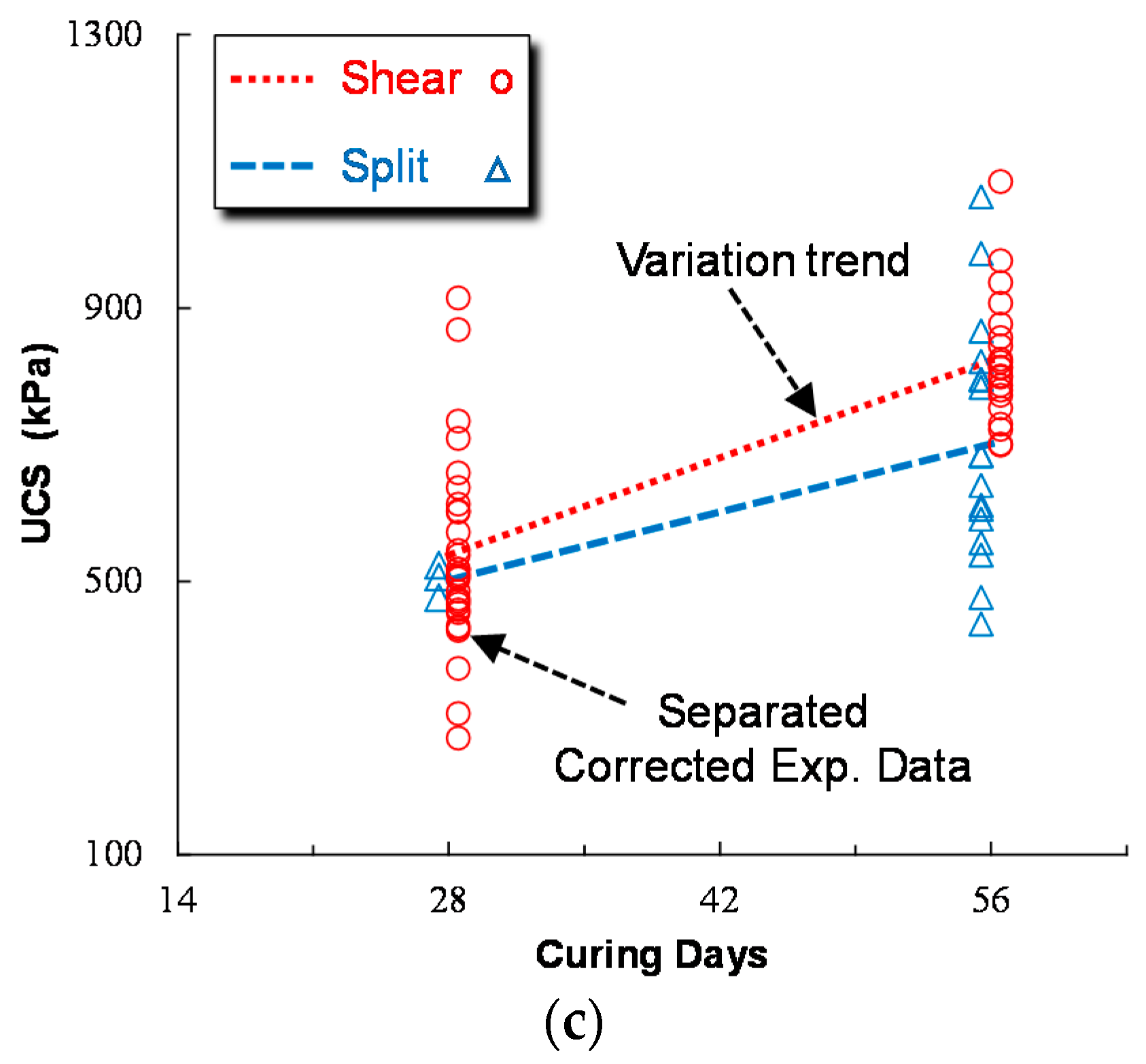
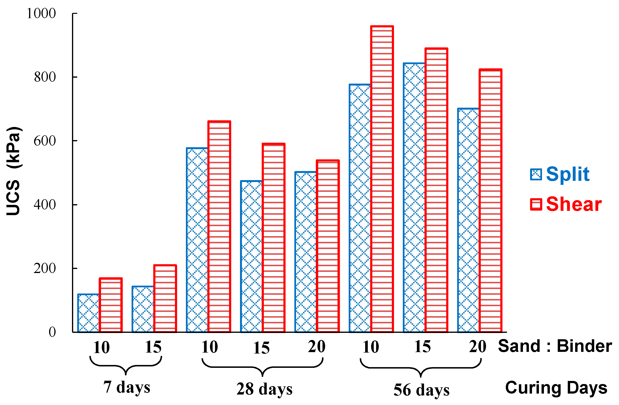
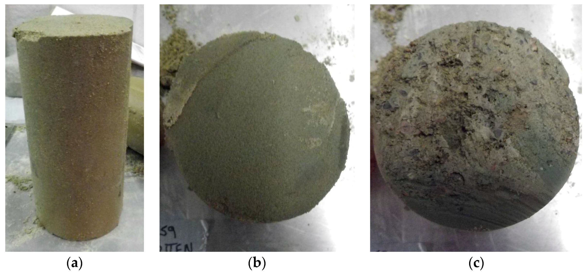
3.2. UCS Values Accounting for the Failure Modes

Figure 6 shows that the cylindrical samples of the cemented hydraulic backfill submitted to uniaxial compression test conditions can show a failure behavior by diagonal shear (Figure 6a) or axial split (Figure 6b). The experimental results shown in Figure 4 and Figure 5 were obtained with cylindrical samples loaded to failure without making any distinction between the associated failure modes. As mentioned earlier, failure through diagonal shear results from a compression stress state exceeding the shear strength along the diagonal critical plane, while failure by axial split is induced by a tension stress state exceeding the tensile strength along the vertical plane. As geomaterials usually have a higher strength in compression than in tension, it is realistic to distinguish the UCS values obtained by diagonal shear or axial split failure. The experimental results of corrected UCS values shown in Figure 5 will be presented with a distinction made for the type of failure mode.
The experimental results shown in Figure 5 are modified and presented in Figure 7 with the identification of diagonal shear and axial split failure modes. Even though the dispersion of the experimental results remains very large, one can see higher average UCS values with the diagonal shear failure mode for a given sand to binder ratio at the same curing time. The difference between the UCS obtained with diagonal shear and with axial split can be seen in Figure 8, where the average UCS values of cemented hydraulic backfill samples in diagonal shear and axial split failure modes at different curing times are illustrated for various sand to binder ratios.
These results indicate that the strength of the cemented hydraulic backfill made of alluvial sand could be underestimated if the tested UCS values are treated without distinguishing the diagonal shear and axial split failure modes. Based on the experimental data shown in Figure 8, one sees that the ratio of the uniaxial compressive strength by axial split (UCSsplit) to that by diagonal shear (UCSshear) may vary from 0.65 to 0.90, with an average value of about 0.80.

4. Discussion

The appearance and the mechanism of different failure modes observed on cemented backfill samples under uniaxial compression has been explained by different researchers [46,49,50,51]. These works can be useful to help understand the failure modes in some special cases, but more work is needed to fully understand the mechanisms of different modes of failure.
Despite the correction due to the shape effect and the distinction of diagonal shear and axial split failure modes, the results shown in Figure 7 remain very dispersed. This dispersion may be attributed to other factors that are discussed below.

4.1. Effect of Ends Flatness in Cylindrical Samples

According to the ASTM standard C39/C39M (2012) [45] for UCS tests on concrete, the two ends of the cylindrical samples should be cut and ground to a flat and smooth state before completing uniaxial compression tests. In practice with cemented hydraulic backfill, this requirement is difficult to realize, as shown in Figure 9. As the mine backfill usually has a low binder content, the cylindrical samples usually have a lower strength and piece detachment (Figure 9a) or piece residue (Figure 9b) can result during the sample cutting process. Furthermore, due to its low strength, the hard sand particles can be removed during the cutting and grinding process, leading to cavity and rough ends, as shown in Figure 9c. These rough or even uneven end faces may result in unexpected loading and stress distribution in the tested samples. In extreme cases, the uneven end faces may result in application of an axial load which is non-parallel to the axis of the cylindrical samples. In all cases, these errors during the test procedure can increase and even amplify the dispersion of the experimental data.

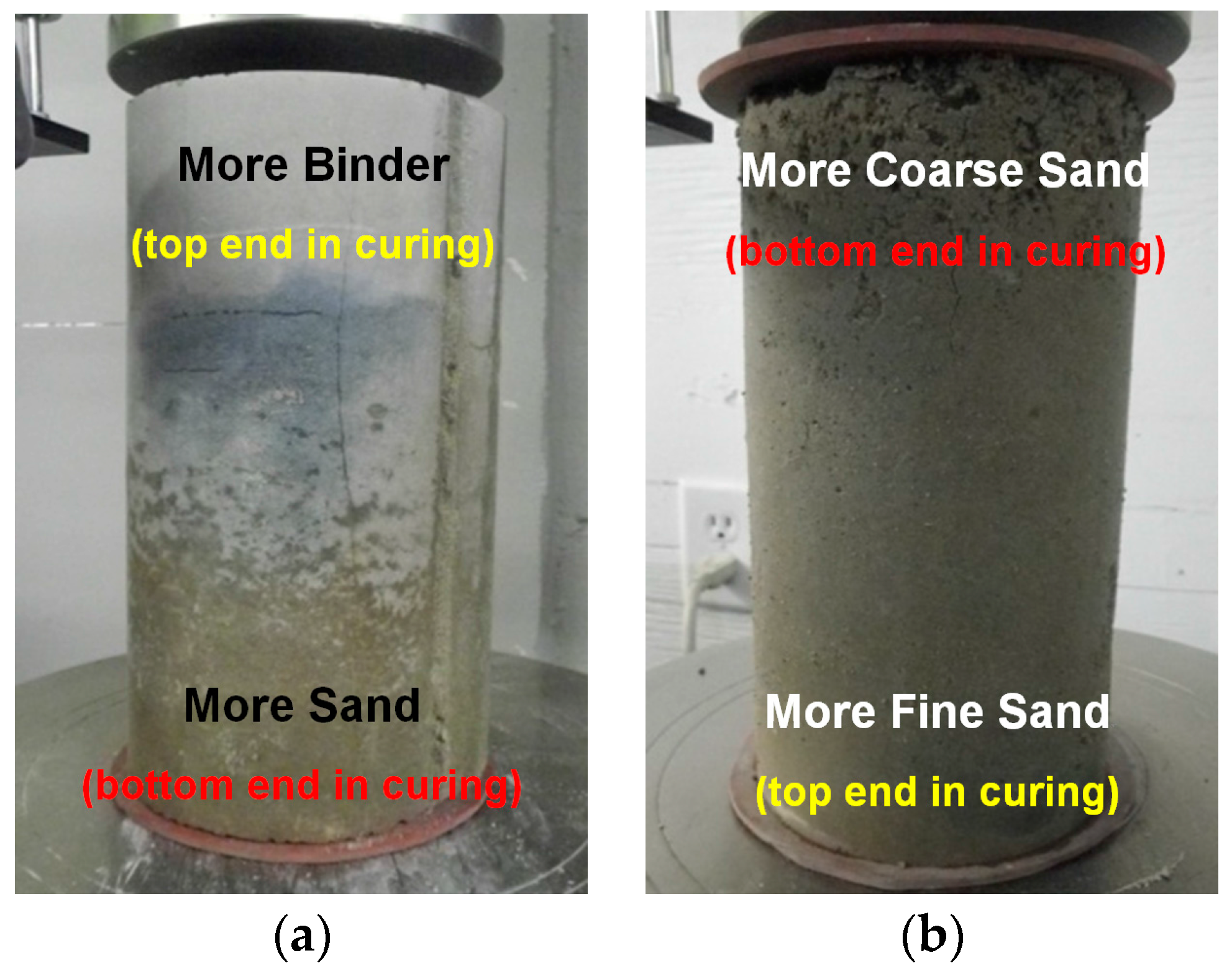
4.2. Effect of Hydraulic Segregation

With hydraulic backfill, segregation is a commonly observed phenomenon, resulting in more sand at the base and more binder at the top of the samples, or more coarse particles at the bottom and more fine particles at the top of the samples, as shown in Figure 10. The former (Figure 10a) is associated with the segregation of binder and sand and the latter (Figure 10b) with the segregation of coarse and fine sand particles. In all cases, segregation leads to different physical and mechanical properties from the top to the bottom of the samples. As the segregation is closely related to the particle size distribution, which may change from time to time and place to place (Figure 2), it is clear that the dispersion shown in Figure 4 and Figure 5 can partly be attributed to the segregation, but this factor is difficult to quantify.
For a given backfill, the strength variation with fill layers has been investigated by Cao et al. (2015) [29]. Their work can be useful to guide the backfilling procedure to minimize the effect of segregation. Alternatively, the segregation can be reduced or minimized by increasing the slurry density, adding more flocculant in the backfill, or ultimately changing to paste backfill. Before any major change, a more pertinent question is if the experimental results, which were obtained in laboratory tests using samples collected at the stope overcut, represent the true strength distribution across the whole height of the stopes due to segregation. Future work is needed to clarify this aspect.

4.3. Particle Size Distribution and Binder Content

The influence of the particle size distribution on the experimental results has been partly discussed in Section 4.2 in relation to segregation.
Figure 8 shows that the UCS values of the cemented hydraulic backfill samples with a sand to binder ratio of 10:1 at a curing time of seven days with the shear failure mode is somewhat smaller than those of the samples with a sand to binder ratio of 15:1. A similar trend has been observed for the samples with sand to binder ratios of 10:1 and 15:1 at a curing time of seven days with the split failure mode. These results suggest that additional binder in the backfill provides little strength gain at the lower seven-day curing time. More work is needed to understand if this is a general trend. Nevertheless, Figure 8 suggests that cemented hydraulic backfill is stronger with higher binder content when the curing time reaches 28 and 56 days, respectively.

5. Conclusions

As part of the quality control on the cemented hydraulic backfill made of alluvial sand, samples have been collected and cured underground in field conditions. At a targeted curing time, the samples were taken to the surface and sent to a geotechnical laboratory for uniaxial compression testing. The analyses of the uniaxial compressive strength results obtained for a three year period lead to the following conclusions:
The uniaxial compressive strengths obtained by axially loading cylindrical samples to failure by shear (UCSshear) are generally higher than those obtained by loading the samples to failure by split (UCSsplit). These results suggest that it is necessary to distinguish the uniaxial compressive strength obtained by shear from split failure modes. The uniaxial compressive strength of the cemented backfill can be underestimated by samples axially loaded to failure by split. These conclusions drawn from experimental tests on cemented hydraulic backfill made of alluvial sand may be valid for other types of cemented backfill like paste backfill. More work is needed to confirm this hypothesis. For the cemented hydraulic backfill made of alluvial sand, the ratio between the uniaxial compressive strength by split (UCSsplit) and that by shear (UCSshear) can vary between 0.65 and 0.90, with an average value of about 0.80.
The above conclusion does not mean that split failure is considered as a legitimate failure mode. It is well known that the failure of homogeneous geomaterials under uniaxial compressions should be cone shear failure. Split failure observed in many experimental tests is mostly of a random nature and caused by imperfections in sample preparation or in loading. In such cases, the test results are mostly erroneous and should not be used for backfill design.
Care is needed in sample preparation to ensure that the samples meet the pertinent standard for UCS testing. The cutting and grinding of samples to ensure flat and smooth end faces is a particularly sensitive item.
Segregation is a commonly observed phenomenon in cemented hydraulic backfill that may significantly contribute to the large dispersion of the UCS data obtained by laboratory tests. More work is needed to fully understand the variation of the strength with segregation. Alternatively, the segregation can be minimized by increasing the slurry density, adding more flocculant in the backfill, changing pouring practice such as continuous pouring or ultimately changing the hydraulic backfill to paste backfill.
The segregation of the cemented hydraulic backfill observed with small samples tends to indicate that segregation can also take place in the stopes filled with the same backfill. More work is needed to understand the in-situ distributions and evolution of the sand particles and binder content in the stope environment.
Future work is required to improve the reliability of the extrapolation procedure by which the strength of the cemented hydraulic backfill in the stopes is represented by the strength obtained in the laboratory from samples collected and cured at a much reduced size (scale).

Acknowledgments

Vale Canada Limited and Totten Mine are gratefully acknowledged for the permission to use and publish their backfill test data. Special thanks to the mine manager and engineers at Totten Mine for their kindness and collaboration during the first author’s internship at the mine. The first author acknowledges the financial support from China Scholarship Council (CSC) under the Grant CSC No. 201406460041. The authors also acknowledge the financial support from the Natural Sciences and Engineering Research Council of Canada (NSERC 402318), Institut de Recherche Robert-Sauvé en Santé et en Sécurité du Travail (IRSST 2013-0029), Fonds de Recherche du Québec-Nature et Technologies (FRQNT 2015-MI-191676), and the industrial partners of the Research Institute on Mines and Environment (RIME UQAT-Polytechnique). Financial support from the National Science and Technology Support Program of China (No. 2013BAB02B02), the Scientific Research Fund of Beijing General Research Institute of Mining and Metallurgy of China (No. YJ201507), and the National Key Research and Development Plan of China (No. 2016YFC0600709) is also gratefully acknowledged. Simon Nickson from Vale Canada Limited and Natasha Carrière from University of British Colombia are gratefully acknowledged for the reading of the manuscript.

Author Contributions

Mike Yao, Farid Malek and David Landry planned the sample collection and testing program of UCS; David Landry collected and archived the experiment results; Guangsheng Liu and Li Li analyzed the experimental data and initiated the writing of the paper; Xiaocong Yang and Lijie Guo help analyze the experimental data. All authors have contributed substantially to the work through extensive and intensive revisions of the paper.

Conflicts of Interest

The authors declare no conflict of interest

References

  1. Darling, P. SME Mining Engineering Handbook, 3rd ed.; Society for Mining, Metallurgy, and Exploration (SME): Englewood, CO, USA, 2011. [Google Scholar]
  2. Mitchell, R.J.; Olsen, R.S.; Smith, J.D. Model studies on cemented tailings used in mine backfill. Can. Geotech. J. 1982, 19, 14–28. [Google Scholar] [CrossRef]
  3. Li, L.; Aubertin, M. A modified solution to assess the required strength of exposed backfill in mine stopes. Can. Geotech. J. 2012, 49, 994–1002. [Google Scholar] [CrossRef]
  4. Li, L.; Aubertin, M. An improved method to assess the required strength of cemented backfill in underground stopes with an open face. Int. J. Min. Sci. Technol. 2014, 24, 549–558. [Google Scholar] [CrossRef]
  5. Li, L. Generalized solution for mining backfill design. Int. J. Geomech. 2014, 14, 1–11. [Google Scholar] [CrossRef]
  6. Li, L. Analytical solution for determining the required strength of a side-exposed mine backfill containing a plug. Can. Geotech. J. 2014, 51, 508–519. [Google Scholar] [CrossRef]
  7. Liu, G.S.; Li, L.; Yang, X.C.; Guo, L.J. Stability analyses of vertically exposed cemented backfill: A revisit to Mitchell’s physical model tests. Int. J. Min. Sci. Technol. 2016, 26, 1135–1144. [Google Scholar] [CrossRef]
  8. Mitchell, R.J. Sill mat evaluation using centrifuge models. Min. Sci. Technol. 1991, 13, 301–313. [Google Scholar] [CrossRef]
  9. Caceres, C.A. Effect of Delayed Backfill on Open Stope Mining Methods. Master’s Thesis, University of British Columbia, Vancouver, BC, Canada, 2005. [Google Scholar]
  10. Donovan, J.; Dawson, J.; Bawden, W.F. David Bell mine underhand cut and fill sill mat test. In Minefill 2007, Proceedings of the 9th International Symposium on Mining with Backfill, Montreal, QC, Canada, 29 April–3 May 2007; Canadian Institute of Mining, Metallurgy and Petroleum (CIM): Westmount, QC, Canada, 2007. [Google Scholar]
  11. Oulbacha, Z. Analyse Numérique de la Stabilité des Piliers-Dalles en Remblai Cimenté: Une Vérification des Modèles de Mitchell [Numerical Analysis on the Stability of Cemented Backfill Sill Mats: Verification on Mitchell Models]. Master’s Thesis, École Polytechnique de Montréal, Montreal, QC, Canada, 2014. [Google Scholar]
  12. Stone, D.M.R. The optimization of mix designs for cemented rockfill. In Minefill 1993; South African Institute of Mining and Metallurgy (SAIMM): Johannesburg, South Africa, 1993; pp. 249–253. [Google Scholar]
  13. Yao, M.; Forsythe, A.; Punkkinen, A. Examples of ground support practice in challenging ground conditions at Vale’s operations in Sudbury. In Deep Mining 2014, Proceedings of the 7th International Conference on Deep and High Stress Mining, Sudbury, ON, Canada, 16–18 September 2014; Australian Centre for Geomechanics: Crawley, Australia, 2014; pp. 291–304. [Google Scholar]
  14. Belem, T.; Benzaazoua, M.; Bussière, B. Mechanical behaviour of cemented paste backfill. In Proceedings of the 53rd Canada Geotechnical Conference, Montreal, QC, Canada, 15–18 October 2000; pp. 373–380.
  15. Benzaazoua, M.; Fall, M.; Belem, T. A contribution to understanding the hardening process of cemented pastefill. Miner. Eng. 2004, 17, 141–152. [Google Scholar] [CrossRef]
  16. Kesimal, A.; Yilmaz, E.; Ercikdi, B. Evaluation of paste backfill mixtures consisting of sulphide-rich mill tailings and varying cement contents. Cem. Concr. Res. 2004, 34, 1817–1822. [Google Scholar] [CrossRef]
  17. Kesimal, A.; Yilmaz, E.; Ercikdi, B.; Alp, I.; Deveci, H. Effect of properties of tailings and binder on the short-and long-term strength and stability of cemented paste backfill. Mater. Lett. 2005, 59, 3703–3709. [Google Scholar] [CrossRef]
  18. Fall, M.; Benzaazoua, M.; Ouellet, S. Experimental characterization of the influence of tailings fineness and density on the quality of cemented paste backfill. Miner. Eng. 2005, 18, 41–44. [Google Scholar] [CrossRef]
  19. Fall, M.; Benzaazoua, M.; Saa, E.G. Mix proportioning of underground cemented tailings backfill. Tunn. Undergr. Space Technol. 2008, 23, 80–90. [Google Scholar] [CrossRef]
  20. Klein, K.; Simon, D. Effect of specimen composition on the strength development in cemented paste backfill. Can. Geotech. J. 2006, 43, 310–324. [Google Scholar] [CrossRef]
  21. Yilmaz, E.; Benzaazoua, M.; Belem, T.; Bussière, B. Effect of curing under pressure on compressive strength development of cemented paste backfill. Miner. Eng. 2009, 22, 772–785. [Google Scholar] [CrossRef]
  22. Yin, S.H.; Wu, A.X.; Hu, K.J.; Wang, Y.; Zhang, Y.K. The effect of solid components on the rheological and mechanical properties of cemented paste backfill. Miner. Eng. 2012, 35, 61–66. [Google Scholar] [CrossRef]
  23. Ke, X.; Hou, H.B.; Zhou, M.; Wang, Y.; Zhou, X. Effect of particle gradation on properties of fresh and hardened cemented paste backfill. Constr. Build. Mater. 2015, 96, 378–382. [Google Scholar] [CrossRef]
  24. Behera, B.; Mishra, M.K. Strength assessment and compositional analysis of lime stabilized fly ash and mine overburden mixes upon curing. J. Solid Waste Technol. Manag. 2012, 38, 211–221. [Google Scholar] [CrossRef]
  25. Snyman, B.J.; van der Spuy, B.; Correia, L.D.C. A critical look at uniaxial test procedures applied in the backfill industry. In Mine Fill 2014, Proceedings of the 11th International Symposium on Mining with Backfill, Perth, Australia, 20–22 May 2014; Australian Centre for Geomechanics: Crawley, Australia, 2014. [Google Scholar]
  26. Chen, S.J.; Wang, H.L.; Wang, H.Y.; Xing, H.L.; Zhang, J.W. Low-Strength similar materials for backfill mining: Insight from experiments on components and influence mechanism. Geotech. Test. J. 2015, 38, 1–7. [Google Scholar] [CrossRef]
  27. Chen, S.J.; Wang, H.L.; Zhang, J.W.; Xing, H.L.; Wang, H.L. Experimental study on low-strength similar-material proportioning and properties for coal mining. Adv. Mater. Sci. Eng. 2015, 2015, 696501. [Google Scholar] [CrossRef]
  28. Amaratunga, L.M.; Yaschyshyn, D.N. Development of a high modulus paste fill using fine gold mill tailings. Geotech. Geol. Eng. 1997, 15, 205–219. [Google Scholar] [CrossRef]
  29. Cao, S.; Song, W.D.; Xue, G.L.; Wang, Y.; Zhu, P.R. Tests of strength reduction of cemented tailings filling considering layering character. Rock Soil Mech. 2015, 36, 2869–2876. (In Chinese) [Google Scholar]
  30. Cihangir, F.; Ercikdi, B.; Kesimal, A.; Turan, A.; Deveci, H. Utilisation of alkali-activated blast furnace slag in paste backfill of high-sulphide mill tailings: Effect of binder type and dosage. Miner. Eng. 2012, 30, 33–43. [Google Scholar] [CrossRef]
  31. Yilmaz, E.; Belem, T.; Benzaazoua, M. Effects of curing and stress conditions on hydromechanical, geotechnical and geochemical properties of cemented paste backfill. Eng. Geol. 2014, 168, 23–37. [Google Scholar] [CrossRef]
  32. Yi, X.W.; Ma, G.W.; Fourie, A. Compressive behaviour of fibre-reinforced cemented paste backfill. Geotext. Geomembr. 2015, 43, 207–215. [Google Scholar] [CrossRef]
  33. Del Viso, J.R.; Carmona, J.R.; Ruiz, G. Shape and size effects on the compressive strength of high-strength concrete. Cem. Concr. Res. 2008, 38, 386–395. [Google Scholar] [CrossRef]
  34. Güllü, H. Factorial experimental approach for effective dosage rate of stabilizer: Application for fine-grained soil treated with bottom ash. Soils Found. 2014, 54, 462–477. [Google Scholar] [CrossRef]
  35. Aubertin, M.; Li, L.; Simon, R.; Khalfi, S. Formulation and application of a short-term strength criterion for isotropic rocks. Can. Geotech. J. 1999, 36, 947–960. [Google Scholar] [CrossRef]
  36. Aubertin, M.; Li, L.; Simon, R. A multiaxial stress criterion for short-and long-term strength of isotropic rock media. Int. J. Rock Mech. Min. Sci. 2000, 37, 1169–1193. [Google Scholar] [CrossRef]
  37. Aubertin, M.; Li, L. A porosity-dependent inelastic criterion for engineering materials. Int. J. Plast. 2004, 20, 2179–2208. [Google Scholar] [CrossRef]
  38. Li, L.; Aubertin, M.; Simon, R.; Bussière, B. Formulation and application of a general inelastic locus for geomaterials with variable porosity. Can. Geotech. J. 2005, 42, 601–623. [Google Scholar] [CrossRef]
  39. Li, L.; Aubertin, M.; Simon, R. Invited chapter: The MSDPu multiaxial criterion for the strength of rocks and rock masses. Rock Mech. Eng. 2016, 1, 397–424. [Google Scholar]
  40. Consoli, N.C.; Cruz, R.C.; Floss, M.F.; Festugato, L. Parameters controlling tensile and compressive strength of artificially cemented sand. J. Geotech. Geoenviron. Eng. 2009, 136, 759–763. [Google Scholar] [CrossRef]
  41. Kahraman, S.; Fener, M.; Kozman, E. Predicting the compressive and tensile strength of rocks from indentation hardness index. J. South. Afr. Inst. Min. Metall. 2012, 112, 331–339. [Google Scholar]
  42. Chen, X.D.; Wu, S.X.; Zhou, J.K. Influence of porosity on compressive and tensile strength of cement mortar. Constr. Build. Mater. 2013, 40, 869–874. [Google Scholar] [CrossRef]
  43. Correia, A.A.; Oliveira, P.J.V.; Custódio, D.G. Effect of polypropylene fibres on the compressive and tensile strength of a soft soil, artificially stabilised with binders. Geotext. Geomembr. 2015, 43, 97–106. [Google Scholar] [CrossRef]
  44. Standard Practice for Classification of Soils for Engineering Purposes (Unified Soil Classification System); ASTM Standard D2487; Annual Book of ASTM Standards 04.08; American Society for Testing and Materials: West Conshohocken, PA, USA, 2011.
  45. Standard Test Method for Compressive Strength of Cylindrical Concrete Specimens; Annual Book of ASTM Standards 04.02; ASTM Standard C39/C39M; American Society for Testing and Materials: West Conshohocken, PA, USA, 2012.
  46. Elwell, D.J.; Fu, G.K. Compression Testing of Concrete: Cylinders vs. Cubes; Special Report 119; New York State Department of Transportation: New York, NY, USA, 1995.
  47. Bieniawski, Z.T.; Bernede, M.J. Suggested methods for determining the uniaxial compressive strength and deformability of rock materials. Int. J. Rock Mech. Min. Sci. 1979, 16, 138–140. [Google Scholar] [CrossRef]
  48. Standard Test Method for Unconfined Compressive Strength of Cohesive Soil, ASTM Standard D2166/D2166M; Annual Book of ASTM Standards 04.08; American Society for Testing and Materials: West Conshohocken, PA, USA, 2013.
  49. Li, S.L.; Sang, Y.F. The fracture mechanism and damage constitutive equation of cemented tail filling. Gold 1997, 18, 24–29. (In Chinese) [Google Scholar]
  50. Murray, Y.D.; Abu-Odeh, A.Y.; Bligh, R.P. Evaluation of LS-DYNA Concrete Material Model 159; U.S. Department of Transportation, Federal Highway Administration: McLean, VA, USA, 2007.
  51. Bogas, J.A.; Gomes, A. Compressive behavior and failure modes of structural lightweight aggregate concrete—Characterization and strength prediction. Mater. Des. 2013, 46, 832–841. [Google Scholar] [CrossRef]
Figure 1. Typical failure modes of cylindrical cemented backfill samples submitted to uniaxial compression test conditions: (a) diagonal shear; (b) ‘X’ cone-shear; (c) single (or columnar) split; (d) ‘Y’ cone-split (combination of shear and split).
Minerals 07 00004 g001
Figure 2. The particle size distribution (PSD) of alluvial sand used at Totten Mine.
Minerals 07 00004 g002
Figure 3. The sampling method and device used at the overcut of stopes being filled.
Minerals 07 00004 g003
Figure 4. Variation of the UCS obtained with cylindrical samples of cemented hydraulic backfill with a constant pulp density of 72% as a function of curing days with sand (S) to binder (B) ratios (S:B) of (a) 10:1; (b) 15:1; and (c) 20:1, respectively (without any classification).
Minerals 07 00004 g004
Figure 5. Variation of the UCS results obtained on cylindrical samples of cemented hydraulic backfill with a constant pulp density of 72% as a function of curing days with sand to binder ratios (S:B) of (a) 10:1; (b) 15:1; and (c) 20:1, respectively (with correction of the shape effect).
Minerals 07 00004 g005
Figure 6. Typical failure modes of cemented hydraulic backfill samples under uniaxial compression: (a) with two shear cones; (b) with an axial split crack through the whole height of the sample.
Minerals 07 00004 g006
Figure 7. Variation of the UCS values obtained on cylindrical samples of cemented hydraulic backfill with a constant pulp density of 72% as a function of curing days with sand to binder ratios (S:B) of (a) 10:1; (b) 15:1; and (c) 20:1 (symbols for experimental data after accounting for the diagonal shear and axial split failure modes and lines for average).
Minerals 07 00004 g007aMinerals 07 00004 g007b
Figure 8. Variation of the averaged UCS values of the cemented hydraulic backfill having a pulp density of 72%, obtained by axially loading the cylindrical samples to failure by diagonal shear and axial split, respectively, with different sand to binder ratios at different curing times.
Minerals 07 00004 g008
Figure 9. Possible problems of end flatness with cylindrical samples of cemented hydraulic backfill after ends are cut and ground: (a) piece detachment; (b) piece residue; (c) sand particle detachment.
Minerals 07 00004 g009
Figure 10. Observed segregations in cemented hydraulic backfill samples.
Minerals 07 00004 g010
Table 1. Physical properties of the utilized alluvial sand in backfill.
Physical PropertiesSand (Normal Case)
Specific gravity2.72
Bulk density (t/m3)1.78
Normal water content, w (%)7–8
Fines content (<20 μm; %)10.8
D10 (effective particle size; μm)19.2
D30 (μm)57.5
D50 (average particle size; μm)126.9
D60 (μm)165.4
D90 (μm)489.5
Coefficient of uniformity Cu = D60/D108.6
Coefficient of curvature Cc = D230/(D60 × D10)1.04
Uniformity of graduation U = (D90D60)/D502.6
Table 2. The chemical compositions of the slag for mixing with Portland cement.
ItemsSiO2Al2O3Fe2O3CaOMgOK2ONa2OTiO2SO3
Content (%)34.611.20.438.211.50.20.40.42.5
Table 3. The characteristic parameters of the final blended binder.
ItemsValues
Chemical Requirements, by CSA A3003-13
Sulphur trioxide (SO3), %1.0
Sulphide sulphur (S), %0.5
Physical Requirements
Fineness, by CSA A3004-A3-13 and ASTM C204-11
Amount retained on 45 μm sieve, %3.2
Specific surface (Blaine), m2/kg464
Autoclave expansion, %, by CSA A3004-B5-130.04
Vicat time of setting, initial, min, by A3004-B2-13285
Uniaxial Compressive Strength, by CSA A3004-C2-13
7 days, MPa22.2
28 days, MPa46.8
Table 4. Correction factors for cylindrical samples under uniaxial compression with height to diameter ratio less than 2 (i.e., H/D < 2) (ASTM Standard C39/C39M 2012) [45].
H/D2.001.751.501.251.00
Factor1.000.980.960.930.87
Note: Use interpolation to determine correction factors for H/D values between those given in the table.

