
Experimental Study on the Slip–Stick Vibration of Plane Gate
1
School of Naval Architecture and Ocean Engineering, Jiangsu University of Science and Technology, Zhenjiang 212003, China
2
State Key Laboratory of Hydraulic Engineering Simulation and Safety, Tianjin University, Tianjin 300350, China
3
Changchun Construction Engineering Survey Planning and Design Co., Ltd., Xuzhou Branch, Xuzhou 221000, China
*
Author to whom correspondence should be addressed.
Water 2024, 16(6), 912; https://doi.org/10.3390/w16060912
Submission received: 29 February 2024
/
Revised: 19 March 2024
/
Accepted: 19 March 2024
/
Published: 21 March 2024
(This article belongs to the Section Hydraulics and Hydrodynamics)
Abstract
:The slip–stick vibration intensity of a plane gate is usually large, which often brings serious safety risks to itself and the auxiliary structure. The slip–stick vibration of a plane gate is investigated using an experimental model test. The test conditions mainly focus on the gate-closing and gate-opening processes in transient flow. Based on the results, comparison diagrams of the slip–stick vibration response versus the external fluid excitation are constructed. The intensity and period of the slip–stick vibration both gradually increase with the opening degree of the plane gate decreasing. The frequency of slip–stick vibration is consistent with the natural frequency of the equivalent system, indicating that the slip–stick vibration is a nonlinear self-excited vibration. The slip–stick vibration and fluid excitation acting on the plane gate have a significant difference in response intensity and dominant frequency. In addition, a difference in gate support material can have a significant effect on the slip–stick vibration intensity. Therefore, the friction factor between gate support and track, rather than the fluid excitation, is the direct cause of slip–stick vibration, which can further prove that the slip–stick vibration is a friction-induced vibration caused by the gate’s active motion, enriching the theory of the gate’s vibration.
1. Introduction
Flow-induced vibration of a plane gate is a common phenomenon in water conservancy engineering that can alter the flow field around the gate and subsequently lead to fluid–structure coupling [1,2,3]. Several mechanisms have been proposed to describe and explain the complex relationships among flow characteristics, fluid excitation and gate motion. Periodic fluctuations in the shear layer of the separation flow may cause an active response for gates with sharp upstream edges, which is referred to as impinging leading edge vibration (ILEV); while for gates with an extending lip at the bottom in the stream-wise direction, the shear layer separated from the upstream edge may reattach to the gate bottom in an unstable way and lead to dynamic excitation. In a different mechanism, Liu et al. [4] reckoned that the periodic forces can be the result of the initial gate motion, which is referred to as motion-induced vibration (MIE).
Most previous experimental studies of flow-induced vibration have focused on the impact of gate-bottom shape [5,6], and, accordingly, a number of rules of thumb have been suggested for gate design [7,8]. However, it should be noted that no ideal and universally applicable gate shape can be devised, partly because of the complexity of the surrounding structures. The problem of gate vibration remains a major concern when new structures are built or when gate operating conditions are changed. Under submerged flow conditions, gate vibration is most likely to occur at small gate openings due to ILEV and MIE mechanisms [9,10,11,12,13]. Naudascher [14], Erdbrink et al. [15] and Jafari et al. [16] treat flow-induced vibration (FIV) in a broader context through theoretical and experimental research.
Nevertheless, little is known about vibration in plane gate motion [17]. Novak et al. [18] investigated the stability of the support arm of a radial gate during its movement. In fact, vibration in gate motion often occurs in engineering practice and is characterized by intermittent motion, which can be called slip–stick vibration. The slip–stick vibration of a plane gate is usually intense, which not only causes serious damage to the gate itself but also contributes a serious hidden danger to the auxiliary structure of the plane gate. Therefore, it is necessary to study the mechanism of the slip–stick vibration. Some theoretical studies reckon that the slip–stick vibration of a plane gate is attributable to the transformation of static–slide friction between gate support and track [19,20]. The friction transformation is simplified, and the studies neglect the influence of fluid excitation, which means the studies of slip–stick vibration have some deficiencies. On this basis, this study focuses on the relationship between the slip–stick vibration of a plane gate and fluid excitation. The main influencing factors on slip–stick vibration were determined, and friction-induced vibration and flow-induced vibration of the plane gate were distinguished.
The rest of this study is organized as follows. The physical model test and measurement methods are introduced in Section 2. The variation characteristics of the fluid excitation, hoist force and slip–stick vibration in the gate-closing and gate-opening processes are analyzed in Section 3. The relationship between fluid excitation and the slip–stick vibration of the plane gate is discussed in Section 4. Finally, this study gives conclusions in Section 5.
2. Physical Experiment
2.1. Model Setup
A physical model with a scale of 1:25 was established to simulate the structural layout of a hydraulic engineering project under similar gravity and flow conditions, mainly including an upstream tank, vertical shaft of the plane gate, pressurized hole, service gate chamber and drainage channel (in Figure 1). In the model test, the orifice size of the plane gate was 0.24 m × 0.48 m (width × height). The gate size was 0.312 m × 0.50 m (width × height). There was a backward dip of 30° at the gate bottom. The gate was supported by roller supports with seals on the upstream side, and it was lifted using a single lifting point with a speed of 0.01 m/s. The service gate was 4.0 m away from the downstream side of the plane gate in the model test, and its orifice size was 0.28 m × 0.26 m (width × height).
2.2. Methods
In the model test, the plane gate (13.96 kg) was connected to a servo motor using steel rope (7 × 7 twisted; 1.5 mm in diameter) for the control of plane gate motion. A tension sensor (full scale 1000 N) was installed in series at the end of the steel rope to record the hoist force. The displacement of the plane gate motion was measured using a hysteresis displacement sensor (Miran Technology, Shenzhen, China) with a measurement range of 800 mm and a sensitivity of 0.05%. The displacement sensor was mainly composed of a rod and a magnetic probe. The rod was fixed on the magnetic probe, while the rod bottom end was fixed on the gate top, as shown in Figure 1. As the magnetic probe could move on the surface of rod as the plane gate moved, the gate displacement was recorded by cutting the toroidal magnetic field. The water pressure at the bottom and top of the plane gate was measured using a DJ800 pressure sensor (Researcher of water resources and hydropower science in China, Beijing, China). Only one pressure measurement point was arranged at the gate top, and two points were arranged at the gate bottom in two adjacent lattices for cross reference. The data were processed using the Data Acquisition & Signal Processing system (DASP; China Orient Institute of Noise & Vibration, Beijing, China) with a constant current power supplier. Sampling was conducted during the whole gate-closing and gate-opening process. The sampling frequency was set at 200 Hz.
2.3. Test Conditions
The model tests were conducted under conditions of gate-closing and gate-opening processes in transient water. In the model test, a constant water depth in the tank was used as the upstream boundary condition of the plane gate, and the opening degree of the service gate (esg) was used as the downstream boundary condition of the plane gate. Therein, the upstream water depth was 0.8, 1.0 and 1.2 m, and the opening degree of the service gate (esg) was 0.25, 0.50, 0.75 and 1.0, respectively. When the plane gate was completely opened, the distance between the servo motor and the gate lifting lug was 3.65 m, and the gate height was 0.48 m. Thus, the length of the steel rope was in the range of 3.65 to 4.13 m during the closing and opening of the plane gate.
3. Results
Based on the physical model test results, the characteristics of water pressure, hoist force, vibration acceleration and displacement of the plane gate are mainly discussed.
3.1. Water Pressure
Figure 2 shows the variations in water pressure in the gate-closing process at H = 1.2 m. Figure 2a displays the water pressure at the gate bottom. The water pressure at the gate bottom increases first and then decreases at esg = 0.25, and the maximum dynamic water pressure is 7.12 kPa, corresponding to the opening degree of plane gate e = 0.5. With the increase in esg, the first increasing section of the hydrodynamic pressure at the gate bottom gradually weakens and then decreases with the plane gate dropping. When the plane gate bottom is completely removed from the flow, the water pressure at the gate bottom becomes negative because the high-speed flow under the gate drives the surrounding air. Under the different esg conditions, the pulsating pressure at the gate bottom in the gate-closing process is small, and the pulsating pressure root mean square maximum is 0.5 kPa, which appears at esg = 0.75 and e = 0.4.
Water pressure at the plane gate top is displayed in Figure 2b. The water pressure at the gate top increases first and then decreases at esg = 0.25, and the maximum water pressure is 5.56 kPa. Comparing the water pressure at the gate bottom, it is found that the opening degree of the plane gate is the same when the two are at the maximum value. The reason is that the plane gate in the model test cannot achieve the same sealing effect as the prototype plane gate, resulting in water leakage near the gate top when the gate panel is under high water pressure. In the initial gate-closing stage, the water pressure on the gate panel increases, and the water leakage at the gate top is supplemented to the gate well, resulting in an increase in the water head at the gate top. When the flow through the gate is less than the downstream flow, the water in the gate well is added to the downstream pressurized hole. Subsequently, the head at the gate top gradually decreases. With the esg increasing, the outflow capacity of the downstream boundary increases, and the water level in the gate well decreases. For esg = 0.75 and esg = 1.0, the water head at the gate top is zero and its pulsating pressure changes significantly in the whole gate-closing stage. The reason is that the air in the gate well is ventilated to the downstream pressurized hole through the gate top when the water head at the plane gate top is zero, causing the pulsating pressure at the gate top to change dramatically.
Generally, a plane gate is usually used as an emergency gate in high-head-water conservancy projects, and the emergency gate is closed in transient flow and opened in static water. In engineering, slip–stick vibration often occurs in the gate-closing process and can cause significant vibration of the hoist frame of approximately 1.25 mm [21]. Nevertheless, in view of its special operation conditions, slip–stick vibration of the plane emergency gate rarely occurs in the gate-opening process for static water. Thus, the gate-opening test in transient water was added in this study.
Because the plane gate adopts the front sealing type, there is no water head at the gate top in the gate-opening process for transient water, and only the water pressure at the gate bottom is given in Figure 3. The water pressure at the gate bottom has the same variation tendency under the condition of the same upstream water depth. In the initial gate-opening stage, the water pressure at the gate bottom is negative and basically remains unchanged. Then, the water pressure suddenly increases sharply, accompanied by violent fluctuations. As the plane gate continues to be lifted, the water pressure at the gate bottom tends to be stable and positive. The reason for the negative pressure at the gate bottom in the initial gate-opening stage is that the gate bottom is not in contact with the flow, and the high-speed flow through the gate drives the air near the gate bottom, resulting in negative pressure at the gate bottom. In addition, the remaining gas in the pressurized hole cannot be discharged quickly because the vent hole is located at the back surface of the plane gate and is shared with the plane gate well, resulting in significant characteristics of water–gas two-phase flow in the pressurized hole. Subsequently, an impact phenomenon is formed, which is called the impact zone. With the esg increasing, the outlet flow discharge could increase and effectively carry the remaining air in the pressurized hole, resulting in a reduction of the remaining air. The intensity of the impact effect caused by the water–gas two-phase flow would decrease, and the time of impact effect would be delayed, as displayed in Figure 3.
3.2. Hoist Force
Figure 4 shows the hoist force in the gate-closing and gate-opening process at H = 1.0 m. In the initial gate-closing stage, the hoist force decreases rapidly at first and then increases in Figure 4a, which can be attributed to the motion mode of the plane gate in a full opening. In the model test, the gate is lifted from a small opening to full opening, stopped and then closed. The hoist force of the steel rope is equal to the sum of the weight of the gate itself and the friction resistance of the gate supports and seals. As the gate is lifted to full opening, the friction resistance is downward, which is consistent with the direction of gravity. When the gate starts to close, the friction resistance is upwards with the change in gate movement direction. Consequently, the hoist force of the steel rope decreases rapidly in the initial stage and then returns to the normal state, as shown in Figure 4a. At a small esg, the hoist force first decreases and then increases with the plane gate dropping. It is expected that the friction resistance will become larger due to the increase in water thrust on the gate panel in the gate-closing process. The pressure at the bottom and top of the plane gate first increases and then decreases. It is noted that friction resistance has a weaker effect on the hoist force compared to the vertical fluid excitation of the plane gate. When the esg is large, the hoist force increases gradually as the gate drops. At this point, the pressure at the gate top is approximately zero, and that at the gate bottom also decreases. The existence of a pressurized hole behind the plane gate makes the pressure at the gate bottom change from positive to negative and subsequently causes the variation in the hoist force.
Figure 4b shows the influence of esg on hoist force in the gate-opening process for transient water. With the plane gate being lifted, the water pressure of the gate panel decreases, the friction resistance decreases, and the hoist force gradually decreases. At the same time, the hoist force fluctuates wildly due to the impact effect of the water–gas two-phase flow in the pressurized hole behind the plane gate. The time of the dramatic variation in hoist force corresponds to the variation in water pressure at the gate bottom in the gate-opening process. That is, the greater the esg, the smaller the variation in intensity of the hoist force. In addition, the time of the dramatic change in hoist force is delayed.
The fluctuation in the hoist force is plotted in Figure 5. When the esg is small, the hoist force is kept approximately constant at first as the plane gate drops. When the opening degree of the plane gate is smaller than 0.4, the fluctuation in hoist force increases gradually until the gate stops moving at esg = 0.25, as displayed in Figure 5a. Under the condition of constant upstream water depth, the larger the esg, the greater the fluctuation of the hoist force. As the esg increases, the time of hoist-force fluctuation occurs earlier. Figure 5b exhibits the hoist-force fluctuation in the gate-opening process. The relationship between the hoist-force fluctuation and the opening degree of the plane gate is the same as that of the gate-closing process, and it is affected by the impact effect of the water–gas two-phrase flow behind the plane gate.
Figure 6 shows the influence of upstream water depth on the hoist-force fluctuation for esg = 0.25. Comparing the gate-closing process (in Figure 6a) with the gate-opening process (in Figure 6b), it is found that the upstream water depth change mainly affects the intensity of hoist-force fluctuation. But, in fact, the opening degree of the service gate in the downstream direction significantly affects the time-history variation characteristics of the hoist-force fluctuation, compared to Figure 5.
3.3. Acceleration and Displacement of the Slip–Stick Vibration
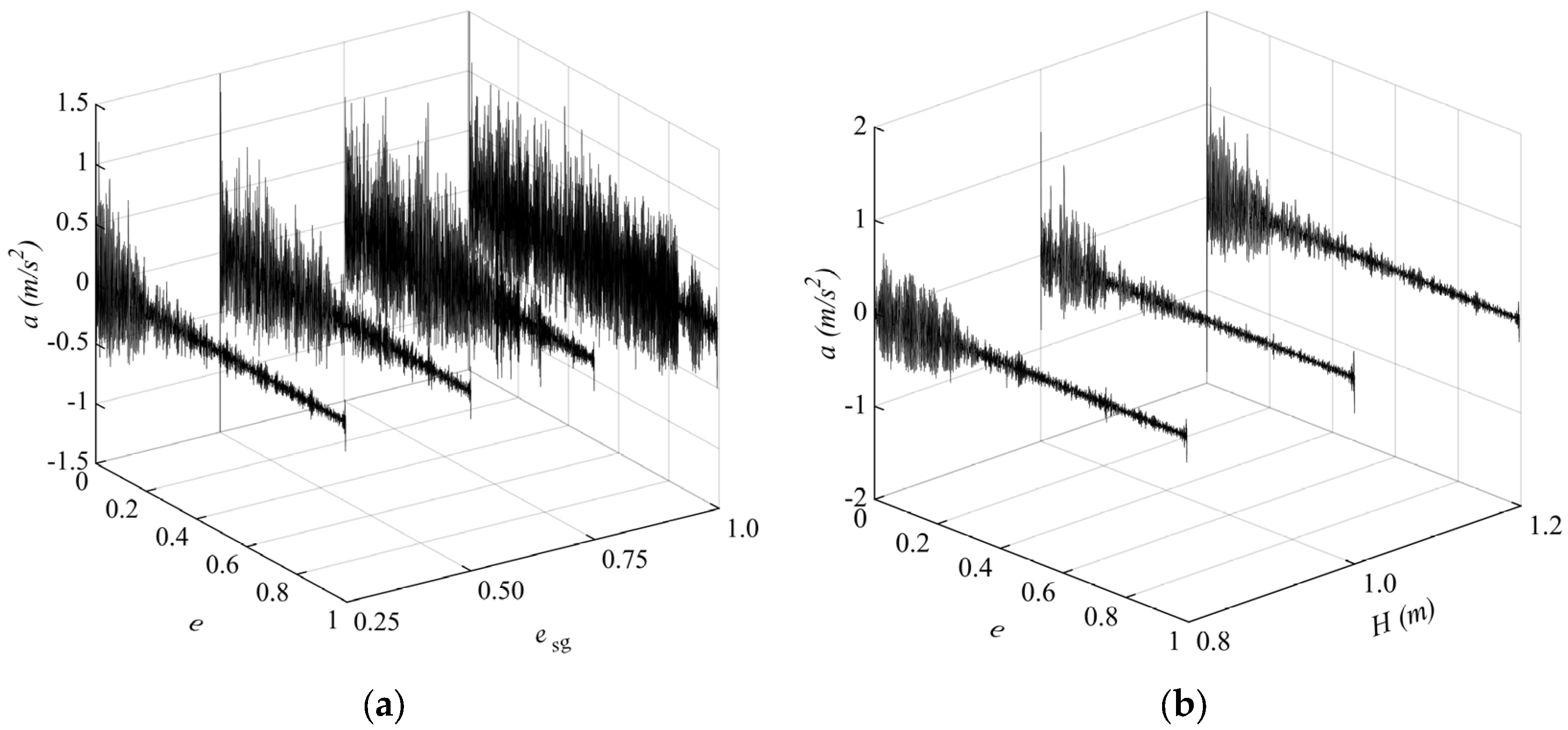
Figure 7 shows the acceleration of the slip–stick vibration in the gate-closing process. It is seen that the variation in acceleration is consistent with that of the hoist-force fluctuation. Under the same upstream water depth, the esg significantly affects the variation characteristics of the vibration acceleration in Figure 7a. As the esg increases, both the time of the gate slip–stick vibration stage and the amplitude of vibration acceleration increase. Nevertheless, as shown in Figure 7b, the upstream water depth has an effect on the intensity of the vibration acceleration at a given esg but has no significant influence on the time-history variation characteristics.
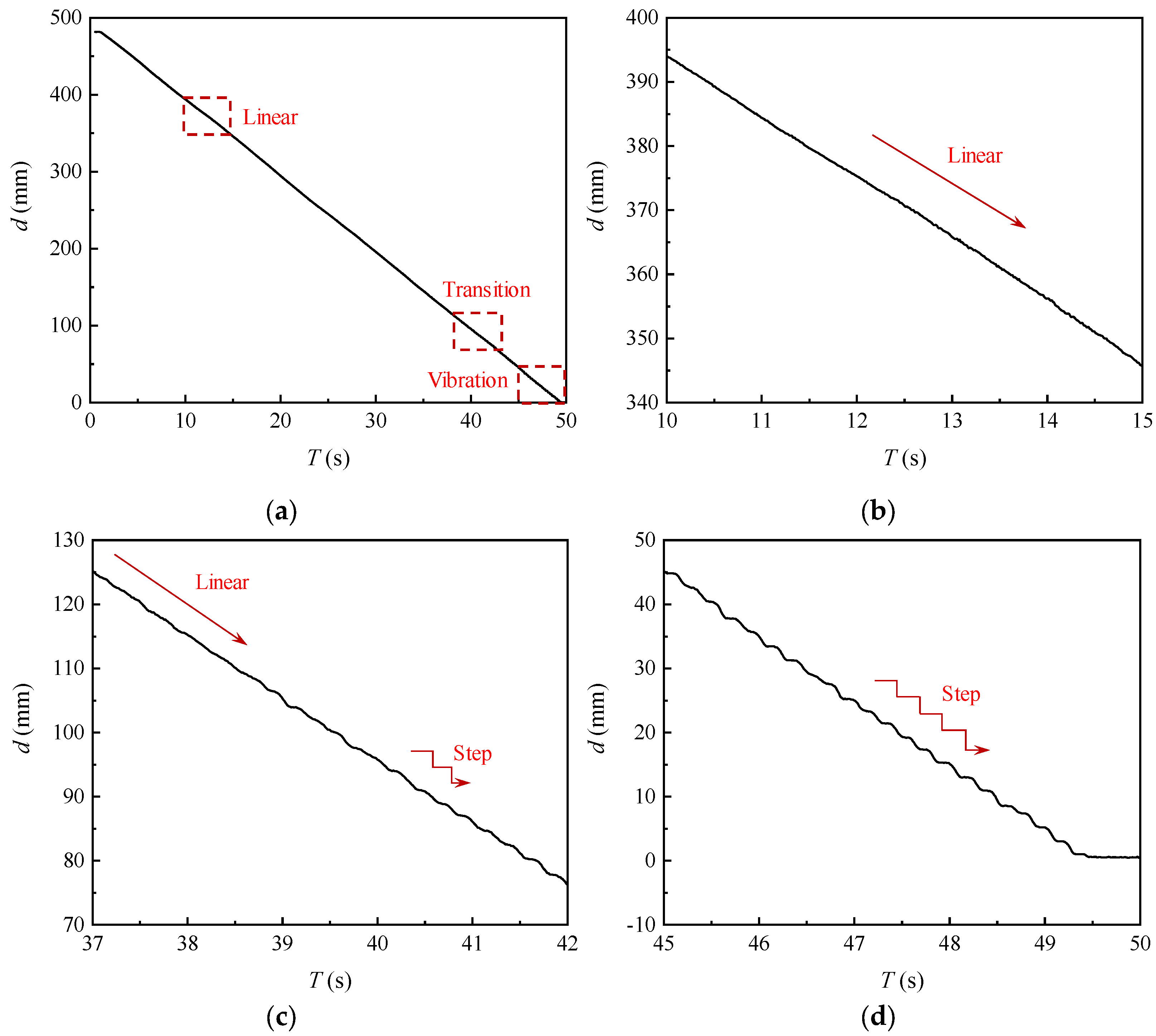
Figure 8a shows the displacement in the gate-closing process at H = 1.2 m and esg = 0.25. The displacement of the plane gate can be divided into three stages: non-vibration, transition and slip–stick vibration. In the non-vibration stage, the displacement decreases linearly (in Figure 8b). In the vibration stage, the displacement decreases in a stepwise manner (in Figure 8d) because of the gate slip–stick vibration with a flutter in the model test. In the transition stage from non-vibration to vibration, the linear decrease is gradually changed into a stepwise decrease (in Figure 8c).
Figure 9a shows the displacement in the gate-opening process at H = 1.2 m and esg = 0.25. The displacement can also be divided into vibration, impact and linear stages. When the opening degree of the plane gate is small, the displacement increases in a stepwise manner, as shown in Figure 9b. In the last stage, the slip–stick vibration disappears, and the displacement is changed linearly, as shown in Figure 9d. During the middle stage, the impact effect of the water–gas two-phase flow in the pressurized hole leads to a deviation of the gate-opening displacement from the original trend, indicating that the fluid excitation can disturb the intensity of gate vibration, as displayed in Figure 9c. However, the displacement increases in a stepwise manner at the impact stage, and the fluid excitation does not change the original slip–stick vibration characteristics.
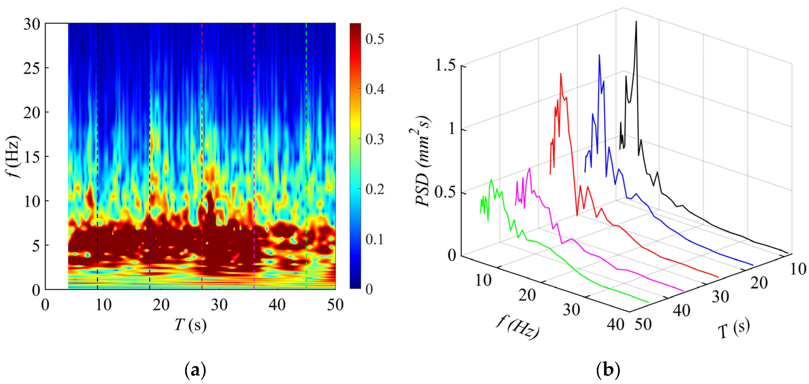
The vibration displacement spectra in the gate-closing process are obtained through wavelet analysis [22]. Figure 10 exhibits frequency spectra characteristic of vibration displacement in the gate-closing process at H = 1.2 m and esg = 0.25. As shown in Figure 10a, the red region denotes the significant region of the dominant frequency, and the dominant frequency tends to decrease and becomes more significant as the plane gate drops. Figure 10b exhibits the power spectral density (PSD) of the vibration displacement. The intensity of slip–stick vibration is increased, and the dominant frequency becomes more significant with the gate-closing time, which better reflects the variation characteristics of the slip–stick vibration in the gate-closing process.
Figure 11 shows the frequency characteristics of the vibration displacement in the gate-opening process at H = 1.2 m and esg = 0.25. In the initial stage of the gate-opening, the dominant frequency of slip–stick vibration is significant, as shown in Figure 11a. As the plane gate is lifted, the intensity of the slip–stick vibration weakens and the peak intensity of PSD decreases, as displayed in Figure 11b. A comprehensive comparison between Figure 10 and Figure 11 shows that the slip–stick vibrations in the gate-opening and gate-closing processes have the same characteristics. That is, the dominant frequency of slip–stick vibration gradually becomes significant, and the peak intensity of PSD gradually increases with the decrease in the opening degree of the plane gate.
4. Discussion
4.1. Influence of the Fluid Excitation on Slip–Stick Vibration
Fluid excitation near the gate bottom is considered to be an important cause of gate vibration in the existing research. In this study, the vertical fluid excitation and gate slip–stick vibration excitation are compared to explore the influence of fluid excitation at the gate bottom on slip–stick vibration, and special attention is paid to the comparison of intensity and frequency of the two. Due to the presence of upstream seals, the water pressure at the gate top has a negligible influence on the vibration. The fluid excitation mainly indicates the pressure fluctuation at the gate bottom, and its mean pressure has little influence on gate vibration. The fluid excitation is equal to the product of the flow pulsating pressure at the gate bottom and its area, and it is related to the flow field behind the plane gate. In the full-flow period, a group of vortices at the gate bottom may fall off, which has a great impact on the fluid excitation. There is a violent turbulent flow behind the gate and large-flow pulsating pressure near the gate bottom in the transition period. In the open-flow period behind the plane gate, water is mixed with air at the gate bottom, and a cavity area is formed near the gate bottom. The water streamlines are deflected near the gate bottom and form a contraction. The effect of the water–gas mixture is weakened, causing a small pulsating pressure at the gate bottom. In addition, the gate vibration excitation is directly reflected by the hoist-force fluctuation, which is consistent with the slip–stick vibration of the plane gate.
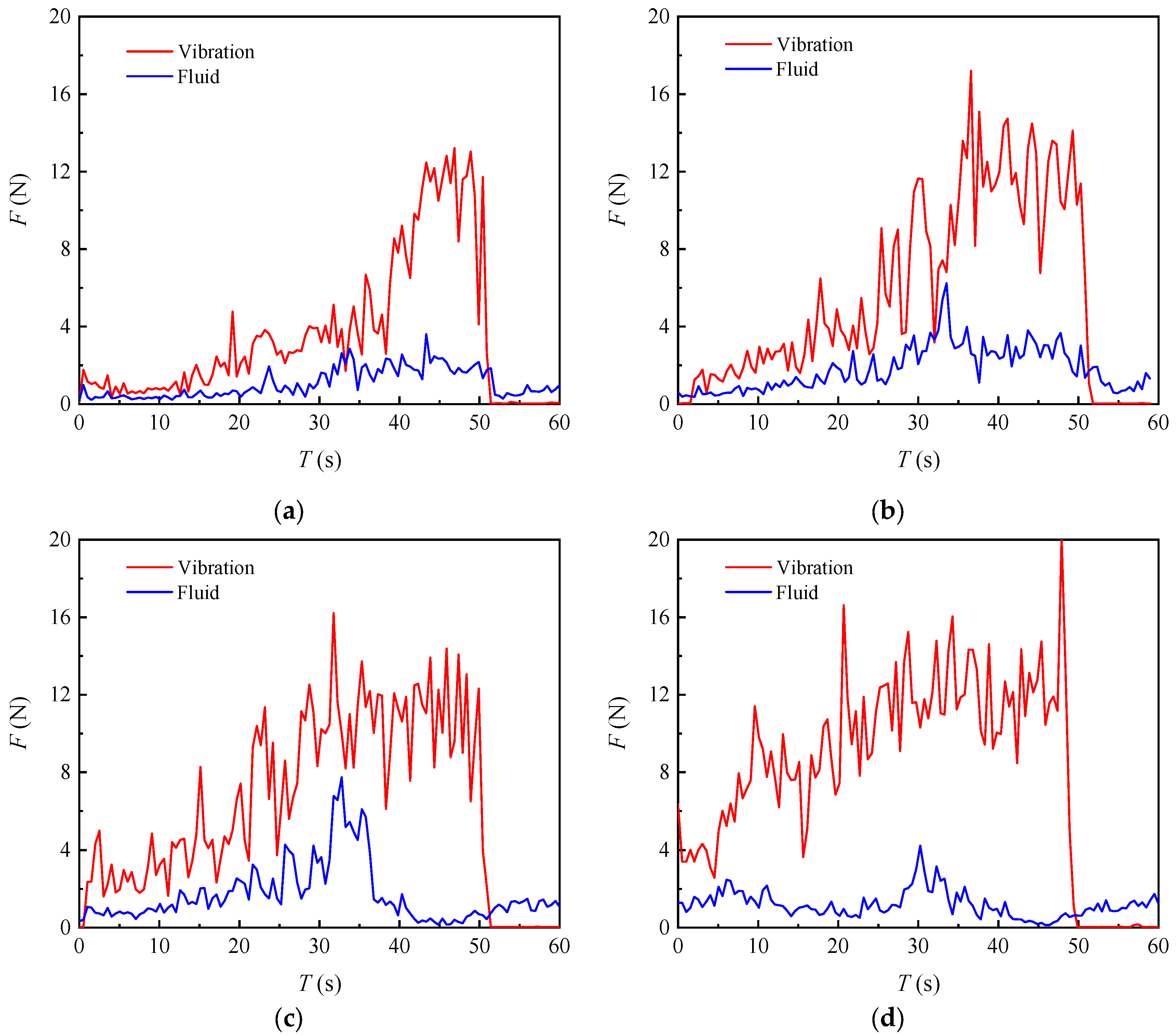
Figure 12 shows a comparison between the vibration excitation and fluid excitation for different opening degrees of the service gate at H = 1.2 m. As shown in Figure 12a, the flow is in a full-flow state at esg = 0.25, and the gate bottom area can interact with the flow for a long time. There is little difference between the vibration excitation and the fluid excitation in the initial gate-closing stage. However, no significant slip–stick vibration of the plane gate is found in this stage, which cannot explain the influence of fluid excitation on slip–stick vibration. As the plane gate continues to drop, there is a large difference between fluid excitation and gate slip–stick vibration excitation. It should be noted that the vibration excitation changes significantly, and the fluid excitation is relatively small when the opening ratio of the plane gate is small. For other opening degrees of the service gate in Figure 12b–d, there is a big gap between the fluid excitation and vibration excitation. To sum up, the fluid excitation is small, which does not match the slip–stick vibration excitation of the plane gate.
Figure 13 shows the relationship between the fluid excitation and the slip–stick vibration excitation in the gate-opening process at H = 1.2 m. Because the water–gas two-phase flow impacts the plane gate in the pressurized hole, as displayed in Figure 13, the vibration excitation and fluid excitation coincide in order of magnitude, indicating that fluid excitation can excite gate vibration. But, in fact, it should be noted that the drastic fluid excitation at the gate bottom would cause gate vibration only under the condition of there being an impact zone caused by the water–gas two-phase flow. The drastic vibration is different from that in other gate-opening stages and the gate-closing process. If there is no impact zone, the fluid excitation is relatively small, and the effective value is approximately 1.0 N during the gate-opening process. Nevertheless, the gate vibration excitation is relatively large (10.0 N), which is about 10 times the fluid excitation. Hence, the fluid excitation would not excite the slip–stick vibration under normal circumstances.
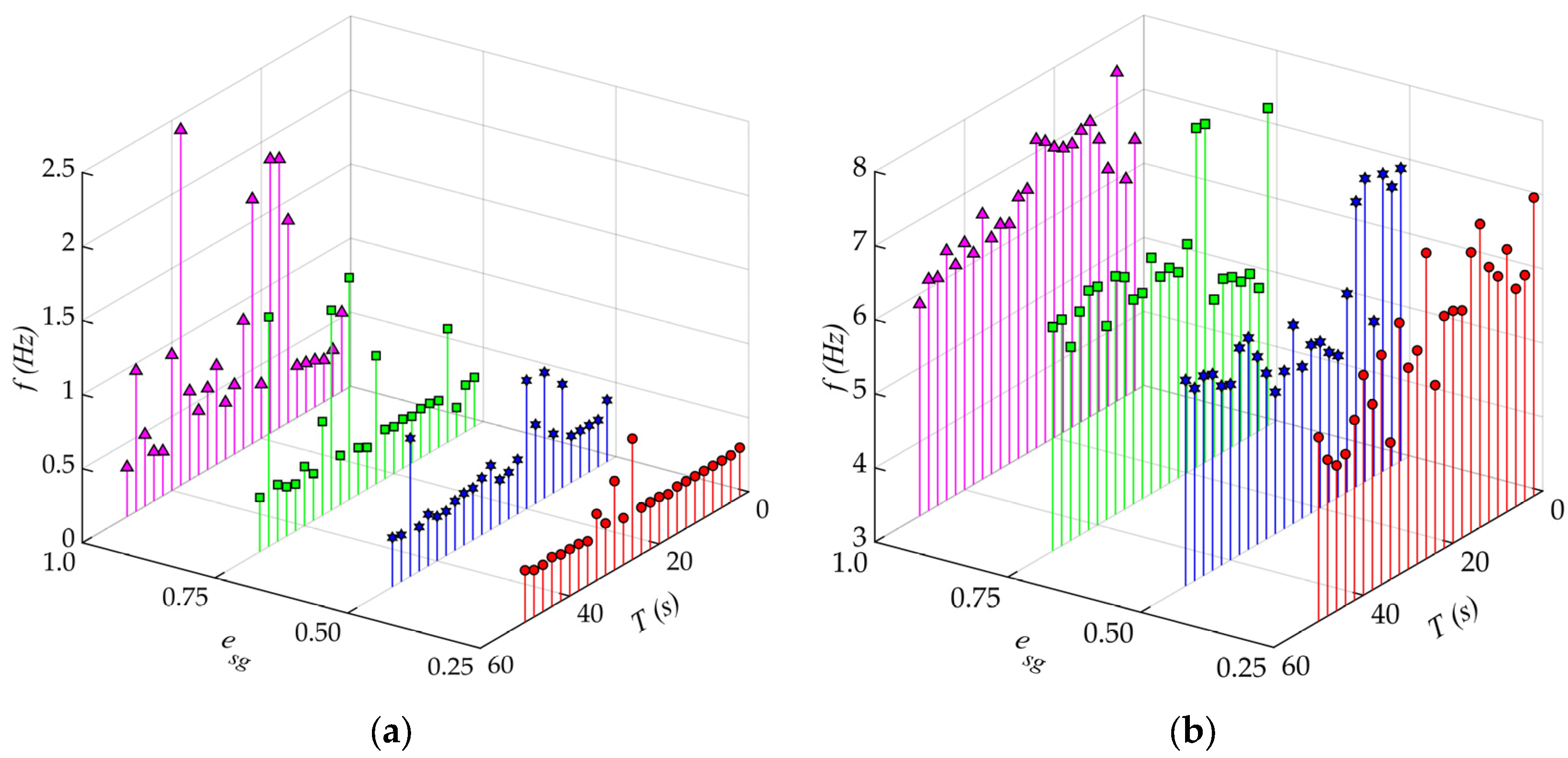
From a frequency point of view, the slip–stick vibration of the plane gate is simplified into a single degree of freedom vibration [15,23,24,25], and the natural frequency is ωn = (where E is the elastic modulus of steel rope, A is the cross sectional area of steel rope, L is the length of steel rope and m is the system mass). The length of steel rope increases, and the natural frequency of the equivalent system decreases, as the plane gate drops. As a result, the theoretical vibration frequency in the model test is reduced from 6.02 Hz to 5.72 Hz. Figure 14 shows the frequencies of the pulsating pressure at the gate bottom and slip–stick vibration in the gate-closing process at H = 1.2 m. It is seen that the slip–stick vibration in the gate-closing process is nonlinear, and its dominant frequency decreases from 7.0 Hz to 5.6 Hz as the opening degree of the plane gate decreases in Figure 14b. The vibration frequency is mostly consistent with the theoretical frequency, which indicates that the slip–stick vibration is a self-excited vibration. Nevertheless, the dominant frequency of the pulsating pressure near the gate bottom, as displayed in Figure 14a, is relatively small, about 0.5~1.5 Hz. There is a great difference between the pulsating pressure and slip–stick vibration.
Figure 15 shows a frequency comparison between the pulsating pressure and the slip–stick vibration in the gate-opening process at H = 1.2 m. It is seen that the frequency of the pulsating pressure is small for the different esg values, as shown in Figure 15a. As the opening degree of the plane gate increases, the slip–stick vibration frequency increases gradually in Figure 15b. It is found that there is a good agreement between the gate-opening and gate-closing processes. To sum up, it is believed that the slip–stick vibration in the gate-closing or gate-opening processes is not caused by fluid excitation at the gate bottom based on the difference of the intensity and frequency between fluid excitation and slip–stick vibration excitation.
4.2. Influence of Friction Factors on Slip–Stick Vibration
Another question that needs to be addressed is the influence of friction factors on the slip–stick vibration of the plane gate. In order to compare with the rusted iron support, a stainless-steel support was selected. The main difference between the two models was the roller material used, and the gate mass and seals were the same. The friction coefficient of the rusted iron roller support is approximately 0.037, and the friction coefficient of the stainless-steel roller support is about 0.016.
Figure 16 shows the influence of the plane gate support material on the slip–stick vibration at H = 1.2 m. As can be seen from Figure 16, the slip–stick vibration intensity of the stainless-steel supported gate is significantly reduced compared with that of the rusted-iron supported gate under the same water level, indicating that the friction characteristics between the gate support and the track cause the difference in the slip–stick vibration intensity. However, there are few studies on the friction characteristics between gate supports and tracks. In the different gate-support-material model tests, the fluid excitation acting on the plane gate body is almost the same as in the gate-closing process, which indicates that the fluid excitation has similar effects on the plane gate for the two model tests. When the plane gate is supported by a stainless-steel support instead of a rusted-iron support, the friction factor between the gate and track is changed, which mainly reflects in a different slip–stick vibration intensity in the model test results. Hence, the model results reveal that the friction characteristic of the plane gate support is the direct factor causing the slip–stick vibration of the plane gate, which can prove the rationality of the simplification of the friction relationship between the support and the track in the theoretical model [19,20].
Figure 17 shows the influence of slip–stick vibration on the pulsating pressure at the gate bottom. The pulsating pressure for the rusted-iron support gate is obviously greater than that for the stainless-steel support gate at esg = 0.25, indicating that the slip–stick vibration can increase the pulsating pressure at the gate bottom. However, the difference in the intensity of the gate vibration is obvious, and the difference in the pulsating pressure at the bottom for the different support gates is small at esg = 0.75, compared with Figure 16b and Figure 17b. The reason for this phenomenon is that the flow in the pressurized hole quickly enters the transition state of open and full flow when the esg is large, and the influence of gate slip–stick vibration on the pulsating pressure at the gate bottom is covered by the pressure pulsation caused by the water–gas two-phase flow in the pressurized hole. The influence of slip–stick vibration on the pulsating pressure of the gate bottom cannot be accurately analyzed. After that, the flow at the gate bottom completely empties, and the gate bottom directly contacts with the air. The slip–stick vibration does not influence the pulsating pressure at the gate bottom. Thus, the influence of the slip–stick vibration on the pulsation pressure at the gate bottom is relatively weak compared with the influence of the flow change caused by the boundary conditions on the pulsation pressure at the gate bottom.
4.3. Friction-Induced Vibration and Flow-Induced Vibration
The flow-induced vibration of a plane gate is thought to be caused by the separation and reattachment of flow near the gate bottom [8,26,27,28]. Similar findings are reported for vortex-induced vibration of pipelines in ocean engineering [29,30]. For a fixed plane gate opening, the gate vibration mainly represents a flow-induced vibration. The vertical constraint of the plane gate is generally small, and the outflow behind the gate is submerged, which is also the key control condition for the previous studies. The submerged outflow condition ensures the contact between the gate bottom and the flow and produces a direct fluid–structure interaction. Subsequently, researchers have mainly investigated the vortex shedding characteristics of the gate bottom under this condition. However, the fluid excitation at the gate bottom is small under the condition of open flow behind the gate, and the flow pulsation can hardly motivate the vertical vibration of the plane gate.
Compared to the model results of the gate supported by different materials, it is found that the fluid excitation at the plane gate is basically the same in the gate-closing process. When the gate support is changed from rusted iron to stainless steel, the friction characteristics between the gate support and the track alter, which is directly reflected in the difference in the slip–stick vibration intensity of the plane gate. In addition, the transformation of slide–static friction in the friction theory originates from the relative movement of the contact surface. That is, the relative movement of the contact surface leads to nonlinear variation in the friction coefficient, and the resulting vibration is called the friction-induced vibration. For a plane gate, this relative motion corresponds to the gate being in motion. But, in fact, there is no relative movement between the gate support and the track when the plane gate is in a fixed opening. There is no nonlinear variation in the friction coefficient of the contact surface, and the slip–stick vibration cannot occur. Thus, the slip–stick vibration of the plane gate is a kind of friction-induced vibration caused by the gate movement, for example, the gate-closing and gate-opening processes.
5. Conclusions
In this study, the slip–stick vibration behavior of a plane gate in transient water was analyzed through an experimental model test. The effects of flow conditions and gate support materials on the nonlinear dynamics of the plane gate were investigated. It was found that the friction factor between the gate support and track has a strong influence on slip–stick vibration. From the results obtained, the following conclusions can be drawn:
- (i)
- The intensity and period of the slip–stick vibration of the plane gate both increase with the opening degree of the plane gate decreasing. The frequency of the slip–stick vibration of the plane gate is consistent with the simplified natural frequency, indicating that the slip–stick vibration is a nonlinear self-excited vibration.
- (ii)
- The variation intensity and dominant frequency between the slip–stick vibration and fluid excitation of the plane gate have a significant difference. Fluid excitation acting on the plane gate is not the main cause of gate slip–stick vibration. The slip–stick vibration intensity can be influenced by special fluid excitation, but the vibration mechanism would not change.
- (iii)
- The friction factor between gate support and track is the main cause of the slip–stick vibration of the plane gate. The slip–stick vibration is the friction-induced vibration caused by the gate’s active motion.
Friction-induced vibration related to friction factors in the gate-opening and gate-closing processes should be paid more attention in the subsequent study of the slip–stick vibration of plane gates. The intensity of slip–stick vibration can be reduced, and the influence on practical engineering safety can be reduced, by increasing the lubrication of the gate support and track. At the same time, the metal support of the plane gate is in a wet or underwater environment for a long time, resulting in a certain degree of corrosion of the metal structure. The corrosion process and the quantification of the impact of corrosion on the friction coefficient need to be further investigated.
Author Contributions
Conceptualization, Y.W.; methodology, Y.W.; formal analysis, Z.L.; investigation, Y.W.; resources, G.X.; data curation, Y.W. and D.Y.; writing—original draft preparation, Y.W.; writing—review and editing, Y.W.; supervision, G.X.; funding acquisition, G.X. All authors have read and agreed to the published version of the manuscript.
Funding
The authors gratefully acknowledge the support provided by the National Natural Science Foundation of China (Grant Number 51779166).
Data Availability Statement
The raw data supporting the conclusions of this article will be made available by the authors on request.
Acknowledgments
The authors gratefully acknowledge the editors and anonymous reviewers for their insightful and professional suggestions.
Conflicts of Interest
Author Zhicheng Liu was employed by the company Changchun Construction Engineering Survey Planning and Design Co., Ltd., Xuzhou branch. The remaining authors declare that the research was conducted in the absence of any commercial or financial relationships. There are no potential conflicts of interest.
References
- Lian, J.J.; Chen, L.; Liang, C.; Liu, F. Presentation and verification of an optimal operating scheme aiming at reducing the ground vibration induced by high dam flood discharge. Int. J. Environ. Res. Public Health 2020, 17, 377. [Google Scholar] [CrossRef] [PubMed]
- Lian, J.J.; Chen, L.; Ma, B.; Liang, C. Analysis of the cause and mechanism of hydraulic gate vibration during flood discharging from the perspective of structural dynamics. Appl. Sci. 2020, 2, 629. [Google Scholar] [CrossRef]
- Ma, C.; Sheng, C.M.; Lian, J.J.; Ma, B.; Liu, F. Failure analysis of a leaf gate jammed in closing process. Eng. Fail. Anal. 2020, 110, 104391. [Google Scholar] [CrossRef]
- Liu, X.P.; Zhao, L.H.; Cao, H.Y.; Sun, X.-P. Lifting force acting on a gate with high head. J. Hydrodyn. 2011, 23, 379–383. [Google Scholar] [CrossRef]
- Hardwick, J.D. Flow-induced vibration of vertical-lift gate. ASCE J. Hydraul. Div. 1974, 100, 631–644. [Google Scholar] [CrossRef]
- Kolkman, P.A. A simple scheme for calculating the added mass of hydraulic gates. J. Fluids Struct. 1988, 2, 339–353. [Google Scholar] [CrossRef]
- Naudascher, E.; Rockwell, D. Oscillator-model approach to the identification and assessment of flow-induced vibrations in a system. J. Hydraul. Res. 1980, 18, 59–82. [Google Scholar] [CrossRef]
- Thang, N.D. Gate vibrations due to unstable flow separation. J. Hydraul. Eng. 1990, 116, 342–361. [Google Scholar] [CrossRef]
- Jongeling, T.H.G. Flow-induced self-excited in-flow vibrations of gate plates. J. Fluids Struct. 1988, 2, 541–566. [Google Scholar] [CrossRef]
- Thang, N.D.; Naudascher, E. Vortex-excited vibrations of underflow gates. J. Hydraul. Res. 1986, 24, 133–151. [Google Scholar] [CrossRef]
- Thang, N.D.; Naudascher, E. Self-excited vibrations of vertical-lift gates. J. Hydraul. Res. 1986, 24, 391–404. [Google Scholar] [CrossRef]
- Yang, M.; Lian, J.J.; Lin, J.Y. Analysis and calculation of flow-induced vertical vibration of plate gate. J. Basic Sci. Eng. 1995, 3, 61–66. (In Chinese) [Google Scholar]
- Yang, M.; Lian, J.J.; Lin, J.Y. Excitation mechanism of flow induced plane gate vibration. J. Hydrodyn. 1997, 4, 437–449. (In Chinese) [Google Scholar]
- Naudascher, E. Flow-induced vibrations at hydraulic structures. J. Fluids Struct. 1987, 1, 265–298. [Google Scholar] [CrossRef]
- Erdbrink, C.D.; Krzhizhanovskaya, V.V.; Sloot, P. Reducing cross-flow vibrations of underflow gates: Experiments and numerical studies. J. Fluids Struct. 2014, 50, 25–48. [Google Scholar] [CrossRef]
- Jafari, A.; Kabiri-Samani, A.; Behnamfar, F. Flow-induced horizontal and vertical vibration of sluice gates. Proc. Inst. Civ. Eng.-Water Manag. 2018, 171, 152–162. [Google Scholar] [CrossRef]
- Kostecki, S.W. Numerical analysis of hydrodynamic forces due to flow instability at lift gate. Arch. Civ. Mech. Eng. 2011, 11, 943–961. [Google Scholar] [CrossRef]
- Novak, G.; Mlačnik, J.; Bombač, M.; Vošnjak, S. Hydrodynamic forces during the operation of a model radial gate. J. Appl. Water Eng. Res. 2017, 51, 70–77. [Google Scholar] [CrossRef]
- Ji, S.K.; Zhou, L.J.; Han, G.; Duanmu, L.M.; Lin, J.Y. Vibration analysis of sluice gate closure process for diversion of Yellow River. Water Resour. Hydropower Eng. 2001, 12, 64–66. (In Chinese) [Google Scholar]
- Liang, C.; Zhang, J.J.; Lian, J.J.; Liu, F. Research on slip-stick vibration of emergency gate induced by high dam flood discharge. J. Hydraul. Eng. 2018, 49, 1503–1511. (In Chinese) [Google Scholar]
- Duan, Y.; Xu, G.B.; Wang, Y.Z.; Yang, D. The middle Huaihe River stability analysis and optimization of hydrological chaos forecasting model. Geomat. Nat. Hazards Risk 2020, 11, 1805–1826. [Google Scholar] [CrossRef]
- Billeter, P.; Staubli, T. Flow-induced multiple-mode vibrations of gates with submerged discharge. J. Fluids Struct. 2000, 14, 323–338. [Google Scholar] [CrossRef]
- Wang, Y.Z.; Xu, G.B.; Li, W.S.; Liu, F.; Duan, Y. Characteristics of plane gate vibration and holding force in closing process by experiments. Appl. Sci. 2020, 10, 6111. [Google Scholar] [CrossRef]
- Wang, Y.Z.; Xu, G.B.; Liu, F. Holding force and vertical vibration of emergency gate in the closing process: Physical and numerical modelling. Appl. Sci. 2021, 11, 8440. [Google Scholar] [CrossRef]
- Wang, Y.Z.; Xu, G.B.; Liu, F. Numerical inversion and influencing factors of creeping vibration of emergency gate. J. Hydroelectr. Eng. 2022, 41, 55–62. (In Chinese) [Google Scholar]
- Ishii, N. Flow-induces vibration of long-span gates part I: Model development. J. Fluids Struct. 1992, 6, 539–562. [Google Scholar] [CrossRef]
- Ishii, N.; Knisely, C. Flow-induced vibration of long-span gates due to shed vortices. JSME Int. J. 1992, 35, 1–8. [Google Scholar]
- Yang, T.T.; He, S.H.; Shen, C.Y.; Yang, Q. Fluid-induced vibrations test of hydraulic plane gate for different conditions. In Proceedings of the International Conference on Sensors, Nanjing, China, 11–13 November 2016; pp. 1083–1089. [Google Scholar]
- Dai, H.L.; Wang, L.; Qian, Q.; Ni, Q. Vortex-induced vibrations of pipes conveying fluid in the subcritical and supercritical regimes. J. Fluids Struct. 2013, 39, 322–334. [Google Scholar] [CrossRef]
- Zhu, H.J.; Gao, Y. Effect of gap on the vortex-induced vibration suppression of a circular cylinder using two rotating rods. Ships Offshore Struct. 2018, 13, 119–131. [Google Scholar] [CrossRef]
Figure 1.
Schematic diagram of experiment setup.

Figure 2.
Water pressure in gate-closing process: (a) gate bottom; (b) gate top. The left side is the pressure, the right side is the gate opening degree. The red line denotes the gate opening degree.
Figure 2.
Water pressure in gate-closing process: (a) gate bottom; (b) gate top. The left side is the pressure, the right side is the gate opening degree. The red line denotes the gate opening degree.

Figure 3.
Water pressure in gate-opening process: (a) H = 1.0 m; (b) H = 1.2 m.

Figure 4.
Influence of service gate opening degree on hoist force: (a) gate-closing process; (b) gate-opening process.
Figure 4.
Influence of service gate opening degree on hoist force: (a) gate-closing process; (b) gate-opening process.

Figure 5.
Influence of service gate opening degree on hoist-force fluctuation (H = 1.0 m): (a) gate-closing process; (b) gate-opening process.
Figure 5.
Influence of service gate opening degree on hoist-force fluctuation (H = 1.0 m): (a) gate-closing process; (b) gate-opening process.

Figure 6.
Influence of upstream water depth on hoist-force fluctuation: (a) gate-closing process; (b) gate-opening process.
Figure 6.
Influence of upstream water depth on hoist-force fluctuation: (a) gate-closing process; (b) gate-opening process.

Figure 7.
Characteristics of vibration acceleration in gate-closing process: (a) H =1.2 m; (b) esg = 0.25.
Figure 7.
Characteristics of vibration acceleration in gate-closing process: (a) H =1.2 m; (b) esg = 0.25.

Figure 8.
Displacement in gate-closing process: (a) overall; (b) linear; (c) transition; (d) vibration.
Figure 8.
Displacement in gate-closing process: (a) overall; (b) linear; (c) transition; (d) vibration.

Figure 9.
Displacement in gate-opening process: (a) overall; (b) vibration; (c) impact; (d) linear.

Figure 10.
Spectra of slip–stick vibration displacement in gate-closing process: (a) overall; (b) special time.
Figure 10.
Spectra of slip–stick vibration displacement in gate-closing process: (a) overall; (b) special time.

Figure 11.
Spectra of slip–stick vibration displacement in gate-opening process: (a) overall; (b) special time.
Figure 11.
Spectra of slip–stick vibration displacement in gate-opening process: (a) overall; (b) special time.

Figure 12.
Force comparison between fluid excitation and slip–stick vibration in gate-closing process: (a) esg = 0.25; (b) esg = 0. 50; (c) esg = 0.75; (d) esg = 1.0.
Figure 12.
Force comparison between fluid excitation and slip–stick vibration in gate-closing process: (a) esg = 0.25; (b) esg = 0. 50; (c) esg = 0.75; (d) esg = 1.0.

Figure 13.
Force comparison between fluid excitation and slip–stick vibration in gate-opening process: (a) esg = 0.25; (b) esg = 0.50; (c) esg = 0.75; (d) esg = 1.0.
Figure 13.
Force comparison between fluid excitation and slip–stick vibration in gate-opening process: (a) esg = 0.25; (b) esg = 0.50; (c) esg = 0.75; (d) esg = 1.0.

Figure 14.
Frequency comparison in gate-closing process: (a) pulsating pressure; (b) slip–stick vibration.
Figure 14.
Frequency comparison in gate-closing process: (a) pulsating pressure; (b) slip–stick vibration.

Figure 15.
Frequency comparison in gate-opening process: (a) Pulsating pressure; (b) Slip–stick vibration.
Figure 15.
Frequency comparison in gate-opening process: (a) Pulsating pressure; (b) Slip–stick vibration.

Figure 16.
Effect of gate support material on slip–stick vibration: (a) esg = 0.25; (b) esg = 0.75.

Figure 17.
Influence of slip–stick vibration on pulsating pressure (H = 1.2 m): (a) esg = 0.25; (b) esg = 0.75.
Figure 17.
Influence of slip–stick vibration on pulsating pressure (H = 1.2 m): (a) esg = 0.25; (b) esg = 0.75.

Disclaimer/Publisher’s Note: The statements, opinions and data contained in all publications are solely those of the individual author(s) and contributor(s) and not of MDPI and/or the editor(s). MDPI and/or the editor(s) disclaim responsibility for any injury to people or property resulting from any ideas, methods, instructions or products referred to in the content. |
© 2024 by the authors. Licensee MDPI, Basel, Switzerland. This article is an open access article distributed under the terms and conditions of the Creative Commons Attribution (CC BY) license (https://creativecommons.org/licenses/by/4.0/).
Share and Cite
MDPI and ACS Style
Wang, Y.; Xu, G.; Liu, Z.; Yang, D. Experimental Study on the Slip–Stick Vibration of Plane Gate. Water 2024, 16, 912. https://doi.org/10.3390/w16060912
AMA Style
Wang Y, Xu G, Liu Z, Yang D. Experimental Study on the Slip–Stick Vibration of Plane Gate. Water. 2024; 16(6):912. https://doi.org/10.3390/w16060912
Chicago/Turabian StyleWang, Yanzhao, Guobin Xu, Zhicheng Liu, and Deming Yang. 2024. "Experimental Study on the Slip–Stick Vibration of Plane Gate" Water 16, no. 6: 912. https://doi.org/10.3390/w16060912
Note that from the first issue of 2016, this journal uses article numbers instead of page numbers. See further details here.