
A Predictive Analysis Method of Shafting Vibration for the Hydraulic-Turbine Generator Unit

1
State Key Laboratory of Simulation and Regulation of Water Cycles in River Basins, China Institute of Water Resources and Hydropower Research, Beijing 100038, China
2
College of Water Resources and Civil Engineering, China Agricultural University, Beijing 100083, China
*
Author to whom correspondence should be addressed.
Water 2022, 14(17), 2714; https://doi.org/10.3390/w14172714
Submission received: 26 July 2022
/
Revised: 26 August 2022
/
Accepted: 29 August 2022
/
Published: 31 August 2022
(This article belongs to the Special Issue Emerging Solutions for Active Water Governance: Intellectual Decision and Smart Control)
Abstract
:The shafting vibration for the Hydraulic-Turbine Generator Unit (HGU) inevitably affects the safe and stable operation of the Units. Excessive shafting vibration could cause fatigue damage of materials, which eventually leads to malfunction of HGU and even results in damage accidents in serious cases. Generally speaking, the vibration is mainly generated from the high-speed rotation of the shafting, and mechanical, hydraulic, and electrical factors as the vibration exciting sources may be coupled all to cause a vibration of the HGU, so it is necessary to take the whole shafting as a specific object of study. In recent years, many scholars have conducted much research on them and their results are focused more on how to control the influence of external excitation sources of vibration, but still lack consideration of the shafting’s internal mechanism of vibration. In this paper, a predictive analysis method is proposed to reveal the internal mechanism of vibration. Starting from the analysis of natural vibration characteristics of the shafting, this study establishes the finite element calculation model of the shafting of the HGU based on the finite element analysis method. By selecting appropriate research methods and calculation procedures, the modal analysis of the dynamic characteristics of the shafting structure is carried out. Finally, the first ten-order natural vibration characteristics and critical rotational speed of the shafting structure are successfully calculated, and the results conform to the basic laws of shafting vibration. In addition, by comparing the relationship between rotational frequency such as the rated speed, runaway speed, and critical speed of the shafting, the possibility of resonance of the HGU is analyzed and predicted, and then some suggestions for optimization design such as increasing the shafting’s stiffness and balancing its mass distribution are proposed. Therefore, this study provides a basis for guiding the structural design and optimization of the shaft system in engineering, and avoids the resonance caused by the excitation source such as rotational frequency, thereby ensuring the safe and stable operation of the HGU.
1. Introduction
At present, along with the continuous increase of the unit capacity and operating head of the Hydraulic-Turbine Generator Unit (HGU), the safety and stability of the HGU have become increasingly highlighted, and the vibration is one of the important factors affecting the stable operation of the Unit. Excessive vibration not only causes fatigue damage to materials, shortens the service life of the equipment, but also causes the HGU to fail to operate normally. In severe cases, it may cause damage accidents to HGU and eventually lead to causing huge economic losses [1,2]. In recent years, various extents of vibration problems have occurred in hydropower plants (HPP), such as Xiaolangdi, Yantan, Wuqiangxi, and Wanjiazhai HPP in China; Guri HPP in Venezuela, and Grand Coulee HPP in the United States. Due to the vibration, some cause cracks in the runner blades, tearing of the draft tube; some cause fatigue of parts or welds, which leads to form or expand cracks until they break; and some even cause resonance in the powerhouse and adjacent hydraulic structures, which eventually endangers the safe and stable operation of the HPP [3,4,5]. Therefore, the predictive analysis and control of the vibration phenomenon of the HGU is a significant factor that must be considered during the design, construction, and operation of the HPP [6].
In the actual operation of the HGU, there should be more or less vibration due to the high-speed rotation of the shafting, the research on which has always been highly valued by the academic and engineering circles. Due to the particularity of the working medium of the HGU, the causes of the vibration are much more complicated than other rotational machinery. In addition to the vibration caused by mechanical unbalance, the influence of hydrodynamic pressure of the fluid and the unbalance of the electromagnetic force should also be considered. Therefore, in the actual operation of the Unit, the combination of mechanical unbalance factors, hydraulic unbalance factors and electromagnetic unbalance factors jointly cause the vibration of the shaft system [7]. In recent years, the research on the vibration of the HGU has made important progress in the depth and breadth of research compared with the traditional research methods. By drawing on mathematics, physics and other basic disciplines and combining them with computational technology, many new research fields have been explored, and thus research and experimental methods have become more modernized, and with it, more and more in-depth and significant results and findings have been disclosed on the mechanism of the HGU’s vibration, which contributes to pushing ahead with the theory and practice in engineering [8].
In terms of mechanical factors, due to mechanical unbalance caused by manufacturing, installation, maintenance and other factors, the shafting and supporting structure of the HGU deviate from the symmetry, which results in vibration and unstable operation of the Unit. Numerous studies have shown that the main reasons for mechanical unbalance are: the main shaft is not straight; the mass of the rotating parts is unbalanced, such as the mass unbalance of the turbine runner and the generator rotor; the rotational parts are not concentric with the fixed parts, resulting in friction or collision; clearance of guide bearing pad is excessive or lack of lubrication; thrust bearing adjustment is not appropriate or the surface of thrust bearing pads is not level, etc. These factors cause mechanical vibration [9,10,11,12,13]. It has also been found in practice that due to the improper manufacturing or installation quality of the generator, or the bending and deformation of the generator shaft system, the outer circle of the generator rotor is eccentric relative to the inner circle of the stator. This eccentricity also leads to a non-uniform air gap that results in an unbalanced magnetic pull. Unbalanced magnetic pulling force and centrifugal force act on the shafting, which causes lateral vibration and torsional vibration of the shafting. The vibration caused by mechanical defects or faults has common characteristics in that the vibration frequency is mostly equal to the rotational frequency or a multiple of the rotational frequency, and the unbalanced force is generally horizontal and radial. In addition, the natural vibration characteristics of the shafting system determined by the structural design of the shafting system, such as the natural vibration frequency, the main vibration mode and the critical speed, have a fundamental effect on the vibration characteristics of the shafting system. The stiffness of the shafting structure and the stiffness coefficient of the guide bearing also affect the natural frequency, critical speed and main vibration mode of the shafting. Because as long as various excitation sources interacted with the natural vibration characteristics of the shafting structure, the actual vibration response characteristics are just shown [14,15,16,17].
In terms of hydraulic factors, all the energy driving the HGU comes from the kinetic energy of the fluid, which interacts with the rotational parts of the HGU. Due to the irregular flow channel shape of the turbine and the uncertainty of the rotation phenomenon, the internal flow field is so complex that it is very difficult to grasp the hydraulic vibration. Therefore, hydraulic vibration is one of the main vibration sources of the shaft system. More and more researches illustrate that the main factors that cause hydraulic vibration are as follows: the vibration caused by the Karman vortex; the vibration caused by the low-frequency vortex in the draft tube; the vibration caused by the unstable flow at the outlet of the stay vane; the vibration caused by unreasonable matching between the number of runner blades and the number of stay vanes of the hydraulic turbine; as well as the vibration caused by the cavitation effect, etc. Hydraulic factors have a significant impact on the shafting vibration, and its mechanism is also very complex due to the strongly coupled interaction with the turbulent flow, the research of which carried out by scholars in the past reveals the aforementioned results [18,19,20]. In addition, by summarizing the previous research results, it also can be found that hydraulic vibration varies with the working conditions of the HGU. If the working water head of the turbine is constant during operation, the amplitude of hydraulic vibration varies with the change of flow and load, while the load is constant, the hydraulic vibration under the condition of different heads is also different. However, if the water head and flow rate are constant, the hydraulic vibration is different due to the different cavitation coefficients of the turbine [21,22].
In terms of electrical factors, during the operation of the HGU, because the lines of magnetic force pass through the air gap between the rotor and the stator, a pulling force is generated between the stator and the rotor, i.e., magnetic pulling force. When the magnetic field is uniform under ideal conditions, the magnetic pulling force distributed on each point in the radial direction of the rotor is also uniform, and their resultant force should be zero so that the shafting could rotate in a balanced state. However, if there is an eccentricity between the rotor and the stator, the magnetic pulling force is also unbalanced, and the unbalanced magnetic pull could affect the dynamic characteristics of the shafting system which makes the vibration frequency change with the shafting rotation. Therefore, the vibration caused by electromagnetic factors mainly means that the vibration exciting force comes from the electromagnetic force of the electrical parts of the generator, which is characterized in that the vibration increases with the increasing of the excitation current [23,24,25]. The electromagnetic vibration of the HGU can be divided into two categories: one is rotational frequency vibration and the other is extreme frequency vibration (its frequency is usually up to 100 Hz). The frequency of rotational frequency vibration is usually equal to the Unit’s rotational frequency or its integral multiple, which is one of the main vibration sources of HGU with a large diameter. The main causes of the rotational frequency vibration are as follows: the air gap between the rotor and the stator is not uniform; the outer circle of the rotor or the inner cavity of the stator is not round; the rotor geometric centre is inconsistent with the rotational centre; there are a dynamic or static imbalance of the rotor as well as the short circuit between coil turns, etc. However, the extreme frequency vibration is usually formed by the interaction of the rotor magnetic field and the stator magnetic field, and the large or abnormal extreme frequency vibration usually occurs in the form of resonance. The extreme frequency vibration of the stator is a natural vibration that usually occurs in the yoke part of the stator core. The main causes of the extreme frequency vibration are as follows: the sub-harmonic magnetic potential of the stator fractional slots, which induces a vibration frequency of 100 Hz, and its amplitude increases with the increase of the load current; the magnetic potential generated by the circulating current in the parallel-circuit branch of the stator, which can induce a series of asymmetric sub-harmonic potentials, and cause extreme frequency vibration with a frequency of 100 Hz; the reverse magnetic potential induced by the negative sequence current, which causes the stator core to vibrate as a standing wave; as well as either the stator is not round, or the split stator is not tightly seamed. Up to now, much research and experiments regarding the unbalanced magnetic pull force carried out by many scholars have illustrated and testified the beneficial results hereinbefore, which have played a positive role in analyzing and understanding the electrical vibration mechanism [26,27,28].
In the actual operation of the HGU, these three factors are coupled with each other, showing complex characteristics of vibration response. In fact, the vibration of the HGU is mainly caused by the high-speed rotation of the shafting, so it is necessary to take the whole shafting as a specific object of study and analysis. Although many scholars tried to consider the above three factors in the predictive research of shafting vibration characteristics as much as possible, accurately simulating the vibration by considering all the above factors in one numerical calculation model still cannot be fully realized at present. Therefore, it is feasible and customary to select the representative influencing factors according to the actual situation of HGU and consider them in the specific model of the corresponding study [29,30]. In addition, the aforementioned factors caused by the unbalance of manufacturing, installation, maintenance and so on could be regarded as external vibration exciting sources, and their research results are focused too much on how to control the influence of external excitation sources with neglecting the exploration on the internal and inherent mechanism of shafting vibration. However, moderate vibration of the Unit is allowed in practical engineering, and only when the external excitation source is close to the natural vibration characteristics of the shafting structure, the resonance phenomenon that is most harmful to the Unit would appear. Long-time resonance will inevitably endanger the safe and stable operation of the Unit, which is not allowed in engineering. Therefore, in order to predict and evaluate whether the shafting could generate resonance or not, in addition to controlling the influence of the external excitation source, it is also necessary to fundamentally analyze and study the inherent vibration characteristics of the shafting structure, i.e., the study of the natural vibration characteristics, which are mainly determined by the structural design of the shafting.
The study of natural vibration characteristics includes the contents of traditional rotor dynamics research such as numerical calculation of natural frequency, critical speed, and mode shape, as well as the influence analysis of various factors on natural vibration characteristics [1,2,31,32,33]. Among them, the finite element modal analysis is not only a modern method to study the dynamic characteristics of the natural vibration of the structure, but also the application of the system identification method in the field of engineering. The modal analysis uses the modal coordinates corresponding to the main vibration modes of the undamped system to replace the physical coordinates, and decouple the differential equations with coupled coordinates into differential equations with independent coordinates, so as to calculate the modal parameters. Modes are the natural vibration characteristics of mechanical structures, and each mode has a specific natural frequency, damping ratio, and mode shape. These modal parameters could be obtained by numerical calculation or experimental analysis, and thus such a process of calculation or experimental analysis is called modal analysis. Vibration modes are inherent and integral characteristics of elastic structures. If the main modal characteristics of the structure in a certain susceptible frequency range are figured out by the modal analysis method, it is possible to predict the actual vibration response of the structure under the action of various external or internal vibration exciting sources within this frequency range, so as to make the structure design avoid resonance or vibrate at a specific frequency. Therefore, the modal analysis would be an important method to guide the dynamic design of structures and fault diagnosis of equipment in the future [34].
In conclusion, in order to explore and reveal the natural vibration characteristics of the shafting structure of the HGU, and combine with the needs of the research on the operation stability faced by the author in the actual hydropower project, this paper will conduct the finite element modal analysis research on the shafting structure of an HGU for a newly built hydropower plant in Turkey. By calculating and simulating the natural vibration characteristics of the shafting structure, it is able to predict the possibility of resonance occurring in the shafting under the action of relevant vibration sources, thereby evaluating the stability and safety of the Unit’s structural design, as well as guide the optimal design of the shafting.
2. Methodology
2.1. Principle of Finite Element Modal Analysis
In this paper, the finite element method is proposed to discretize the solid model of the shaft system of the HGU, and then the finite element calculation model is established to carry out the modal analysis. For a linear system with N degrees of freedom, the general equation of motion is:
Assuming free vibration and ignoring damping, the equation can be simplified to:
Assuming harmonic motion, the equation can be described as:
Here: —Structural quality matrix, —Structural damping matrix, —Structural stiffness matrix, —Load function over time, —Node displacement vector, —Node velocity vector, —Nodal acceleration vector, —Amplitude vector of vibration system, —Time.
The root of Equation (3) is , i.e., the eigenvalue, ranges from 1 to the number of degrees of freedom , and the corresponding vector is , i.e., the eigenvector. The square root of the eigenvalue is , which is the natural circular frequency () of the structure, and the natural frequency can be obtained, and the eigenvector represents the mode shape, i.e., the shape when the structure is assumed to vibrate at frequency .
After the eigenvalues and eigenvectors are obtained, the natural vibration frequency and mode shape of the structural system can be also obtained, which compose the natural dynamic characteristics of the structural system.
2.2. Model Simplification and Assumptions
Because there are various factors that affect the vibration of the HGU, in addition, there are also complex coupling effects among them, it is difficult and impractical to consider all the influencing factors in one calculation model to accurately predict the vibration of the shafting. Grasping the main factors and simplifying the practical problems in actual engineering are the premise to establish a mathematical model that could describe the dynamic characteristics of the overall shafting of the HGU [35]. The working condition of the shafting of the HGU is very complex in the actual operation, and its dynamic characteristics depend on many factors such as material, structure, and external vibration exciting force. This paper mainly studies the natural dynamic characteristics of the shafting structure. Therefore, before establishing its finite element model, in order to facilitate the numerical calculation but not to impact the simulating of the actual shafting, the necessary and reasonable simplification and assumption of the actual shaft system should be made as follows:
- (1)
- It is assumed that the rotating shaft system is a constant system and also a linear elastomer;
- (2)
- The model material is considered to be isotropic and the density distribution is uniform;
- (3)
- It is assumed that the displacement and deformation are small, i.e., small deformation;
- (4)
- The connection between the components of the shafting shall be treated as an integrated connection, and the shafting shall be regarded as a whole after connection.
2.3. Predictive Analysis Steps and Processes
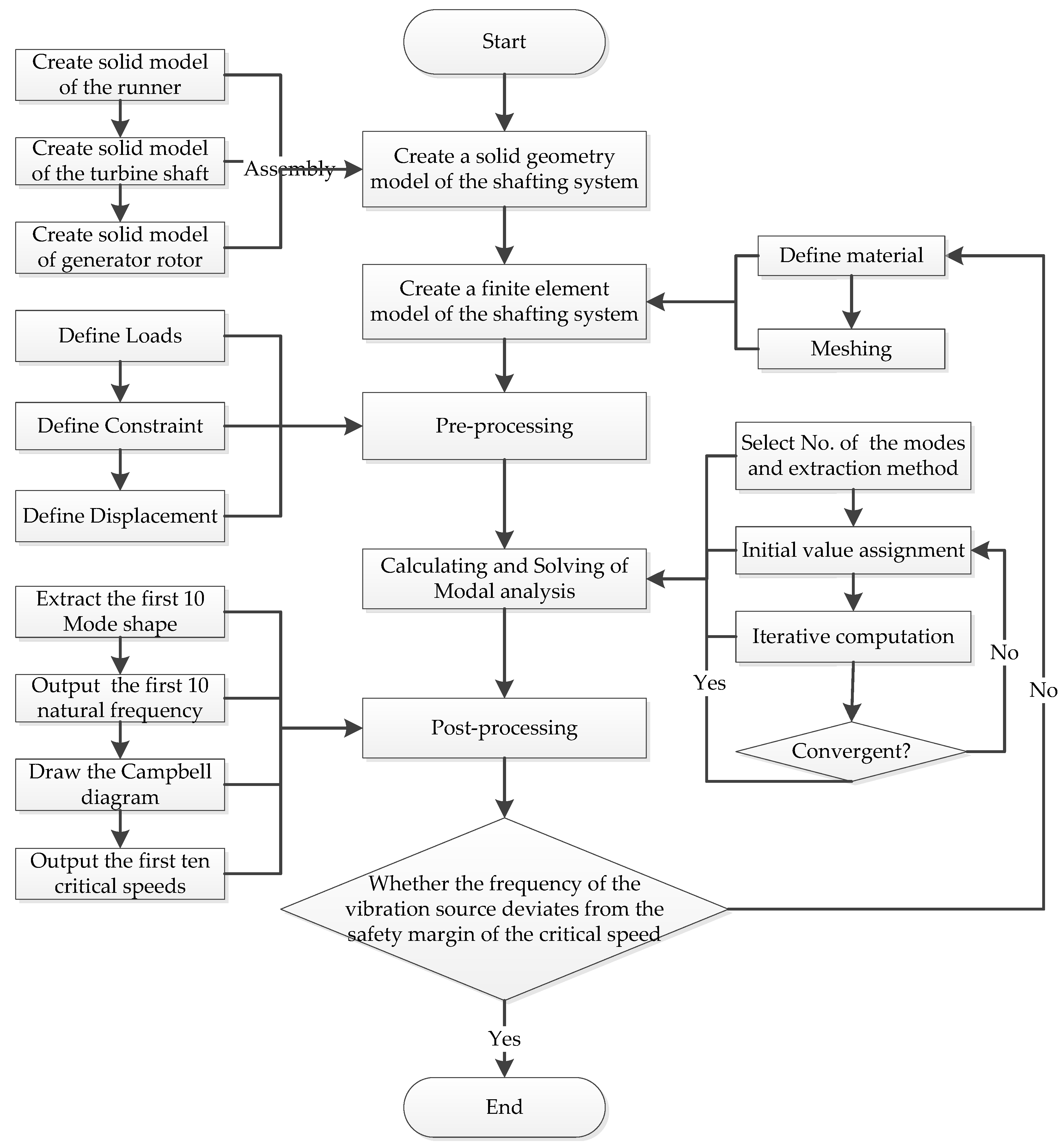
The finite element modal analysis to be adopted in this paper mainly includes the establishment of the solid geometric model of the shaft system, the establishment of the finite element calculation model, the pre-processing, the calculating and solving, the post-processing, the result analysis, the stability predicting and evaluating. The detailed flowchart is shown in Figure 1.
2.3.1. Establishing the Solid Geometric Model of the Shaft System
The shafting structure of the vertical Francis HGU is mainly composed of a generator rotor, generator shaft, turbine shaft, and runner. In the modeling process, the solid geometric model of each component of the shafting should be established first, and then assemble together to form the solid geometric model of the shaft system. In order to restore the prototype of the actual Unit as more as possible, the three-dimensional solid geometric model of the shafting is established based on the real design drawings of the studied case. Except for the necessary simplification required by the model establishing, the actual geometric dimensions are adopted in the model according to the design drawings.
2.3.2. Establishing a Finite Element Calculation Model
After the solid geometric model is established, the finite element calculation model should be established before calculating and solving of finite element modal analysis is carried out. The so-called finite element model refers to meshing the solid geometric model into small elements, so that it becomes a combination of many small elements and nodes. Therefore, the finite element model contains the data such as the number of nodes, node codes, node coordinates, and the number of elements and element codes. In addition, the boundary conditions, material properties, and external loads should also be taken into account. The quality of the finite element model is very important and should be evaluated after meshing, because it will directly affect the accuracy of the calculation results and the analysis efficiency.
Defining the material refers to determining the material’s physical and mechanical parameters of each component of the shaft system, such as elastic modulus, Poisson’s ratio, density, etc. The selection of their parameters plays an important role in the dynamic characteristics of the shaft system. The elastic modulus can be regarded as an index to measure the elastic deformation of a material. The larger the value, the greater the stress that causes the material to undergo a certain elastic deformation. In other words, the greater the stiffness of the material, the less elastic deformation under the action of a certain stress. The materials of each component of the shafting structure in this paper are also selected according to the real design drawings.
The meshing method used to discretize the solid geometric model can be divided into automatic meshing, semi-automatic meshing, and manual meshing. During meshing, it is necessary to define the type, size, and density of the elements. Generally speaking, for the same solid model, the denser the mesh division, the smaller the elements, and the more the nodes, and also the higher the accuracy of the numerical calculation results. However, the higher the accuracy requirement, the greater the requirement for the storage capacity of the computer, but the lower the calculation efficiency. Usually, in order to balance the calculation accuracy and efficiency, the mesh division needs to be encrypted only where the gradient of the domain variable is large, i.e., where the analysis data is large, such as the area where the stress is concentrated. In this paper, the automatic meshing of elements is adopted, and with it, the system will automatically select an optimized global control parameter to control the size and position of the tetrahedral elements, which could effectively divide the irregular structures into meshes and elements with different densities. By optimizing the meshing quality, it can not only ensure a certain calculation accuracy, but also improve the calculation efficiency.
2.3.3. Pre-Processing
The pre-processing mainly includes defining loads and defining boundary conditions. For the vertical HGU, the balance of the shafting is mainly realized by the axial-direction support of the thrust bearing as well as the radial-direction constraint provided by the upper guide bearing, the lower guide bearing, and the water guide bearing. Therefore, it is necessary to apply appropriate loads and boundary conditions onto the corresponding bearing positions of the shafting according to the actual working conditions of the Unit so as to constrain or release the corresponding axial-direction, radial-direction, or rotational degrees of freedom, and simulate the actual loading and constraining situation of the shafting.
2.3.4. Calculating and Solving
Currently, there are several methods for solving eigenvalues, such as matrix iteration method, Jocobi method, QL method, QR method, etc. with almost 7 methods for calculating and extracting the modes, i.e., Block Lanczos Method, Subspace Method, Power Dynamics Method, Reduced Method, Unsymmetric Method, Damped, QR Damped. Each method has its own advantages and applicable conditions, so an appropriate method needs to be selected according to the actual situation of the modal analysis. For example, the Block Lanczos Method is a very effective method for solving large sparse matrix eigenvalue, which is suitable for extracting a large number of mode shapes (more than 40 orders) of medium or large-scale models (with 5000-10000 degrees of freedom). It uses a set of eigenvectors to implement Lanczos iterative calculation, by which a sparse matrix is automatically used to solve the results directly with faster calculation speed. However, the subspace iteration method is very effective for extracting the first several order modes (below 40 orders) of large-scale models, which is suitable for models composed of relatively regular solid or shell elements. As long as the appropriate iteration accuracy and initial iteration vector are selected, the calculation accuracy is usually high without missing roots. Since this study intends to extract the first 10 order modes of the shaft system as analysis objects, the subspace iteration method is selected as the mode extraction method.
2.3.5. Post-Processing
Post-processing can display the calculation results more apparently in the form of color contour display, gradient display, vector display, particle flow trace display, three-dimensional slice display, transparent and semi-transparent display, etc. In addition, the calculation results can also be displayed or output in the form of charts and curves according to the requirements of the specific study and analysis. The results of the mode shapes in this paper will be displayed in the form of colored contour lines, and the natural frequencies and critical rotational speeds are output in the form of graphs.
3. Case Study
The case study selected in this paper is a newly built hydropower plant in Turkey. This project is installed with four vertical Francis Hydro generator Units with a unit capacity of 20.26 MW, which have been successfully put into commercial operation. The general introduction of the hydropower station is described as follows.
3.1. Basic Parameters of Hydraulic-Turbine Generator Unit
The basic parameters of the Hydraulic-Turbine Generator Unit are clearly described as shown in Table 1.
3.2. Shafting Composition and Geometric Dimensions
The shaft system of the HGU studied in this paper is composed of the generator rotor, the generator shaft, the hydraulic turbine shaft, the runner, and related important components. Among them, the generator rotor is assembled by several parts such as yoke, magnetic poles, lower guide bearing, thrust head, and mirror plate, while the runner is welded by the components such as an upper crown, blades, and lower ring. In order to make the solid geometric model as close to the prototype Unit as possible, each component of the shafting is kept with the actual structural distribution and size, and its main geometrical parameters are shown in Table 2.
3.3. Material Properties of Shaft Components
In the shafting structure, the material of the runner is stainless steel 06Cr13Ni4Mo. The materials of the turbine shaft, generator shaft, and the magnetic yoke are all forged steel 45A; while the material of the magnetic pole is composed of various materials, among which the coil material is braided by double-glass fiber wrapped flat copper wire, and pole core is laminated by silicon steel plates, so this study takes the material parameters of pure copper as a replacement of the magnetic pole for the sake of simplification. As for the rest, the thrust head material is casting steel ZG270-500, and the lower guide bearing is forged steel 35A. The materials’ physical and mechanical parameters of the main components of the shaft system are listed in Table 3.
3.4. Shafting’s Solid Geometry Modeling
According to the shafting composition and the actual dimension of each component shown in Table 2 and Table 3, it is at first to respectively establish the three-dimensional solid geometric model of each component of the shaft system, and then assemble them together in their relative positions, and finally, the solid geometric model of the shafting that is composed of runner, turbine shaft and generator rotor has been formed, as shown in Figure 2.
In the modeling process, according to the requirements of finite element analysis on the model of structural entity, and taking into account both the accuracy and economy of the calculation, the shaft system is appropriately simplified as follows: the rotor yoke is formed by multiple layers of steel plates laminated and bolted tightly together, which is replaced by a whole steel block stretched by a steel plate during modeling. The magnetic poles are mainly composed of the rotor armature core and the armature winding, the structure and material of which are very complex, so it is very difficult to accurately model them. However, these details have little influence on the dynamic characteristics of the overall structure of the shaft system, so the magnetic poles are simplified by 10 entity blocks that are stretched with pure copper material according to their actual shape and geometry dimensions. The turbine shaft and generator shaft have the same material and similar structure, which are connected by coupling bolts and used to transmit the torque. Therefore, they could be considered as a whole to be analyzed, and the shaft coupling zone can be treated as an integrated connection. The runner is a Francis type, the parts of which such as the blades, the upper crown, and the lower ring are connected as a whole by welding. When modeling, the welding place can also be treated as an integrated connection. In addition, some small fillets and chamfers, as well as small components such as screws and nuts in the solid model have little effect on the overall dynamic characteristics of the shaft system, so they are also simplified during modeling.
4. Result and Analysis
4.1. Material Defining and Meshing
The physical and mechanical properties of the materials of each component of the shafting have an important influence on the modal characteristics of the entire shafting. Before the calculation, the material parameters of each component of the shafting should be defined according to the physical and mechanical parameters listed in Table 3.
In this paper, the method of automatic meshing is used to discretize the entity model. Before meshing, it is necessary to define the type, size, and density of the elements. Then the system will automatically select an optimized global control parameter to control the size and position of the tetrahedral element, and meanwhile, the mesh is automatically encrypted where the gradient of the domain variable is large or the stress is concentrated such as runner, lower guide bearing and thrust bearing, etc. After meshing, the finite element calculation model of the shafting is generated, which contains a finite number of elements and nodes as shown in Figure 3, and its relevant meshing data of the model are shown in Table 4.
4.2. Boundary Conditions and Calculation Settings
The shaft system of the HGU is mainly constrained by its axial and radial degrees of freedom through three guide bearings and one thrust bearing. Among them, the water guide bearing and the upper and lower guide bearings of the generator constrain the radial swing and rotation of the shaft system respectively, that is, the radial displacement degree of freedom and the rotation degree of freedom around the corresponding coordinate axis, while the thrust bearing bears the weight of the entire shaft system and constrains the degree of freedom of axial displacement. Therefore, bearing constraints are given at the three guide bearings to constrain the radial displacement degrees of freedom and the rotational degrees of freedom around the shaft, while the axial displacement is constrained at the thrust bearings, and the rotational degrees of freedom around the shaft axis are released.
During the calculation, the prestress is not considered, but the influence of damping is considered, and then the first ten modes of the shafting are extracted and the natural frequency is calculated. To obtain the critical rotational speed of the shafting, five points of rotational velocity are selected to draw the Campbell diagram. Considering the constraints on the shafting, the rotational velocity at each point around the X, Y, and Z directions is shown in Table 5.
4.3. The First Ten-Order Mode Shapes
Through calculation and solution, the first ten-order modal analysis cloud diagram and mode shape of the shaft system are finally obtained as shown in Figure 4. The dashed shadow in each mode shape diagram represents the initial state of the rotor, and the relative displacement between the solid body and the dashed shadow represents the amplitude of the rotor in this mode.
It could be seen from the modal shape diagram of the shaft system that the first and second order modes represent the radial translation of the shaft system, the third and fourth order modes represent the oscillation of the shaft system, and the fifth and sixth orders are the bending deformation of the shaft system, the seventh order is the torsional deformation of the rotor, the eighth and ninth orders are the more complex continuous bending deformation of the shaft system, and the tenth order is the torsional deformation of the runner, and meanwhile, the amplitude of the bending and torsional deformation gradually increases with the increase of the order. That is to say, shafting has the changing laws of translation-oscillating-bending-torsion-more complex continuous bending and torsion. The higher the order, the more complex the bending and torsional deformation of the shafting. That is because the higher the order and the higher the natural frequency, the greater the exciting force required to cause resonance, and the greater the deformation amplitude caused by those forces acting on each structural element. In addition, because the mass and stiffness, loads and constraints, as well as boundary conditions of each component are usually different, which leads to different forced conditions and responses on each structure, so that the local displacement of the structural element is significantly different, thus it shows complex mode shapes on the macro.
In addition, the first four orders of the vibration mode of the shaft system are mainly regarded as rigid body modes with very low natural frequencies, while the subsequent modes are regarded as elastic modes. This is mainly because the rigid body in space has six degrees of freedom, respectively for three translational and three rotational degrees of freedom. An elastic continuum actually has an infinite number of degrees of freedom, but the finite element analysis makes the continuous infinite number of degrees of freedom subject discretized into a finite number of degrees of freedom subject. Thus, the degrees of freedom of the structure are also finite [36]. In this paper, the translational and rotational degrees of freedom in the Y direction are constrained by the setting of boundary conditions, so the first four-order rigid body modes are mainly represented as translation and oscillation along the X and Z directions, which conforms to the fundamental theory. However, for a structural system with a free boundary, not only the elastic mode but also the rigid body mode are required to fully describe its dynamic characteristics [37]. Nevertheless, in the testing process of practical engineering, the rigid body modes are always ignored and not considered as a part of the elastic mode, so it is difficult to obtain the rigid body mode of the structure. In this paper, the rigid body mode of the shaft system can be directly restored through numerical calculation and finite element modal analysis, which conforms to the inherent dynamic characteristics of the rotational structure.
4.4. The First Ten Order Natural Frequency and Critical Speed
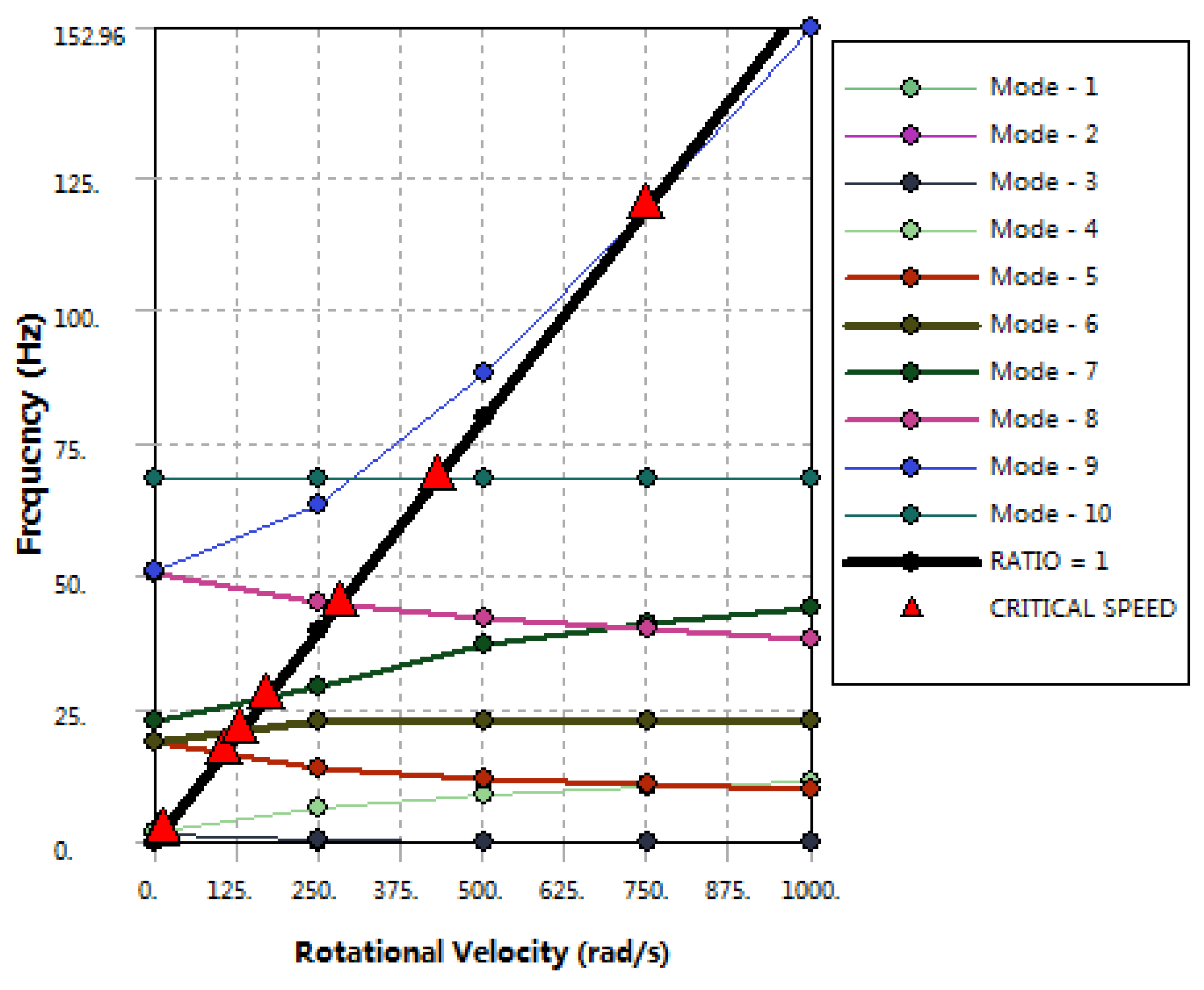
According to the given velocity point and the calculated natural frequencies of each order, a Campbell diagram is drawn, in which the abscissa is the rotational velocity, and the ordinate is the frequency. The velocity-frequency curve is obtained as shown in Figure 5. The intersection of the velocity-frequency curve of each order and a straight line with a slope of 1 is the critical speed point of the mode, i.e., the velocity corresponding to the intersection is the critical speed. Table 6 gives the first ten order natural frequencies and critical speeds of the shafting.
The critical speed of the rotating shafting refers to the speed when the value is equal to the natural frequency of the shafting, that is, the speed when resonance occurs. The shaft system of the HGU is subjected to various vibration exciting sources during operation. If the frequency of a certain vibration exciting source is equal to the natural vibration frequency of the shaft system, the shaft system would be likely to resonate. In order to avoid the harm caused by resonance, it is so necessary to calculate and analyze the critical speed of the shafting so that the working speed of the HGU could be kept away from the critical speed, so as to avoid resonance.
It can be found from Table 6 that the natural frequencies of the first four-order rigid body modes of the shaft system are very low at any rotational velocity, while from the fifth-order elastic mode, the critical speed of the shaft system increases gradually with the increase of modal order. Usually, the elastic mode of the structural system is the common cause of all vibration and noise problems. Therefore, in the structural design of the shaft system, the rated working speed of the shaft system is normally required to be lower than the first-order critical speed of the elastic mode, or the intermediate value between the first-order critical speed and the second-order critical speed. In addition, in order to ensure that the structure does not resonate within the range of working speed, the structural design of the shaft system should meet the requirement that the working speed should deviate from the critical speed with a safety margin of at least 15%~25% [38].
The rated speed of the shafting studied in this paper is 600 r/min according to Table 1, i.e., 62.80 rad/s, while the first-order critical speed of the elastic mode (corresponding to the fifth-order mode in Table 6, the same as below) is 104.45 rad/s. Therefore, the safety margin of the rated working speed deviating from the critical speed is 39.9%, which fully meets the natural vibration characteristics requirements of the structural design, so the shaft system of the HGU could operate stably at the rated speed, and resonance could not occur due to the rotational frequency.
However, the runaway speed of the Unit is 1064 r/min, i.e., 111.37 rad/s, which is between the first-order critical speed of 104.45 rad/s and the second-order critical speed of 130.21 rad/s (corresponding to the sixth-order mode in Table 6). When the working condition of runaway occurs, the Unit needs to cross the first-order critical speed, and the safety margin of the runaway speed deviating from the first-order critical speed is too small, only 6.6%, thus there would be the possibility of the resonance due to rotational frequency. Therefore, this kind of situation should be prevented during the structural design of the shafting.
The critical speed is mainly related to some factors such as the elasticity and mass distribution of the shaft system. For a discretized rotating system with a finite number of lumped masses, the number of critical speeds is equal to the number of lumped masses; while for an elastic rotating system with continuous mass distribution, there are infinitely many critical speeds, and their magnitude is positively related to the elasticity of the shafting [39]. Therefore, in view of the problem mentioned hereinbefore that resonance is likely to be caused by crossing the first-order critical speed of the elastic mode when the Unit is a runaway, materials with larger elastic modulus are proposed to be selected during the optimal design of the shafting structure so as to increase the stiffness of the shafting, which makes the natural frequency of the first-order elastic mode of the shafting moved up and meanwhile the first-order critical speed is also increased accordingly. In this way, the runaway speed would be always lower than the first-order critical speed and maintains a certain safety margin. In addition, it can also be considered to improve the mass distribution of the shafting structure during structural design to make the overall mass distribution more balanced.
5. Conclusions
In this paper, the finite element modal analysis and numerical calculation have been carried out to predict and analyze the shafting vibration of HGU in the actual engineering application, and the natural vibration characteristics and mode shapes of the shaft system have been obtained. Meanwhile, the natural frequency of the shafting and its critical speed have been also calculated. By analyzing the calculation results, the following conclusions could be drawn as follows:
- (1)
- The mode shapes of the shaft system from low order to high order is a process of change from simple to complex, and generally represent a certain change law starting from translation, swing, bending, and torsion, to complex continuous bending and torsion. The higher the mode order, the more complex the bending and torsional deformation of the shafting.
- (2)
- In practical engineering testing, only the elastic mode of the shaft structure is usually considered, while the rigid body mode is ignored. In this paper, the rigid body mode of the shaft system is restored through numerical calculation, which can completely describe the modal characteristics of the shaft system in theory.
- (3)
- Through the analysis of the critical speed, it can be discovered that the shaft system of the studied case could not cause resonance due to the rotational frequency when it operates at the rated speed, but when the Unit has a runaway accident, there would be a possibility of resonance caused by the rotational frequency.
- (4)
- In view of the structural design of the shaft system, some measures for structural optimization design are proposed by means of this predictive analysis method: one is increasing the stiffness of the shaft system, thereby increasing the critical speed, and making the runaway speed lower than the first-order critical speed and maintaining a certain safety margin. The other is improving the mass distribution of the shafting structure to make it more balanced.
6. Patents
The paper reports the real-world application of a pending invention patent in China (Patent No.: 202210736064.2).
Author Contributions
Conceptualization, W.W. and Y.S.; methodology, Y.S.; software, W.W. and Z. Y; validation, W.W.; formal analysis, Z.Y.; investigation, W.W.; resources, Y.S.; data curation, Z.Y.; writing—original draft preparation, W.W.; writing—review and editing, Y.S.; visualization, W.W., Z.Y; supervision, Y.S.; project administration, Y.S.; funding acquisition, Y.S. All authors have read and agreed to the published version of the manuscript.
Funding
This research was funded by Beijing Natural Science Foundation under grant No. JQ21029 and the APC was funded by it.
Data Availability Statement
The data presented in this study are available on request from the corresponding author. The data are not publicly available due to privacy or ethical restrictions.
Acknowledgments
In this section, Zeyang Zhao from North China University of Water Resources and Electric Power for doing a lot on the collection and collation of the relevant information and data.
Conflicts of Interest
The authors declare no conflict of interest.
References
- Xu, Y. Dynamic Modeling and Simulation Analysis of Shafting System of Large-Scale Hydro-Generator Set. Ph.D. Thesis, Huazhong University of Science and Technology, Wuhan, China, 2012. [Google Scholar]
- Peng, X.L. Research on Vibration Characteristics of Hydroelectric Units Based on Hydroelectric Multifield Coupling Finite Element Method. Ph.D. Thesis, Huazhong University of Science and Technology, Wuhan, China, 2018. [Google Scholar]
- Chu, S.; Majumdar, A. Opportunities and challenges for a sustainable energy future. Nature 2012, 488, 294–303. [Google Scholar] [CrossRef] [PubMed]
- Song, Z.Q.; Ma, Z.Y. Coupling Vibration Test and Finite Element Numerical Feedback Calculation of Unit and Powerhouse of Hydropower Station. J. Hydroelectr. Eng. 2012, 31, 170–174. [Google Scholar]
- Xu, W.; Ma, Z.Y. Study of the Vibration Transmission and Path Recognition of an Underground Powerhouse Using Energy Finite Element Method. Shock. Vib. 2016, 2016, 5039578. [Google Scholar] [CrossRef]
- Leonov, G.A.; Kuznetsov, N.V.; Solovyeva, E.P. Mathematical modeling of vibrations in turbogenerator sets of Sayano-Shushenskaya Hydroelectric Power Station. Dokl. Phys. 2016, 61, 55–60. [Google Scholar] [CrossRef]
- Qu, L.T.; Zhou, Y. Research on Typical Rotor Dynamics Problems of Hydrogenerator Sets. Large Electr. Mach. Hydraul. Turbine 2020, 2020, 24–28. [Google Scholar]
- Liang, X.D. Research on Operation Stability of Large-scale Hydro-generator Units. Mech. Electr. Inf. 2016, 2016, 27–28. [Google Scholar]
- Zheng, Z.L.; Xie, Y.G.; Zhang, D.; Ye, X.L. Effects of Stator Stiffness, Gap Size, Unbalance, and Shaft’s Asymmetry on the Steady-State Response and Stability Range of an Asymmetric Rotor with Rub-Impact. Shock. Vib. 2019, 8, 1–11. [Google Scholar] [CrossRef]
- Zhou, J.Z.; Peng, X.L.; Peng, X.L.; Li, R.H.; Xu, Y.H.; Liu, H.; Chen, D.Y. Experimental and Finite Element Analysis to Investigate the Vibration of Oblique-Stud Stator Frame in a Large Hydropower Generator Unit. Energies 2017, 10, 2175. [Google Scholar] [CrossRef]
- Xu, B.B.; Chen, D.Y.; Zhang, H.; Li, C.H.; Zhou, J.Z. Shaft mis-alignment induced vibration of a hydraulic turbine generating system considering parametric uncertainties. J. Sound Vib. 2018, 435, 74–90. [Google Scholar] [CrossRef]
- Dal, A.; Karaçay, T. Effects of angular misalignment on the performance of rotor-bearing systems supported by externally pressurized air bearing. Tribol. Int. 2017, 111, 276–288. [Google Scholar] [CrossRef]
- Bai, B.; Zhang, L.X.; Zhao, L. Influence of guide bearing stiffness on natural vibration characteristics of turbine shafting. Chinese Journal of Drainage and Irrigation Machinery. J. Drain. Irrig. Mach. Eng. 2013, 31, 318–324. [Google Scholar]
- Xu, B.B.; Luo, X.Q.; Egusquiza, M.; Ye, W.; Liu, J.; Egusquiza, E. Nonlinear modal interaction analysis and vibration characteristics of a francis hydro-turbine generator unit. Renew. Energy 2021, 168, 854–864. [Google Scholar] [CrossRef]
- Paturu, P.; Vinoth Kanna, I.; Mallela, G. A detailed analysis of free vibration on 70 MW hydro power turbine rotor. Int. J. Ambient. Energy 2019, 42, 880–887. [Google Scholar] [CrossRef]
- Sun, W.Q.; Guo, Z.Q. Mathematical modeling and nonlinear vibration analysis of a coupled hydro-generator shaft-foundation system. Commun. Nonlinear Sci. Numer. Simul. 2021, 98, 105776. [Google Scholar] [CrossRef]
- Li, M.M.; Li, Z.; Ma, L.L.; Zhu, R.P.; Ma, X.Z. Effect of the Supports’ Positions on the Vibration Characteristics of a Flexible Rotor Shafting. Shock. Vib. 2020, 2020, 1592794. [Google Scholar] [CrossRef]
- Zhuang, K.Y.; Gao, C.D.; Li, Z.; Yan, D.L.; Fu, X.Q. Dynamic Analyses of the Hydro-Turbine Generator Shafting System Considering the Hydraulic Instability. Energies 2018, 11, 2862. [Google Scholar] [CrossRef]
- Wang, J.; Song, Z.Q.; Liu, Y.J. Analysis of Shaft System Vibration of Hydroelectric Unit Based on Reasonable Application of Hydraulic Vibration Source. J. Water Resour. Water Eng. 2018, 29, 188–195. [Google Scholar]
- Song, Z.Q.; Liu, Y.H.; Guo, P.C.; Feng, J.J. Torsional Vibration Analysis of Hydro-Generator Set Considered Electromagnetic and Hydraulic Vibration Resources Coupling. Int. J. Precis. Eng. Manuf. 2018, 19, 939–945. [Google Scholar] [CrossRef]
- Ma, H.; Wang, X.L.; Niu, H.Q.; Wen, B.C. Oil-film instability simulation in an overhung rotor system with flexible coupling misalignment. Arch. Appl. Mech. 2015, 85, 893–907. [Google Scholar] [CrossRef]
- Kim, J.W.; Kwak, W.I.; Choe, B.S.; Kim, H.H.; Suh, S.H.; Lee, Y.B. The rotor dynamic analysis of the vibration considering the hydro-electric force supported by rolling elements in 500 kW Francis turbine. J. Mech. Sci. Technol. 2017, 31, 5153–5159. [Google Scholar] [CrossRef]
- Keller, S.; Xuan, M.T.; Simond, J.J.; Schwery, A. Large low-speed hydro-generators–unbalanced magnetic pulls and additional damper losses in eccentricity conditions. IET Electr. Power Appl. 2007, 1, 657–664. [Google Scholar] [CrossRef]
- Zarko, D.; Ban, D.; Vazdar, I.; Jarica, V. Calculation of Unbalanced Magnetic Pull in a Salient-Pole Synchronous Generator Using Finite-Element Method and Measured Shaft Orbit. IEEE Trans. Ind. Electron. 2012, 59, 2536–2549. [Google Scholar] [CrossRef]
- Xu, X.P.; Han, Q.K.; Chu, F.L. Nonlinear vibration of a generator rotor with unbalanced magnetic pull considering both dynamic and static eccentricities. Arch. Appl. Mech. 2016, 86, 1521–1536. [Google Scholar] [CrossRef]
- He, Y.L.; Sun, Y.X.; Xu, M.X.; Wang, X.L.; Wu, Y.C.; Vakil, G.; Gerada, D.; Gerada, C. Rotor UMP characteristics and vibration properties in synchronous generator due to 3D static air-gap eccentricity faults. IET Electr. Power Appl. 2020, 14, 961–971. [Google Scholar] [CrossRef]
- Mahdi, K.; Korosh, K.; Rossana, D.; Francesco, T. Size-dependent hydroelastic vibration of FG microplates partially in contact with a fluid. Compos. Struct. 2020, 244, 112320. [Google Scholar]
- Lai, X.D.; Zhu, Y.; Liao, G.L.; Zhang, X.; Wang, T.; Zhang, W.B. Lateral Vibration Response Analysis on Shaft System of Hydro Turbine Generator Unit. Adv. Vib. Eng. 2013, 12, 511–524. [Google Scholar]
- Li, R.H.; Li, C.S.; Peng, X.L.; Wei, W. Electromagnetic Vibration Simulation of a 250-MW Large Hydropower Generator with Rotor Eccentricity and Rotor Deformation. Energies 2017, 10, 2155. [Google Scholar] [CrossRef] [Green Version]
- Song, Z.Q.; Ma, Z.Y. Torsional vibration analysis of shaft system of hydroelectric unit considering hydraulic and electromagnetic excitation. J. Hydroelectr. Eng. 2012, 31, 240–245. [Google Scholar]
- Bai, B.; Zhang, L.X.; Guo, T.; Liu, C.Q. Analysis of dynamic characteristics of the main shaft system in a hydro-turbine based on ANSYS. Procedia Eng. 2012, 31, 654–658. [Google Scholar] [CrossRef]
- Zhu, C.X.; Wang, D.Y.; Zhu, C.Q.; Wang, X.W. Comparative analysis of transfer matrix method and finite element method to calculate the critical speed of motor rotor. Electr. Mach. Control. Appl. 2015, 2015, 57–60. [Google Scholar]
- Zhou, W.J.; Wei, X.S.; Wu, G.K.; Liu, W.J.; Wang, L.Q. Numerical research on dynamic lateral vibration of a pump-turbine’s shaft system. J. Eng. Res. 2015, 3, 127–148. [Google Scholar] [CrossRef]
- Niu, L.T.; Su, Q.; Ma, C.Y.; Liao, J.L.; Pu, J.G. Research on Modal Analysis of Rotor Shaft System of Hydro-generator. J. Phys. Conf. Ser. 2020, 1549, 042084. [Google Scholar] [CrossRef]
- Yang, G.B.; Zeng, Y.; Zhang, J.K.; Wang, F.F.; Zhang, Z.K.; Qian, J. Approximate calculation method for shafting stiffness of hydro-generator set. J. Drain. Irrig. Mach. Eng. 2020, 38, 787–793. [Google Scholar]
- Yang, G.B.; Zeng, Y.; Zhang, J.K. Modal analysis of eccentric shaft system of hydro-generator rotor based on finite element method. Water Resour. Power 2019, 37, 119, 136–138. [Google Scholar]
- Huang, Z.H.; Xie, Y.; Deng, Y.; Gao, H.W. Shafting Modal Analysis of Hybrid Excavator Power System. Constr. Mach. Equip. 2012, 43, 25–28. [Google Scholar]
- Knight, J.D.; Plaut, R.H.; Virgin, L.N. A New Method for Predicting Critical Speeds in Rotor dynamics. J. Eng. Gas Turbines Power 2016, 138, 022504. [Google Scholar]
- Murav’ev, O.A. Torsional Vibrations of the Rotating Parts of a Hydroelectric Generating Set in Transient Processes of Hydroelectric Power Plants. Power Technol. Eng. 2019, 52, 548–551. [Google Scholar] [CrossRef]
Figure 1.
Flow chart of Finite element modal analysis method.

Figure 2.
Solid geometry model of Shafting system.

Figure 3.
Finite element model of the Shafting system.

Figure 4.
Modal shapes of the first ten order modes.

Figure 5.
Campbell diagram.


Table 1.
Basic parameters of the Hydraulic-Turbine Generator Unit.
| Hydro-Turbine | Generator | ||
|---|---|---|---|
| Type | Francis | Rated power | 20,265 kw |
| Rated water head | 181.26 m | Rated voltage | 10,600 V |
| Rated flow rate | 12.5 m3/s | Rated current | 1298.6 A |
| Rated power | 20,892 kW | Rated frequency | 50 Hz |
| Runner diameter | 1430 mm | Rated rotational speed | 600 r/min |
| Moment of inertia | ≥110 ton∙m2 | Runaway speed | 1064 r/min |
Table 2.
Shafting composition and main geometric parameters of the HGU.
| Shafting System | Parts | Dimension | Unit |
|---|---|---|---|
| Generator rotor | Rotor height | 5342 | mm |
| Rotor diameter | 2510 | mm | |
| Trust bearing height | 770 | mm | |
| No. of Magnetic pole | 10 | Pcs. | |
| Turbine shaft | Height | 2805 | mm |
| Runner | Runner diameter | 1430 | mm |
| Runner height | 625 | mm | |
| No. of Blade | 15 | Pcs. |
Table 3.
Materials’ physical and mechanical parameters of shafting components.
| Main Parts | Material | Elastic Modulus (MPa) | Poisson’s Ratio | Density (kg/m3) |
|---|---|---|---|---|
| Runner | Stainless Steel (06Cr13Ni4Mo) | 210,000 | 0.3 | 7.90 × 10³ |
| Shaft | Forged steel (45A) | 209,000 | 0.269 | 7.89 × 10³ |
| Magnetic yoke | Forged steel (45A) | 209,000 | 0.269 | 7.89 × 10³ |
| Magnetic pole | Various materials (use Copper instead) | 110,000 | 0.32 | 8.85 × 10³ |
| Thrust bearing | Casting steel (ZG270-500) | 202,000 | 0.3 | 7.80 × 10³ |
| Mirror plate | Forged steel (45A) | 209,000 | 0.269 | 7.89 × 10³ |
Table 4.
Shafting geometry, physics, and meshing.
| Computational Domain | Physical Characteristics | Mesh | |||
|---|---|---|---|---|---|
| X-axis | 2.4830 m | Volume | 7.1741 m³ | Components | 19 |
| Y-axis | 8.7600 m | Weight | 56,362 kg | Nodes | 59,022 |
| Z-axis | 2.4926 m | Scale | 1:1 | Elements | 28,879 |
Table 5.
Shafting rotational velocity for Campbell diagram.
| Rotational Velocity | X (rad/s) | Y(rad/s) | Z (rad/s) |
|---|---|---|---|
| 1 | 0 | 0 | 0 |
| 2 | 0 | 250 | 0 |
| 3 | 0 | 500 | 0 |
| 4 | 0 | 750 | 0 |
| 5 | 0 | 1000 | 0 |
Table 6.
The first ten natural frequencies and critical speeds.
| Mode | Critical Speed | 0 rad/s | 250 rad/s | 500 rad/s | 750 rad/s | 1000 rad/s |
|---|---|---|---|---|---|---|
| 1 | NONE | 0 Hz | 0 Hz | 0 Hz | 0 Hz | 0 Hz |
| 2 | NONE | 2.2 × 10⁻⁴ Hz | 2.2 × 10⁻⁴ Hz | 2.223 × 10⁻⁴ Hz | 2.2 × 10⁻⁴ Hz | 2.2 × 10⁻⁴ Hz |
| 3 | 9.359 rad/s | 1.5345 Hz | 0.33331 Hz | 0.17165 Hz | 0.1151 Hz | 8.6498 × 10⁻² Hz |
| 4 | 13.257 rad/s | 1.8555 Hz | 6.6546 Hz | 9.1421 Hz | 10.485 Hz | 11.458 Hz |
| 5 | 104.45 rad/s | 18.669 Hz | 13.774 Hz | 11.866 Hz | 10.795 Hz | 10.033 Hz |
| 6 | 130.21 rad/s | 18.754 Hz | 22.536 Hz | 22.536 Hz | 22.536 Hz | 22.536 Hz |
| 7 | 169.81 rad/s | 22.536 Hz | 29.146 Hz | 36.915 Hz | 41.121 Hz | 43.9 Hz |
| 8 | 281.48 rad/s | 50.433 Hz | 45.178 Hz | 42.163 Hz | 39.947 Hz | 38.233 Hz |
| 9 | 748.44 rad/s | 50.796 Hz | 63.473 Hz | 88.105 Hz | 119.31 Hz | 152.96 Hz |
| 10 | 428.76 rad/s | 68.237 Hz | 68.24 Hz | 68.238 Hz | 68.244 Hz | 68.251 Hz |
Publisher’s Note: MDPI stays neutral with regard to jurisdictional claims in published maps and institutional affiliations. |
© 2022 by the authors. Licensee MDPI, Basel, Switzerland. This article is an open access article distributed under the terms and conditions of the Creative Commons Attribution (CC BY) license (https://creativecommons.org/licenses/by/4.0/).
Share and Cite
MDPI and ACS Style
Wang, W.; Shang, Y.; Yao, Z. A Predictive Analysis Method of Shafting Vibration for the Hydraulic-Turbine Generator Unit. Water 2022, 14, 2714. https://doi.org/10.3390/w14172714
AMA Style
Wang W, Shang Y, Yao Z. A Predictive Analysis Method of Shafting Vibration for the Hydraulic-Turbine Generator Unit. Water. 2022; 14(17):2714. https://doi.org/10.3390/w14172714
Chicago/Turabian StyleWang, Wuchang, Yizi Shang, and Zhifeng Yao. 2022. "A Predictive Analysis Method of Shafting Vibration for the Hydraulic-Turbine Generator Unit" Water 14, no. 17: 2714. https://doi.org/10.3390/w14172714
Note that from the first issue of 2016, this journal uses article numbers instead of page numbers. See further details here.