Experimental Study on the Fracturing Behaviors and Mechanical Properties of Cracks under Coupled Hydro-Mechanical Effects in Rock-like Specimens

Abstract
:1. Introduction
2. Materials and Methods
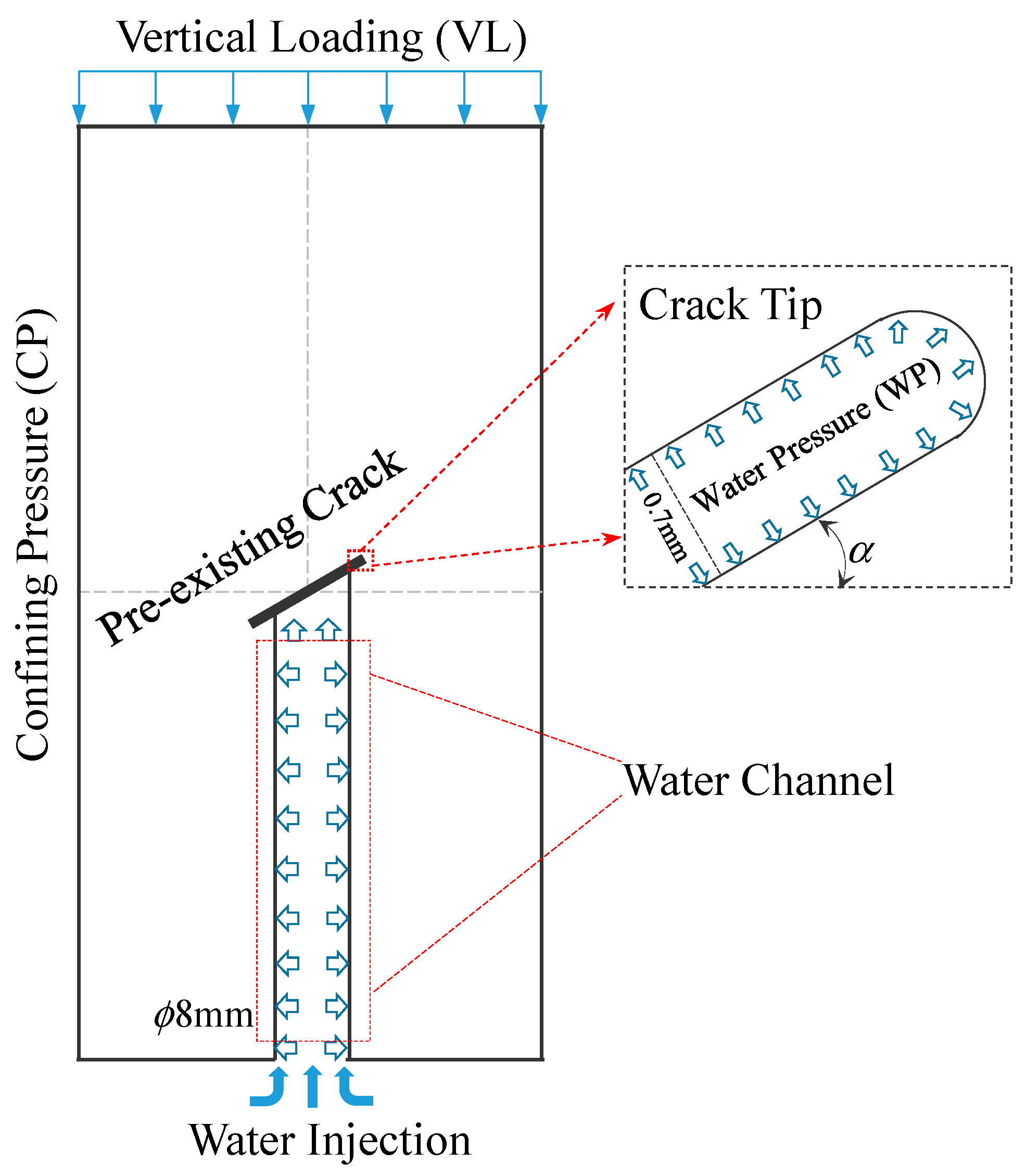
2.1. Specimen Preparation
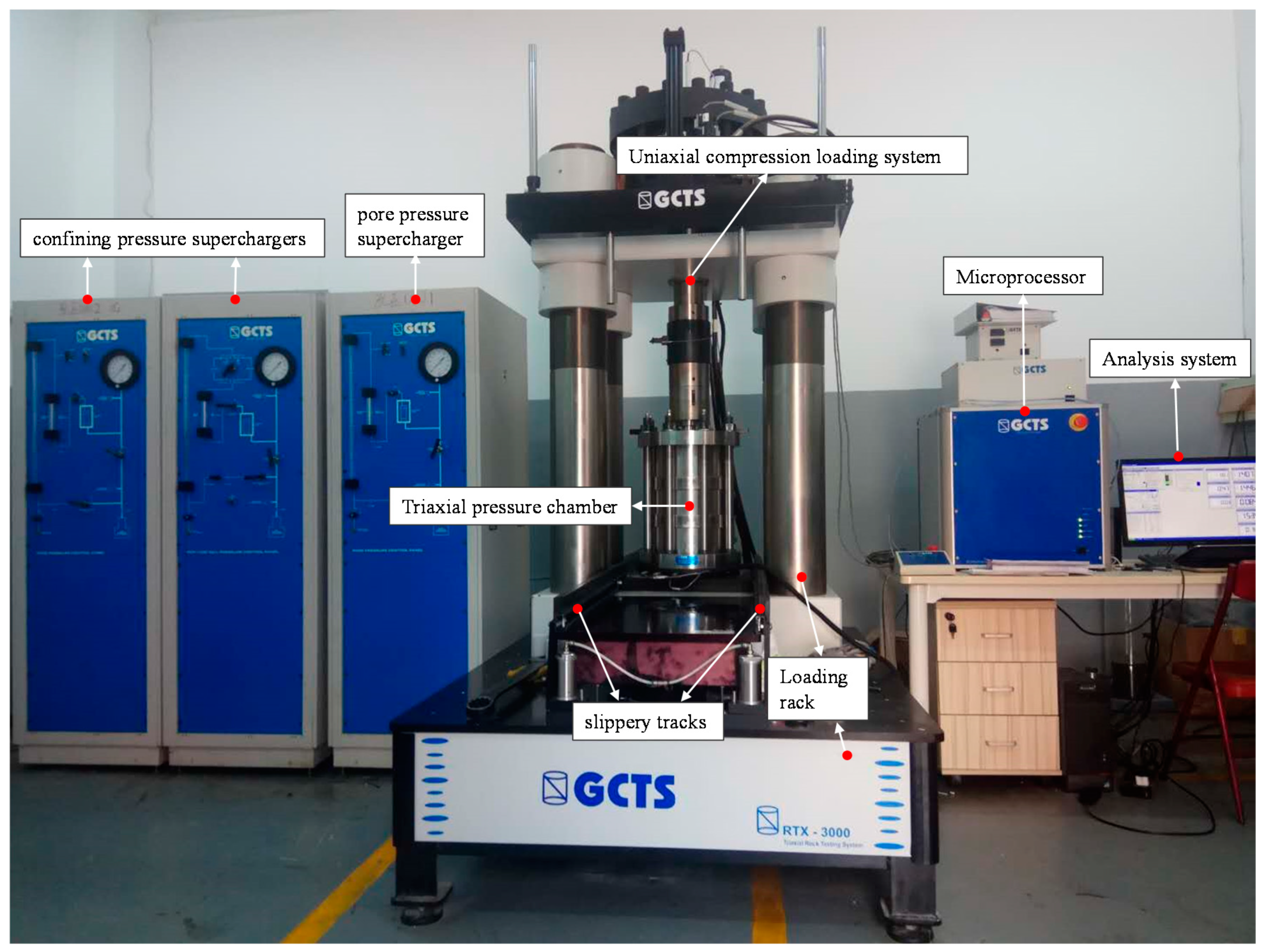
2.2. Test Setup and Procedures
3. Macroscopic Study
3.1. Trajectories of Dry Cracks
3.2. Trajectories of Dry Cracks
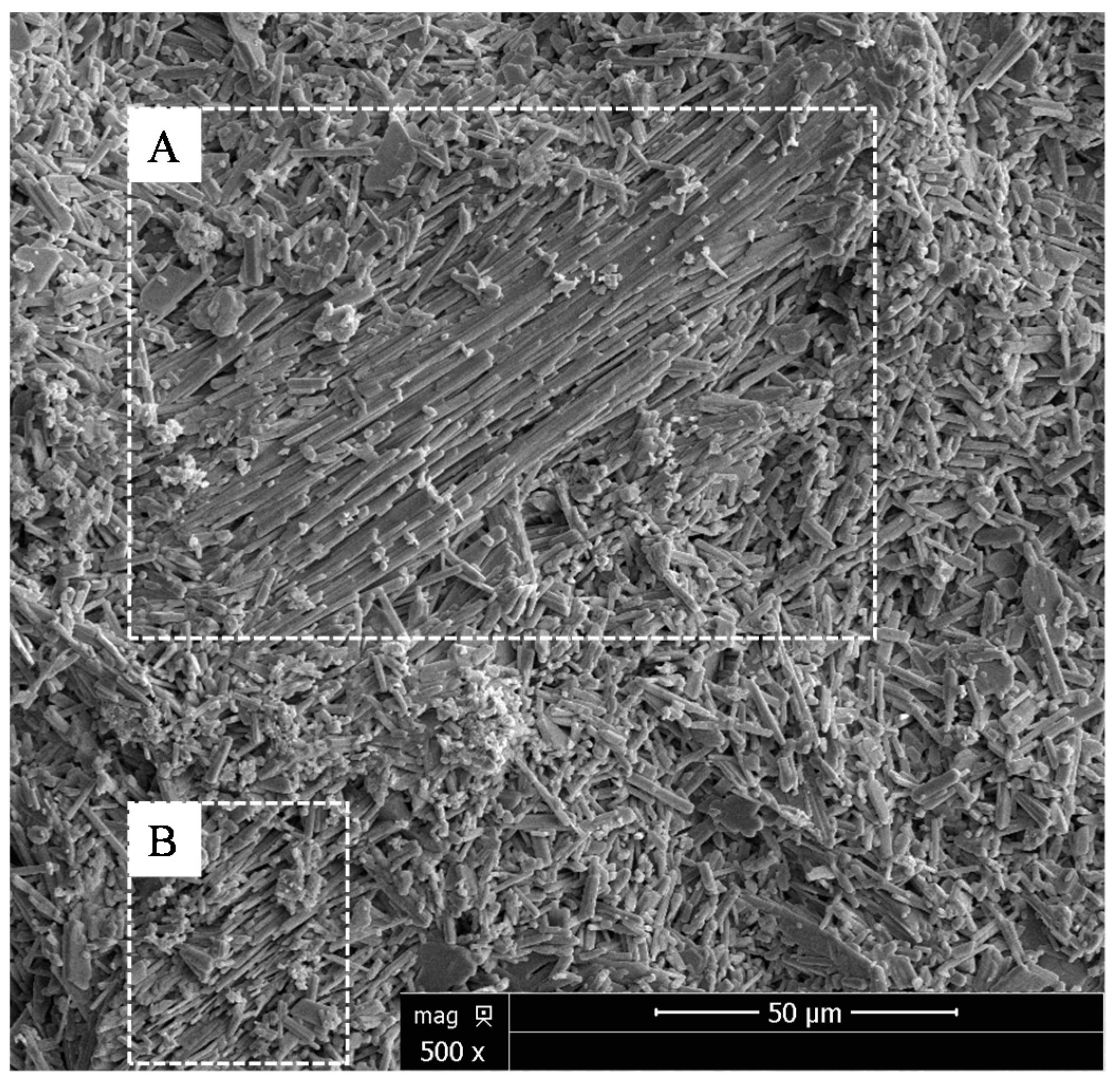
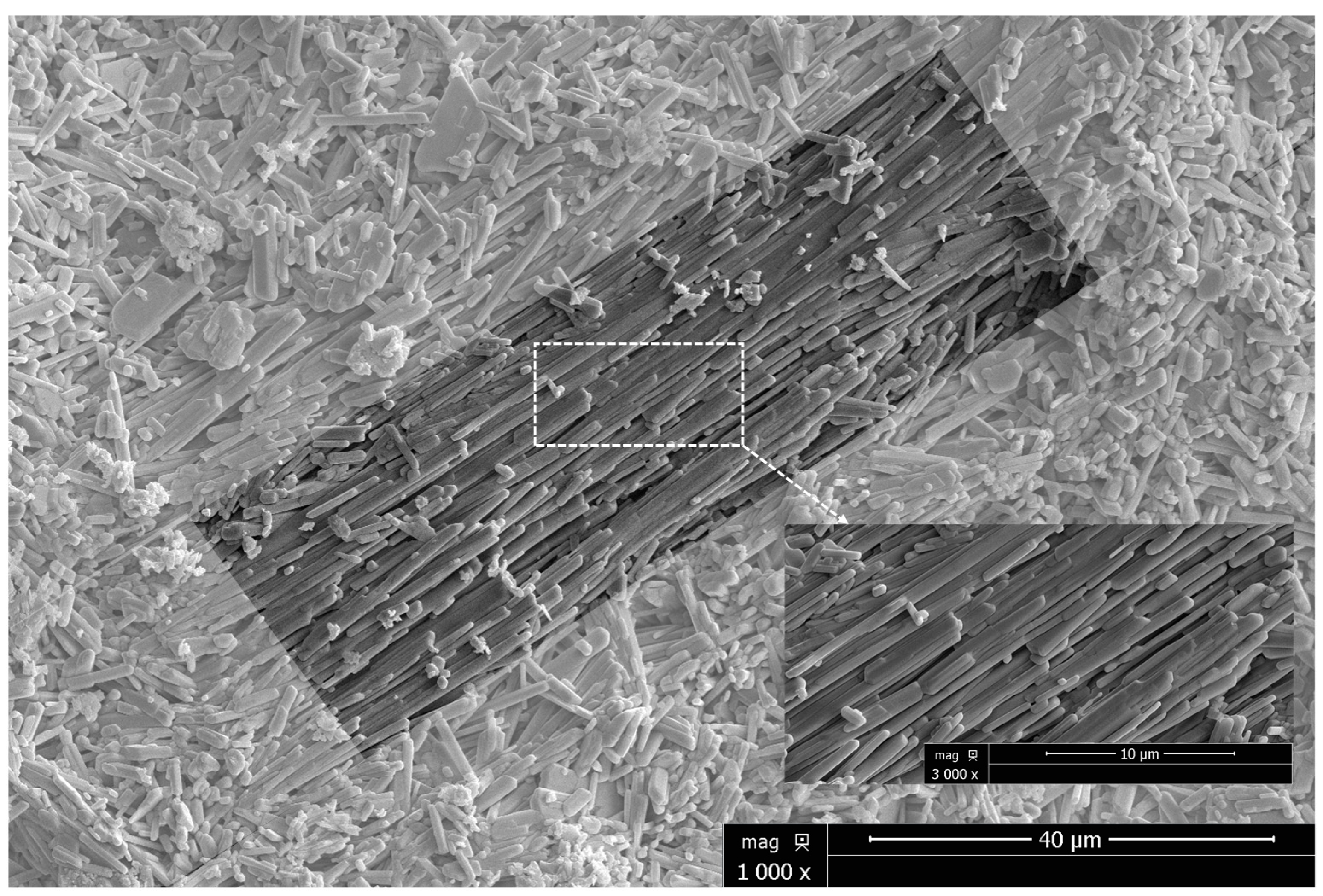
4. Microscopic Study
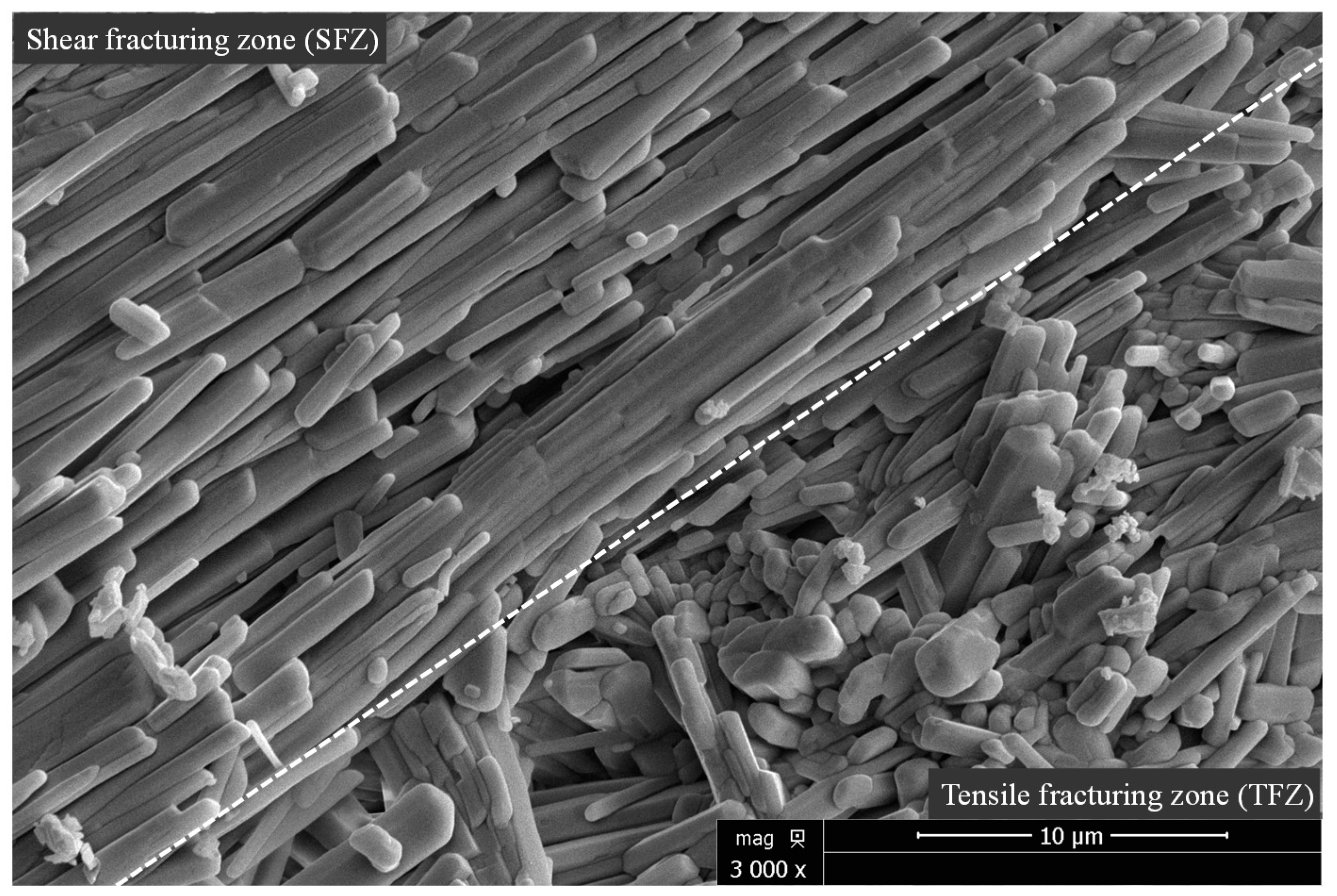
4.1. Shear and Tensile Fracturing Zones
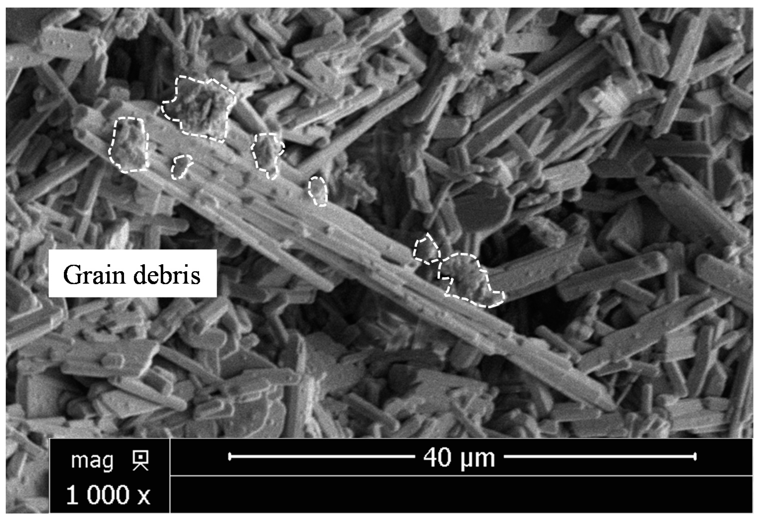
4.2. Mechanical Properties of HCC
5. Conclusions
Author Contributions
Funding
Conflicts of Interest
References
- Gonçalves da Silva, B.; Einstein, H.H. Physical processes involved in the laboratory hydraulic fracturing of granite: Visual observation and interpretation. Eng. Fract. Mech. 2018, 191, 125–142. [Google Scholar] [CrossRef]
- Warpinsky, N.R.; Clark, J.A.; Schmidt, R.A.; Huddle, C.W. Laboratory investigation on the effect of in-situ stresses on hydraulic fracture containment. Soc. Pet. Eng. J. 1982, 22, 333–340. [Google Scholar] [CrossRef]
- Song, I.; Suh, M.; Won, K.S. A laboratory study of hydraulic fracturing breakdown pressure in table rock sandstone. Geosci. J. 2001, 5, 263–271. [Google Scholar] [CrossRef]
- Stanchits, S.; Mayr, S.; Shapiro, S.; Dresen, G. Fracturing of porous rock induced by fluid injection. Tectonophysics 2011, 503, 129–145. [Google Scholar] [CrossRef]
- Li, B.; Wong, R.C.K.; Milnes, T. Anisotropy in capillary invasion and fluid flow through induced sandstone and shale fractures. Int. J. Rock Mech. Min. 2014, 65, 129–140. [Google Scholar] [CrossRef]
- Guo, C.; Xu, J.; Wei, M.; Jiang, R. Experimental study and numerical simulation of hydraulic fracturing tight sandstone reservoirs. Fuel 2015, 159, 334–344. [Google Scholar] [CrossRef]
- Zhao, J.; Pu, X.; Li, Y.; He, X. A semi-analytical mathematical model for predicting well performance of a multistage hydraulically fractured horizontal well in naturally fractured tight sandstone gas reservoir. J. Nat. Gas Sci. Eng. 2016, 32, 273–291. [Google Scholar] [CrossRef]
- He, J.M.; Lin, C.; Li, X.; Zhang, Y.; Chen, Y. Initiation, propagation, closure and morphology of hydraulic fractures in sandstone cores. Fuel 2017, 208, 65–70. [Google Scholar] [CrossRef]
- Rodriguez, I.V.; Stanchits, S. Spatial and temporal variation of seismic attenuation during hydraulic fracturing of a sandstone block subjected to triaxial stress. J. Geophys. Res. Solid Earth 2017, 122, 9012–9030. [Google Scholar] [CrossRef]
- Warpinski, N.R.; Teufel, L.W. Influence of geologic discontinuities on hydraulic fracture propagation. J. Pet. Technol. 1987, 39, 209–220. [Google Scholar] [CrossRef]
- Blair, S.C.; Thorpe, R.K.; Heuze, F.E.; Shaffer, R.J. Laboratory observations of the effect of geological discontinuities on hydrofracture propagation. In Proceedings of the 30th US Symposium on Rock Mechanics, Morgantown, WV, USA, 19–22 June 1989; pp. 433–450. [Google Scholar]
- Damani, A.; Sharma, A.; Sondergeld, C.H.; Rai, C.S. Acoustic mapping and microscopic analysis of laboratory induced hydraulic fractures under triaxial stress conditions. In Proceedings of the 47th US Rock Mechanics/Geomechanics Symposium, San Francisco, CA, USA, 23–26 June 2013. [Google Scholar]
- Wanniarachchi, W.A.M.; Gamage, R.P.; Perera, M.S.A.; Rathnaweera, T.D.; Gao, M.; Padmanabhan, E. Investigation of depth and injection pressure effects on breakdown pressure and fracture permeability of shale reservoirs: An experimental study. Appl. Sci. 2017, 7, 664. [Google Scholar] [CrossRef]
- Renard, F.; Bernard, D.; Desrues, J.; Ougier-Simonin, A. 3D imaging of fracture propagation using synchrotron X-ray microtomography. Earth Planet. Sci. Lett. 2009, 286, 285–291. [Google Scholar] [CrossRef]
- Pradhan, S.; Stroisz, A.M.; Fjær, E.; Stenebråten, J.F.; Lund, H.K.; Sønstebø, E.F. Stress-induced fracturing of reservoir rocks: Acoustic monitoring and CT image analysis. Rock Mech. Rock Eng. 2015, 48, 2529–2540. [Google Scholar] [CrossRef]
- Liu, S.; Harpalani, S. Permeability prediction of coalbed methane reservoirs during primary depletion. Int. J. Coal Geol. 2012, 113, 1–10. [Google Scholar] [CrossRef]
- Orem, W.; Tatu, C.; Varonka, M.; Lerch, H.; Bates, A.; Engle, M.; Crosby, L.; McIntosh, J. Organic substances in produced and formation water from unconventional natural gas extraction in coal and shale. Int. J. Coal Geol. 2014, 126, 20–31. [Google Scholar] [CrossRef]
- Blanton, T.L. Propagation of hydraulically and dynamically induced fractures in naturally fractured reservoirs. In Proceedings of the SPE/DOE Unconventional Gas Technology Symposium, Louisville, KY, USA, 18–21 May 1986. [Google Scholar]
- Fisher, M.K.; Wright, C.A.; Davidson, B.M.; Steinsberger, N.P.; Buckler, W.S.; Goodwin, A.; Fielder, E.O. Integrating fracture mapping technologies to improve stimulations in the Barnett shale. SPE Prod. Facil. 2005, 20, 85–93. [Google Scholar] [CrossRef]
- Li, X.; Feng, Z.; Han, G.; Elsworth, D.; Marone, C.; Saffer, D.; Cheon, D.S. Breakdown pressure and fracture surface morphology of hydraulic fracturing in shale with H2O, CO2 and N2. Geomech. Geophys. Geo-Energy Geo-Resour. 2016, 2, 63–76. [Google Scholar] [CrossRef]
- Lin, C.; He, J.M.; Li, X.; Wan, X.; Zheng, B. An experimental investigation into the effects of the anisotropy of shale on hydraulic fracture propagation. Rock Mech. Rock Eng. 2017, 50, 543–554. [Google Scholar] [CrossRef]
- Lin, C.; He, J.M.; Li, X. Width Evolution of the hydraulic fractures in different reservoir rocks. Rock Mech. Rock Eng. 2018, 51, 1621–1627. [Google Scholar] [CrossRef]
- Chen, Z.; Narayan, S.P.; Yang, Z.; Rahman, S.S. An experimental investigation of hydraulic behaviour of fractures and joints in granitic rock. Int. J. Rock Mech. Min. Sci. 2000, 37, 1061–1071. [Google Scholar] [CrossRef]
- Shao, H.; Kabilan, S.; Stephens, S.; Suresh, N.; Beck, A.N.; Varga, T.; Martin, P.F.; Kuprat, A.; Jung, H.B.; Um, W.; et al. Environmentally friendly, rheoreversible, hydraulic-fracturing fluids for enhanced geothermal systems. Geothermics 2015, 58, 22–31. [Google Scholar] [CrossRef] [Green Version]
- Chen, Y.; Nagaya, Y.; Ishida, T. Observations of fractures induced by hydraulic fracturing in anisotropic granite. Rock Mech. Rock Eng. 2015, 48, 1455–1461. [Google Scholar] [CrossRef]
- Gonçalves da Silva, B.; Einstein, H.H.; Li, B.Q.; Moradian, Z.; Germaine, J.T.; Einstein, H.H. Development of a test setup capable of producing hydraulic fracturing in the laboratory with image and acoustic emission monitoring. In Proceedings of the 49th US Rock Mechanics/Geomechanics Symposium, San Francisco, CA, USA, 28 June–1 July 2015. [Google Scholar]
- Mao, R.B.; Feng, Z.J.; Liu, Z.H.; Zhao, Y. Laboratory hydraulic fracturing test on large-scale pre-cracked granite specimens. J. Nat. Gas Sci. Eng. 2017, 44, 278–286. [Google Scholar] [CrossRef]
- Zhou, C.B.; Wan, Z.J.; Zhang, Y.; Gu, B. Experimental study on hydraulic fracturing of granite under thermal shock. Geothermics 2018, 71, 146–155. [Google Scholar] [CrossRef]
- Blanton, T.L. An experimental study of interaction between hydraulically induced and pre-existing fractures. In Proceedings of the SPE/DOE Unconventional Gas Recovery Symposium, Pittsburgh, PA, USA, 16–18 May 1982. [Google Scholar]
- Papadopoulos, J.M.; Narendran, V.M.; Cleary, M.P. Laboratory Simulations of Hydraulic Fracturing. In Proceedings of the SPE-11618-MS SPE/DOE Low Permeability Gas Reservoirs Symposium, Denver, CO, USA, 14–16 March 1983. [Google Scholar]
- Depater, C.J.; Cleary, M.P.; Quinn, T.S. Experimental verification of dimensional analysis for hydraulic fracturing. SPE Prod. Facil. 1994, 9, 230–238. [Google Scholar] [CrossRef]
- Fallahzadeh, S.H.; Rasouli, V.; Sarmadivaleh, M. An investigation of hydraulic fracturing initiation and near-wellbore propagation from perforated boreholes in tight formations. Rock Mech. Rock Eng. 2015, 48, 573–584. [Google Scholar] [CrossRef]
- Liu, R.C.; Jiang, Y.J.; Li, B.; Yu, L. Estimating permeability of porous media based on modified Hagen–Poiseuille flow in tortuous capillaries with variable lengths. Microfluid 2016, 20, 120. [Google Scholar] [CrossRef]
- Li, B.; Liu, R.C.; Jiang, Y.J. Influences of hydraulic gradient, surface roughness, intersecting angle, and scale effect on nonlinear flow behavior at single fracture intersections. J. Hydrol. 2016, 538, 440–453. [Google Scholar] [CrossRef]
- Zhou, J.; Chen, M.; Jin, Y.; Zhang, G.Q. Analysis of fracture propagation behavior and fracture geometry using a tri-axial fracturing system in naturally fractured reservoirs. Int. J. Rock Mech. Min. Sci. 2008, 45, 1143–1152. [Google Scholar] [CrossRef]
- Zhou, J.; Jin, Y.; Chen, M. Experimental investigation of hydraulic fracturing in random naturally fractured blocks. Int. J. Rock Mech. Min. Sci. 2010, 47, 1193–1199. [Google Scholar] [CrossRef]
- Amalokwu, K.; Best, A.; Sothcott, J.; Chapman, M.; Minshull, T.; Li, X.Y. Water saturation effects on elastic wave attenuation in porous rocks with aligned fractures. Geophys. J. Int. 2014, 197, 943–947. [Google Scholar] [CrossRef] [Green Version]
- Liu, R.C.; Jing, H.W.; He, L.X. An experimental study of the effect of fillings on hydraulic properties of single fractures. Environ. Earth Sci. 2017, 76, 684. [Google Scholar] [CrossRef]
- Zhao, C.; Ma, C.C.; Zhao, C.F.; Du, S.; Bao, C. Crack propagation simulation of rock-like specimen using strain criterion. Eur. J. Environ. Civ. Eng. 2017, 1–18. [Google Scholar] [CrossRef]
- Wong, L.N.Y.; Einstein, H.H. Systematic evaluation of cracking behavior in specimens containing single flaws under uniaxial compression. Int. J. Rock Mech. Min. Sci. 2009, 46, 239–249. [Google Scholar] [CrossRef]
- Zhao, C.; Zhou, Y.M.; Zhao, C.F.; Bao, C. Cracking process and coalescence modes in rock-like specimens with two parallel pre-existing cracks. Rock Mech. Rock Eng. 2018, 1–17. [Google Scholar] [CrossRef]
- Huang, J.F.; Chen, G.G.; Zhao, Y.H.; Wang, R. An experimental study of the strain field development prior to failure of a marble plate under compression. Tectonophysics 1990, 175, 269–284. [Google Scholar]
- Sagong, M.; Bobet, A. Micro-fractographic characterization of tensile and shear cracks. In Proceedings of the Soil and Rock America Symposium, Cambridge, MA, USA, 22–26 June 2003; pp. 937–944. [Google Scholar]
- Wong, L.N.Y.; Einstein, H.H. Crack coalescence in molded gypsum and Carrara marble: Part 2. Microscopic observations and interpretation. Rock Mech. Rock Eng. 2009, 42, 513–545. [Google Scholar] [CrossRef]
- Cheng, Y.; Wong, L.N.Y. Microscopic characterization of tensile and shear fracturing in progressive failure in marble. J. Geophys. Res. Solid Earth 2018, 123, 204–225. [Google Scholar] [CrossRef]
- Li, H.Q.; Wong, L.N.Y. Influence of flaw inclination angle and loading condition on crack initiation and propagation. Int. J. Solids Struct. 2012, 49, 2482–2499. [Google Scholar] [CrossRef]
- Yang, L.; Jiang, Y.J.; Li, B.; Li, S.; Gao, Y. Application of the expanded distinct element method for the study of crack growth in rock-like materials under uniaxial compression. Front. Struct. Civ. Eng. 2012, 6, 121–131. [Google Scholar] [CrossRef]


| (g/cm3) | E (MPa) | c (MPa) | (°) | |||
|---|---|---|---|---|---|---|
| 2.38 | 15,000 | 0.23 | 39.80 | 1.40 | 10.44 | 30 |
| α | Water Pressure (WP) = 0 MPa | Water Pressure (WP) = 5 MPa | ||
|---|---|---|---|---|
| 15° | 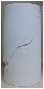 |  |  | 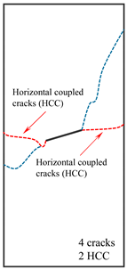 |
| 30° |  | 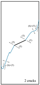 |  | 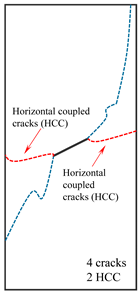 |
| 45° |  |  | 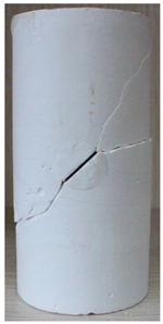 | 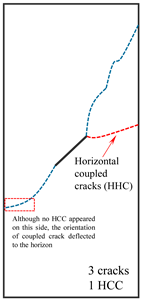 |
| 60° | 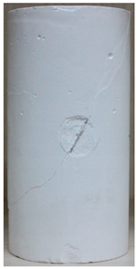 | 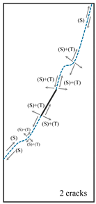 |  |  |
| 75° |  | 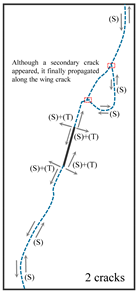 |  |  |
© 2018 by the authors. Licensee MDPI, Basel, Switzerland. This article is an open access article distributed under the terms and conditions of the Creative Commons Attribution (CC BY) license (http://creativecommons.org/licenses/by/4.0/).
Share and Cite
Zhou, Y.; Zhao, C.; Zhao, C.; Ma, C.; Xie, J. Experimental Study on the Fracturing Behaviors and Mechanical Properties of Cracks under Coupled Hydro-Mechanical Effects in Rock-like Specimens. Water 2018, 10, 1355. https://doi.org/10.3390/w10101355
Zhou Y, Zhao C, Zhao C, Ma C, Xie J. Experimental Study on the Fracturing Behaviors and Mechanical Properties of Cracks under Coupled Hydro-Mechanical Effects in Rock-like Specimens. Water. 2018; 10(10):1355. https://doi.org/10.3390/w10101355
Chicago/Turabian StyleZhou, Yimeng, Cheng Zhao, Chunfeng Zhao, Chuangchuang Ma, and Junfei Xie. 2018. "Experimental Study on the Fracturing Behaviors and Mechanical Properties of Cracks under Coupled Hydro-Mechanical Effects in Rock-like Specimens" Water 10, no. 10: 1355. https://doi.org/10.3390/w10101355