Article

Coupled Thermally-Enhanced Bioremediation and Renewable Energy Storage System: Conceptual Framework and Modeling Investigation

1
Department of Environmental Resources Engineering, Humboldt State University, Arcata, CA 95521, USA
2
Department of Civil Engineering, the University of Texas Arlington, Arlington, TX 76019, USA
3
Department of Civil and Environmental Engineering, Colorado School of Mines, Golden, CO 80401, USA
*
Author to whom correspondence should be addressed.
Water 2018, 10(10), 1288; https://doi.org/10.3390/w10101288
Submission received: 7 July 2018 / Revised: 4 September 2018 / Accepted: 16 September 2018 / Published: 20 September 2018
(This article belongs to the Special Issue Groundwater Contamination and Remediation)

Abstract

:
This paper presents a novel method to couple an environmental bioremediation system with a subsurface renewable energy storage system. This method involves treating unsaturated contaminated soil using in-situ thermally enhanced bioremediation; the thermal system is powered by renewable energy. After remediation goals are achieved, the thermal system can then be used to store renewable energy in the form of heat in the subsurface for later use. This method can be used for enhanced treatment of environmental pollutants for which temperature is considered a limiting factor. For instance, this system can be used at a wide variety of petroleum-related sites that are likely contaminated with hydrocarbons such as oil refineries and facilities with above- and underground storage tanks. In this paper, a case-study example was analyzed using a previously developed numerical model of heat transfer in unsaturated soil. Results demonstrate that coupling energy storage and thermally-enhanced bioremediation systems offer an efficient and sustainable way to achieve desired temperature–moisture distribution in soil that will ultimately enhance the microbial activity.

1. Introduction

Soil Borehole Thermal Energy Storage (SBTES) systems are a promising renewable energy storage option. An opportunity to enhance the efficiency of SBTES systems, thus, making them more effective is to link their infrastructure costs with thermal bioremediation. As both SBTES and thermal remediation require the installation of boreholes that can either deliver heat to the subsurface (i.e., thermal remediation) or store heat for later use (i.e., SBTES), linking the two technologies offers a unique opportunity to assist in environmental clean-up and enhance the efficiency of renewable energy storage systems. In this introduction, we will first describe thermal bioremediation, followed by SBTES. How to link the two systems in a practical application is then discussed.

1.1. Bioremediation of Contaminated Soil and Groundwater

One promising technology to clean-up petroleum-contaminated soil and groundwater is bioremediation. Bioremediation uses microbes to degrade, transform, and ultimately remove target pollutants (e.g., petroleum hydrocarbons) from contaminated soil. Bioremediation can be performed in-situ, requiring the targeting of a remediation strategy to the specific subsurface environment, which inherently has site-specific challenges including differences in soil type, moisture, heterogeneities, and resident microorganisms. Despite these difficult to control variables, in-situ bioremediation has many economic and environmental benefits [1].
Environmental conditions affecting bioremediation efficiency include (1) climate (diurnal temperature, precipitation); (2) carbon, nutrient, and oxygen supply; (3) soil conditions (texture, type, moisture, and layering), and (4) contaminant composition and concentration. For example, Mori et al. [2] performed a series of experiments to investigate the effect of soil moisture on the bioremediation efficiency of oil-contaminated soils. They showed that unsaturated conditions prevented bypass flow and allowed dispersion of injected nutrients, resulting in higher bioremediation efficiency than for saturated soil conditions. However, microbes in unsaturated soil systems are more sensitive to the availability of nutrients and changes in temperature than those in comparatively stable saturated soil systems [3,4]. Furthermore, the hydrocarbon concentration trends appear to be season-dependent. For instance, in wet weather, since the water content of soil pore space is higher (i.e., effect of soil moisture), limitation in oxygen diffusion can result in reductions in the activity of aerobic petroleum-degrading microorganism [5]. These findings suggest that bioremediation technology is well suited to the vadose zone but could be enhanced by addressing variables inherent to this region.
Optimum levels of critical environmental factors for in-situ bioremediation can vary with the environmental conditions and contaminated site-characterizations. However, the Environmental Protection Agency (EPA) [6] provides general recommendations for in-situ bioremediation of contaminated unsaturated subsurface soils as listed in Table 1.
Based on the temperature ranges that are optimal for respiration and for growth in the environment, microorganisms that are used for bioremediation of hydrocarbon-contaminated soil can be grouped into two categories; thermophilic and mesophilic. Thermophilic bacteria thrive at relatively high temperatures (~45–75 °C) whereas mesophilic bacteria only survive at moderate temperatures (~15–45 °C). While thermophilic bacteria are also present in colder environments, their population is limited under these conditions [11]. A multitude of bacteria (e.g., B. thermoleovorans, P. aeruginosa, etc.) are capable of biodegrading different categories of petroleum hydrocarbons as detailed in Reference [12] and some listed in Table 2. Many of these species have been isolated from oil-rich environments or geothermally heated regions and have been well studied for petroleum degradation capabilities and characteristics in both laboratory and field settings [13].
It has been shown that temperature plays an important role in controlling the nature and extent of microbial metabolism in the presence of most contaminants, including low-solubility hydrocarbons [17], partly because kinetic processes are temperature driven. Moreover, certain types of bacteria (i.e., thermophilic bacteria) are optimized for elevated temperature conditions.
The temperature dependence of soil microbial activity is usually investigated by measuring soil respiration rate [18]. Several field and laboratory studies have been conducted on measuring the effect of temperature on microbial respiration. Previous studies confirmed the effect of temperature on microbial respiration [18,19,20,21,22]. Lin et al. [19] showed that a temperature rise could increase soil respiration. Their analysis for samples incubated at 35 °C suggested that bacterial structure is related to soil temperate while in samples incubated at 15 °C and 20 °C, it correlates with time. Dijkstra et al. [20] used metabolic tracers and modeling to evaluate the response of soil metabolism to an abrupt change in temperature from 4 to 20 °C. Their results showed that respiration increases almost 10-fold two hours after temperature increases. Abed et al. [21] studied the effect of different temperatures and salinities on respiration activities, oil mineralization and bacterial community composition in desert soils. They monitored CO2 evolution at different temperatures and showed an increase in CO2 evolution and oil mineralization rates with increasing temperature. As mentioned by Boopathy [22], the rate of contaminant conversion during bioremediation depends on the rate of contaminant uptake and metabolism as well as the rate of mass transfer to the cell.
In addition to affecting microorganisms, elevated temperatures also affect the contaminant properties. Elevated temperature results in decreasing contaminant viscosity, increasing its solubility and enhancing diffusivity, all of which are all favorable to increased biodegradation rates. Using a heated and humidified biopile system, Sanscartier et al. [23] showed that raising the temperature of soil by only 5 °C enhanced bioremediation of a soil contaminated by diesel fuel. Using a mathematical model to study dissolution, biodegradation, and diffusion limited desorption of Dense Non-Aqueous Phase Liquid (DNAPL)-contaminated groundwater, Kosegi et al. [24] demonstrated that thermally enhanced bioremediation sites contaminated with DNAPL could reduce effluent concentrations (i.e., the amount of contaminant mass not degraded in-situ) by 94% when temperature increased from 15 °C to 35 °C. They also showed the thermally enhanced bioremediation can reduce clean-up time by 70% compared to ambient conditions. Perfumo et al. [25] experimentally demonstrated increases in temperature in the presence of thermophilic and mesophilic bacteria significantly enhanced the degradation rates of hexadecane-contaminated soil. In unsaturated soil systems, it has been shown that there is a strong correlation between microbial activity and the amount of carbon dioxide released within the soil (i.e., an indicator of microbial respiration) and seasonal fluctuations in air/soil temperature [26,27]. Indeed, microbial activity can be quantified as a function of carbon dioxide flux from soils [28]. According to Hendry et al. [26], the highest soil carbon dioxide concentrations are reported during summer months, indicating the highest biological activity of the year while the minimum concentrations occur in winter months. In terms of depth below the soil surface, carbon dioxide concentrations exhibit a profile of relative decrease with depth in the summer and increase in the winter. This is due to changes to the vertical temperature profile in summer and winter months. Thus, compensating for seasonal and diurnal temperature changes within the unsaturated soil by artificially heating the subsurface has the potential to enhance bioremediation efficiency over time.
Thermally enhanced bioremediation has been previously used in a variety of environmental remediation scenarios. These systems deliver heat to the subsurface using electrical resistance and radio frequency techniques as well as hot fluid injection as reviewed by Hinchee and Smith [29]. Although capable of producing ample heat for remediation enhancement, they demand high amounts of energy, making them very expensive. Perfumo et al. [25] highlighted the importance of further investigation into cost-effective methods to provide thermal energy. One cost-effective method is using renewable energy (e.g., solar, wind) to generate energy requirements for thermally enhanced bioremediation systems as proposed by Nakamura et al. [30] and Rossman et al. [31]. A limitation of renewable energy is its intermittency [31]. An important issue limiting the implementation and use of renewable sources is energy storage as it is not possible to control the timing of the supply of solar or wind energy in spite of their abundance. Therefore, the traditional way of using renewable energy would not provide a continuous heat source to enhance bioremediation. In addition, this would require that systems be linked into electrical grids, thus limiting the deployment of thermally enhanced bioremediation systems to areas with ample power supplies (i.e., not remotely deployable).

1.2. Renewable Energy Storage

Renewable energy resources continue to gain attention as the gap between energy consumption and production grows. Although there are many benefits to renewable energy resources, one unresolved issue is energy storage for use when demand is high. For example, wind or solar energy is produced intermittently and oftentimes at off-peak times of the day. A considerable amount of research has been done on producing renewable energy, yet the storage of renewable energy is oftentimes overlooked. Some research has been undertaken in ways to store renewable energy in the form of electricity; storage of energy as heat can oftentimes be more cost-effective. SBTES is a promising energy storage option in which heat, generated from renewable energy sources, is stored through circulating heated fluid (e.g., water) in geothermal borehole arrays in the subsurface. One of the main concerns hindering the widespread use of SBTES systems is their efficiency. Currently, efficiency ranges between 27–30% over the lifespan of these systems. Recently, McCartney et al. [32] proposed installing SBTES systems in the shallow subsurface above the water table (i.e., unsaturated zone). Installation in the unsaturated zone provides an opportunity to enhance system efficiency by taking advantage of latent and convective heat transfer, resulting in greater heat injection and extraction rates [33,34].

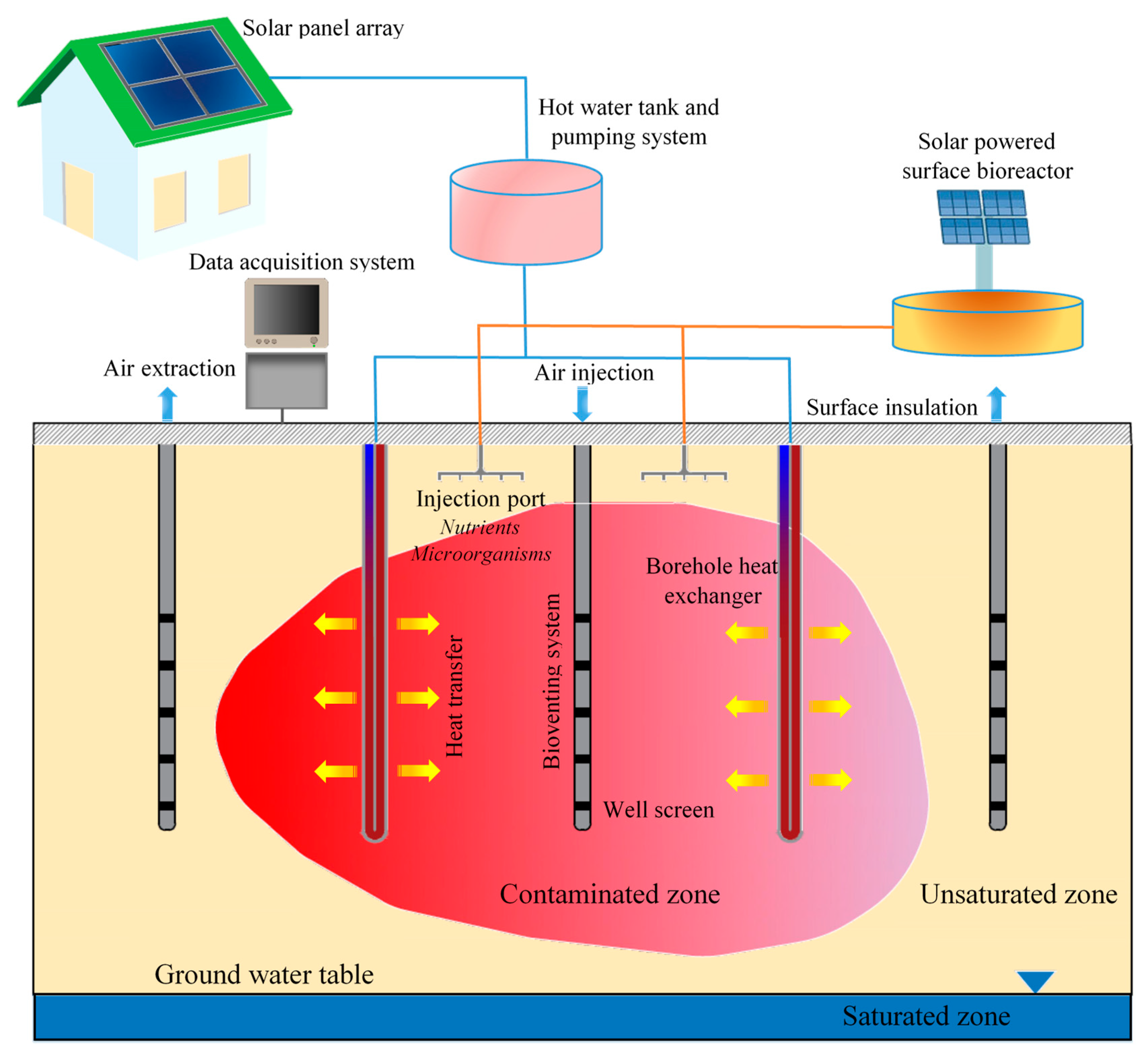
1.3. Coupled Bioremediation and Renewable Energy Storage System

In this paper, we explore the application of a novel approach to treat contaminated soil using an in-situ, thermally enhanced bioremediation system. This approach addresses the intermittency of energy supply to compensate for diurnal and seasonal temperature fluctuations coupled with a long-term energy storage system for subsequent energy requirements after remediation is achieved. The paper specifically focuses on: (a) the improvement of current renewable thermal remediation systems by addressing the intermittency of energy supply (phase I), and (b) the secondary use of a thermal remediation system as a renewable energy storage system (phase II).

2. System Characteristics

The schematics of the proposed enhanced bioremediation/energy storage system can be seen in Figure 1. The system operates in two phases; remediation (phase I) followed by energy storage (phase II). First, heat generated from a renewable energy source (e.g., solar or wind) is stored in the form of hot water or fluid in insulated tanks. The heated fluid is then circulated within the subsurface through a series of closed-loop, u-shaped tubes known as borehole heat exchangers to raise the temperature of the soil. The temperature of the injected fluid can be adjusted based on the application phase. For instance, during the remediation phase with mesophilic bacteria, lower temperatures (i.e., 40–50 °C) in the introduced fluid will be used to achieve temperatures for maximal soil biological activity. During the period of circulation, water within the boreholes returns to the water storage tank to be reheated.
As illustrated in Figure 1, a typical coupled enhanced bioremediation–energy storage system would include several sub-systems. A hot water/fluid storage tank, connected to the renewable energy source and pumping system, will be used to adjust the temperature of heated water or fluid to reach the desired soil temperature range for microbial activity or the heat storage. Solar thermal panels or wind turbines are used to heat up the fluid.
A transition period might be necessary to repress microbial activity in subsurface soil. However, it depends on the state of the microbial activity when the remediation phase is completed. For thermophilic microorganisms, this is achieved by circulating cold fluid through heat exchangers to lower the soil temperature. The decrease in temperature can shift the population of microorganisms and decrease their overall numbers and activity to assure they do not pose any threat to the subsurface environment. In case of mesophilic microorganisms, circulating hot fluid during a transition period can select for microorganisms’ population and growth since these types of microorganisms cannot survive under high temperatures. This provides an analogous pressure that “shocks” the community and represses activity. Organic carbon, nutrient, and oxygen injection should also be ceased during this phase. It is anticipated that the natural population will rebound once temperature, electron donors and acceptors rebound to the prior unperturbed steady state conditions. Subsequently, phase II (soil energy storage) will commence after this transition period. After achieving clean-up goals, the thermal remediation system can serve as a renewable energy storage system (i.e., storage period). During this phase (phase II), hotter fluid (i.e., 80–100 °C) can be circulated within the boreholes. Ultimately, the stored heat can be extracted in the winter by circulating cold water/fluid (i.e., 10 °C).
The solar-powered surface bioreactor is used to provide essential nutrients for microbial growth similar to American Type Culture Collection (ATTC) media described in Reference [35] (US patent 5753122). In most cases, indigenous bacteria are already present in the soil, and this reactor will only be used for biostimulation (adding constituents that enhance microbial growth such as organic carbon and nutrients). The reactor could also be used for bioaugmentation (adding microorganisms) if deemed appropriate. Surface insulation can reduce heat loss through the system by decreasing the soil-atmospheric interaction, especially in cold climates. The insulation layer can include layers of sand, waterproof membrane and insulation materials. The injection ports located below the soil surface are used to deliver a suspension of water, and nutrients to the soil. Percolating downward by gravity, the addition of a suspension enables both biostimulation and bioaugmentation to the system. The type of nutrients and microorganisms should be determined based on contaminant type, properties of the site and other technical considerations.
Moreover, the injection ports can also be used to adjust soil moisture during Phase II and compensate for drying out effect due to heat sources, thus, maximizing the heat transfer rate and system efficiency. As demonstrated in previous studies [33], for each soil type, there might be a critical degree of saturation (i.e., ratio of water content to pore volume) in which overall heat transfer (conduction and convection and latent heat transfer) is maximized. Similarly, as reported by Bear et al. [36], there is also a critical degree of saturation (which depends on the soil type) that causes no considerable drying at hot boundaries.
The bioventing system contains air injection and extraction wells to provide sufficient oxygen for aerobic microorganisms. As depicted in Figure 1, an extraction well is located in the middle of the contaminated zone. The negative pressure that is applied in the extraction well develops in the soil and can enhance remediation through two different mechanisms, volatilization and bioventing. First, the negative pressure gradient can accelerate volatilization of hydrocarbon sorbed to the soil particles. The extraction well collects the volatilized contaminant and provides opportunities for additional treatment before the gas being emitted into the atmosphere. Second, bioventing can help overcome oxygen deficits for aerobic bioremediation through delivering air to the subsurface [37]. More information on the site-specific design of bioventing wells can be found in Reference [38]. In addition, soil samples collected from bioventing wells can provide simpler tools to evaluate the performance and efficiency of the remediation system.
Borehole heat exchangers are u-shape tubes installed in the soil and used to circulate heated water/fluid. After installation, the area around u-tubes is backfilled with grout (e.g., mixture of silica sand and bentonite clay), assuring maximum heat transfer between the heat exchanger and the soil. Spacing and configuration of boreholes are determined based on soil domain properties, soil type, desired temperature, and moisture distribution in the system and the overall efficiency of the bioremediation processes based on the results of mathematical modeling.
The data acquisition system includes data loggers/computer to collect data from the sensor network for real-time analysis of environmental conditions. A series of thermocouples and soil moisture sensors can be strategically installed along with the borehole heat exchangers to simultaneously monitor soil temperature and moisture. Data can be reviewed and used to adjust system inputs (moisture, temperature, flow rate, etc.) to achieve better system efficiency.
Collected data from the sensor network, as well as results of the soil analysis for estimating biodegradation rates can be used to establish appropriate monitoring processes. Long-term monitoring will help to evaluate the performance of bioremediation through which termination time of phase (I) can be determined.
To evaluate remediation efficiency and the transition timing from phase I to phase II (I), the guidelines provided by EPA can be used. Based on these guidelines, soil samples should be collected and analyzed for Total Petroleum Hydrocarbon (TPH) and other contaminants of concerns at least bi-annually basis using standard spectrophotometry methods [39]. Moreover, soil gas samples collected from the bioventing system (extraction wells) should be regularly monitored for O2, CO2, and methane. If volatile organic compounds (VOCs) are present in the contaminated soil, the soil gas can be further analyzed to evaluate the degradation level of such chemicals. The soil gas samples can indicate the rate of microbial activity in the soil. For instance, reduced oxygen levels and higher CO2 concentrations compared to background, support bioremediation activity. Detailed information on long-term performance monitoring can be found in EPA guidelines [40].
This method builds upon pillars of in-situ treatment that minimizes disturbance and economic inputs while using physical, chemical and biological advantages of thermal treatment. It offers some valuable advantages as listed below. It should be mentioned that some of these advantages are also general to any thermally enhanced remediation method but herein with the advantage of the dual purpose of both remediation and energy storage.
  • Elevated temperatures in the soil domain during the bioremediation period (phase I) enhance contaminant attenuation rates: As discussed earlier, temperature can play an important role in increasing the efficacy and rates of bioremediation. In this system, the injected heat can compensate for diurnal and seasonal variations in the soil temperature profile, allowing for more consistent and longer heating periods and thus a shorter remediation time.
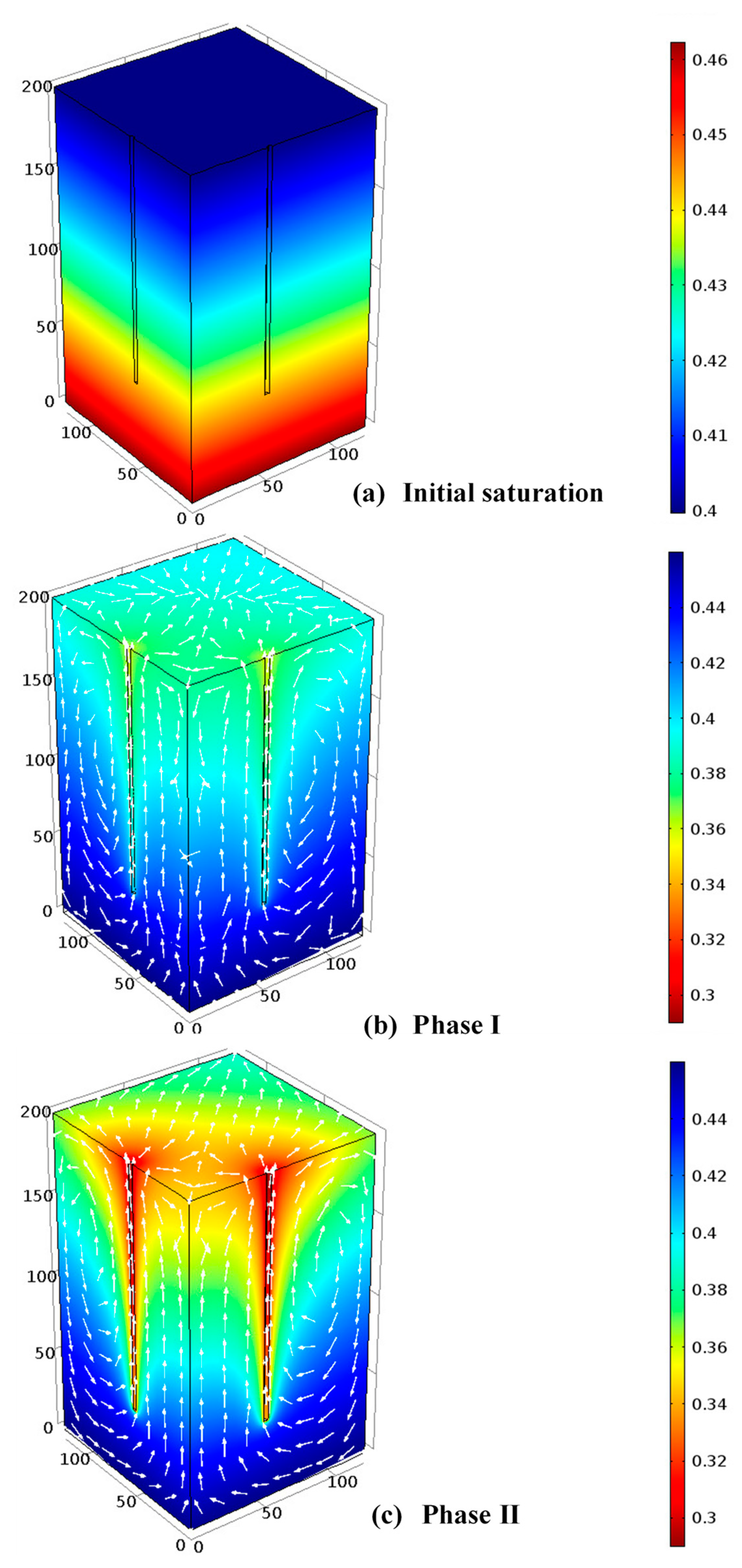
  • Uniform distribution of nutrients/oxygen through moisture redistribution increases biostimulation in unsaturated zone: As discussed in Section 4, moisture movement occurs in the presence of thermal gradients. The moisture circulation in both the liquid and vapor forms/phases can help redistribute oxygen and nutrients that are delivered from injection wells, allowing for the increase in contact between microorganisms and contaminant throughout the domain. This is important as in bioremediation injection wells, the injected nutrients/biomass is consumed very quickly and in the vicinity of wells. Thus, nutrients/biomass is rarely distributed far from the injection wells.
  • Minimal disruption of the site: Installing borehole heat exchangers does not require any excavation and can be done with minimal disturbance of the soil. This is also known to be one of the important advantages of traditional and thermally enhanced bioremediation as well [22].
  • Applicable to both populated and rural areas: Enhanced bioremediation/energy storage systems can be implemented in domestic areas (e.g., under building foundations), and remote/rural locations.
  • Renewable energy consumption: Except for the initial installation costs and routine maintenance, there is minimal energy cost associated with this system, resulting in a considerably cheaper remediation technique than traditional thermal remediation systems.
  • Environmentally friendly: This method links a remediation initiative with a clean and renewable energy storage system. The clean-up has minimal impact to the environment while implementing a sustainable system that allows the long-term use of the renewable energy system. Historically, bioremediation and renewable energy alternatives are well accepted with the public.
  • The proposed method can be implemented in colder environments above freezing point where natural attenuation rates are unacceptably slow. Temperature will enhance the movement of contaminants through the soil which could increase bioavailability.
  • In this method, the elevated soil temperature is considerably lower and easier to control compared to, for instance, electrical resistance or radio frequency methods. Therefore, the potential adverse effect of high temperatures (e.g., mobilizing contaminants, sterilizing microorganism, etc.) is minimal.
  • Long-term energy storage: When the remediation goals are achieved, the system can still be used to store renewable energy without any additional investment or modification.
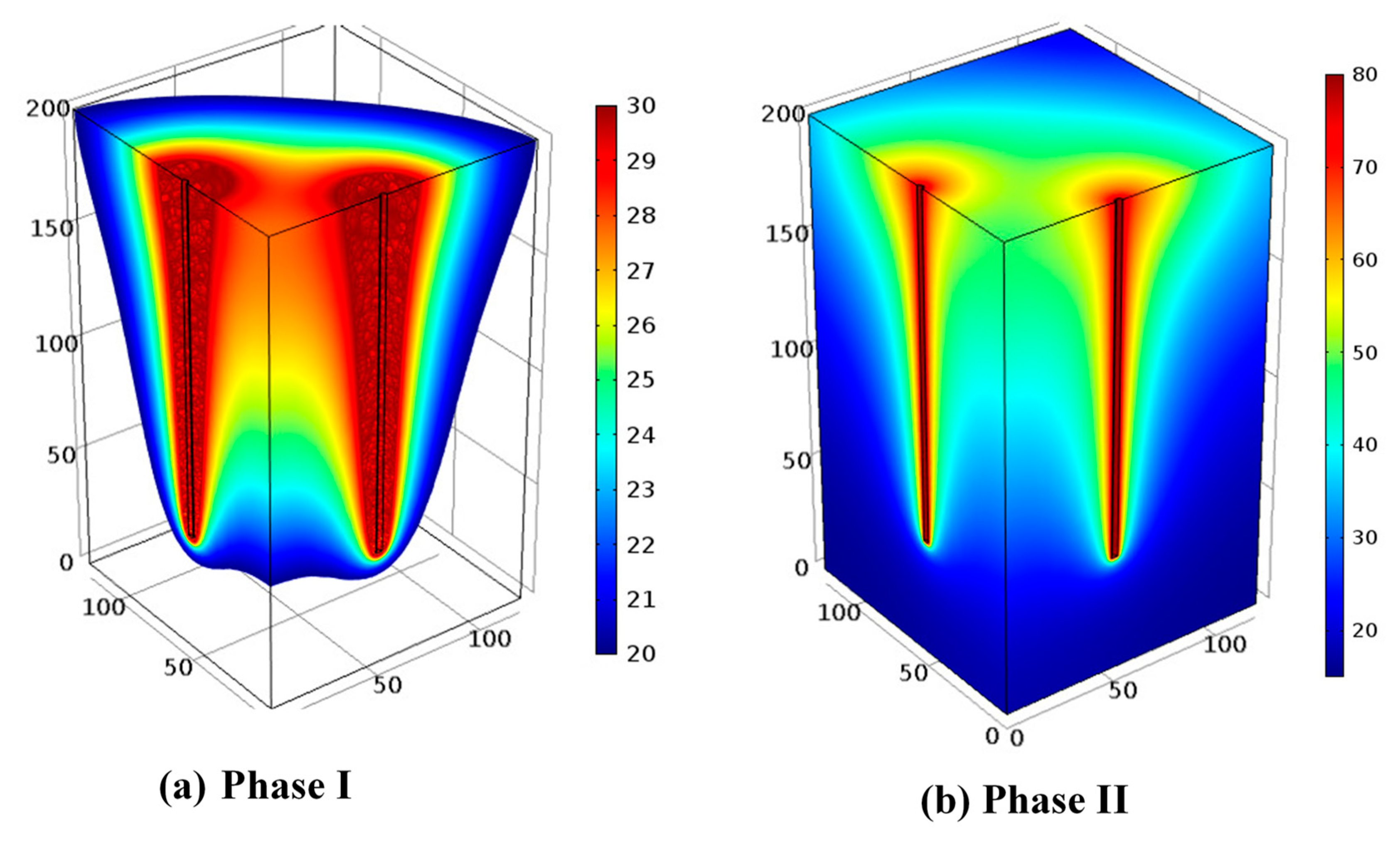
  • Higher energy storage efficiency during phase II: Continuous heating of soil domain during phase (I) without a cooling period in the wintertime will likely increase the efficiency during energy storage phase. Although the transition may involve a cooling phase for the central regions of the contaminated domain (only in case of using thermophilic bacteria), it is expected that the surrounding soil will still have a slightly higher temperature than background temperature. Therefore, it results in a lower temperature gradient between core of the system and the surrounding soil, thus, decreasing the heat loss from the system.
  • The system has limited footprint, and it is not expected to have an extensive environmental impact in upper soil layers.

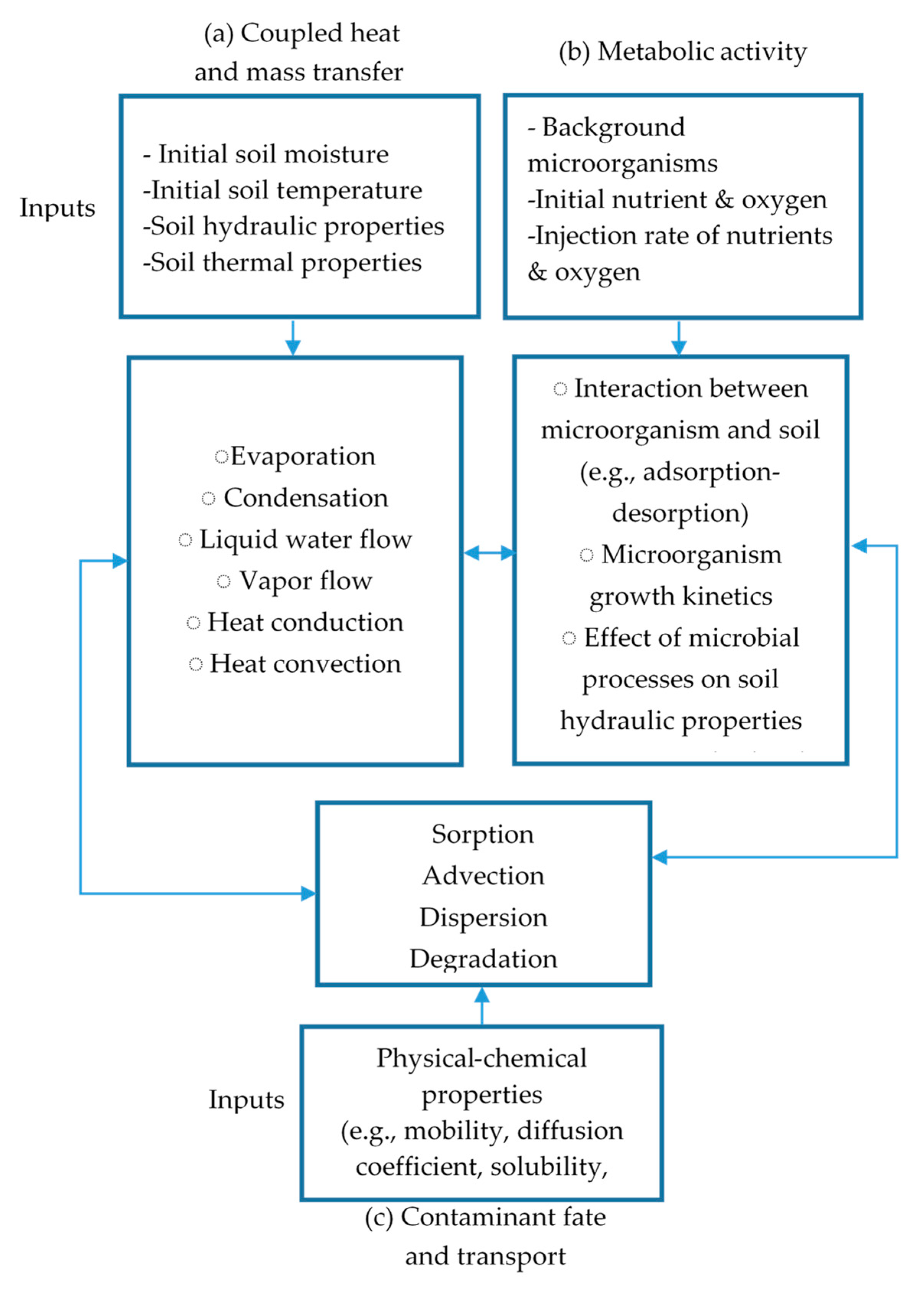
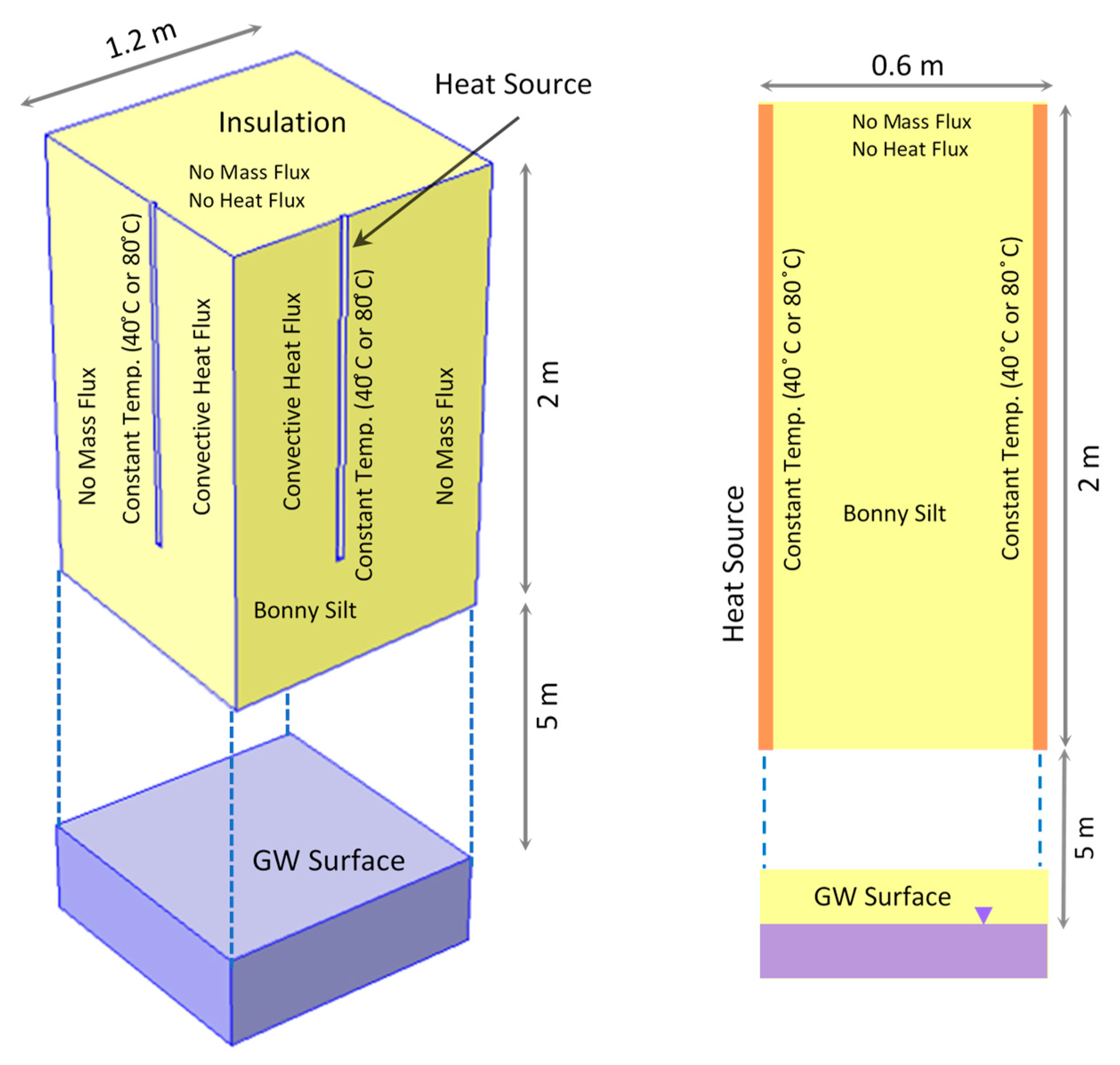
3. Numerical Modeling

In this section, we provide a brief case study, introducing the numerical model used to determine system efficiency. In addition, we provide an example of the application of this model to a hypothetical site.
To develop the mathematical model, three physicochemical/biological areas in the soil should be taken into account: (a) coupled heat and mass transfer, (b) metabolic activity and rates, and (c) contaminant fate and transport. Figure 2 shows a general mathematical modeling framework in designing a coupled thermally enhanced bioremediation–renewable energy storage system and the interrelationships between each component of the framework. It should be mentioned that including or excluding certain processes/assumptions from modeling depends on the problem at hand. The mathematical model is an entirely coupled model in which important parameters are functions of other processes and parameters. For instance, biological activity and growth can alter hydraulic properties of the soil or the temperature can affect both biological processes and multiphase flow in the soil.
As a reminder, the purpose of this paper is to present the concept of coupling enhanced bioremediation and renewable energy storage, it is not to discuss the details of the numerical modeling process. Our intent is not to model the entire system as shown in Figure 1 but rather focus on the enhancement of the system due to temperature effects (i.e., (a) model of Figure 2). In other words, not all of the affecting parameters and their interactions (e.g., effect of biological activity in soil hydraulic properties) are considered in this case study but will rather be presented in future works.

3.1. Simulation of Heat and Mass Transfer

Although much work has been done to numerically study ground heat exchangers [41,42], there is little to no work that investigates the effect of coupled heat and mass (water vapor and liquid water) transfer in presence of heat gradients. Instead, a common assumption in most modeling efforts is to consider soil as a conductive material with constant thermal properties. Although this assumption can be valid in some cases, it will not provide accurate results when modeling heat transfer in the vadose zone. Therefore, in the current study, a non-isothermal numerical model that simulates coupled heat, water vapor, and liquid water flux through the soil and considers non-equilibrium liquid/gas phase change should be used to simulate heat and moisture transfer in the domain. This model has been validated using the data collected from laboratory-scale tank tests that involved heating an unsaturated sand layer. Details of the numerical model development, experimental procedure and results can be found in References [33,34].
Figure 3 shows the domain and boundary conditions used for this case study. As depicted in the figure, no-flux boundary conditions were assumed for both liquid and vapor transfer for all the boundaries. However, constant temperature boundary conditions were applied on the surface of the heat sources whereas the top boundary was assumed to be insulated. For the bottom boundary as well as side boundaries, convective heat flux boundaries were applied. An initial temperature of 15 °C was assumed for the entire domain. Furthermore, the groundwater table was assumed to be 5 m below the bottom of the simulated domain as schematically shown in Figure 3. Natural soil type (Bonny silt) properties were used to perform the simulation. General properties of this soil are available in Appendix A (Table A1 and Figure A1).
The system of differential equations was solved using the COMSOL Multiphysics software package (COMSOL Multiphysics® v. 5.2. www.comsol.com. COMSOL AB, Stockholm, Sweden). The numerical model was developed and validated in previous studies [33,34] and was slightly amended to use here. Two scenarios are modeled: (a) a constant temperature of 40 °C was applied in heat boundaries to achieve desired temperature range (i.e., 20–30 °C) assuming a mesophilic bacteria is used for bioremediation. This scenario helps to illustrate how the system operates during the first phase (remediation process). (b) Assuming the system operates for thermal energy storage purpose, the inlet temperature was increased to 80 °C. Only the first four days of each phase have been simulated.

3.2. Simulation of Bioremediation Process

A significant amount of research has been devoted to developing quantitative relationships between physicochemical and biological processes in polluted soils. A brief review of these relationships can be found in the paper presented by Murphy and Ginn [43]. As they pointed out, there is a linkage between the subsurface transport of bacteria and the biodegradation of dissolved contaminants. Most previous studies are for remediation in saturated soil systems. There are very few focusing on the modeling of the bioremediation process in unsaturated soils. A review of mathematical models to simulate bioremediation in a homogenous soil under unsaturated conditions is available in Reference [44].
As mentioned previously, since direct quantification of microorganism in soil and sediment samples requires invasive sampling and can be biased by system heterogeneity. However, carbon dioxide measurements provide a convenient and rapid analytical tool to estimate bulk microbial heterotrophic activity [45]. A van’t Hoff-Arrhenius-type relationship is usually used to mathematically describe the enhanced microbial activity as a function of temperature [46,47]:
αm = αmo exp [k(T − T0)]
where αm is the microbial carbon dioxide production rate (or microbial activity) at temperature, T, αmo is the microbial carbon dioxide production rate at reference temperature T0 and k is a constant.

4. Results and Discussion

Figure 4 shows the surface plots of the temperature distribution in the soil domain after 4 days of heating using four heat sources for both the remediation and energy storage phases. As seen in Figure 4a, a considerable portion of the domain reaches a temperature ~20–30 °C after 4 days, which is desirable for mesophilic microbial activity. As Figure 4b shows, temperature considerably increases in the center of the domain during the thermal energy storage phase (phase II) because of the injection of a higher temperature fluid (80 °C). The capability to model the heat transfer and storage allows for the design of the most efficient well configuration as well as environmental conditions (e.g., moisture content) to achieve overall system efficiency.
Figure 5 shows the initial (t = 0) and final (t = 4 days) degrees of saturation in both phase I and II. The arrows in Figure 5b,c represent the gas-phase velocity field. A variable initial condition of the degree of saturation in the domain was associated with the gravity drainage of initially saturated soil as seen in Figure 5a. Figure 5b clearly shows how the soil moisture conditions are affected by a temperature rise in the domain (Figure 4). During phase I, the injected fluid temperature is 40 °C. Therefore, in phase I, a limited decrease in moisture is observed as demonstrated in Figure 5b. In addition, the gas-phase velocity field shows the occurrence of convective flow around the heat sources. As mentioned before, moisture redistribution due to convective mass transfer and evaporation/condensation processes in the system can improve the biological processes. In phase II, where the temperature of the injected fluid is higher (80 °C), extended drying occurred in the domain (Figure 5c). This is not a concern from a remediation standpoint (remediation has already finished when phase II begins) but can affect system efficiency. However, using the real-time monitoring data, moisture injection ports installed in the surface of the system can be used to compensate for the moisture decrease in the domain.
To demonstrate the effect of temperature on microbial activity for phase I of the example case, we calculated the ratio of carbon dioxide production compared to a reference value of carbon production at the initial conditions. Constant values for Equation (1) were selected from [44] (k = 0.10555 and αmo = 1.5925 × 10⁻¹⁷). Figure 6 shows the αmmo ratio at a single point located in the middle of the domain. As shown in Figure 6, the microbial activity increases more than twice its reference value due to a temperature rise of 10 °C in the domain. The temperature gradient reaches steady state condition in a short amount of time (i.e., few days) that could boost microbial activity until the transition period. During the transition period, when the temperature will increase above a critical value (i.e., 40 °C for mesophiles) that leads to a regime shift of the microorganism. The timing in ecological shift across the temperature domain during phase I and the transition period could be considered as a design constraint.

5. Conclusions

This paper presents the conceptual model of a coupled renewable energy storage and thermally-enhanced bioremediation system. The results of this study suggest that such a coupled system offers more efficient and sustainable way to achieve desired temperature–moisture distribution in soil that can be used to optimize desired microbial activity. The numerical simulation of a simple case study showed that by adjusting the inlet temperature, desired temperature distribution for both enhanced bioremediation and heat storage could be achieved. The proposed method of coupling these two concepts allows for a more cost-effective and sustainable alternative than implementing the systems individually. It is noted that for more accurate and efficient design, realistic domain size, number, and configuration of heat exchangers, boundary and initial conditions should be used in field applications.

6. Patents

A provisional patent application directed to a coupled thermally enhanced bioremediation and energy storage system and has been filed with the US Patent and Trademark Office and assigned Application No. 62/353475.

Author Contributions

Conceptualization, A.M.; Methodology, A.M.; Software, A.M.; Validation, A.M.; Formal analysis, A.M.; Investigation, A.M.; Resources, A.M. and K.M.S.; Data Curation, A.M.; Writing-Original Draft preparation, A.M.; Writing-Review and editing, A.M., K.M.S. and J.O.S.; Visualization, A.M.; Supervision, K.M.S. and J.O.S.; Project administration, K.M.S.; Funding acquisition, K.M.S.

Funding

This research was funded in part by the National Science Foundation (NSF) Sustainable Energy Pathways (SEP) Collaborative Project Award No. CMMI-1230544 and Award No. 1447533. Any opinion, findings, and conclusions or recommendations expressed herein are those of the authors and do not necessarily reflect the views of those providing technical input or financial support.

Conflicts of Interest

The authors declare no conflict of interest. The trade names mentioned herein are merely for identification purposes and do not constitute endorsement by a party involved in this study.

Appendix A

This appendix contains information on hydraulic and thermal properties of soil that was used to perform numerical simulation.
Table A1. Selected hydraulic properties of soil used to perform numerical simulations.
d50 (mm)PorosityResidual Volumetric Water Content (m/m)Saturated Hydraulic Conductivity, Ks, (m·s−1)van Genuchten Parameters
Alpha (kPa−1)n
0.0390.4300.0301.3 × 10−60.08631.58
Figure A1. Thermal conductivity-Saturation curve for Bonny Silt.
Water 10 01288 g0a1

References

  1. Balba, M.T.; Al-Awadhi, N.; Al-Daher, R. Bioremediation of oil-contaminated soil: Microbiological methods for feasibility assessment and field evaluation. J. Microbiol. Methods 1998, 32, 155–164. [Google Scholar] [CrossRef]
  2. Mori, Y.; Suetsugu, A.; Matsumoto, Y.; Fujihara, A.; Suyama, K. Enhancing bioremediation of oil-contaminated soils by controlling nutrient dispersion using dual characteristics of soil pore structure. Ecol. Eng. 2013, 51, 237–243. [Google Scholar] [CrossRef]
  3. Fierer, N.; Allen, A.S.; Schimel, J.P.; Holden, P.A. Controls on microbial CO2 production: A comparison of surface and subsurface soil horizons. Glob. Chang. Biol. 2003, 9, 1322–1332. [Google Scholar] [CrossRef]
  4. Fierer, N.; Jackson, R.B. The diversity and biogeography f soil bacterial communities. Proc. Natl. Acad. Sci. USA 2006, 103, 626–631. [Google Scholar] [CrossRef] [PubMed]
  5. Franzmann, P.D.; Robertson, W.J.; Zappia, L.R.; Davis, G.B. The role of microbial populations in the containment of aromatichydrocarbons in the subsurface. Biodegradation 2002, 13, 65–78. [Google Scholar] [CrossRef] [PubMed]
  6. Sims, J.L.; Sims, R.C.; DuPont, R.R.; Matthews, E.; Russell, H.H. In-Situ Bioremediation of Contaminated Unsaturated Subsurface Soils; Ann Arbor Press: Ann Arbor, MI, USA, 1993. [Google Scholar]
  7. Sims, R.C.; Sorensen, D.L.; Sims, J.; McLean, J.E.; Mahmood, R.; Dupont, R.R. Review of In-Place Treatment Techniques for Contaminated Surface Soils—Volume 2: Background Information for In-Situ Treatment; Utah State University: Logan, UT, USA, 1984. [Google Scholar]
  8. Huddleston, R.L.; Bleckmann, C.A.; Wolfe, J.R. Land treatment—Biological degradation processes. In Land Treatment: A Hazardous Waste Management Alternative; Loehr, R.C., Malina, J.F., Jr., Eds.; Center for Research in Water Recourses, University of Texas: Austin, TX, USA, 1986; pp. 41–62. [Google Scholar]
  9. Rochkind, M.L.; Blackburn, J.W.; Sayler, G.S. Microbial Decomposition of Chlorinated Aromatic Compounds; National Technical Information Service: Springfield, VA, USA, 1986; pp. 2–86.
  10. Paul, E.A.; Clark, F.E. Soil Microbiology and Biochemistry; Academic Press, Inc.: San Diego, CA, USA, 1998. [Google Scholar]
  11. Corwin, P. What are high-temperature bacteria doing in cold environments? Trends Microbiol. 2002, 10, 120–121. [Google Scholar]
  12. Perfumo, A.; Banat, I.M.; Marchant, R. The use of thermophilic bacteria in accelerated hydrocarbon bioremediation. In Environmental Problems in Coastal Regions VI: Including Oil Spill Studies; Brebbia, C.A., Ed.; WIT Press: Southampton, UK, 2006; pp. 67–77. [Google Scholar]
  13. Marchant, R.; Sharkey, F.H.; Banat, I.M.; Rahman, T.J.; Perfumo, A. The degradation of n-hexadecane in soil by thermophilic geobacilli. FEMS Microbiol. Ecol. 2006, 56, 44–54. [Google Scholar] [CrossRef] [PubMed] [Green Version]
  14. Lugowsky, A.J.; Palamteer, G.A.; Boose, T.R.; Merriman, J.E. Biodegradation Process for Detoxifying Liquid Streams. U.S. Patent 5,656,169, 12 August 1997. [Google Scholar]
  15. Markl, H.; Antranikian, G.; Becker, P.; Markossian, S. Aerobic Biodegradation of Aromatic Compounds Having Low Water Solubility Using Bacillus Thermoleovorans Strain DSM 10561. U.S. Patent 5,965,431, 12 October 1999. [Google Scholar]
  16. Feitkenhauer, H.; Müller, R.; MAuml, H. Degradation of polycyclic aromatic hydrocarbons and long chain alkanes at 6070 C by Thermus and Bacillus spp. Biodegradation 2003, 14, 367–372. [Google Scholar] [CrossRef] [PubMed]
  17. Margesin, R.; Schinner, F. Biodegradation and bioremediation of hydrocarbons in extreme environments. Appl. Microbiol. Biotechnol. 2001, 56, 650–663. [Google Scholar] [CrossRef] [PubMed]
  18. Pietikäinen, J.; Pettersson, M.; Bååth, E. Comparison of temperature effects on soil respiration and bacterial and fungal growth rates. FEMS Microbiol. Ecol. 2005, 52, 49–58. [Google Scholar] [CrossRef] [PubMed] [Green Version]
  19. Lin, Y.T.; Jia, Z.; Wang, D.; Chiu, C.Y. Effects of temperature on the composition and diversity of bacterial communities in bamboo soils at different elevations. Biogeosciences 2017, 14, 4879–4889. [Google Scholar] [CrossRef] [Green Version]
  20. Dijkstra, P.; Thomas, S.C.; Heinrich, P.L.; Koch, G.W.; Schwartz, E.; Hungate, B.A. Effect of temperature on metabolic activity of intact microbial communities: Evidence for altered metabolic pathway activity but not for increased maintenance respiration and reduced carbon use efficiency. Soil Biol. Biochem. 2011, 43, 2023–2031. [Google Scholar] [CrossRef]
  21. Abed, R.M.; Al-Kharusi, S.; Al-Hinai, M. Effect of biostimulation, temperature and salinity on respiration activities and bacterial community composition in an oil polluted desert soil. Int. Biodeterior. Biodegrad. 2015, 98, 43–52. [Google Scholar] [CrossRef]
  22. Boopathy, R. Factors limiting bioremediation technologies. Bioresour. Technol. 2000, 74, 63–67. [Google Scholar] [CrossRef]
  23. Sanscartier, D.; Zeeb, B.; Koch, I.; Reimer, K. Bioremediation of diesel-contaminated soil by heated and humidified biopile system in cold climates. Cold Reg. Sci. Technol. 2009, 55, 167–173. [Google Scholar] [CrossRef]
  24. Kosegi, J.M.; Minsker, B.S.; Dougherty, D.E. Feasibility study of thermal in-situ bioremediation. J. Environ. Eng. 2000, 126, 601–610. [Google Scholar] [CrossRef]
  25. Perfumo, A.; Banat, I.M.; Marchant, R.; Vezzulli, L. Thermally enhanced approaches for bioremediation of hydrocarbon-contaminated soils. Chemosphere 2007, 66, 179–184. [Google Scholar] [CrossRef] [PubMed]
  26. Hendry, M.J.; Mendoza, C.A.; Kirkland, R.A.; Lawrence, J.R. Quantification of transient CO2 production in a sandy unsaturated zone. Water Resour. Res. 1999, 35, 2189–2198. [Google Scholar] [CrossRef]
  27. Hiraishi, A.; Yamanaka, Y.; Narihiro, T. Seasonal microbial community dynamics in a flowerpot-using personal composting system for disposal of household biowaste. J. Gen. Appl. Microbiol. 2000, 46, 133–146. [Google Scholar] [CrossRef] [PubMed]
  28. Brouillard, B.M.; Mikkelson, K.M.; Bokman, C.M.; Berryman, E.M.; Sharp, J.O. Extent of localized tree mortality influences soil biogeochemical response in a beetle-infested coniferous forest. Soil Biol. Biochem. 2017, 114, 309–318. [Google Scholar] [CrossRef]
  29. Hinchee, R.E.; Smith, L.A. In-Situ Thermal Technologies for Site Remediation; CRC Press: Boca Raton, FL, USA, 1992. [Google Scholar]
  30. Nakamura, T.; Senior, C.L.; Burns, E.G.; Bell, M.D. Solar-powered soil vapor extraction for removal of dense non-aqueous phase organics from soil. J. Environ. Sci. Health Part A 2000, 35, 795–816. [Google Scholar] [CrossRef]
  31. Rossman, A.J.; Hayden, N.J.; Rizzo, D.M. Low-temperature soil heating using renewable energy. J. Environ. Eng. 2006, 132, 537–544. [Google Scholar] [CrossRef]
  32. McCartney, J.S.; Ge, S.; Reed, A.; Lu, N.; Smits, K. Soil-borehole thermal energy storage systems for district heating. In Proceedings of the European Geothermal Congress, Pisa, Italy, 3–7 June 2013; pp. 1–10. [Google Scholar]
  33. Moradi, A.; Smits, K.M.; Cihan, A.; Massey, J.; McCartney, J.M. Impact of coupled heat transfer and water flow on soil borehole thermal energy storage (SBTES) systems: Experimental and modeling investigation. Geothermics 2015, 57, 56–72. [Google Scholar] [CrossRef] [Green Version]
  34. Moradi, A.; Smits, K.M.; Lu, N.; McCartney, J.S. Heat transfer in unsaturated soil with application to borehole thermal energy storage. Vadose Zone J. 2016, 15. [Google Scholar] [CrossRef]
  35. Taylor, R.T.; Jackson, K.J.; Duba, A.G.; Chen, C.I. In Situ Thermally Enhanced Biodegradation of Petroleum Fuel Hydrocarbons and Halogenated Organic Solvents. U.S. Patent 5,753,122, 19 May 1998. [Google Scholar]
  36. Bear, J.; Bensabat, J.; Nir, A. Heat and mass transfer in unsaturated porous media at a hot boundary: I. One-dimensional analytical model. Transp. Porous Med. 1991, 6, 281–298. [Google Scholar] [CrossRef]
  37. Hoeppel, R.E.; Hinchee, R.E.; Arthur, M.F. Bioventing soils contaminated with petroleum hydrocarbons. J. Ind. Microbiol. 1991, 8, 141–146. [Google Scholar] [CrossRef]
  38. Hinchee, R.E. Bioventing of Petroleum Hydrocarbons. In Handbook of Bioremediations; CRC Press: Boca Raton, FL, USA, 1993. [Google Scholar]
  39. United States Environmental Protection Agency (USEPA). Test Method for Evaluating Total Recoverable Petroleum Hydrocarbon, Method 418.1 (Spectrophotometric, Infrared); Government Printing Office: Washington, DC, USA, 1978.
  40. United States Environmental Protection Agency (USEPA). How to Evaluate Alternative Cleanup Technologies for Underground Storage Tank Sites. A guide for Corrective Action Reviewers; EPA 510-R-04-002; Office of Solid Waste and Emergency Response: Washington, DC, USA, 2004.
  41. Rees, S.J.; He, M. A three-dimensional numerical model of borehole heat exchanger heat transfer and fluid flow. Geothermics 2013, 46, 1–13. [Google Scholar] [CrossRef] [Green Version]
  42. Zeng, H.; Diao, N.; Fang, Z. Efficiency of vertical geothermal heat exchangers in the ground source heat pump system. J. Ther. Sci. 2003, 12, 77–81. [Google Scholar] [CrossRef]
  43. Murphy, E.M.; Ginn, T.R. Modeling microbial processes in porous media. Hydrogeol. J. 2000, 8, 142–158. [Google Scholar] [CrossRef]
  44. Borsi, I.; Fasano, A. A general model for bioremediation processes of contaminated soils. Int. J. Adv. Eng. Sci. Appl. Math. 2009, 1, 33–42. [Google Scholar] [CrossRef]
  45. Chapatwala, K.D.; Babu, G.R.V.; Vijaya, O.K.; Armstead, E.; Palumbo, A.V.; Zhang, C.; Phelps, T.J. Effect of temperature and yeast extract on microbial respiration of sediments from a shallow coastal subsurface and vadose zone. Appl. Biochem. Biotechnol. 1996, 57, 827–835. [Google Scholar] [CrossRef] [PubMed]
  46. Wood, B.D.; Keller, C.K.; Johnstone, D.L. In-situ measurement of microbial activity and controls on microbial CO2 production in the unsaturated zone. Water Resour. Res. 1993, 29, 647–659. [Google Scholar] [CrossRef]
  47. Or, D.; Smets, B.F.; Wraith, J.M.; Dechesne, A.; Friedman, S.P. Physical constraints affecting bacterial habitats and activity in unsaturated porous media—A review. Adv. Water Resour. 2007, 30, 1505–1527. [Google Scholar] [CrossRef]
Figure 1. Schematic of the proposed coupled enhanced bioremediation–energy storage system.
Water 10 01288 g001
Figure 2. Mathematical modeling framework for a fully coupled thermally enhanced bioremediation–energy storage system.
Water 10 01288 g002
Figure 3. Three- and two-dimensional schematics of the simulated domain as well as boundary conditions used in the simulation. Due to symmetry, only a quarter of the domain is modeled. The line heat sources have a constant temperature (40 °C or 80 °C). The side boundaries are modeled as convective heat transfer boundaries. It is assumed that the surface of the domain is insulated (GW: Ground Water).
Water 10 01288 g003
Figure 4. Temperature (°C) distribution in the domain after 4 days for (a) remediation phase and (b) storage phase. For the remediation phase, the part of the domain that has a temperature between 20–30 °C is shown. Only a quarter of the domain is presented.
Water 10 01288 g004
Figure 5. Saturation distribution: (a) before applying heat (t = 0 days); (b) after applying heat in phase I (t = 4 days) and (c) after applying heat in phase (II) (t = 4 days). Arrows in figure (b,c) show the gas phase velocity field.
Water 10 01288 g005
Figure 6. Ratio of carbon dioxide production after applying heat with respect to the reference value of carbon production at initial temperature (αmmo) at a single point located in the middle of the domain.
Water 10 01288 g006
Table 1. Optimum levels of some important environmental factors for in-situ bioremediation of contaminated unsaturated subsurface soils (table amended from [6]).
Environmental FactorOptimum Range *
Soil moisture25–85% of soil porosity
OxygenAerobes > 0.2 mg/L and Anaerobes thrive in the absence of oxygen
Redox potentialAerobes > 50 mV and Anaerobes < 50 mV
pH5.5–8.5
NutrientsSufficient for microbial growth
* As stated in the Environmental Protection Agency (EPA) report [6], these ranges are obtained from References [7,8,9,10].
Table 2. Potential microorganism for hydrocarbon biodegradation.
Microorganism NameIdeal Temperature
Consortium mainly of Pseudomonas sp. [14]40–42 °C
P. aeruginosa AP02-1 [12]45 °C
B. thermoleovorans DSM 10561 [15]45–60 °C
G. thermoleovorans T80 [13]60 °C
Thermus & Bacillus sp. [16]60–70 °C

