
Study of the Tensile Properties of CFRP Strengthened Steel Plates

Abstract
:
1. Introduction
2. Experimental Section
2.1. General

| Series | Specimen | Temperature (°C) | Sequence | Number of CFRP layers |
|---|---|---|---|---|
| L | C/S | 25 | C+S | 1 |
| 2C/S | 25 | C+C+S | 2 | |
| 3C/S | 25 | C+C+C+S | 3 | |
| 4C/S | 25 | C+C+C+C+S | 4 | |
| S | 4C/S | 25 | C+C+C+C+S | 4 |
| 3C/S/C | 25 | C+S+C+C+C | 4 | |
| 2C/S/2C | 25 | C+C+S+C+C | 4 | |
| T | C/S | 25 | C+S | 1 |
| C/S-T30 | 30 | C+S | 1 | |
| C/S-T35 | 35 | C+S | 1 | |
| C/S-T40 | 40 | C+S | 1 | |
| C/S-T45 | 45 | C+S | 1 | |
| C/S-T50 | 50 | C+S | 1 | |
| C/S-T55 | 55 | C+S | 1 | |
| C/S-T60 | 60 | C+S | 1 | |
| C/S-T70 | 70 | C+S | 1 | |
| C/S-T80 | 80 | C+S | 1 | |
| C/S-T100 | 100 | C+S | 1 | |
| C/S-T120 | 120 | C+S | 1 |
2.2. Materials
| Material | Thickness (mm) | Young’s modulus (GPa) | Yield strength (MPa) | Ultimate strength (MPa) | Failure strain (%) |
|---|---|---|---|---|---|
| Steel plate | 2 | 185 | 271 | 364 | 28 |
| CFRP sheet | 0.111 | 252 | – | 3,553 | 1.4 |
| Epoxy resin | – | ≥2.5 | – | ≥30.0 | – |
2.3. Specimens
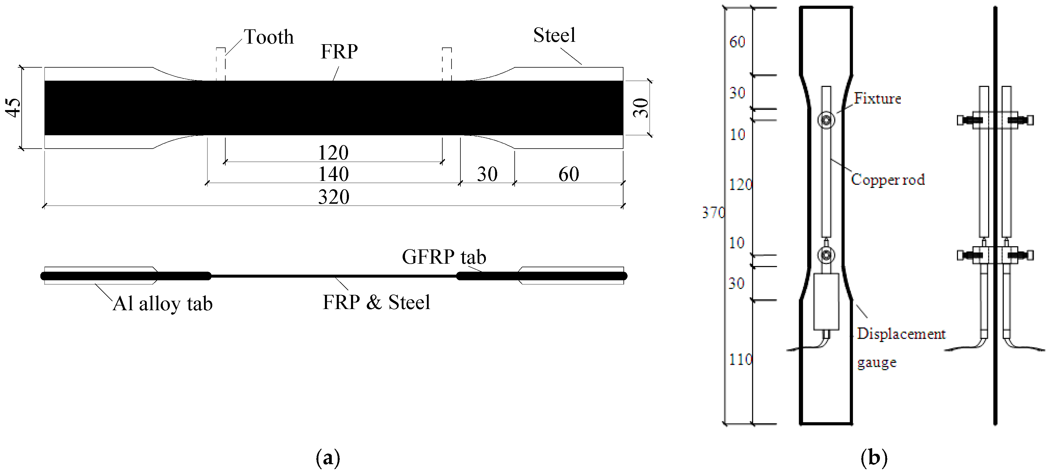
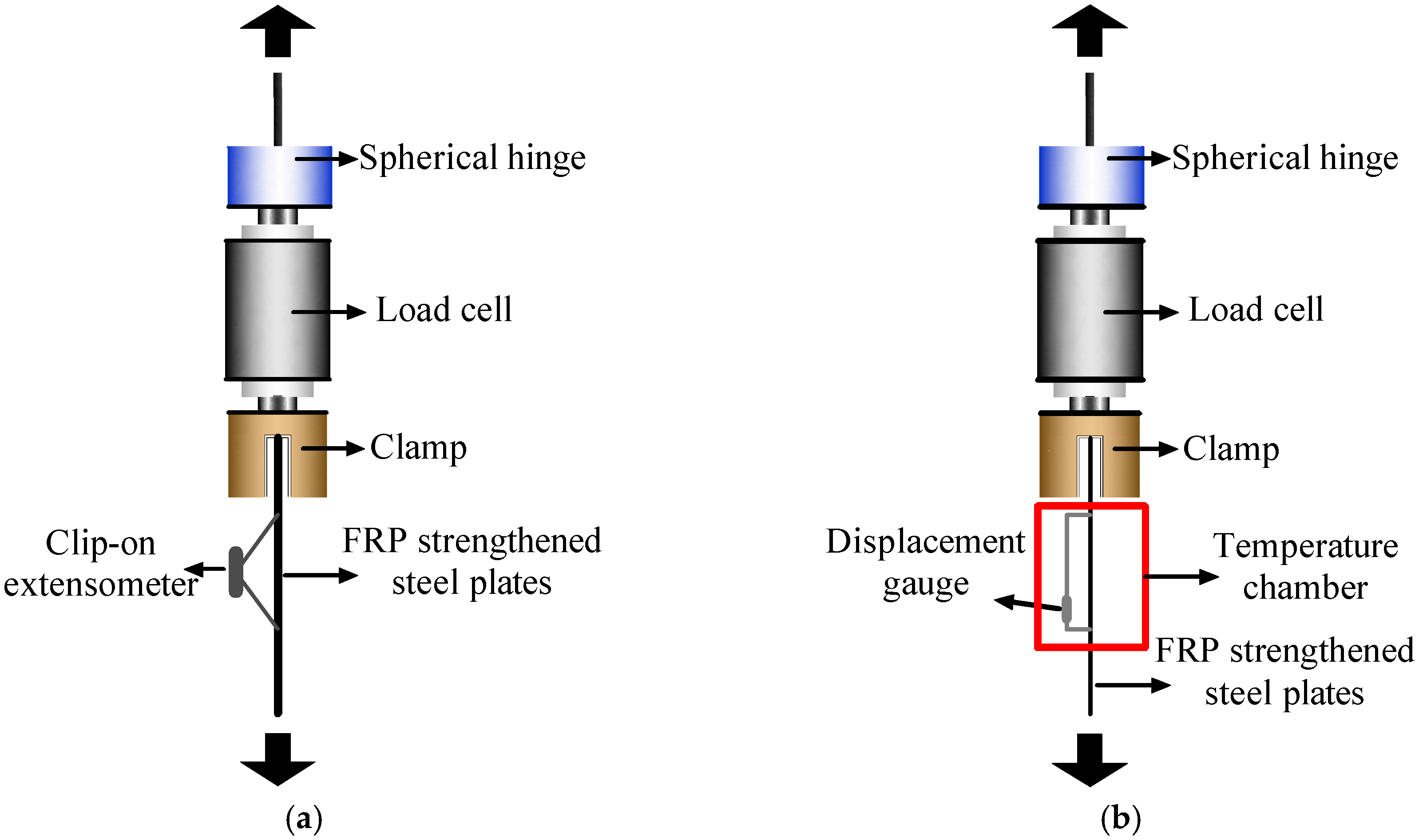
2.4. Test Setup and Instrumentation
3. Results and Discussion
| Series | Specimen | KI | Py | KII | Pu | Failure mode | ||||||||
|---|---|---|---|---|---|---|---|---|---|---|---|---|---|---|
| Exp. (kN/mm) | CV (%) | Theo. (kN/mm) | Exp. (kN) | CV (%) | Theo. (kN) | Exp. (kN/mm) | CV (%) | Theo. (kN/mm) | Exp. (kN) | CV (%) | Theo. (kN) | |||
| L | S | - | - | 92.5 | - | - | 16.3 | - | - | 0 | - | - | 16.3 | - |
| C/S | 95.9 | 9.1 | 99.5 | 17.3 | 5.3 | 17.5 | 7.0 | 11.4 | 7.0 | 28.6 | 6.7 | 28.1 | LF+D | |
| 2C/S | 106.0 | 7.8 | 106.5 | 18.6 | 11.2 | 18.7 | 12.1 | 12.3 | 14.0 | 39.7 | 11.1 | 39.9 | LF+D | |
| 3C/S | 103.9 | 9.4 | 113.5 | 19.4 | 8.7 | 19.9 | 17.2 | 8.8 | 21.0 | 48.1 | 10.3 | 51.8 | LF+D | |
| 4C/S | 94.9 | 7.2 | 120.5 | 20.2 | 4.9 | 21.2 | 20.7 | 12.1 | 28.0 | 56.0 | 12.9 | 63.6 | LF+D | |
| S | 4C/S | 94.9 | 7.2 | 120.5 | 20.2 | 4.9 | 21.2 | 24.3 | 12.1 | 28.0 | 56.0 | 12.9 | 63.6 | LF+D |
| 3C/S/C | 118.7 | 9.8 | 120.5 | 20.4 | 5.7 | 21.2 | 28.9 | 10.4 | 28.0 | 59.7 | 9.1 | 63.6 | LF+D | |
| 2C/S/2C | 120.3 | 5.6 | 120.5 | 20.6 | 8.8 | 21.2 | 33.0 | 15.7 | 28.0 | 63.2 | 4.5 | 63.6 | LF+S+D | |
| T | C/S | 95.9 | 9.1 | - | 17.3 | 5.3 | - | 7.0 | 11.4 | 7.0 | 28.6 | 6. 7 | 27.6 | LF+D |
| C/S-T30 | 93.4 | 8.8 | - | 17.3 | 6.1 | - | 6.8 | 12.8 | 6.9 | 27.4 | 10.2 | 27.0 | LF+S+D | |
| C/S-T35 | 93.3 | 7.3 | - | 17.2 | 10.0 | - | 7.1 | 11.9 | 6.7 | 25.5 | 9.0 | 26.1 | LF+S+D | |
| C/S-T40 | 92.7 | 9.9 | - | 17.0 | 4.3 | - | 5.6 | 15.6 | 6.1 | 24.1 | 13.3 | 24.7 | LF+S+D | |
| C/S-T45 | 93.1 | 5.6 | - | 16.9 | 11.9 | - | 5.4 | 13.2 | 5.1 | 23.9 | 7.6 | 23.3 | IF | |
| C/S-T50 | 92.8 | 8.3 | - | 16.8 | 6.7 | - | 4.1 | 9.9 | 4.1 | 22.1 | 8.9 | 22.1 | IF+S | |
| C/S-T55 | 90.4 | 7.5 | - | 16.2 | 5.9 | - | 3.3 | 10.4 | 3.5 | 21.5 | 2.0 | 21.3 | IF | |
| C/S-T60 | 91.0 | 5.8 | - | 16.1 | 8.2 | - | 3.1 | 5.8 | 3.3 | 20.5 | 3.8 | 20.9 | IF | |
| C/S-T70 | 89.5 | 5.9 | - | 16.3 | 11.3 | - | 3.2 | 3.4 | 3.2 | 21.2 | 4.1 | 20.5 | IF | |
| C/S-T80 | 90.5 | 4.7 | - | 16.0 | 5.8 | - | 3.4 | 4.1 | 3.2 | 20.7 | 3.9 | 20.5 | IF | |
| C/S-T100 | 89.3 | 3.5 | - | 16.0 | 7.6 | - | 3.0 | 1.7 | 3.2 | 19.7 | 2.1 | 20.5 | IF | |
| C/S-T120 | 90.2 | 3.8 | - | 16.1 | 1.9 | - | 3.3 | 3.0 | 3.2 | 20.4 | 5.6 | 20.5 | FF | |
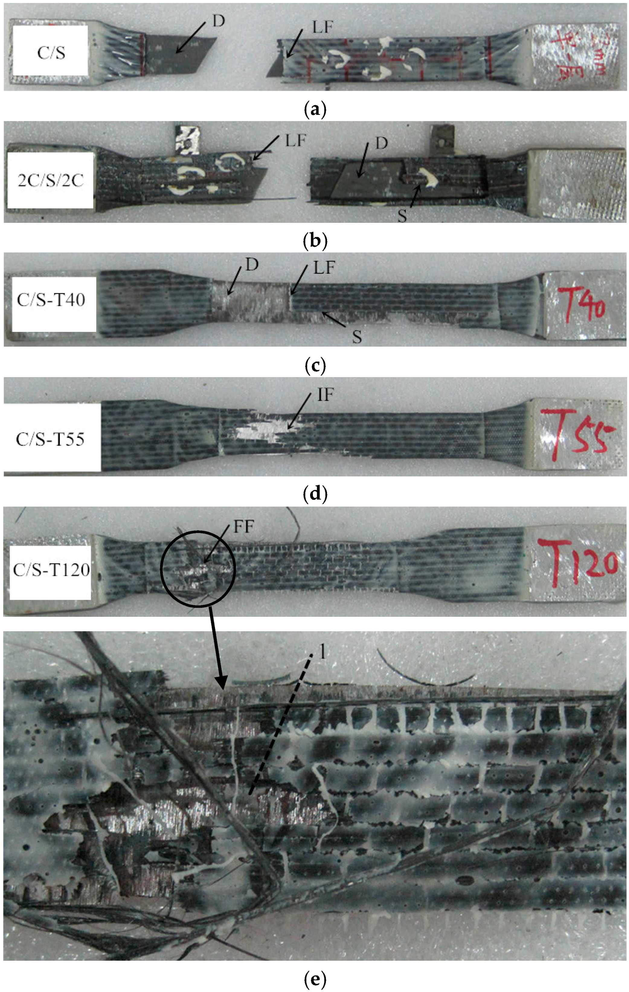
3.1. Failure Modes
3.2. Strengthening and Stiffening Effects


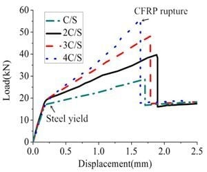
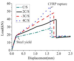
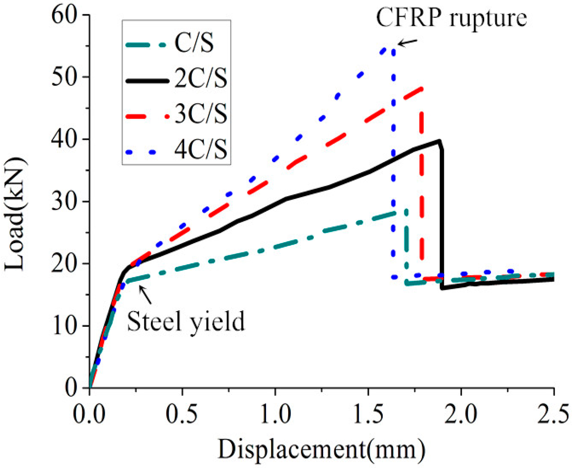
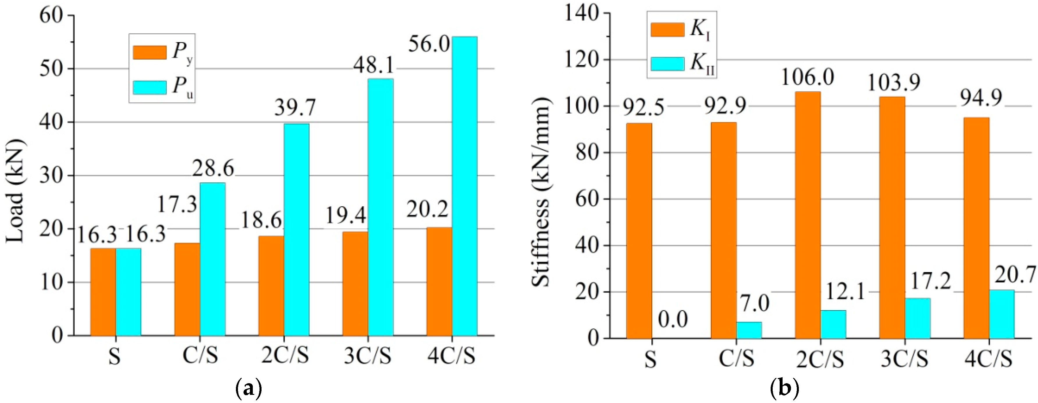
3.2.1. Effects of the Number of CFRP Layers

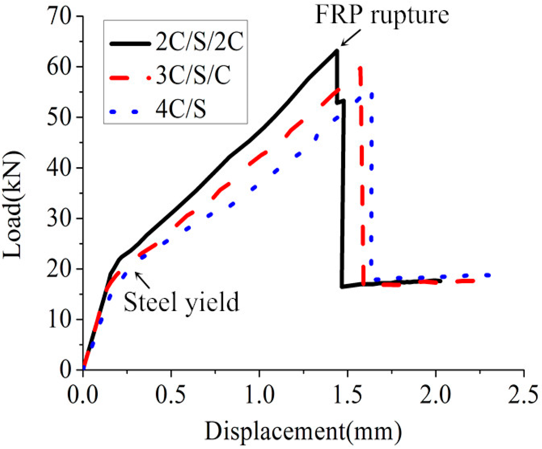
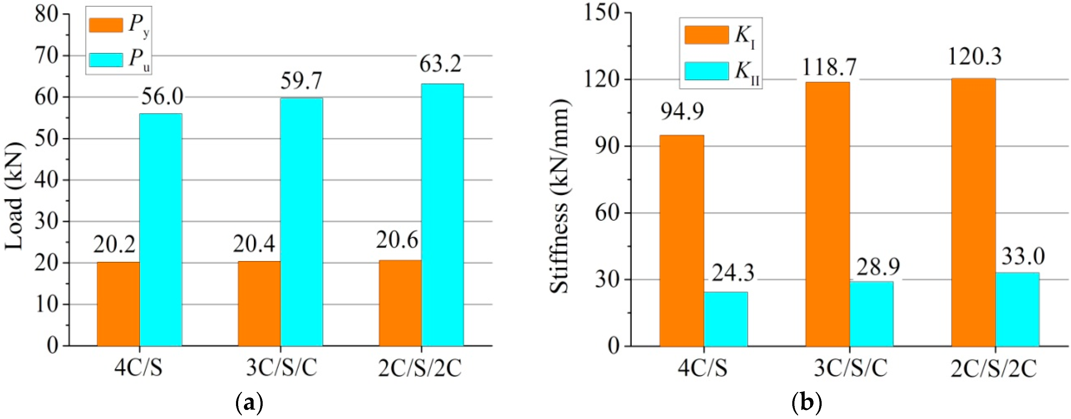
3.2.2. Effects of Strengthening Schemes

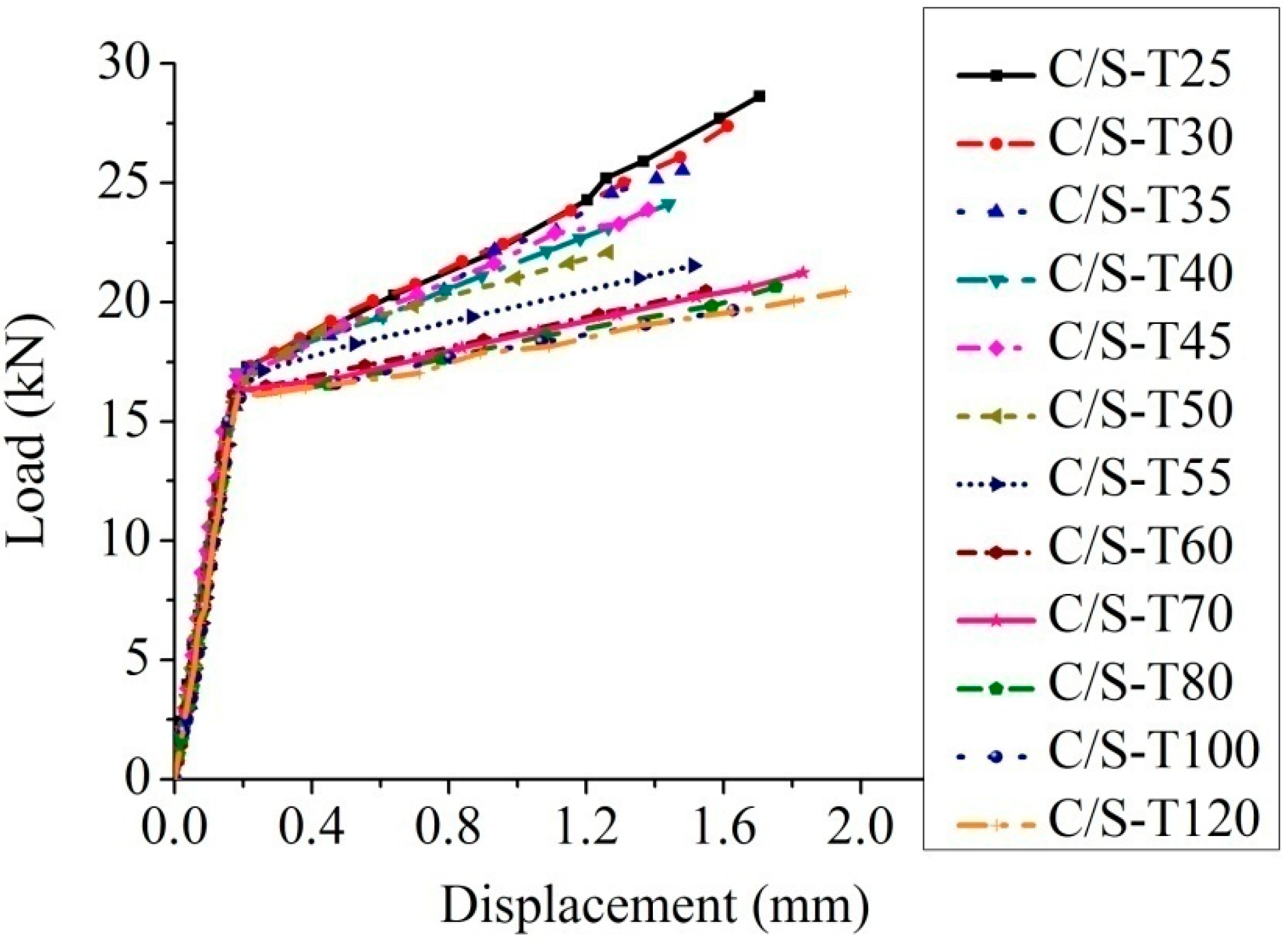
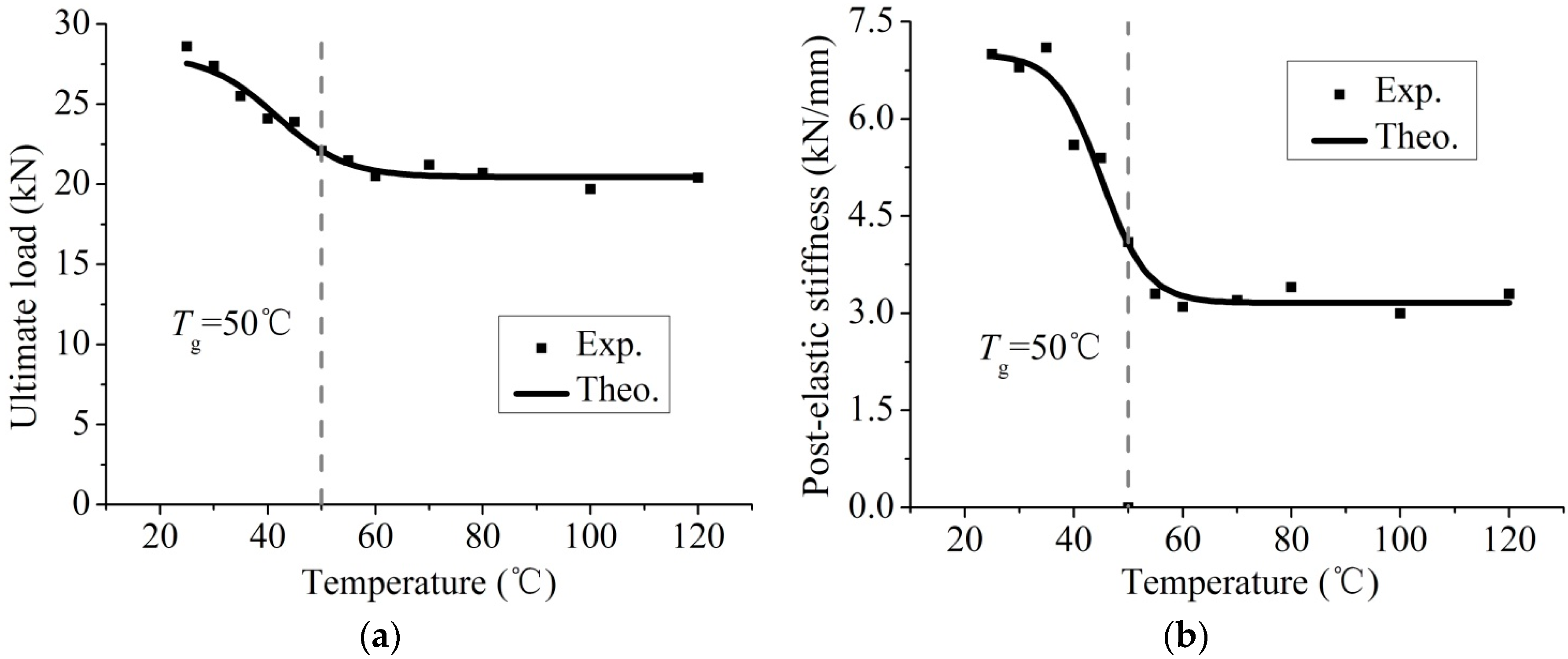
3.2.3. Effects of Temperature

4. Analytical Modeling
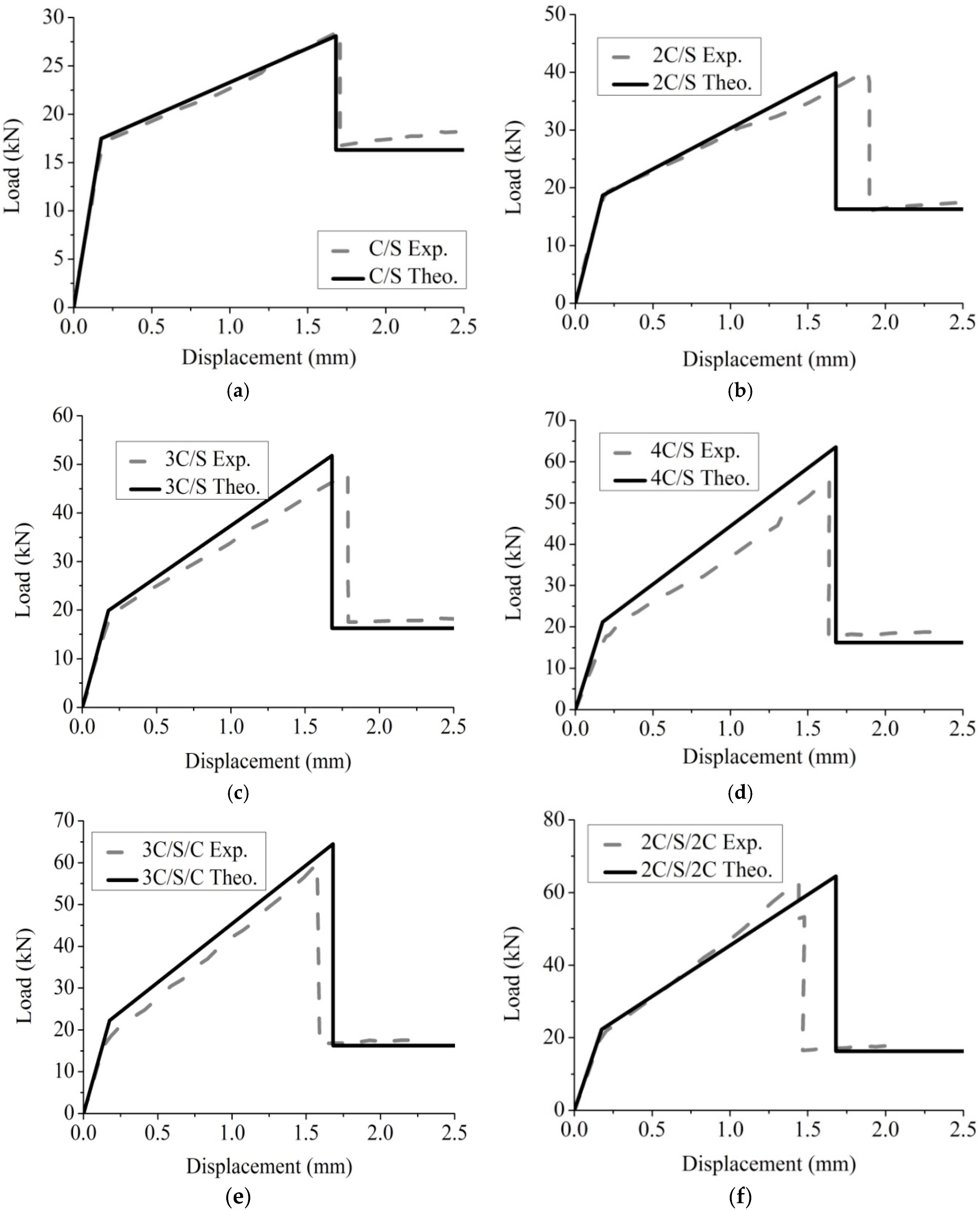
4.1. Analytical Modeling for Tests at Ambient Temperature
4.2. Analytical Modeling for Tests at Elevated Temperatures
5. Conclusions
Acknowledgments
Author Contributions
Conflicts of Interest
References
- Teng, J.G.; Chen, J.F.; Smith, S.T.; Lam, L. Behaviour and strength of FRP-strengthened RC structures: A state-of-the-art review. Proc. Inst. Civ. Eng. Struct. Build. 2003, 156, 51–62. [Google Scholar] [CrossRef]
- Aslam, M.; Shafigh, P.; Jumaat, M.Z.; Shah, S.N.R. Strengthening of RC beams using prestressed fiber reinforced polymers—A review. Constr. Build. Mater. 2015, 82, 235–256. [Google Scholar] [CrossRef]
- Zhao, X.; Zhang, L. State-of-the-art review on FRP strengthened steel structures. Eng. Struct. 2007, 29, 1808–1823. [Google Scholar] [CrossRef]
- Teng, J.G.; Yu, T.; Fernando, D. Strengthening of steel structures with fiber-reinforced polymer composites. J. Constr. Steel Res. 2012, 78, 131–143. [Google Scholar] [CrossRef]
- Sen, R.; Liby, L.; Mullins, G. Strengthening steel bridge sections using CFRP laminates. Compos. Eng. 2001, 32, 309–322. [Google Scholar] [CrossRef]
- Al-Saidy, A.H.; Klaiber, F.W.; Wipf, T.J. Strengthening of steel–concrete composite girders using carbon fiber reinforced polymer plates. Constr. Build. Mater. 2007, 21, 295–302. [Google Scholar] [CrossRef]
- Fam, A.; MacDougall, C.; Shaat, A. Upgrading steel–concrete composite girders and repair of damaged steel beams using bonded CFRP laminates. Thin Wall. Struct. 2009, 47, 1122–1135. [Google Scholar] [CrossRef]
- Schnerch, D.; Rizkalla, S. Flexural strengthening of steel bridges with high modulus CFRP strips. J. Bridge. Eng. 2008, 2, 192–201. [Google Scholar] [CrossRef]
- Miller, T.C.; Chajes, M.J.; Mertz, D.R.; Hastings, J.N. Strengthening of a steel bridge girder using CFRP plates. J. Bridge. Eng. 2001, 6, 514–522. [Google Scholar] [CrossRef]
- Colombi, P.; Poggi, C. Strengthening of tensile steel members and bolted joints using adhesively bonded CFRP plates. Constr. Build. Mater. 2006, 20, 22–33. [Google Scholar] [CrossRef]
- Al-Zubaidy, H.; Al-Mahaidi, R.; Zhao, X. Experimental investigation of bond characteristics between CFRP fabrics and steel plate joints under impact tensile loads. Compos. Struct. 2012, 94, 510–518. [Google Scholar] [CrossRef]
- Bocciarelli, M.; Colombi, P.; Fava, G.; Poggi, C. Fatigue performance of tensile steel members strengthened with CFRP plates. Compos. Struct. 2009, 87, 334–343. [Google Scholar] [CrossRef]
- Liu, H.; Al-Mahaidi, R.; Zhao, X. Experimental study of fatigue crack growth behaviour in adhesively reinforced steel structures. Compos. Struct. 2009, 90, 12–20. [Google Scholar] [CrossRef]
- Li, Y.; Wang, Y.; Ou, J. Mechanical behavior of BFRP-steel composite plate under axial tension. Polymers 2014, 6, 1862–1876. [Google Scholar] [CrossRef]
- Tavakkolizadeh, M.; Saadatmanesh, H. Strengthening of steel-concrete composite girders using carbon fiber reinforced polymers sheets. J. Struct. Eng. 2003, 129, 30–40. [Google Scholar] [CrossRef]
- Lu, Y.; Zhang, H.; Liu, S. Experimental study on tensile properties of steel plate bonded by CFRP. J. Wuhan Univ. Technol. Mater. Sci. Ed. 2008, 23, 727–732. [Google Scholar] [CrossRef]
- Suli, L. Experimental Research on Mechanism of Bond between Carbon Fiber Reinforced Polymer and Steel Plate. Master’s Thesis, Wuhan University, Wuhan, China, November 2004. [Google Scholar]
- Cree, D.; Gamaniouk, T.; Loong, M.L.; Green, M.F. Tensile and lap-splice shear strength properties of CFRP composites at high temperatures. J. Compos. Constr. 2014. [Google Scholar] [CrossRef]
- Cao, S.; Wu, Z.; Wang, X. Tensile properties of CFRP and hybrid FRP composites at elevated temperatures. J. Compos. Mater. 2009, 43, 315–330. [Google Scholar]
- Mouritz, A.P.; Gibson, A.G. Fire Properties of Polymer Composite Materials; Springer: Dordrecht, The Netherlands, 2006; pp. 175–180. [Google Scholar]
- Chowdhury, E.U.; Eedson, R.; Bisby, L.A.; Green, M.F.; Benichou, N. Mechanical characterization of fibre reinforced polymers materials at high temperature. Fire. Technol. 2011, 47, 1063–1080. [Google Scholar] [CrossRef]
- Nguyen, T.; Bai, Y.; Zhao, X.; Al-Mahaidi, R. Mechanical characterization of steel/CFRP double strap joints at elevated temperatures. Compos. Struct. 2011, 93, 1604–1612. [Google Scholar] [CrossRef]
- Li, G.; Wang, P. Advanced Analysis and Design for Fire Safety of Steel Structures; Springer: New York, NY, USA, 2013; pp. 48–50. [Google Scholar]
- Metallic Materials—Tensile Testing—Part 1: Method of Test at Room Temperature; ISO 6892-1:2009; BSI: London, UK, 2009.
- Standard Test Method for Tensile Properties of Polymer Matrix Composite Materials; ASTM D3039-07; ASTM: West Conshohocken, PA, USA, 2008.
- Campbell, F.C. Structural Composite Materials; ASM International: Materials Park, OH, USA, 2010; p. 49. [Google Scholar]
- Tan, K.H.; Zhou, Y. Performance of FRP-strengthened beams subjected to elevated temperatures. J. Compos. Constr. 2011, 15, 304–311. [Google Scholar] [CrossRef]
- Qingrui, Y.; Yongxin, Y. The Application of FRP in Structures' Strengthening and Retrofitting; Chemical Industry Press: Beijing, China, 2006; p. 172. [Google Scholar]
- Kulkarni, R.R.; Chawla, K.K.; Vaidya, U.K.; Koopman, M.C.; Eberhardt, A.W. Characterization of long fiber thermoplastic/metal laminates. J. Mater. Sci. 2008, 43, 4391–4398. [Google Scholar] [CrossRef]
© 2015 by the authors; licensee MDPI, Basel, Switzerland. This article is an open access article distributed under the terms and conditions of the Creative Commons by Attribution (CC-BY) license (http://creativecommons.org/licenses/by/4.0/).
Share and Cite
Lu, Y.; Li, W.; Li, S.; Li, X.; Zhu, T. Study of the Tensile Properties of CFRP Strengthened Steel Plates. Polymers 2015, 7, 2595-2610. https://doi.org/10.3390/polym7121537
Lu Y, Li W, Li S, Li X, Zhu T. Study of the Tensile Properties of CFRP Strengthened Steel Plates. Polymers. 2015; 7(12):2595-2610. https://doi.org/10.3390/polym7121537
Chicago/Turabian StyleLu, Yiyan, Weijie Li, Shan Li, Xiaojin Li, and Tao Zhu. 2015. "Study of the Tensile Properties of CFRP Strengthened Steel Plates" Polymers 7, no. 12: 2595-2610. https://doi.org/10.3390/polym7121537