On the Use of CFRP Sheets for the Seismic Retrofitting of Masonry Walls and the Influence of Mechanical Anchorage

Abstract
:1. Introduction
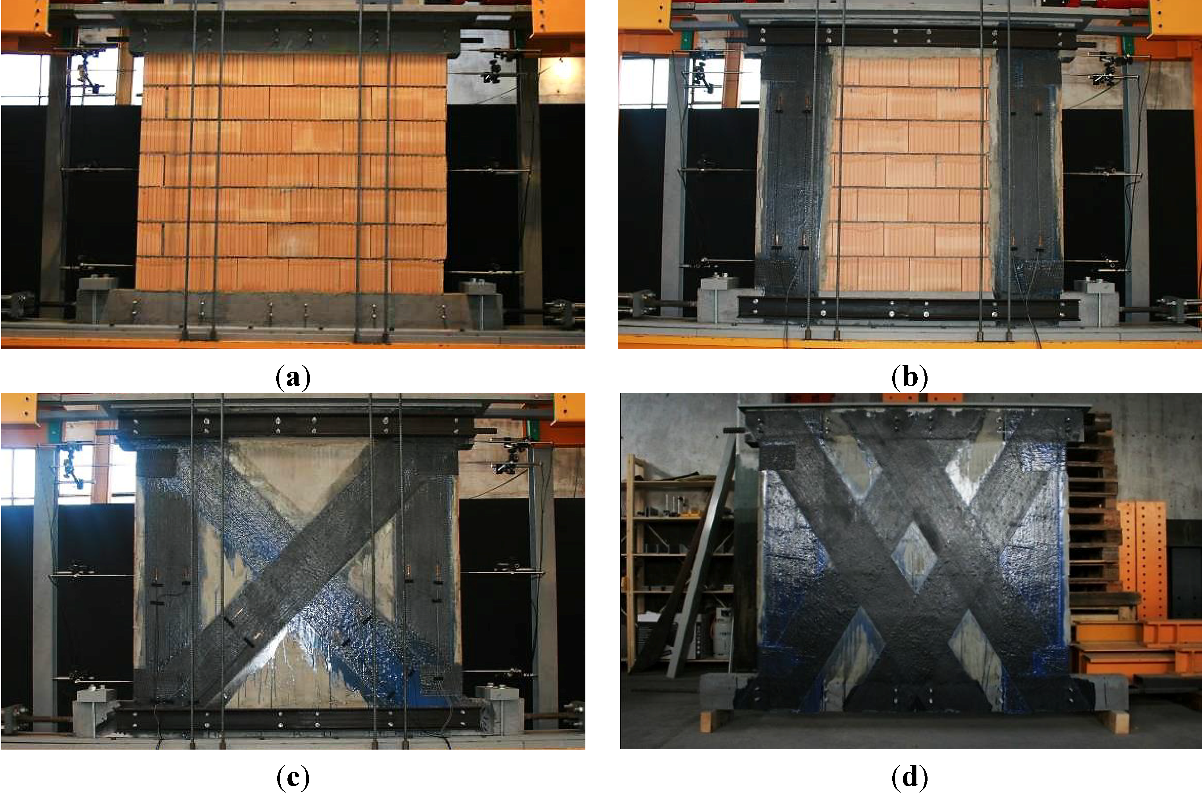
2. The Research Project
2.1. Experimental Series
2.2. Material Properties

| Material | Material Properties | |
|---|---|---|
| Clay brick | Compression strength fbk (N/mm2) | 41.0 |
| Mortar for clay brick | Flexural tension strength ftk after 28 days (N/mm2) | 3.1 |
| Compression strength fmk after 28 days (N/mm2) | 10.2 | |
| CFRP Sheets | S&P C-Sheet 240-200 g/m2 | S&P C-Sheet 240-400 g/m2 |
|---|---|---|
| Elastic modulus E (N/mm2) | 240,000 | 240,000 |
| Elongation at rupture (theoretical) (%) | 1.55 | 1.55 |
| Theoretical ultimate tensile strength fu (N/mm2) | 3,800 1 | 3,800 1 |
| Theoretical design cross section 1 m width (mm/m) | 117 | 234 |
| Adhesive | S&P Resicem | |
| Elastic modulus E at +20°C. (N/mm2) | 4,820 | |
| Tensile strength after 14 days fu (N/mm2) | 22 | |
| Pull off strength on concrete (N/mm2) | >4 (failure in concrete) | |
| Pull off strength on steel (N/mm2) | >10.6 | |
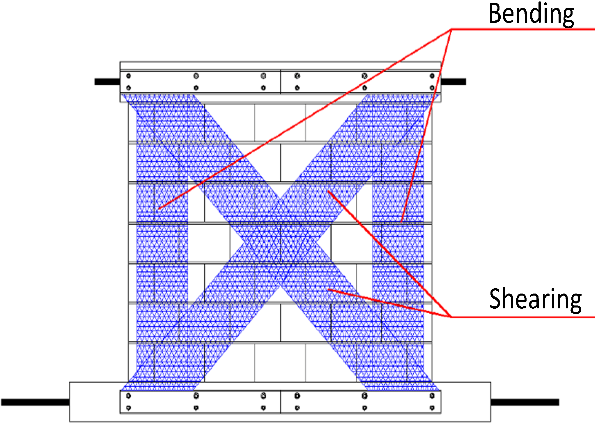
3. Static–Cyclic Shear Tests on Retrofitted Masonry Walls
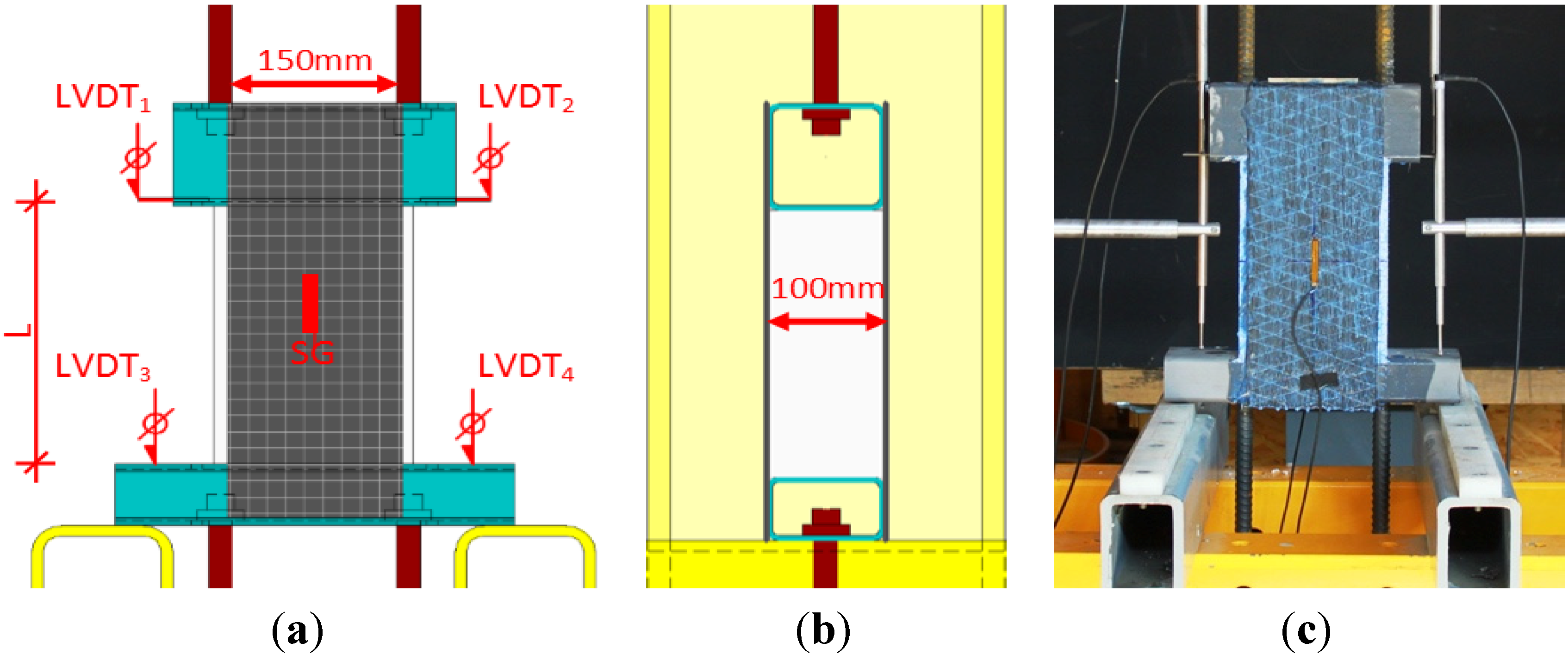
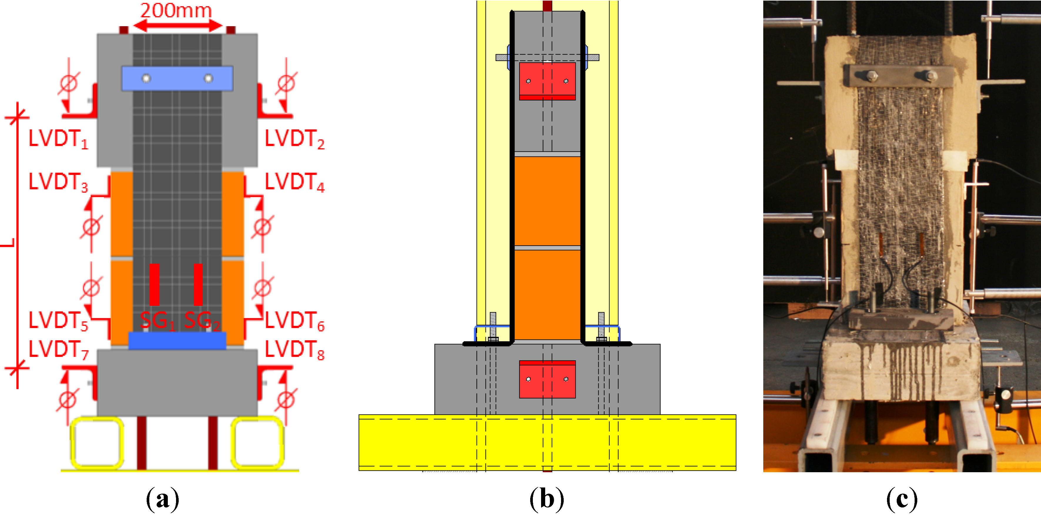
3.1. Test Set-Up
- Firstly, a vertical load of 135 kN, corresponding to a distributed load of 0.5 N/mm2, was applied by two hydraulic actuators with a capacity of 1000 kN each. This vertical load was kept approximately constant during the entire test. The difference of the medium vertical load caused by cyclic horizontal loading was 0.1 N/mm2 maximum.
- Secondly, a horizontal load was applied by two actuators with a capacity of +200/−300 kN each. Both were independently connected to an individual hydraulic system. The horizontal force was progressively and alternatively increased on each side, until the first crack occurred. The test was then driven by deformation until the ultimate limit state was reached and complete failure occurred.
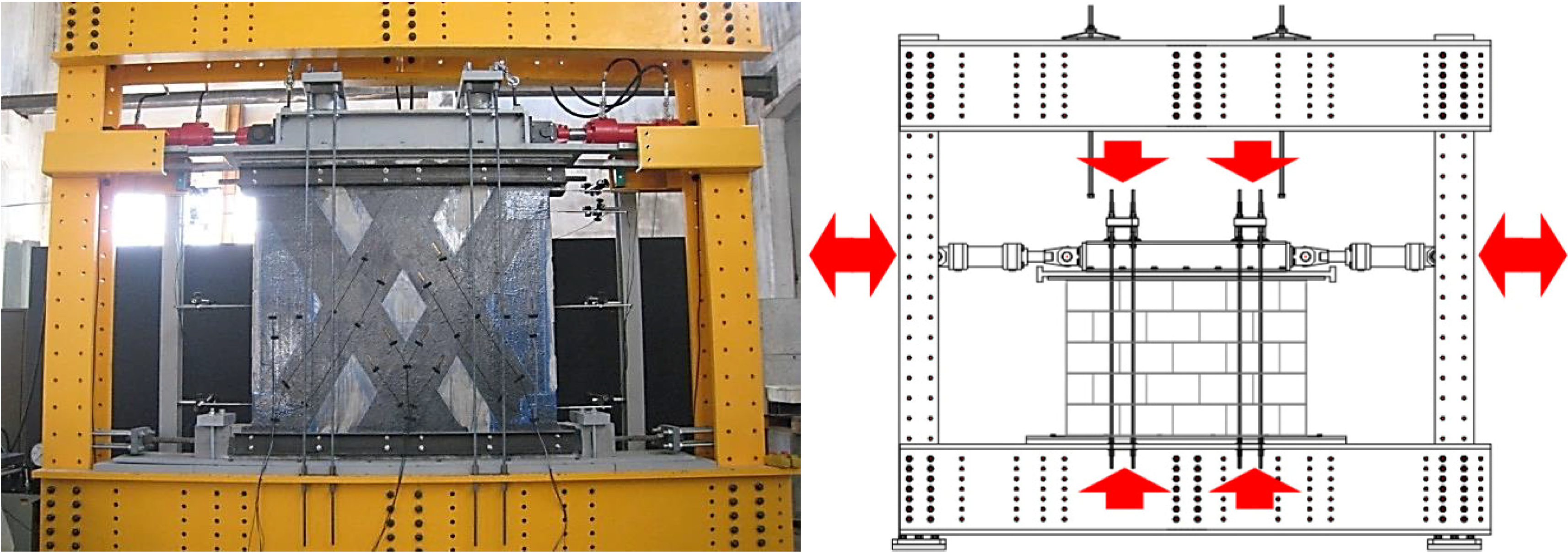
- Two pressure sensors on both hydraulic systems
- Two load cells on the horizontal cylinders
- Several displacement measurements by linear variable differential transformers (LVDT)
- Several strain measurements by means of strain gauges (SG)
3.2. Experimental Program
| Specimen | Type of CFRP Sheet | Retrofit Configuration |
|---|---|---|
| MR-B1 | - | Reference wall, no retrofit |
| MR-B2 | C-sheets 200 g/m2 | Two vertically bonded CFRP sheets |
| MR-B3 | C-sheets 200 g/m2 | Two vertically and two diagonally (45°) bonded CFRP sheets |
| MR-B4 | C-sheets 400 g/m2 | Two vertically and two diagonally (45°) bonded CFRP sheets |
| MR-B5 | C-sheets 200 g/m2 | Two vertically and four diagonally (60°) bonded CFRP sheets |

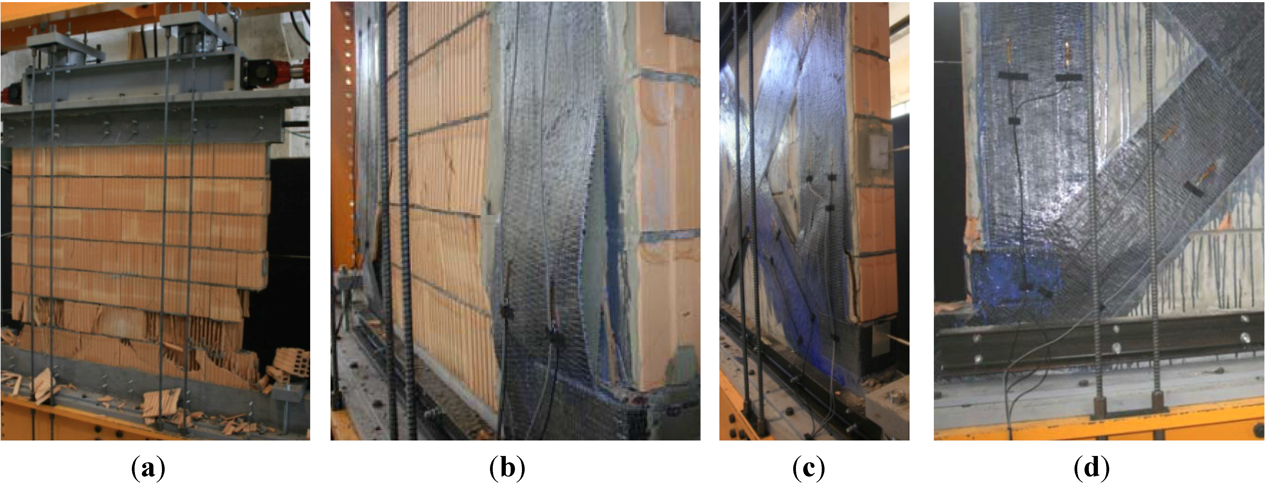
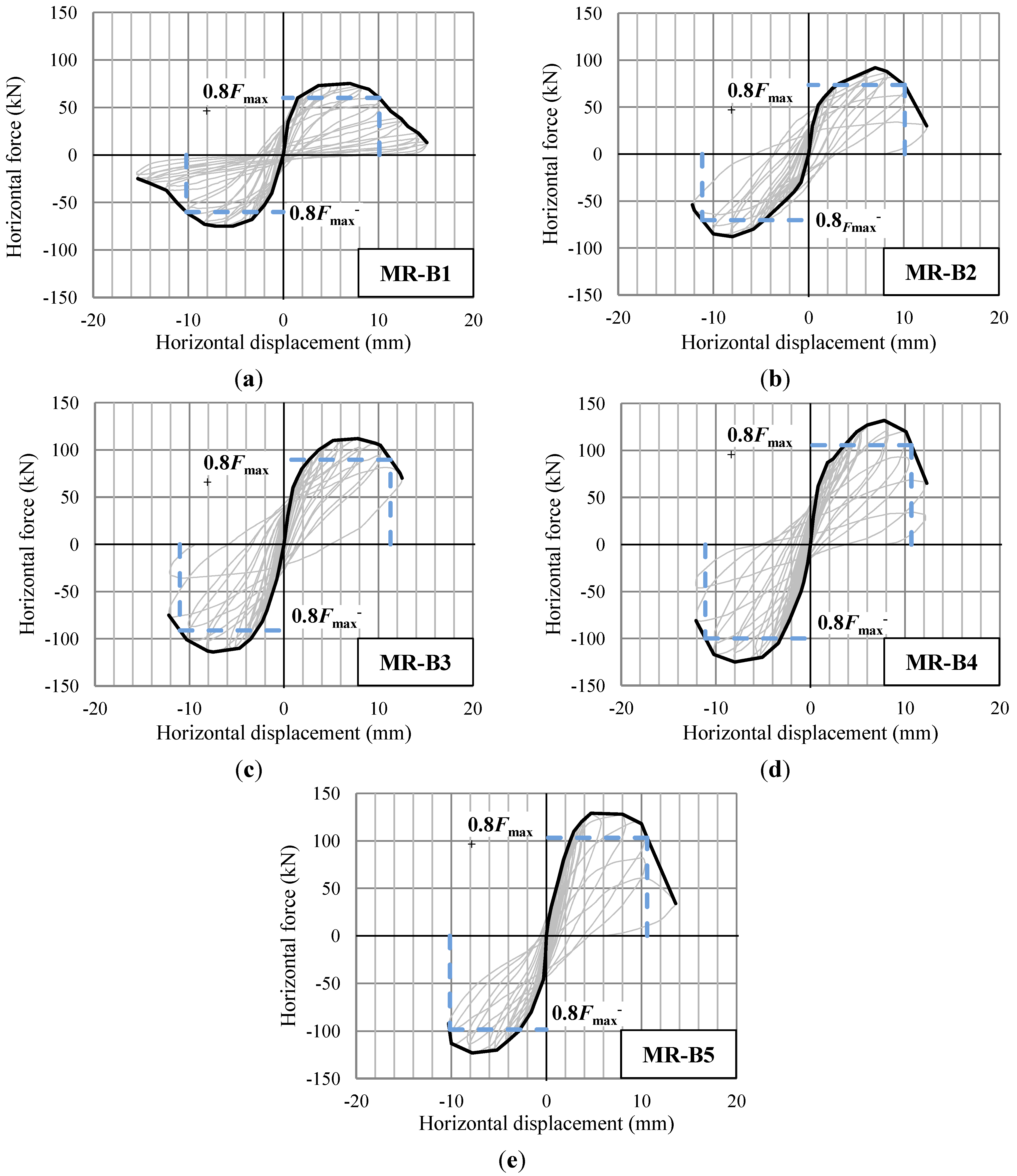
3.3. Test Results
| Specimen | Fmax+ (kN) | Fmax− (kN) | Comparison to Reference Wall | 0.8Fmax+ (kN) | 0.8Fmax− (kN) | δu+ (mm) | δu- (mm) | Comparison to Reference Wall |
|---|---|---|---|---|---|---|---|---|
| MR-B1 | 75.2 | 76.8 | 100% | 60.2 | 61.4 | 10.1 | 10.2 | 100% |
| MR-B2 | 91.7 | 89.0 | 119% | 73.4 | 71.2 | 10.1 | 11.2 | 105% |
| MR-B3 | 111.9 | 113.7 | 148% | 89.5 | 91.0 | 11.3 | 11.0 | 110% |
| MR-B4 | 131.8 | 125.3 | 169% | 105.4 | 100.2 | 10.7 | 11.1 | 107% |
| MR-B5 | 129.9 | 125.0 | 168% | 103.9 | 100.0 | 10.6 | 10.1 | 102% |


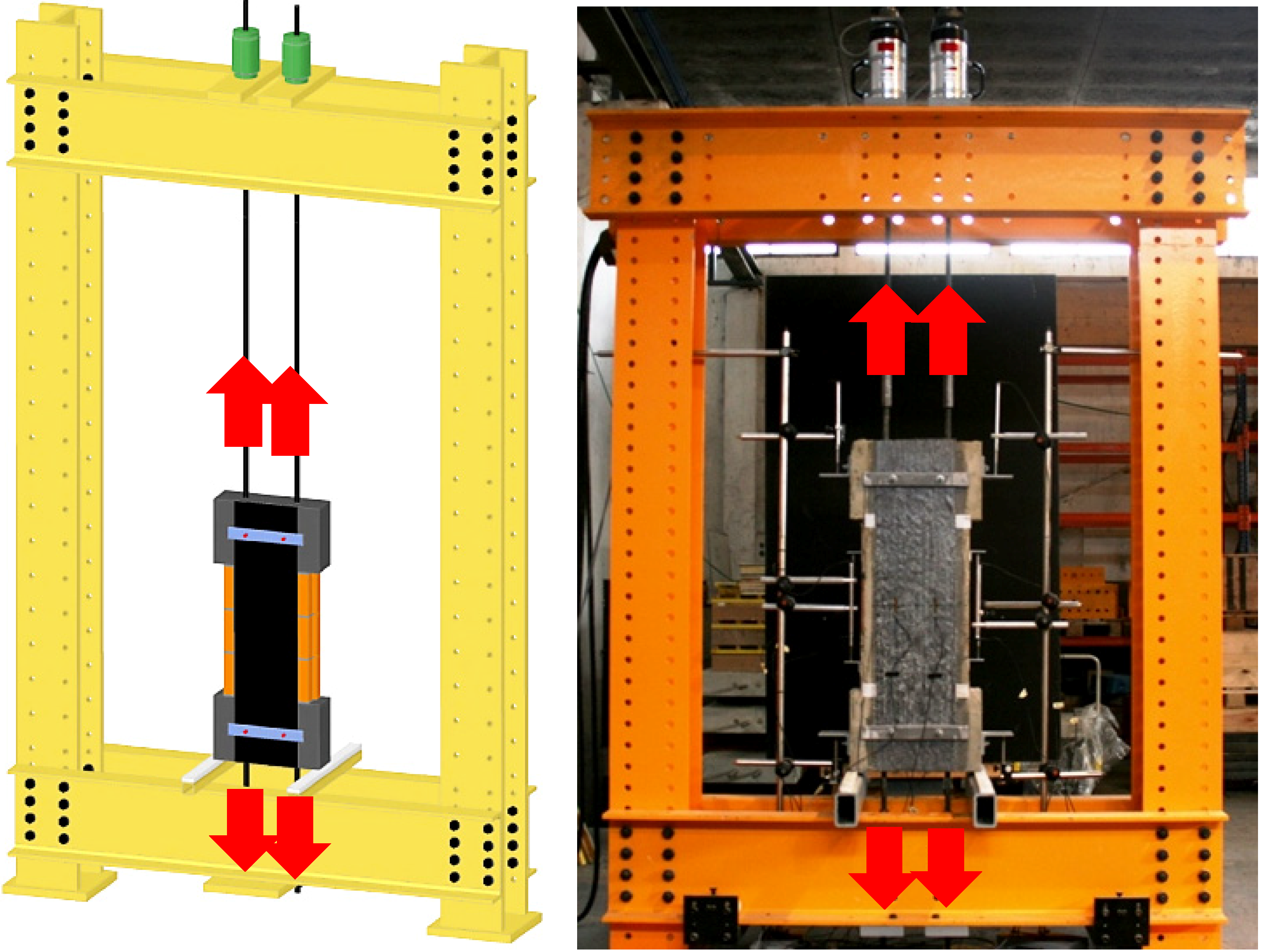
4. Influence of Mechanical Anchorage
4.1. Implementation
4.2. Experimental Studies
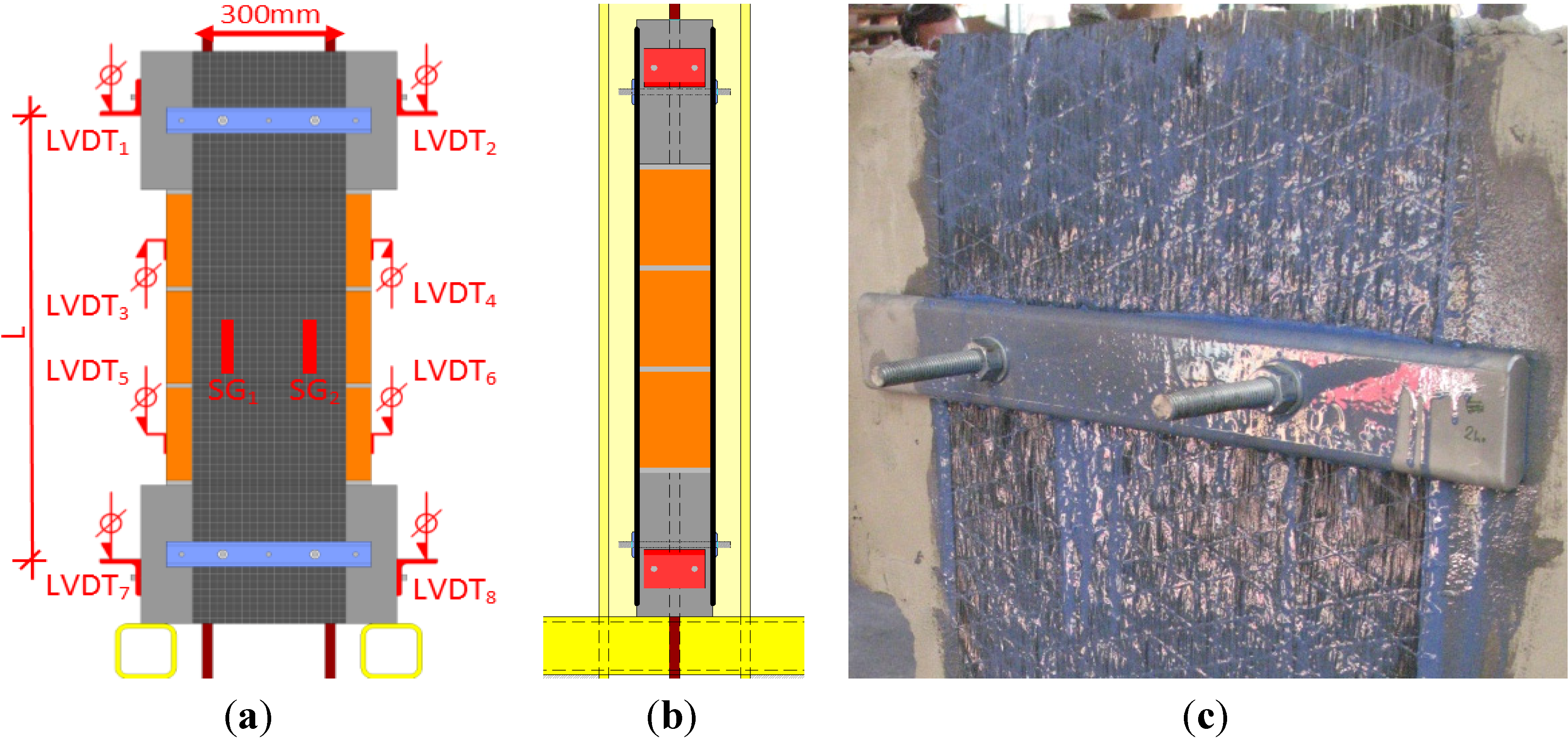
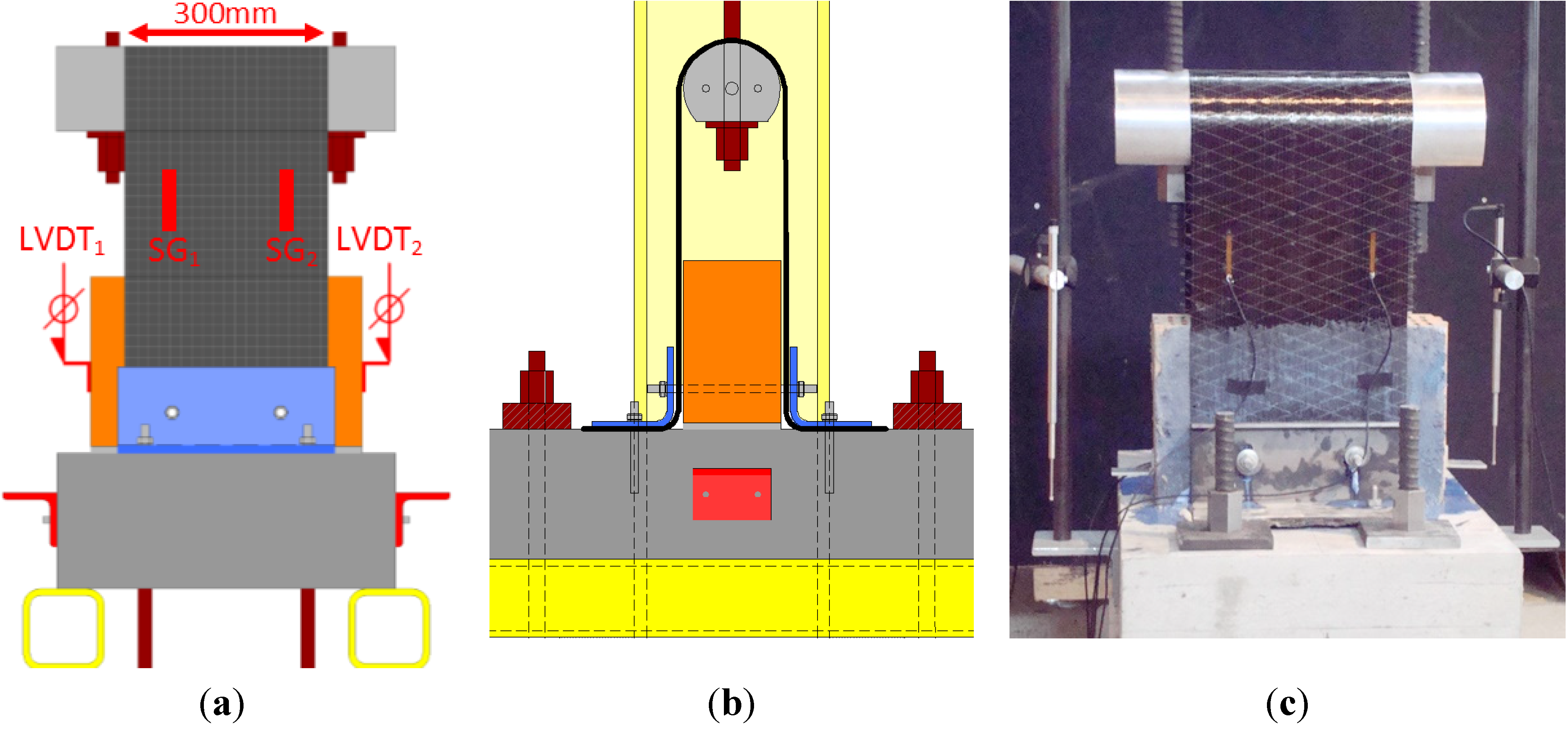
4.2.1. Test Set-Up

4.2.2. Series AT-H
Experimental Program
| Specimen | Type of C-Sheet | Anchorage Profile (Lower RHS Profile) | Bonded Length (mm) |
|---|---|---|---|
| AT-H1 | 240-200 g/m2 | RHS 100/60/5 (width/height/thickness) | 45.0 |
| AT-H2 | 240-200 g/m2 | RHS 100/60/5 | 45.0 |
| AT-H3 | 240-200 g/m2 | RHS 100/100/5 | 85.0 |
| AT-H4 | 240-200 g/m2 | RHS 100/100/5 | 85.0 |
| AT-H9 | 240-400 g/m2 | RHS 100/60/6.3 | 41.1 |
| AT-H10 | 240-400 g/m2 | RHS 100/60/6.3 | 41.1 |
| AT-H11 | 240-400 g/m2 | RHS 100/100/6.3 | 81.1 |
| AT-H12 | 240-400 g/m2 | RHS 100/100/6.3 | 81.1 |
Test Results
| Specimen | Fmax (kN) | Fmax/Ru 1 (−) | σmax (N/mm2) | δ(Fmax) 2 (mm) | ε(Fmax) 3 (%) |
|---|---|---|---|---|---|
| AT-H1 | 51 | 0.38 | 1442 | 1.3 | 0.49% |
| AT-H2 | 71 | 0.53 | 2022 | 2.0 | 0.75% |
| AT-H3 | 62 | 0.47 | 1772 | 1.6 | 0.60% |
| AT-H4 | 70 | 0.53 | 2002 | 1.3 | 0.49% |
| AT-H9 | 120 | 0.45 | 1715 | 1.8 | 0.68% |
| AT-H10 | 138 | 0.52 | 1972 | 2.0 | 0.75% |
| AT-H11 | 137 | 0.51 | 1956 | 1.6 | 0.60% |
| AT-H12 | 110 | 0.41 | 1572 | 1.6 | 0.60% |
4.2.3. Series AT-F
Experimental Program

| Specimen | Type of C-Sheet | Anchorage Profile | Bonded Length (mm) |
|---|---|---|---|
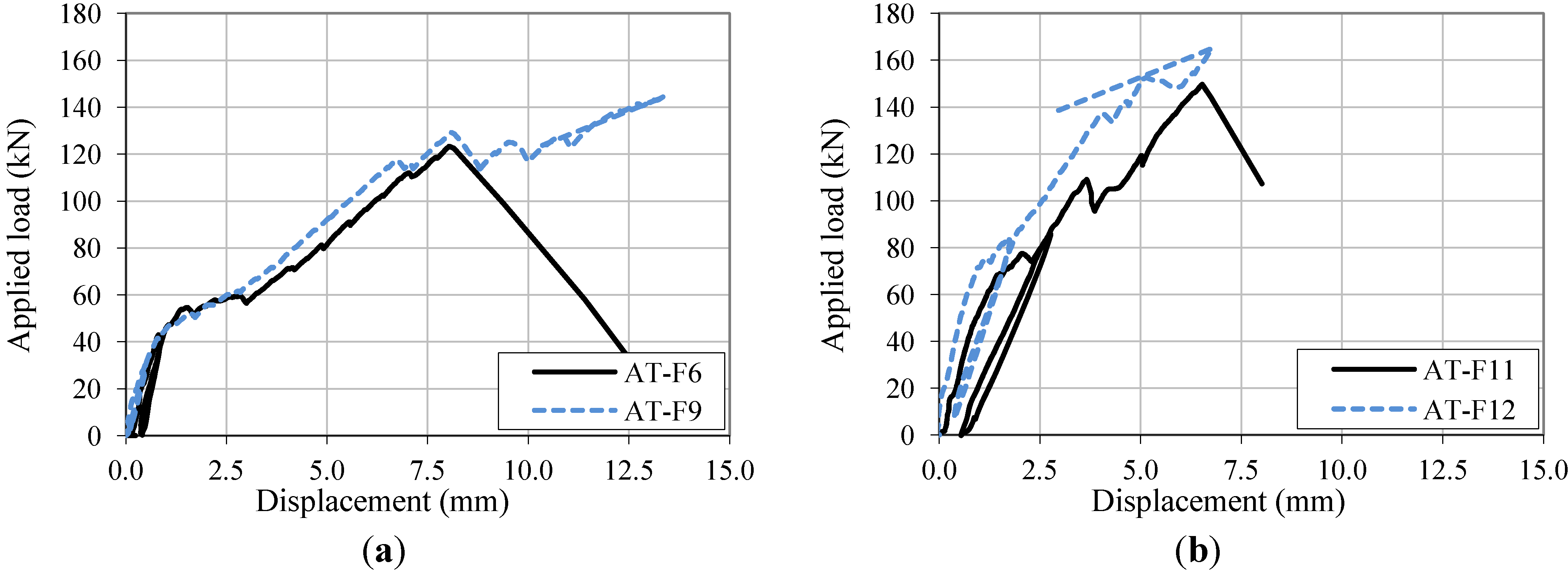
| AT-F6 | 240-200 g/m2 | S&P Aluminum profile | 40.0 |
| AT-F9 | 240-200 g/m2 | S&P Aluminum profile | 40.0 |
| AT-F11 | 240-400 g/m2 | S&P Aluminum profile | 40.0 |
| AT-F12 | 240-400 g/m2 | S&P Aluminum profile | 40.0 |
Test Results
| Specimen | Fmax (kN) | Fmax/Ru 1 (−) | σmax (N/mm2) | δ(Fmax) 2 (mm) | ε(Fmax) 3 (%) |
|---|---|---|---|---|---|
| AT-F6 | 123 | 0.46 | 1757 | 8.0 | 0.85% |
| AT-F9 | 145 | 0.54 | 2059 | 13.4 | 1.43% |
| AT-F11 | 150 | 0.28 | 1066 | 6.5 | 0.69% |
| AT-F12 | 165 | 0.31 | 1174 | 6.8 | 0.72% |


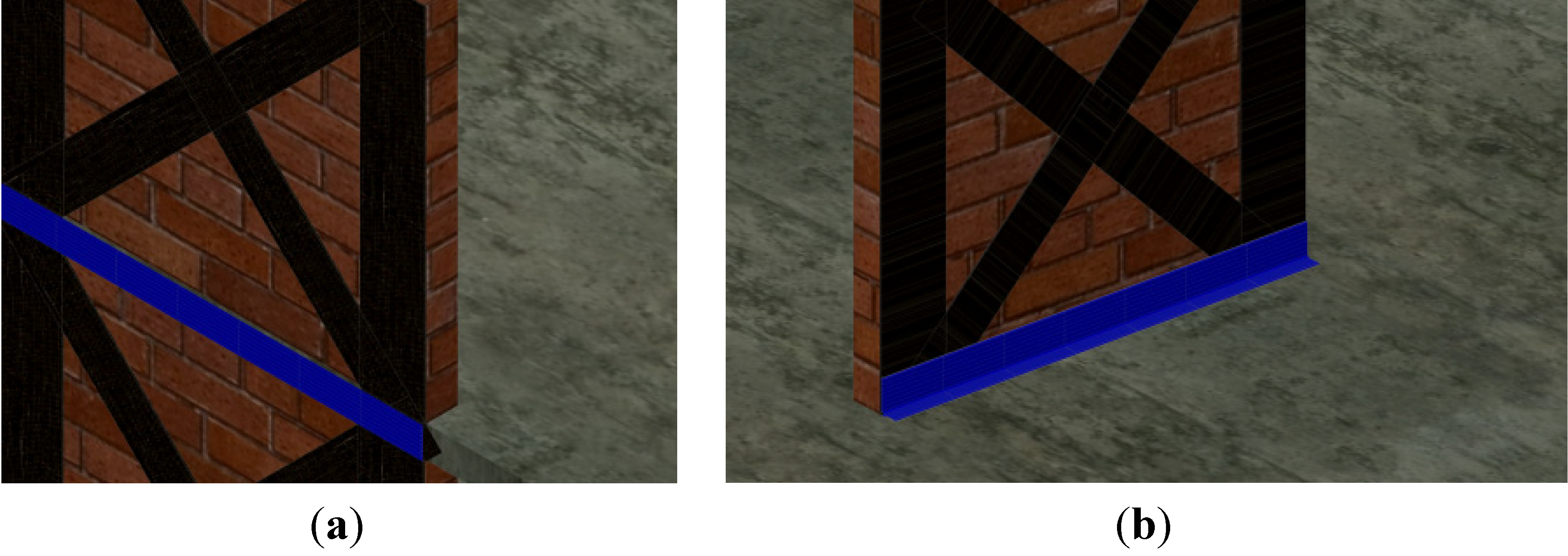
4.2.4. Series AT-C
Experimental Program

| Specimen | Type of C-Sheet | Anchorage Profile | Curvature Radius (mm) | Vertical Anchorage in Slab | Horizontal Anchorage in Brick |
|---|---|---|---|---|---|
| AT-C1 | 240-200 g/m2 | RHS 60/60/5 | 10.0 | 2xM12 | - |
| AT-C2 | 240-200 g/m2 | RHS 120/120/5 | 10.0 | 2xM12 | 2xM12 |
| AT-C3 | 240-400 g/m2 | RHS 120/120/5 | 10.0 | 2xM16 | 2xM12 |
| AT-C4 | 240-400 g/m2 | RHS 120/120/8 | 16.0 | 2xM16 | 2xM12 |
| AT-C5 | 240-200 g/m2 | LNP 150/100/10 | - | 2xM12 | 2xM12 |
| AT-C6 | 240-200 g/m2 | LNP 200/100/10 | - | 2xM12 | 2xM12 |
| AT-C7 | 240-400 g/m2 | LNP 150/100/10 | - | 3xM12 | 2xM12 |
| AT-C8 | 240-400 g/m2 | LNP 200/100/10 | - | 3xM12 | 2xM12 |
| AT-C9 | 240-200 g/m2 | RHS 80/40/8 | 16.0 | 2xM12 encased | - |
Test Results
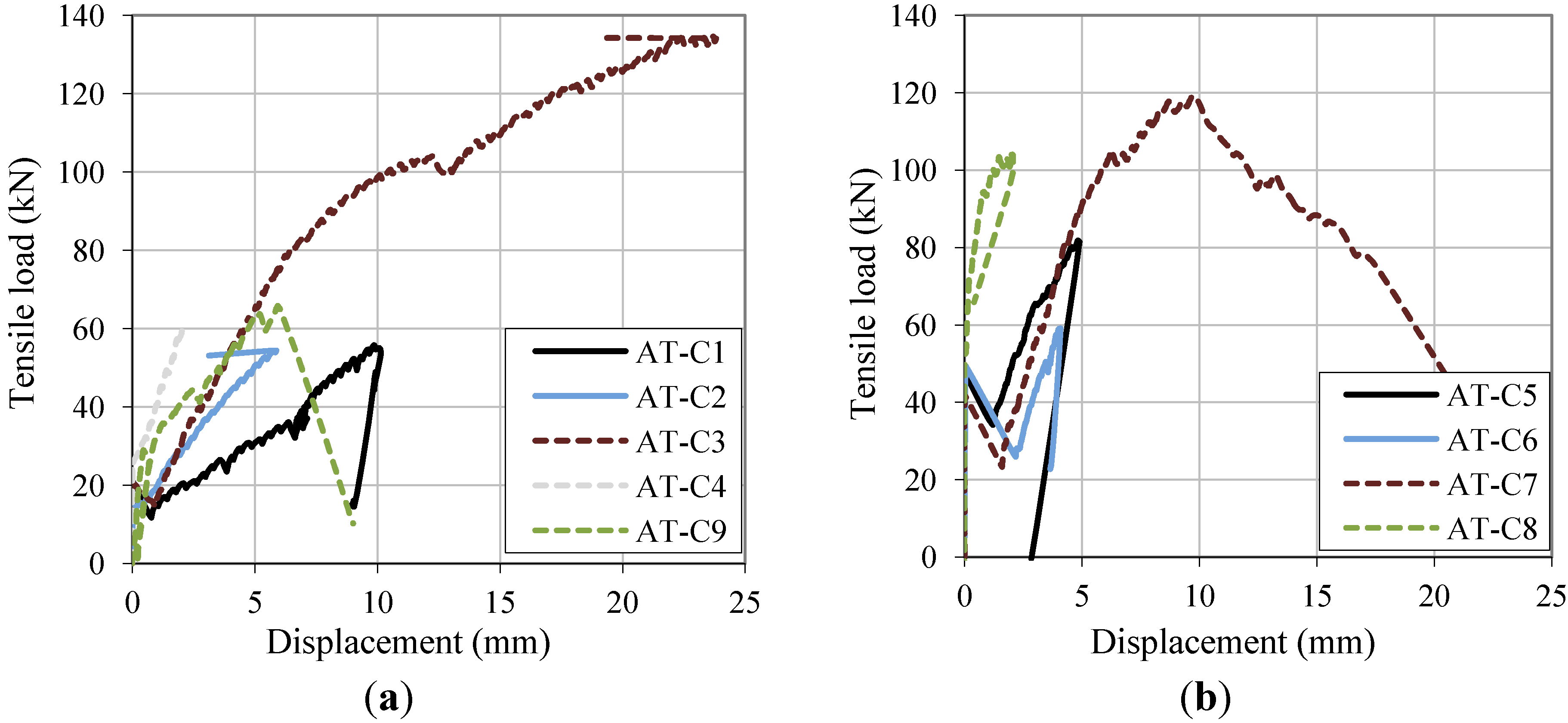
| Specimen | Fmax (kN) | Fmax/Ru 1 (−) | σmax (N/mm2) | δ(Fmax) 2 (mm) |
|---|---|---|---|---|
| AT-C1 | 56 | 0.21 | 795 | 9.9 |
| AT-C2 | 54 | 0.20 | 775 | 5.7 |
| AT-C3 | 136 | 0.25 | 968 | 26.1 |
| AT-C4 | 59 | 0.11 | 423 | 2.0 |
| AT-C5 | 82 | 0.31 | 1166 | 4.8 |
| AT-C6 | 59 | 0.22 | 842 | 4.1 |
| AT-C7 | 119 | 0.22 | 849 | 9.8 |
| AT-C8 | 108 | 0.20 | 741 | 2.0 |
| AT-C9 | 82 | 0.37 | 1407 | 5.9 |
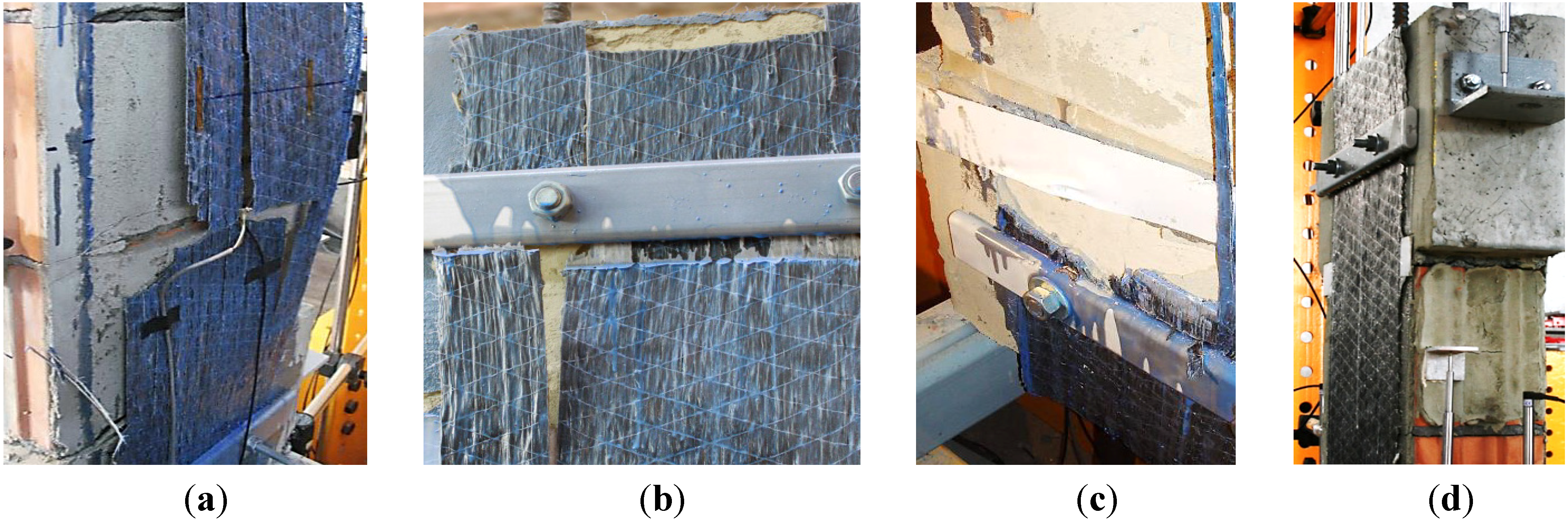
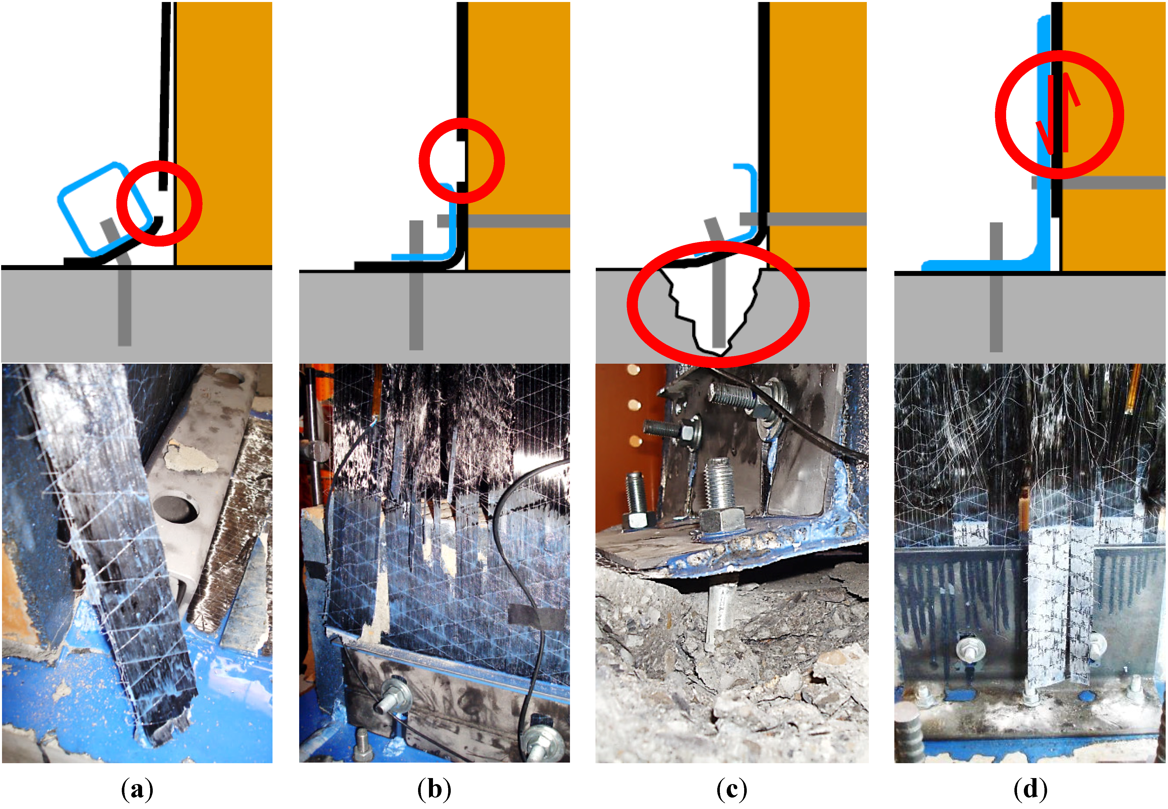
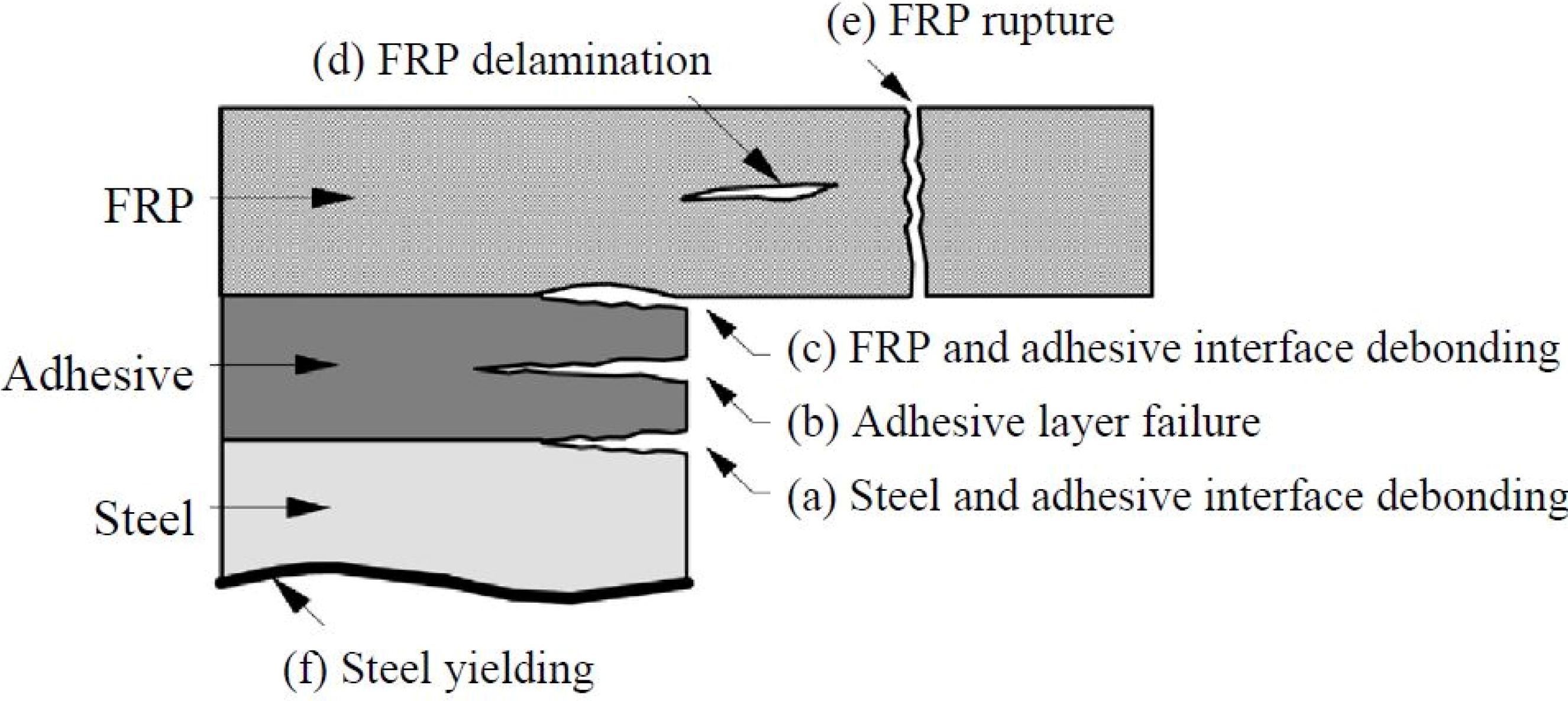
- Rupture of CFRP sheet due to stress concentrations at the curvature (AT-C1), at the edge of the steel profile (AT-C2, AT-C6, AT-C9), or at the edge of the masonry brick (AT-C4, AT-C5):Changes of the fiber direction, edges, or bonding defects (e.g., by adhesive accumulation) causing stress concentrations or non-uniform stress distribution along the CFRP sheet lead to highly loaded fibers and, in most cases, subsequently to premature failure. In specimen AT-C1, failure caused by diverting stresses perpendicular to the fiber direction happened in the curvature of the steel profile. Already little deformation of the mechanical fasteners caused a rotation of the anchoring steel profile. This rotation triggered immediate debonding due to peeling. Numerical analyses on mixed-mode bond behavior of [42] have shown that bond shear capacity already drops drastically with small inclinations. Only the bonded joint between the CFRP sheet and the lower horizontal part of the steel profile allowed a further increase of the applied load. In specimens AT-C2, AT-C4, AT-C5, AT-C6, and AT-C9, edges or bonding defects caused premature CFRP failure.
- Anchorage failure with fracture cone in concrete due to fastener load (specimens AT-C3, AT-C7):the anchorage strength in the concrete can only be enhanced to limited extents, the limited anchorage capacity in the concrete can significantly diminish the performance of mechanical anchorages for retrofitted masonry walls.
- Debonding at vertical part of steel profile (AT-C8):failure occurred unexpectedly early, compared to the experiment results in Series AT-H. Stress concentrations highly influence the bonding behavior and might therefore be the reason for this premature failure.

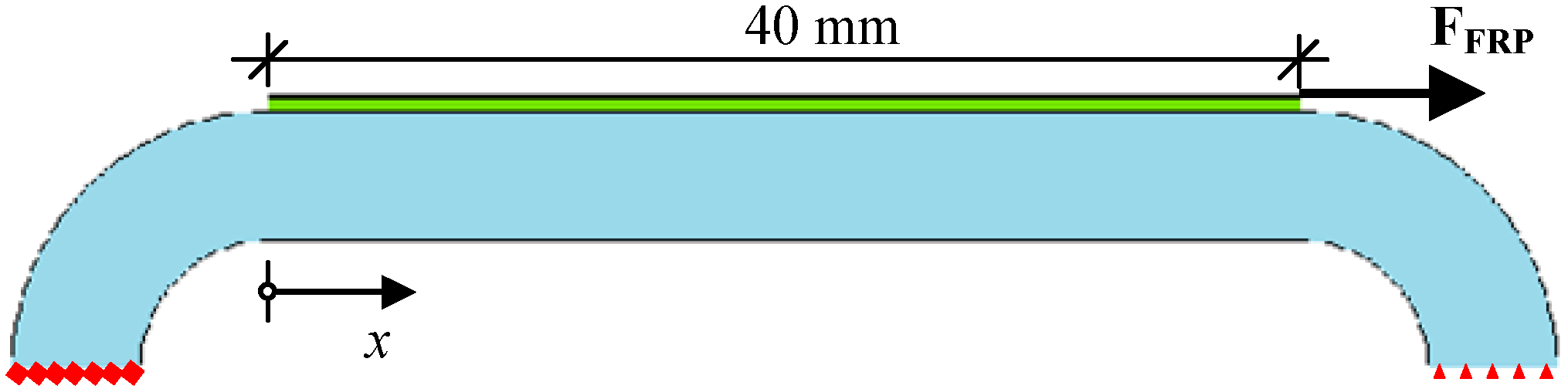
4.3. Analytical Study and Approximate Numerical Investigation
4.3.1. CFRP-to-Steel Bonded Joints


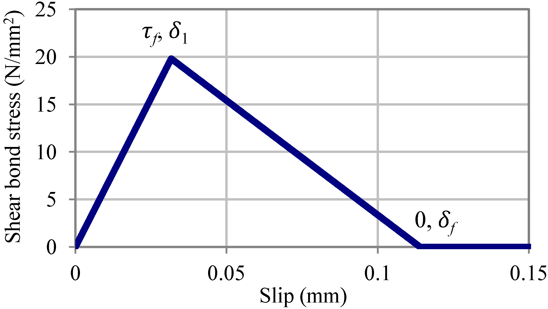
 , with Ea being the elastic modulus of the adhesive. Hence, the slip at failure δf for linear adhesives can easily be derived by using the form of the bilinear bond-slip model: δf = 2Gf/τf.
4.3.2. Basic Numerical Model and Boundary Conditions
4.3.3. Material Modeling
- Tensile strength ft,a = 22.0 N/mm2
- Peak bond stress τf = 0.9ft,a = 19.8 N/mm2
- Mode I stiffness Knn = Ea/ta = 9640 N/mm3, being the initial slope of the bond-separation model
- Mode II stiffness Kss = Ktt = 3(Ga/ta)0.65 = 625 N/mm3, being the initial slope of the bond-slip model
- Fracture energy GII,F = 1.13 N/mm

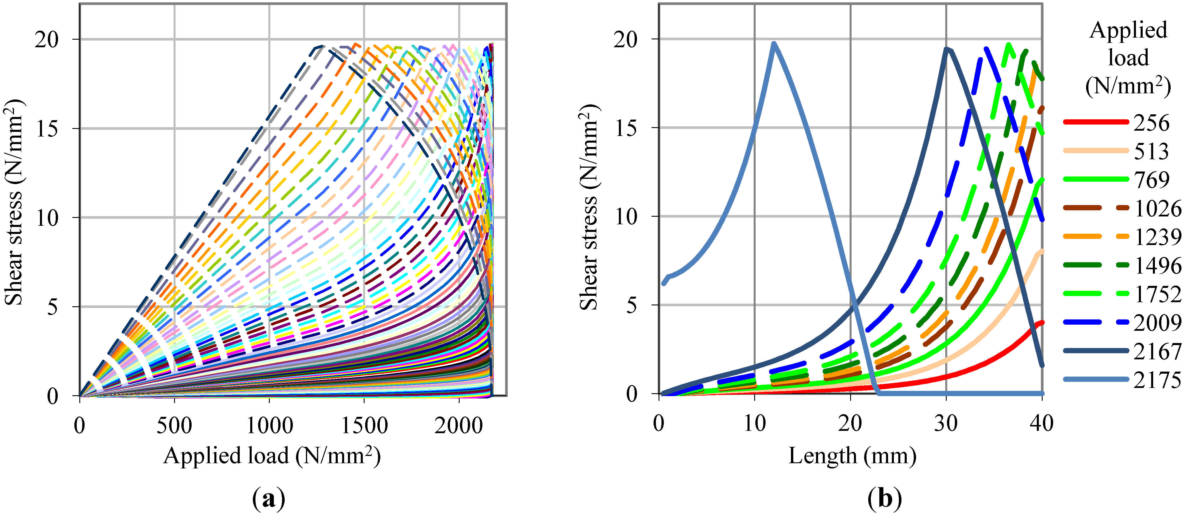
4.3.4. Results of Numerical Simulations

4.4. Comparison between Experimental and Numerical Study
5. Conclusions
Acknowledgments
Author Contributions
Conflicts of Interest
References
- Evaluation Of Earthquake Damaged Concrete And Masonry Wall Buildings: Basic Procedures Manual; FEMA 306; Federal Emergency Management Agency (FEMA): Washington, DC, USA, 1999.
- Paulay, T.; Priestley, M.J.N. Seismic Design of Reinforced Concrete and Masonry Buildings; Wiley: New York, NY, USA, 1992. [Google Scholar]
- Salmanpour, A.; Mojsilovic, N.; Schwartz, J. Deformation capacity of unreinforced masonry walls subjected to in-plane loading: A state-of-the-art review. Int. J. Adv. Struct. Eng. 2013, 5, 1–12. [Google Scholar]
- Binda, L.; Chesi, C.; Parisi, M.A. Seismic damage to churches: Observations from the L’Aquila, Italy, earthquake and considerations on a case-study. Adv. Mater. Res. 2010, 133–134, 641–646. [Google Scholar] [CrossRef]
- Dizhur, D.; Ingham, J.; Moon, L.; Griffith, M.; Schultz, A.; Senaldi, I.; Magenes, G.; Dickie, J.; Lissel, S.; Centeno, J.; et al. Performance of masonry buildings and churches in the 22 February 2011 Christchurch earthquake. Bull. N. Z. Soc. Earthq. Eng. 2011, 44, 279–296. [Google Scholar]
- Gattulli, V. Advanced applications in the field of structural control and health monitoring after the 2009 L’Aquila earthquake. In Engineering Seismology, Geotechnical and Structural Earthquake Engineering; D’Amico, S., Ed.; InTech: Rijeka, Croatia, 2013. [Google Scholar]
- Gattulli, V.; Antonacci, E.; Vestroni, F. Field observations and failure analysis of the Basilica S. Maria di Collemaggio after the 2009 L’Aquila earthquake. Eng. Fail. Anal. 2013, 34, 715–734. [Google Scholar] [CrossRef]
- Augenti, N.; Nanni, A.; Parisi, F. Construction Failures and Innovative Retrofitting. Buildings 2013, 3, 100–121. [Google Scholar] [CrossRef]
- Ceci, A.M.; Contento, A.; Fanale, L.; Galeota, D.; Gattulli, V.; Lepidi, M.; Potenza, F. Structural performance of the historic and modern buildings of the University of L’Aquila during the seismic events of April 2009. Eng. Struct. 2010, 32, 1899–1924. [Google Scholar] [CrossRef]
- Whittaker, A.; Constantinou, M.; Tsopelas, P. Displacement Estimates for Performance-Based Seismic Design. J. Struct. Eng. 1998, 124, 905–912. [Google Scholar] [CrossRef]
- Fardis, M.N. Advances in Performance-Based Earthquake Engineering; Springer: Berlin, Germany, 2010; p. 486. [Google Scholar]
- Tomaževič, M.; Velechovsky, T. Some aspects of testing small-scale masonry building models on simple earthquake simulators. Earthq. Eng. Struct. Dyn. 1992, 21, 945–963. [Google Scholar] [CrossRef]
- Swisscodes for Engineers; Schweizerische Ingenieur-und Architektenverein (SIA): Zurich, Switzerland, 2003.
- Wenk, T. Einführung in die Erdbebenbemessung mit den neuen Tragwerksnormen; Swiss Society for Earthquake Engineering and Structural Dynamics: Zurich, Switzerland, 2004. (In German) [Google Scholar]
- Triantafyllou, S.P.; Chatzi, E.N. A Novel Hysteretic Multiscale Finite Element Method for Nonlinear Dynamic Analysis of Heterogeneous Structures. In Proceedings of the 11th International Conference on Structural Safety & Reliability, Columbia University, New York, NY, USA, 16–20 June 2014.
- Parisi, F.; Augenti, N. Uncertainty in Seismic Capacity of Masonry Buildings. Buildings 2012, 2, 218–230. [Google Scholar] [CrossRef]
- Lourenço, P.; Avila, L.; Vasconcelos, G.; Alves, J.P.; Mendes, N.; Costa, A. Experimental investigation on the seismic performance of masonry buildings using shaking table testing. Bull. Earthq. Eng. 2013, 11, 1157–1190. [Google Scholar] [CrossRef]
- Schwegler, G. Verstärken von Mauerwerk mit Faserverbundwerkstoffen. Ph.D. Thesis, Eidgenössische Technische Hochschule Zürich (ETHZ), Zürich, Switzerland, 1994. [Google Scholar]
- Triantafillou, T. Composites: A New Possibility for the Shear Strengthening of Concrete, Masonry and Wood. Compos. Sci. Technol. 1998, 3538, 1285–1295. [Google Scholar] [CrossRef]
- ElGawady, M.; Lestuzzi, P.; Badoux, M. In-Plane Seismic Response of URM Walls Upgraded with FRP. J. Compos. Constr. 2005, 9, 524–535. [Google Scholar] [CrossRef]
- ElGawady, M.; Lestuzzi, P.; Badoux, M. Static Cyclic Response of Masonry Walls Retrofitted with Fiber-Reinforced Polymers. J. Compos. Constr. 2007, 11, 50–61. [Google Scholar] [CrossRef]
- Prota, A.; Manfredi, G.; Nardone, F. Assessment of Design Formulas for In-Plane FRP Strengthening of Masonry Walls. J. Compos. Constr. 2008, 12, 643–649. [Google Scholar] [CrossRef]
- Kalali, A.; Kabir, M.Z. Cyclic behavior of perforated masonry walls strengthened with glass fiber reinforced polymers. Sci. Iran. 2012, 19, 151–165. [Google Scholar] [CrossRef]
- Fuggini, C.; Chatzi, E.; Zangani, D. Combining Genetic Algorithms with a Meso-Scale Approach for System Identification of a Smart Polymeric Textile. Comput. Aided Civil Infrastruct. Eng. 2013, 28, 227–245. [Google Scholar] [CrossRef]
- Mojsilović, N.; Kostić, N.; Schwartz, J. Modeling of the behaviour of seismically strengthened masonry walls subjected to cyclic in-plane shear. Eng. Struct. 2013, 56, 1117–1129. [Google Scholar] [CrossRef]
- Triantafillou, T.; Fardis, M. Strengthening of historic masonry structures with composite materials. Mater. Struct. 1997, 30, 486–496. [Google Scholar] [CrossRef]
- Zhuge, Y. FRP-Retrofitted URM Walls under In-Plane Shear: Review and Assessment of Available Models. J. Compos. Constr. 2010, 14, 743–753. [Google Scholar] [CrossRef]
- S&P Clever Reinforcement Company Seismic References/Pictures. Available online: http://www.reinforcement.ch/products/frp-tragwerkverstaerkung/anwendungsbereiche-referenzen/ (accessed on 3 January 2014).
- Suter, R.; Broye, A.; Grisanti, M. Essais de Cisaillement de murs en Maconnerie Renforces, Série Expérimentale Pluriels MR-A, MR-B, MR-C; University of Applied Sciences (UAS): Fribourg, Switzerland, 2010. (In French) [Google Scholar]
- Bischof, P.; Suter, R. Retrofitting Masonry Walls with Carbon Mesh. Polymers 2014, 6, 280–299. [Google Scholar]
- Kalfat, R.; Al-Mahaidi, R.; Smith, S. Anchorage Devices Used to Improve the Performance of Reinforced Concrete Beams Retrofitted with FRP Composites: State-of-the-Art Review. J. Compos. Constr. 2013, 17, 14–33. [Google Scholar]
- Grelle, S.; Sneed, L. Review of Anchorage Systems for Externally Bonded FRP Laminates. Int. J. Concr. Struct. Mater. 2013, 7, 17–33. [Google Scholar]
- Ceroni, F.; Pecce, M.; Matthys, S.; Taerwe, L. Debonding strength and anchorage devices for reinforced concrete elements strengthened with FRP sheets. Compos. Part B 2008, 39, 429–441. [Google Scholar] [CrossRef]
- Nigro, E.; di Ludovico, M.; Bilotta, A. Experimental Investigation of FRP-Concrete Debonding under Cyclic Actions. J. Mater. Civ. Eng. 2011, 23, 360–371. [Google Scholar]
- Fernando, D.; Teng, J.; Yu, T.; Zhao, X. Preparation and Characterization of Steel Surfaces for Adhesive Bonding. J. Compos. Constr. 2013, 17. [Google Scholar] [CrossRef]
- Technical Data Sheet: S&P C-Sheets; S&P Clever Reinforcement Company: Seewen SZ, Switzerland, 2014.
- S&P Resicem Saturating Resin; Lab Report; LPM (Labor für Prüfung und Materialtechnologie): Beinwil am See, Switzerland, 2001.
- Suter, R.; Broye, A. Statisch-zyklische Versuche zum Erdbebenverhalten von Mauerwerkswänden. Available online: http://www.baufachinformation.de/literatur/2011019020243 (accessed on 4 June 2014).
- Guide for the Design and Construction of Externally Bonded FRP Systems for Strengthening URM Structures; American Concrete Institute (ACI) Committee 440: Farmington Hills, MI, USA, 2008.
- Advisory Committee on Technical Recommendations for Construction Guide for the Design and Construction of Externally Bonded FRP Systems for Strengthening Existing Structures; National Research Committee (CNR): Rome, Italy, 2004.
- Fernando, D. Bond Behaviour and Debonding Failures in CFRP-Strengthened Steel Members. Ph.D. Thesis, The Hong Kong Polytechnic University, Hong Kong, 2010. [Google Scholar]
- De Lorenzis, L.; Zavarise, G. Modeling of mixed-mode debonding in the peel test applied to superficial reinforcements. Int. J. Solids Struct. 2008, 45, 5419–5436. [Google Scholar] [CrossRef]
- Zhao, X.-L.; Zhang, L. State-of-the-art review on FRP strengthened steel structures. Eng. Struct. 2007, 29, 1808–1823. [Google Scholar] [CrossRef]
- Xia, S.H.; Teng, J.G. Behavior of FRP-to-Steel Bonded Joints. In International Symposium on Bond Behaviour of FRP in Structures (BBFS 2005); Chen, J.F., Teng, J.G., Eds.; International Institute for FRP in Construction: Hong Kong, 2005; pp. 411–418. [Google Scholar]
- ABAQUS. Abaqus Version 6.10 Documentations Collection; Dassault Systèmes Simulia Corp.: Providence, RI, USA, 2010. [Google Scholar]
- Obaidat, Y.T.; Heyden, S.; Dahlblom, O. The effect of CFRP and CFRP/concrete interface models when modeling retrofitted RC beams with FEM. Compos. Struct. 2010, 92, 1391–1398. [Google Scholar] [CrossRef]
- Bocciarelli, M.; Colombi, P.; Fava, G.; Poggi, C. Prediction of debonding strength of tensile steel/CFRP joints using fracture mechanics and stress based criteria. Eng. Fract. Mech. 2009, 76, 299–313. [Google Scholar] [CrossRef]
© 2014 by the authors; licensee MDPI, Basel, Switzerland. This article is an open access article distributed under the terms and conditions of the Creative Commons Attribution license (http://creativecommons.org/licenses/by/3.0/).
Share and Cite
Bischof, P.; Suter, R.; Chatzi, E.; Lestuzzi, P. On the Use of CFRP Sheets for the Seismic Retrofitting of Masonry Walls and the Influence of Mechanical Anchorage. Polymers 2014, 6, 1972-1998. https://doi.org/10.3390/polym6071972
Bischof P, Suter R, Chatzi E, Lestuzzi P. On the Use of CFRP Sheets for the Seismic Retrofitting of Masonry Walls and the Influence of Mechanical Anchorage. Polymers. 2014; 6(7):1972-1998. https://doi.org/10.3390/polym6071972
Chicago/Turabian StyleBischof, Patrick, René Suter, Eleni Chatzi, and Pierino Lestuzzi. 2014. "On the Use of CFRP Sheets for the Seismic Retrofitting of Masonry Walls and the Influence of Mechanical Anchorage" Polymers 6, no. 7: 1972-1998. https://doi.org/10.3390/polym6071972