1. Introduction
Shear capacity equations proposed by current codes for fiber-reinforced polymer reinforced concrete (FRP-RC) elements stem either from regression-based models, derived from experimental results available in the literature, or from simplified strut-and-tie models with an implicit application of the plasticity theory. None of these formulations is based on mechanical models that aim at capturing the real contributions of all resisting mechanisms to the shear capacity. Formulations belonging to the first group, e.g., ACI 318-08 [
1], give the shear strength as the sum of the maximum contributions of all resisting elements—FRP, stirrups and concrete—while in the second group, e.g., CNR-DT200 [
2], it equals the minimum value between the maximum concrete strength and the sum of FRP and stirrup maximum strengths.
Both approaches, beyond not being rigorous, can lead to overestimating of the shear strength of FRP-strengthened RC elements.
The lack of a mechanical model able to correctly render the interaction between FRP and steel shear reinforcement has been highlighted several times when dealing with the analysis of parameters that affect the shear behavior of FRP-strengthened RC structures.
To this end, Lima and Barros [
3], working on a large database of experimental results collected from the literature, conducted a comparative study aiming at assessing the reliability of the most common shear design models: after comparing the experimental results with the theoretical values, it was pointed out that, in most cases, current equations overestimate the experimentally measured shear capacity.
As a matter of fact, in the last two decades, most research efforts have been devoted to defining the contribution of FRP to shear capacity, however, without developing a comprehensive mechanical model capable of accounting for the interaction of all resisting mechanisms. In this framework, Khalifa
et al. [
4] proposed two design algorithms to compute the contribution of FRP to the shear capacity of RC flexural members: the first one is based on the evaluation of the effective stress that causes the tensile fracture of FRP sheets and the second one on the bond mechanism. However, the overall shear capacity is still expressed as the sum of the contribution of all resisting mechanisms. Triantafillou and Antonopoulos [
5] introduced a design model to evaluate the contribution of FRP to the shear capacity: it is based on the calculation of an effective FRP strain, obtained through calibration with experimental tests and defined as the minimum value among the maximum strain to control the crack opening, the strain corresponding to premature shear failure due to FRP debonding and the strain corresponding to shear failure combined with or followed by FRP tensile fracture. Along this line of research, many models have been proposed, Chen and Teng [
6], Carolin and Taljsten [
7] and Monti and Liotta [
8], with the latter having the merit of expressing the FRP effective stress through a closed-form equation obtained from a mechanics-based analytical model: after the constitutive law of an FRP layer bonded to concrete is defined, the compatibility condition is imposed by the shear crack opening, and then, analytical expressions of the stress field in FRP strips/sheets crossing a shear crack are derived.
Chaallal
et al. [
9] proposed an equation to evaluate the effective strain of FRP based on the total shear-reinforcement ratio
, which yields promising results for a limited range of shear-reinforcement values.
Pellegrino and Modena [
10] presented an analytical model to describe the shear capacity of RC beams that takes into account the interaction between stirrups and FRP: starting from the assumption that the FRP strain equals the stirrups’ strain, the FRP contribution to the shear capacity is obtained by imposing the equilibrium condition between concrete and FRP at failure. The model is based on a weak compatibility condition, since a rough assumption about the strain of all of the stirrups is made: in fact, to account for the unknown value of the stress and strain of all of the stirrups crossing the crack, a reduction coefficient
is introduced. Bukhari
et al. [
11] presented a detailed review of the models proposed by current codes—ACI 2008 and Eurocode 2 [
1,
12]—pointing out that the shear strength so calculated does not match the values of experimental results when considering varied typologies—mechanical and geometrical properties—of structural elements. Even if some limits of the current design approaches are analyzed and the importance of the interaction between steel and FRP is highlighted, a design approach is not proposed. Modifi and Chaallal [
13], after examining all of the parameters that mainly influence the shear behavior of FRP-strengthened RC members and reviewing the role of these parameters in current design codes, suggested a new design method to account for the effect of transverse steel by introducing a cracking modification factor β
c, evaluated as a function of the geometrical ratio of steel and FRP and the respective Young’s moduli.
The approach presented hereafter stems from a mechanical model solved by imposing a strong compatibility condition along the crack between FRP strips/sheets and steel stirrups and an equilibrium condition between tensile and compressive resultant forces. Overall, the proposed model allows predicting the failure sequence of the resisting elements while checking the stress of the concrete strut, but most of all, it allows for a better understanding of the underlying mechanical behavior determining the actual shear resistance of an RC member strengthened in shear with FRP.
2. New Mechanical Model
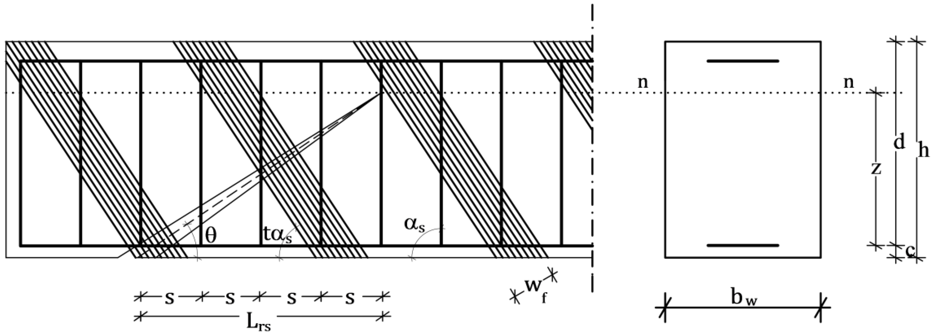
Starting from the model of
Figure 1, which represents the general configuration of an RC cracked beam strengthened in shear with FRP, the simplified model in
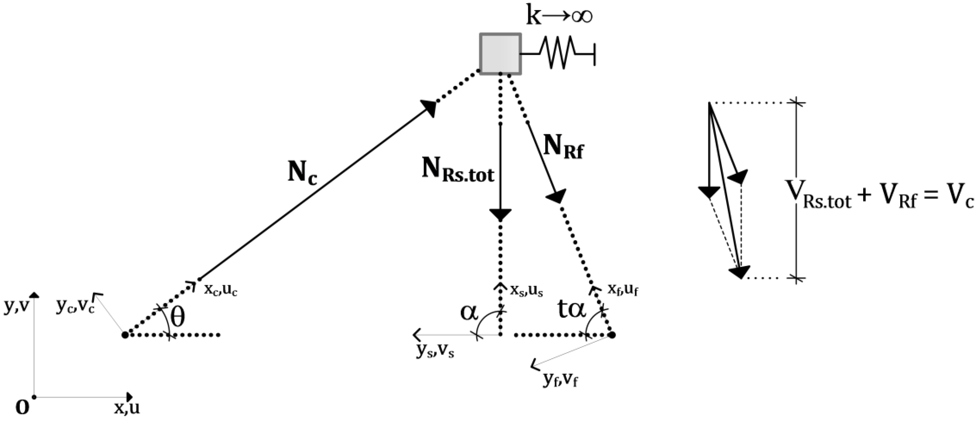
Figure 2 has been defined in order to fulfill the following requirements: (1) reproducing the real mechanical behavior of the structure, with reference to all of the (compressive and tensile) resisting mechanisms and to their stiffness and resistance, for any possible arrangement of the steel tensile bars and FRP strips/sheets; (2) providing a model that can be the basis for a reliable procedure of the design and verification of structural elements, especially referring to the pseudo-ductile behavior of a beam failing in shear; and (3) putting forward a design/verification methodology able to allow the control of the stress in each resisting element.
Since the geometry of the structure and the mechanical characteristics of the materials are given quantities, the solution of the system can be conveniently carried out by imposing a strong compatibility condition along the crack and the equilibrium condition between the compressive and tensile resultant forces. The compatibility condition allows one to calculate the actual strain of each fiber of FRP and each stirrup crossing the crack, from which the corresponding tensile stress can be easily derived. Once the overall acting tensile force is known, the equilibrium condition gives the corresponding compressive force in the concrete strut, whose magnitude will clearly depend on the geometry of the system.
Figure 1.
RC beam strengthened in shear with FRP strips.
Figure 1.
RC beam strengthened in shear with FRP strips.
Figure 2.
Simplified model.
Figure 2.
Simplified model.
In the following sections, it will be firstly shown how the compatibility condition is set along the crack and how it is employed to calculate stress and strain in the FRP, Monti and Liotta [
8] and stirrups, respectively, to derive their actual contribution to the shear capacity. Then, explicitly referring to the simplified mechanical model here proposed, the equilibrium condition is imposed to calculate the stress in the concrete strut.
These three closed form equations expressing the stress of FRP, stirrups and concrete strut as a function of the crack opening γ and the position along the crack x are then employed to solve the mechanical model.
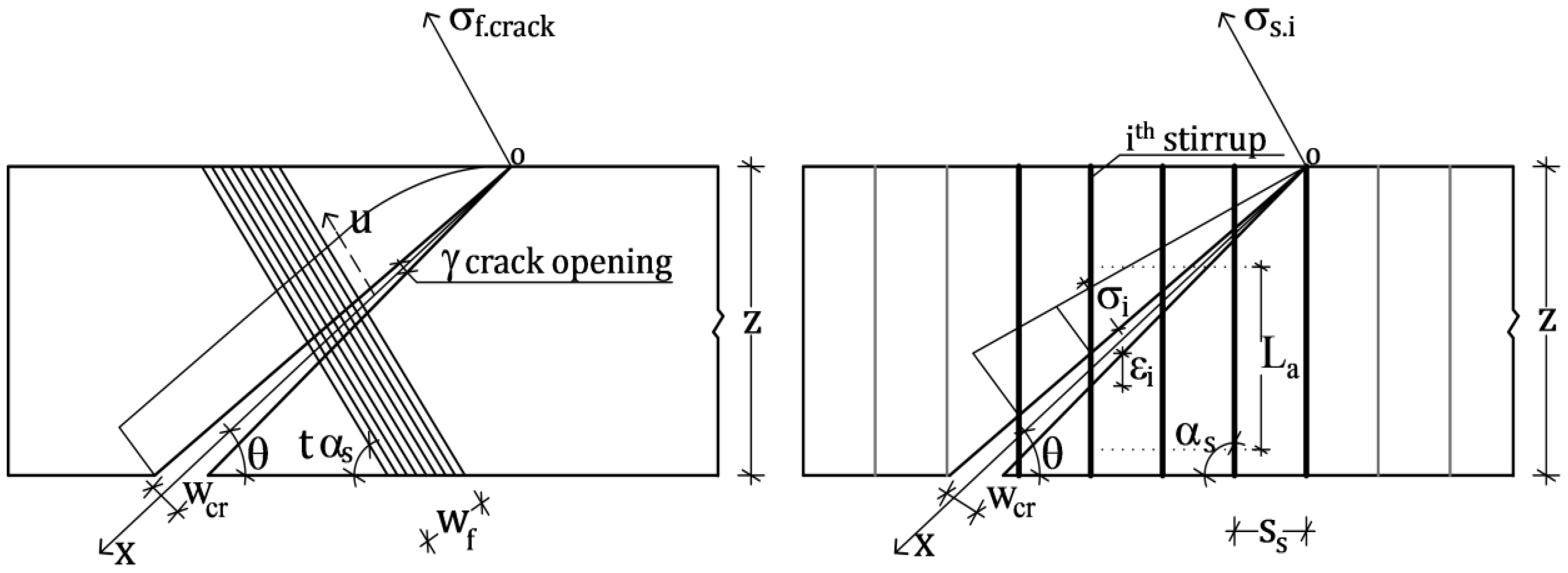
3. Compatibility Condition
Figure 1 shows a typical configuration of a cracked RC beam strengthened in shear with FRP, where two FRP strips and five stirrups cross the crack. At each location along the crack, that is along the
x-axis of the local reference system in
Figure 3, the strain in the FRP strips and in the stirrups change proportionally to the crack width
wcr, which is assumed to vary linearly with
x:
where γ is the crack opening angle.
Figure 3.
Compatibility along the crack: FRP and stirrup deformation.
Figure 3.
Compatibility along the crack: FRP and stirrup deformation.
Therefore, within the portion of beam representing the shear mechanical model, the contribution of FRP and steel changes with both x and γ, ensuring that at each location along the crack and for any crack opening, we look at the real contribution of FRP and steel.
According to this condition, in the following, the contribution of FRP and stirrups will be calculated.
4. Contribution of FRP to Shear Capacity
The contribution of FRP sheets/strips to the shear capacity can be calculated as follows:
where
is the effective depth of the cross-section, see
Figure 1;
is the effective stress in the FRP, expressed as a function of the crack opening γ and the location
x, calculated according to the model proposed by Monti and Liotta [
8], and θ and
are the slopes of the crack and of the FRP strips/sheets with respect to the beam longitudinal axis, respectively, the latter expressed as a ratio of the slope of the stirrups α
s through the factor
t. Moreover,
tf is the thickness of the single FRP sheet/strip,
wf is the FRP sheets/strips width and
pf is the single FRP sheet width: the ratio
wf/
pf can be conveniently read as the number of FRP strips/sheets crossing the crack.
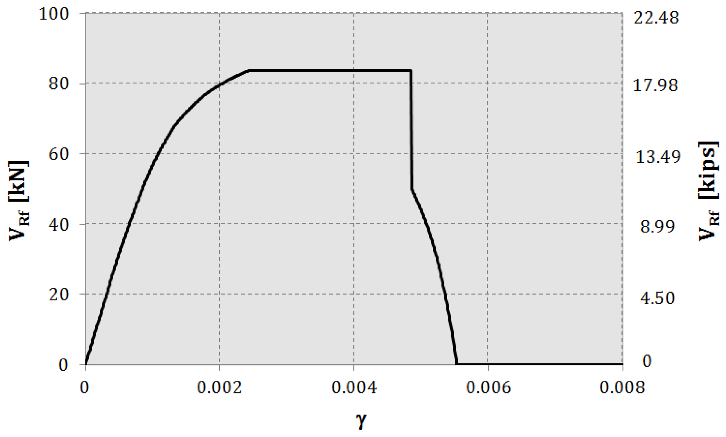
It is worth noticing that when considering a single FRP sheet crossing the crack, which is the case analyzed herein,
actually corresponds to
, where
is the length of the crack (see
Figure 1) and is a constant value when a certain geometrical configuration of the beam and θ are assigned. This condition explains why, in
Figure 4, we see just one curve representing
VRf, expressed as a function of γ.
Figure 4.
Contribution of FRP to the shear capacity on varying of the crack opening γ. Parameters: H = 400 mm; θ = 30°; Ef = 390 GPa; tf = 0.254 mm; t = 1; Rck = 30 MPa.
Figure 4.
Contribution of FRP to the shear capacity on varying of the crack opening γ. Parameters: H = 400 mm; θ = 30°; Ef = 390 GPa; tf = 0.254 mm; t = 1; Rck = 30 MPa.
5. Contribution of Stirrups to Shear Capacity
The overall contribution of the stirrups to the shear capacity can be calculated as the sum of the contributions of each single stirrup, based on its effective strain as it is crossed by the crack, as a function of both the crack opening γ and the position
x along the crack; see
Figure 3. Therefore, the contribution of all of the stirrups to the shear capacity can be expressed as:
where
is the shear strength of one of the
stirrups. Therefore, Equation (3) can also be expressed as:
where
is the cross-sectional area of one stirrup,
is the number of legs of the single stirrup and
is the bar diameter;
is the spacing of stirrups;
is the tensile stress in each stirrup that is expressed as a function of the strain
, given as:
Where all of the symbols have the meaning explained above and
La is the “bonding length” of the stirrups. Notice that the numerator of Equation (5) represents the crack width; see the compatibility condition in Equation (1).
Notice that, since the crack width changes along the
x-axis by following an assumed linear law, also the strain of each stirrup varies linearly along the longitudinal axis of the crack.
Figure 5 shows how strains and stresses of the stirrups change as a function of γ for the case of four stirrups crossing the crack. For example, when
(see the dotted lines), the first stirrup has zero strain and stress, because it is placed at the crack tip (see
Figure 3); the second one is in the linear field and contributes to the shear capacity proportionally to its stress (see Equation (4)); the third and fourth, which are the farthest from the crack tip, give their maximum contribution to the shear capacity, since they are both yielded.
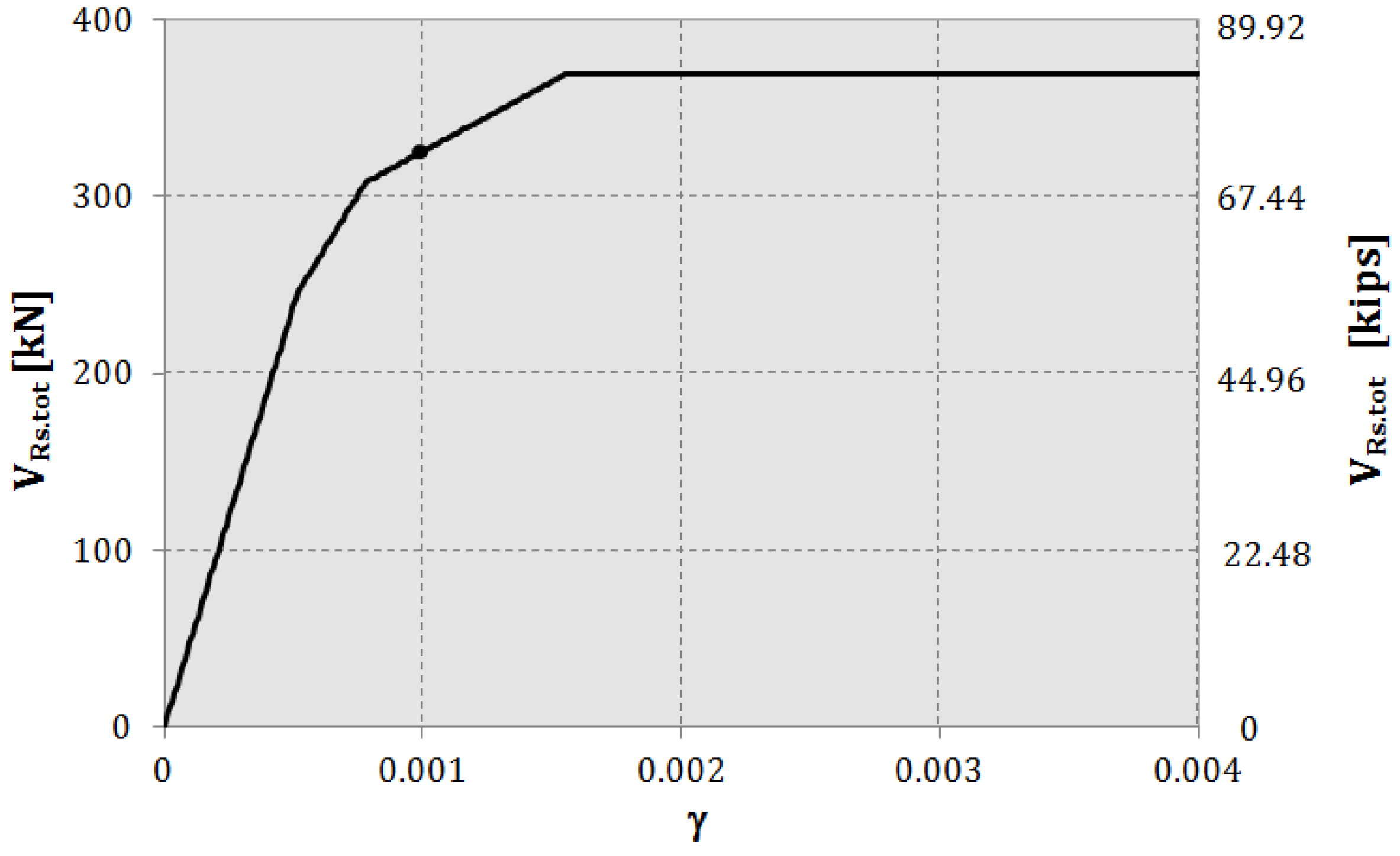
Then, the overall contribution of the stirrups to the shear capacity on the varying of γ is shown in
Figure 6, demonstrating that, for the set of variables chosen for this analysis, not all of the stirrups contribute to the shear capacity with their maximum strength: this confirms that the common assumption of assuming all of the stirrups as yielded can lead to an unsafe overestimation of the overall shear capacity.
Figure 5.
Strain and stress of each stirrup as a function of the crack opening γ. Parameters: H = 400 mm; θ = 30°; ss = 100 mm; fyk = 355 MPa; Es = 210 GPa.
Figure 5.
Strain and stress of each stirrup as a function of the crack opening γ. Parameters: H = 400 mm; θ = 30°; ss = 100 mm; fyk = 355 MPa; Es = 210 GPa.
Figure 6.
Overall contribution of stirrups to the shear capacity on varying of γ. Parameters: H = 400 mm; θ = 30°; ss = 100 mm; fyk = 355 MPa; Es = 210 GPa.
Figure 6.
Overall contribution of stirrups to the shear capacity on varying of γ. Parameters: H = 400 mm; θ = 30°; ss = 100 mm; fyk = 355 MPa; Es = 210 GPa.
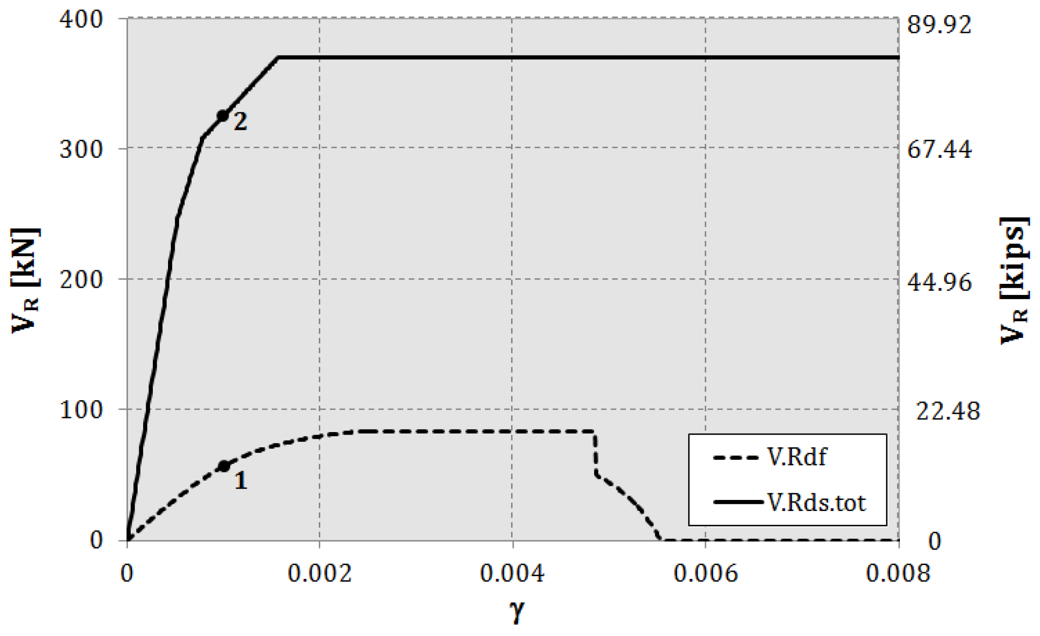
The compatibility condition imposed along the crack allows evaluating the “effective contribution” of FRP sheets/strips and stirrups to the shear capacity on varying of γ, as shown in the following
Figure 7.
Figure 7.
Variation of VRs.tot(γ, x) and VRd.f(γ) on varying of γ. Parameters: H = 400 mm; θ = 30°; ss = 100 mm; fyk = 355 MPa; Es = 210 GPa; Ef = 390 GPa; tf = 0.254 mm; t = 1; Rck = 30 MPa.
Figure 7.
Variation of VRs.tot(γ, x) and VRd.f(γ) on varying of γ. Parameters: H = 400 mm; θ = 30°; ss = 100 mm; fyk = 355 MPa; Es = 210 GPa; Ef = 390 GPa; tf = 0.254 mm; t = 1; Rck = 30 MPa.
6. Equilibrium Condition: Concrete Strut Crushing
Figure 2 shows the proposed simplified mechanical model where:
is the axial tensile force acting in all of the stirrups;
is the axial force in the FRP sheet; and
is the corresponding axial force in the concrete strut.
The equilibrium of the resultant forces of the simplified model (see
Figure 2) reads:
where
is the vertical projection of the axial force acting on the concrete strut. Therefore, in order for equilibrium to be satisfied, the following condition has to be met:
where
is the vertical component of the strut compression strength. Equation (7) can be made explicit as follows:
where θ and
have the meaning explained above and
represents the length of the representative span of the shear resisting model; see
Figure 1. Notice that
is the reduced compressive strength of concrete, according to Regan [
14], which approximately accounts for the biaxial stress state in concrete, by reducing its compressive strength.
Equation (8) can be further simplified into:
which represents the verification of a concrete section subjected to the axial force
.
7. Parametric Study
For the purpose of validating the model here proposed, a parametric study has been conducted: the variation of the steel stirrup and FRP sheets/strip contribution to the shear capacity at varying of the crack opening γ has been analyzed for different values of the following parameters:
is the depth of the cross-section;
is the crack slope to the beam longitudinal axis;
is the stirrup spacing;
is the Young’s modulus of FRP sheets/strips;
is the thickness of the single FRP sheet/strip;
is the concrete compressive strength.
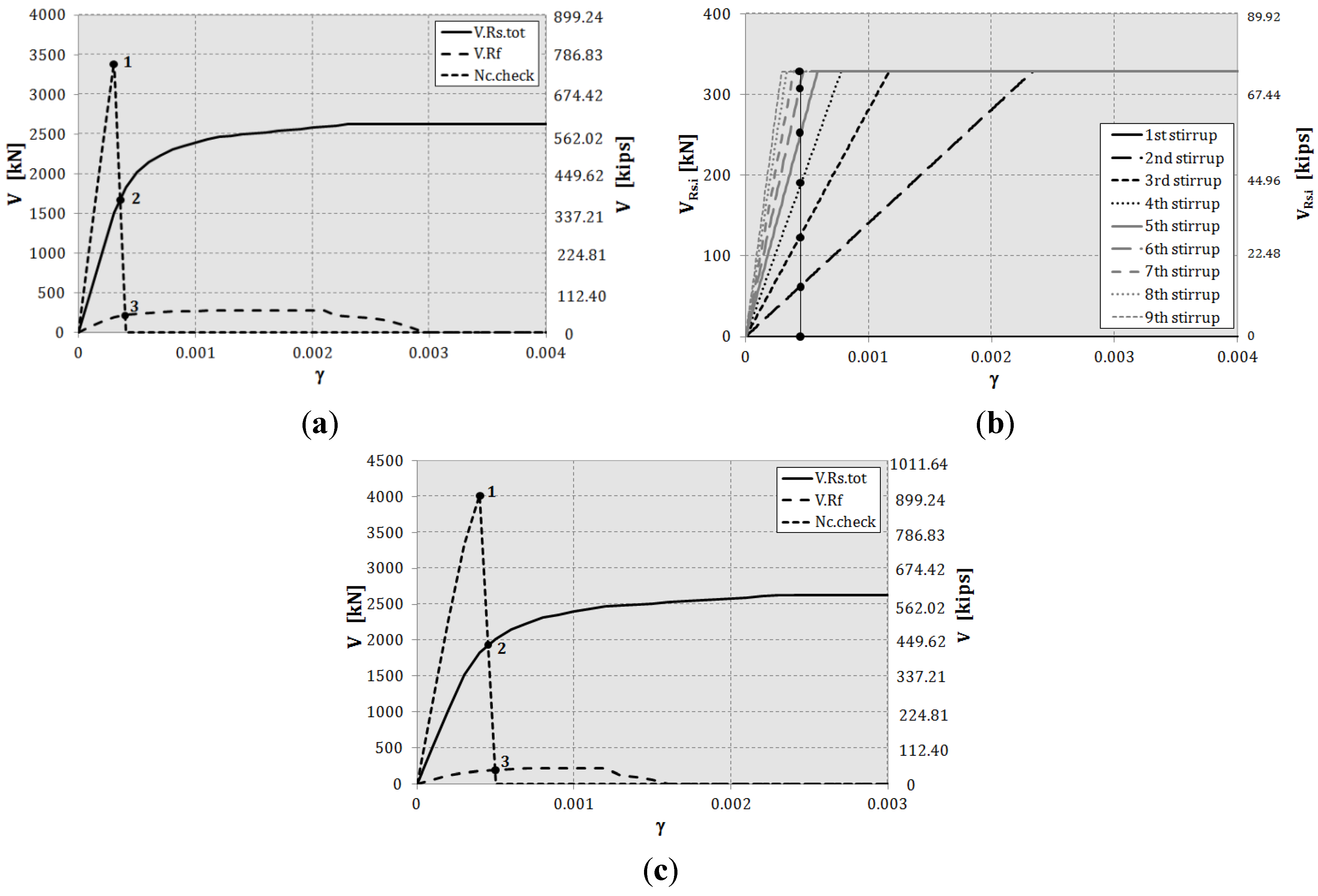
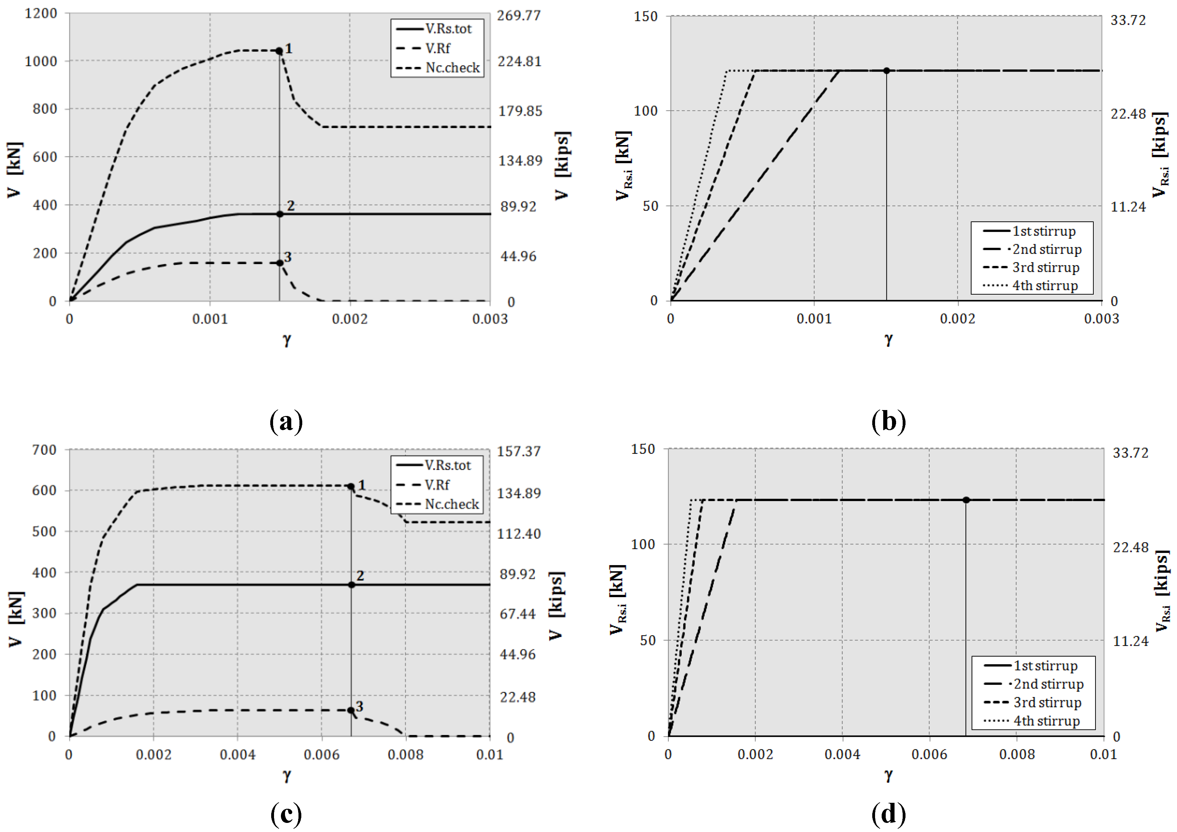
Among all of the results obtained from the combination of the parameters above, three cases are analyzed in detail thereafter and shown in
Figure 8,
Figure 9 and
Figure 10: in Plots (a) and (c), long-dotted and solid curves trace the contribution of FRP sheet,
, and steel stirrups,
, to the shear capacity, respectively, and short-dotted lines the variation of the compressive axial force in the concrete strut,
. Therefore, by drawing a vertical line at any value of the crack opening γ, it is possible to check the failure sequence of the shear resisting elements and the corresponding actual contribution of each of them to the current shear capacity. Plots (b) and (d) also show how many stirrups are intercepted by the crack and how much each of them contributes to the shear capacity at varying of the crack opening γ.
Figure 8a–c shows the case of pseudo-ductile shear behavior, wrongly taken for granted in current design and assessment procedures, meaning that the yielding of stirrups precedes the FRP debonding, and the concrete strut does not crush.
The parameters considered for Cases (a) and (c) are in the following
Table 1.
Table 1.
Pseudo-ductile shear behavior: parameters.
Table 1.
Pseudo-ductile shear behavior: parameters.
| Case | H (mm) | θ (degrees) | s (mm) | Ef (GPa) | Es (GPa) | tf (mm) | t | Rck (MPa) | fyk (MPa) | αs (degrees) | ϕs (mm) |
|---|
| (a) | 450 | 30 | 200 | 390 | 210 | 0.44 | 1 | 20 | 335 | 90 | 8 |
| (c) | 400 | 45 | 100 | 200 | 0.254 | 30 |
Referring to (a), the graph shows that at
, the FRP sheet debonds, when all of the stirrups, three in this case, not considering that at the crack tip, see (b), are yielded and the concrete strut is not crushed. Therefore, in this case, along with the one shown in (c) and (d), FRP and stirrups give their maximum contribution to the shear capacity.
Figure 8.
Pseudo-ductile shear behavior: (a,c) the contribution of FRP and stirrups to the shear capacity at varying of γ; (b,d) the actual contribution of each stirrup at varying of γ.
Figure 8.
Pseudo-ductile shear behavior: (a,c) the contribution of FRP and stirrups to the shear capacity at varying of γ; (b,d) the actual contribution of each stirrup at varying of γ.
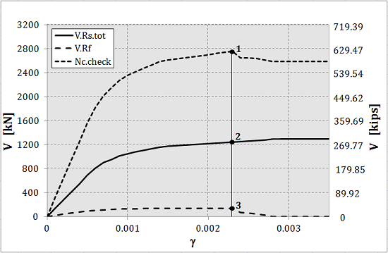
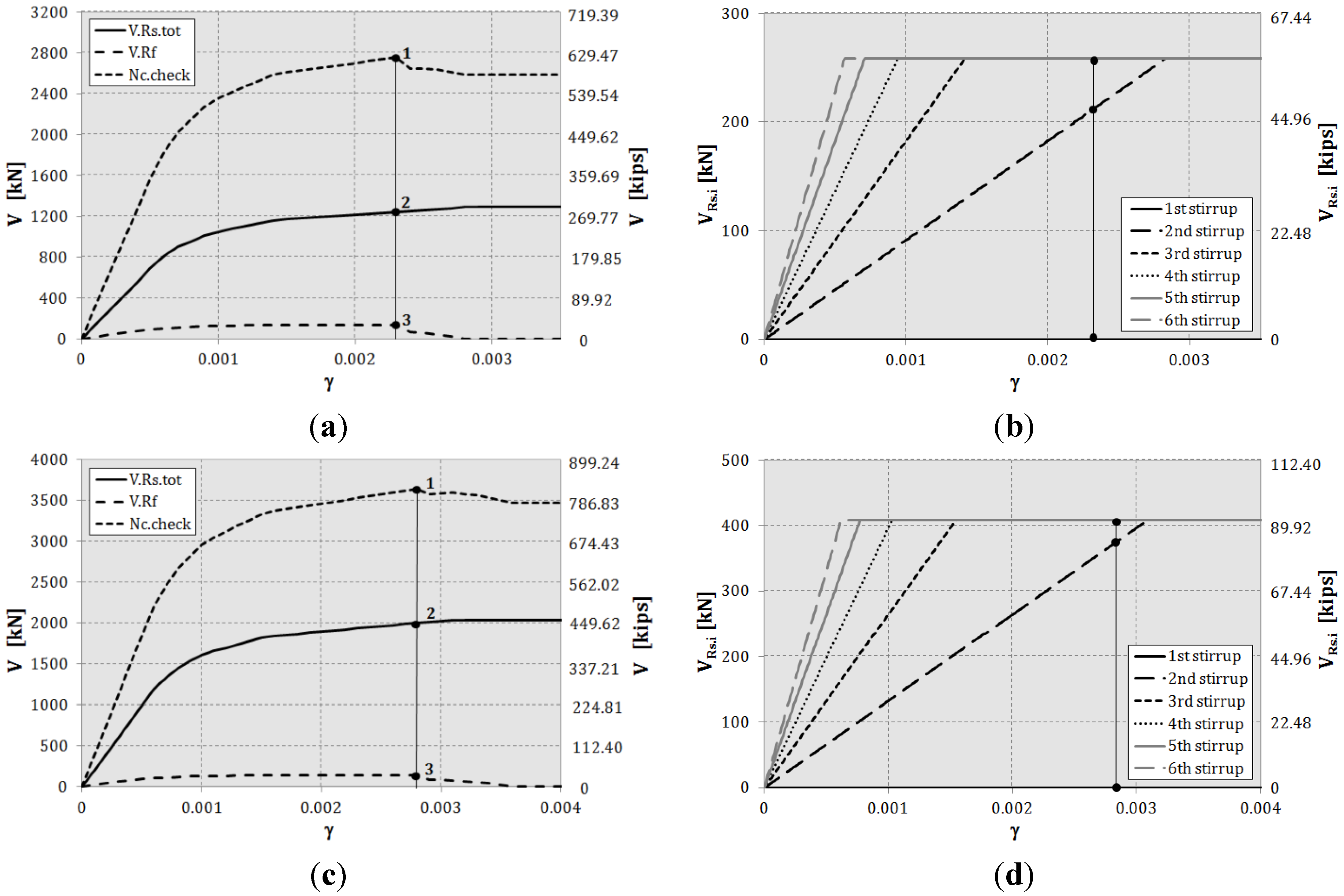
Figure 9a–c demonstrates that for some combinations of parameters (see
Table 2), the concrete strut crushes before the FRP sheet debonds and the stirrups yield: in fact, referring to (a), at
, the short-dotted curve representing the axial force acting in the concrete drops to zero, meaning that the concrete crushes. At this point, the FRP sheet has not yet reached the maximum resisting value, and among the eight stirrups intercepted by the crack (see (b)), three are yielded and five are still elastic, contributing to the shear capacity proportionally to their real stress; see Equation (4).
Figure 10a–c and
Table 3 refer to the case of an FRP sheet that debonds before all of the stirrups yielded: with reference to (a), at
, the FRP sheet reaches its maximum capacity, four stirrups are yielded and one stirrup, which is closest to the crack tip, is still elastic; see (b) and
Figure 3.
Table 2.
Crushing of concrete: parameters.
Table 2.
Crushing of concrete: parameters.
| Case | H (mm) | θ (degrees) | s (mm) | Ef (GPa) | Es (GPa) | tf (mm) | t | Rck (MPa) | fyk (MPa) | αs (degrees) | ϕs (mm) |
|---|
| (a) | 600 | 30 | 100 | 390 | 210 | 0.44 | 1 | 18 | 335 | 90 | 8 |
| (c) | 0.254 | 0.5 |
Figure 9.
Crushing of concrete: (a,c) the contribution of FRP and stirrups to the shear capacity at varying of γ; (b) the actual contribution of each stirrup at varying of γ.
Figure 9.
Crushing of concrete: (a,c) the contribution of FRP and stirrups to the shear capacity at varying of γ; (b) the actual contribution of each stirrup at varying of γ.
Table 3.
Debonding of FRP sheet.
Table 3.
Debonding of FRP sheet.
| Case | H (mm) | θ (degrees) | s (mm) | Ef (GPa) | Es (GPa) | tf (mm) | t | Rck (MPa) | fyk (MPa) | αs (degrees) | ϕs (mm) |
|---|
| (a) | 400 | 30 | 100 | 390 | 210 | 0.254 | 1 | 30 | 430 | 90 | 8 |
| (c) | 500 | 36 | 10 |
Figure 10.
FRP debonding: (a,c) the contribution of FRP and stirrups to the shear capacity at varying of γ; (b,d) the actual contribution of each stirrup at varying of γ.
Figure 10.
FRP debonding: (a,c) the contribution of FRP and stirrups to the shear capacity at varying of γ; (b,d) the actual contribution of each stirrup at varying of γ.
These last two cases demonstrate that the common accepted rule of assuming the shear capacity of FRP-RC beams in shear as the sum of the maximum contribution of both FRP and stirrups can lead to an unsafe overestimation of the actual shear capacity.
8. Validation of the Model against Experimental Results
For the purpose of validating the capability of the proposed model to estimate the shear strength of FRP-RC members, a comparison between experimental results and model predictions has been carried out.
Very few tests have been found in the literature to be taken as a reliable benchmark to validate the model, since most of those available do not report all of the information required to check the model.
As for the comparative study shown hereafter, experimental data have been gathered from an experimental campaign conducted by Grande
et al. [
15], referring only to those reporting all of the measurements necessary to verify the model.
Table 4 summarizes the geometry and materials of the three considered RC beams, strengthened in shear with FRP sheets and subjected to a three-point flexural test: basically, the specimens differ from each other for the stirrups spacing,
s, and the inclination of the main crack at the end of the test, θ.
Table 4.
Specimens: geometry and materials.
Table 4.
Specimens: geometry and materials.
| Sample | H (mm) | bw (mm) | θ (degrees) | s (mm) | Ef (GPa) | Es (GPa) | tf (mm) | t | Rck (MPa) | fyk (MPa) | αs (degrees) | ϕs (mm) |
|---|
| 1 | 450 | 250 | 30 | 200 | 392 | 210 | 0.191 | 1 | 25 | 650 | 90 | 8 |
| 2 | 20 | 300 |
| 3 | 24 | 400 |
In
Table 5, the comparison between the experimental results and the predictions of the model is shown in terms of the contribution of FRP sheets to the shear strength and total shear strength, both explicitly provided in the paper. The contribution of the stirrups, which is not given, has been calculated by imposing the compatibility condition along the crack, expressed by Equation (4).
The accuracy of the model has been evaluated referring to the overall shear capacity: the comparison demonstrates that the proposed model is able to predict the shear capacity of the FRP-RC beams with an error less than 10%.
Table 5.
Comparison: experimental results and model predictions.
Table 5.
Comparison: experimental results and model predictions.
| Sample | VRf (kN) | VRs.tot (kN) | Total shear force (kN) |
|---|
| Experiment | Model | Experiment | Model | Experiment | Model | Error (%) |
|---|
| 1 | 65 | 71 | – | 191 | 280 | 262 | 6 |
| 2 | 110 | 110 | 145 | 270 | 255 | 5 |
| 3 | 100 | 107 | 97 | 225 | 204 | 9 |
The three tests here considered, even though in a limited number, yield very promising results. Hopefully, with more experimental campaigns being carried out in recent years, in the future, there will be more comprehensive data available to completely validate the proposed model.
9. Conclusions
This work goes along the theoretical line traced by Monti and Liotta [
6], whereby the stress state in an FRP-shear-strengthened reinforced concrete element is accurately followed, with particular reference to the transverse steel stirrups, the strengthening FRP sheet/strips and the concrete strut, by progressively widening a shear crack that crosses them. This allows computing at any crack width the contributions from steel and FRP, while checking that the compressed concrete is not crushed, and correctly evaluating the evolution of the shear capacity at any step. In particular, the model allows one to verify whether the steel stirrups are yielded (either all or some of them) when FRP debonds. The objective is that of verifying if the usual assumption of adding the steel and FRP contribution is a meaningful one, also in view of the fact that it helps with simplifying the design equations. What has been observed, instead, is that there are (not peculiar) situations where the steel stirrups are still elastic when the FRP debonds: in those conditions, the actual shear capacity is lower than that computed through the purely additive formulas. This demonstrates that the current design equations need to be adjusted to account for this occurrence, which is the objective of ongoing research work.


