Microfluidics-Nano-Integration for Synthesis and Sensing


Optical Microsystems Laboratory, Mechanical and Industrial Engineering Department, Concordia University, 1455 de Maisonneuve Blvd. W., Montréal, QC H3G 1M8, Canada
*
Author to whom correspondence should be addressed.
Polymers 2012, 4(2), 1278-1310; https://doi.org/10.3390/polym4021278
Submission received: 29 May 2012
/
Accepted: 13 June 2012
/
Published: 20 June 2012
(This article belongs to the Special Issue Microfluidic-Assisted Synthesis and Modification of Polymeric Materials)
Abstract
:The recent progress and achievements in the development of preparation of nano and microparticles in a microfluidic environment is reviewed. Microfluidics exploit fluid mechanics to create particles with a narrow range of sizes and offers a finely controllable route to tune the shape and composition of nanomaterials. The advantages of both continuous flow- and droplet-based synthesis of polymers and nanoparticles, in comparison with the traditional stirred flasks methods are discussed in detail by using numerous recent examples from the literature as well as from the authors’ work. The controllability of the size distribution of the particles is discussed in terms of the fabrication approach and the characteristics of the microfluidic reactors. A special attention is paid to metal-polymer nanocomposites prepared through microfluidic routes and their application in bio-sensing. Directions for future development of microfluidic synthesis of high quality nanoparticles are discussed.
1. Introduction
‘‘Most of the cards in the microfluidic deck have still not been revealed!’’ [1]
“The field of microfluidics is in early adolescence, it is a combination of unlimited promise, this is a very exciting time for the field, but we still do not know exactly what it will be when it grows up.” [2].
Engineering of nanomaterials is the primary focus of numerous research groups as nanomaterials find extensive industrial applications in the field of catalysis, electronics, high-density magnetic recording media, sensors, and nanobiotechnology. Exigencies on the quality of particles for specific applications are becoming more and more rigorous, demanding development of new approaches for their production. The convergence of microfluidics and nanoparticle synthesis has shown considerable promise, allowing the preparation of nanoparticles with a narrow size distribution or distinct morphologies, important for developing new functional materials.
Presently, nanoparticles are synthesized mainly in a bench-top batch mode, utilizing the basic experimental techniques and equipment that is, the traditional beaker or stirred flasks methods, and the methodology, practically unchanged since the last century. Nanoparticles are synthesized through chemical reactions, by bringing together two or more reactants. For example, solution-based synthesis methods, utilized widely for the preparation of noble metals, involve the reduction of the corresponding metal salt in an aqueous solution with appropriate reducing agents, generally in the presence of surfactant molecules. In the case of mixing in reaction vessels, the reaction proceeds simultaneously, the reaction environment is not homogeneous and the nucleation and growth processes cannot be separated. Due to the variability in local conditions, nanomaterials cannot be prepared in a completely controlled and reproducible manner, leading to a polydispersity in size distribution, crystal structure and properties. Therefore, the principal challenge of the solution-based methods is the synthesis of mono-disperse nanoparticles of a desired size, with a well-determined crystal structure and shape.
Alternative promising strategies for the synthesis of high-quality nanoparticles are provided by the advent of microfluidic technology that allows rapid and homogeneous mixing because of the small dimensions of the microchannels. Microfluidic reactors, the devices that allow conducting chemical reactions on a micrometer scale, provide an ideal platform for the production of nanoparticles [3,4]. Chemical synthesis in a micro-reactor is a novel way of conducting chemistry and offers advantages in term of continuous flow, smaller amount of solvents, faster and complete mixing in very short time, compared to classical reactors. In addition, the residence time is short, leading to minimal waste and an overall better control over the reaction.
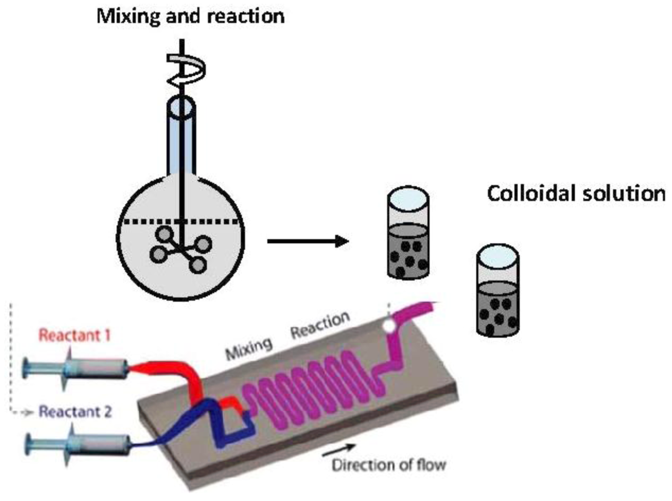
A general schematic of the traditional “flask method” and microfluidic synthesis is shown in Figure 1.
Miniaturization of the reaction platforms provides new opportunities for advanced synthesis, and opens the way for a broad range of novel applications. In micro-reactors, because of the large surface area to volume ratios within the micro-channels (2–3 orders of magnitude larger than in a batch reactor that provides broad temperature profiles), both heat and mass transport are considerably accelerated in comparison with the conventional macro synthesis equipment. In a microchannel, it takes only seconds to raise the temperature of a solution from room temperature to hundreds of degree. This results in a more uniform heating and mixing within the micro liter reactant volume, and thus, a uniform size distribution of the synthesized nanoparticles. A high surface-to-volume ratio enables the rapid dissipation of heat generated from exothermic reactions and enhances considerably the safety of conducting exothermic reactions.
The flow at the microscale is laminar and the mixing mainly occurs by diffusion at the interface between laminar layers, compared to the fast convective process determined by turbulent flow in macro systems. To prepare homogeneous nanoparticles, the nucleation should happen in a very short period of time and the materials should be added slowly, to ensure that the concentration level is lower than the critical concentration at which new nucleation will occur. Scaling down reactor dimensions to the sub-millimeter scale provides opportunities for controlling and improving the size and composition of colloidal synthesis.
Figure 1.
(a) Synthesis of nanoparticles through the traditional “flask method”; and (b) microfluidic synthesis.
Figure 1.
(a) Synthesis of nanoparticles through the traditional “flask method”; and (b) microfluidic synthesis.
Over the past decade, microfluidic devices have enabled screening of a variety of reaction conditions by varying systematically flow rates, temperature, and reactant concentrations and thus permitting both the kinetic and thermodynamic control of reactions. By understanding the fundamentals of nanoparticle formation in a microfluidic environment, it is possible to optimize the quality of the resulting products using very small amounts of reagents. The rapid and controllable mixing which allows for fast heating and cooling, combined with the manipulation of variables such as temperature, concentration gradients and pressure, showed that continuous-flow processing on the micro-scale can be used to synthesize semiconductors, noble metals, metal oxides, core-shell and polymer particles, of desired structures and specific characteristics. These merits are also important for a variety of applications in analytical chemistry, biochemistry, clinical diagnosis, medical chemistry and industrial chemistry.
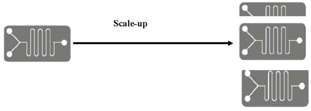
In a continuous, single-phase flow, the reagents are mixed in micro-channels under diffusion-based laminar flow reaction conditions. In microfluidic devices, fluids normally flow through channels without turbulence and, as a result, layers of fluids containing different reagents are able to flow along together and mix only by diffusion. The mixing resulting from the laminar flow is around 100 times faster when a system is 10-fold smaller [5]. Based on the flow types in microfluidic devices, two kinds of microreactors have been developed and used to carry out the synthesis of nanoparticles: continuous and micro droplets/segmented flow reactors. Continuous microreactors are preferred as, they are more productive and the scale-up is easier compared to droplet reactors [6,7]. Scale-up can be realized, either by increasing the throughput or running the reactor longer as shown in Figure 2.
Both, capillary tubes and coaxial flow microreactors made of glass or polymers have been successfully used for the synthesis of particles of a wide range of compositions and structures and an extensive range of parameters have been explored. However, problems such as adhesion to the walls and blockage of the channel are difficult to avoid because, at this small scale, the interactions with the surface are much more important than the particle motion [8]. In order to enhance mixing in continuous flow micro-reactors, channels of different shapes (Y and T) are used and, sometimes, a micro-mixer is integrated in the system as well. Micro-mixers can reduce the mixing time to milli- or even, nanoseconds [9]. However, due to non-uniform velocity profiles, there is a broad residence time distribution, leading to an equally broad particle size distribution. Mixing can be improved by introducing obstacles within the channels or grooves on the channel surfaces [10].
Figure 2.
Schematic of scale-up of microfluidic synthesis.

Instead of the continuous flow micro-reactors, in recent studies, segmented flow micro-reactors, that is, discrete droplets in a flowing immiscible carrier liquid are used as promising reaction vessels. Droplets are produced spontaneously, by injecting laminar streams of aqueous reagents into an immiscible carrier fluid, e.g., oil. Each liquid drop contains the reactants, while the carrier fluid serves only to segment the flow and induce mixing. The droplets are separated from each other and from the wall of the channel. Each droplet serves as a miniaturized reactor, enabling nanomaterial synthesis. The velocity of all the droplets along the channel is the same, thus eliminating velocity dispersion. The mixing is efficient and rapid and reagents can be transported by using chaotic mixing within droplets, by folding, stretching, and reorienting the fluid and also by using suitable channel geometries. Nanoparticles are encapsulated in the droplets and thus cannot adsorb and aggregate on the walls. Microfluidic synthesis compartmentalized within the droplets has been successfully used for the synthesis of semiconductor nanocrystals and, in a limited extent, for the synthesis of gold nanoparticles of tailored shapes.
Additional advantages provided by micro-reactors are low reagents consumption, elimination of unwanted side reactions, and the possibility of synthesizing nanomaterials as required at the point-of-use, which is important, especially in the case of transportation and storage of toxic, explosive or otherwise harmful materials. Potentially toxic, highly reactive starting materials can be safely confined in a micro-reactor and, high temperatures and pressures can be used, without developing any potentially hazardous situation. Other benefits of microfluidic technology include higher reactant conversion, less by-product generation, and the possibility of reagent recycling.
The miniaturization of synthesis platforms enables a broad range of biological and medical applications. The importance of micro- and nanoparticles in biomedical science stems from their size dimensions that are close to that of cells, tissues and microorganisms. Nanoparticles have applications in advanced drug delivery systems, biomolecular sensing, targeted imaging, and thin film coatings.
In the following sections, the achievements in the microfluidic synthesis of different categories of nanoparticles including inorganic, polymers, and hybrid composite materials, in a quite large range of size, from nanometers to micrometers, for a variety of applications are reviewed. The application of metal-polymer nanocomposite materials for bio-sensing is emphasized. The advantages of microfluidic synthesis of polymers and hybrid materials are stressed and new directions for future work are highlighted. Issues related to scaling up for, industrially viable processing are discussed as well. The review reflects the progress in this field during the last decade.
2. General Microfluidic Strategies
The fluid mechanics of liquids in micro-channels will not be discussed in this review. However, it has to be stressed, that there are important changes in the fluid properties, when moving from macro-scale to micro-scale. Indeed, at the micro-scale, the flow is laminar and the reagents can mix only by diffusion across the interface and the rate of the reaction is determined by the rate of mixing [5]. As shown in the previous section, microfluidic reactors can be grouped into two major categories: single phase continuous flow devices and segmented (two-phase) flow devices [11]. Droplet-based microfluidic devices are part of the segmented flow devices. Capillary tubes, the simplest continuous flow microfluidic devices, are included as well. In this section, the general microfluidic strategies and their general principles are described briefly. Examples for the utilisation of microfluidics for a range of applications will be presented in the section on the microfluidic synthesis.
2.1. Continuous Flow Synthesis
Continuous flow synthesis, based on the manipulation of continuous liquid flows through micro- fabricated channels is by far the most used strategy in microfluidics because its high level of controllability. Actuation of the liquid flow is realized, either by external pressure sources, external mechanical pumps, integrated mechanical micro-pumps, or by combinations of capillary forces and electro-kinetic mechanisms. Syringe pumps provide a quick and simple method for pumping fluids through micro-channels. Continuous-flow microfluidic operation is easy to implement and it is adequate for many applications, and for certain additional post-synthesis operations. However, it is less suitable when a high degree of flexibility in the fluid manipulations is required. The closed-channel systems are inherently difficult to integrate and scale because the parameters that govern the flow field vary along the flow path, making the fluid flow at one location dependent on the properties of the entire system. Permanently etched micro-structures also lead to limited possibilities to reconfigure the system. In addition, substantial volumes of reagents and relatively long channels have to be used [12]. In continuous-flow systems, highly sensitive microfluidic flow sensors, based on MEMS technology, are used for monitoring the flow.
The simplest micro-reactors used by Mulvaney et al. and Maeda et al. for the synthesis of semiconductor nanoparticles were capillary-tube reactors [13,14].
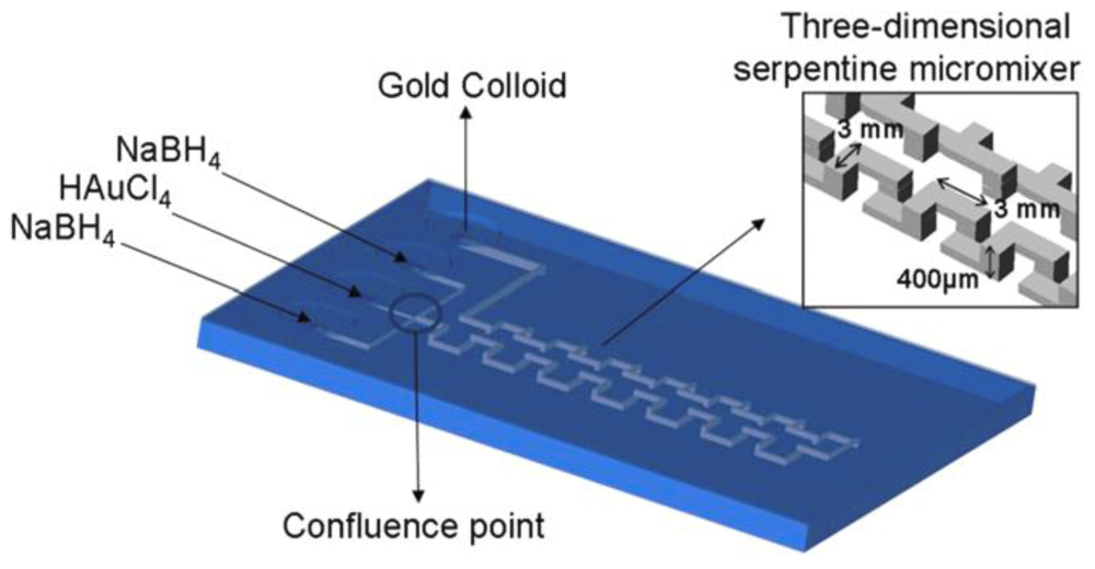
A water or oil bath is used to control the temperature, and, because the small dimensions of the channel, very short times are necessary to heat a liquid from room temperature to 300 °C [13]. Different materials such as glass, polymers and stainless steel can be used to fabricate the capillary tubes. For the fabrication of composite materials such as CdSe/ZnS, two-step reactors are used. It was observed that sometimes, because of the poor mixing of reagents in the short linear channels, unstable nanoparticles are produced. In this case, a serpentine micromixer is used to increase the length of the channel. This setup has been used by Gomez de Pedro et al. for the synthesis of gold nanoparticles in a ceramic microfluidic device by using a low-temperature co-fired ceramics technology (LTCC) (Figure 3).
Figure 3.
Microfluidic low-temperature co-fired ceramics (LTCC) platform design for the synthesis of gold nanoparticles consisting of the concept of hydraulic focusing and a three-dimensional serpentine micromixer for the reagent mixture [15].
Figure 3.
Microfluidic low-temperature co-fired ceramics (LTCC) platform design for the synthesis of gold nanoparticles consisting of the concept of hydraulic focusing and a three-dimensional serpentine micromixer for the reagent mixture [15].

This microreactor takes advantage of the substrate material (ceramic tapes) and its associated microfabrication technology. By using ceramic tapes, multilayers can be fabricated easily and, hence, fluidic components can be integrated in a single device. In this work, gold nanoparticles are obtained by a simple one-phase reaction in which the gold ions are reduced by sodium borohydride.
2.2. Discrete Microfluidic Systems
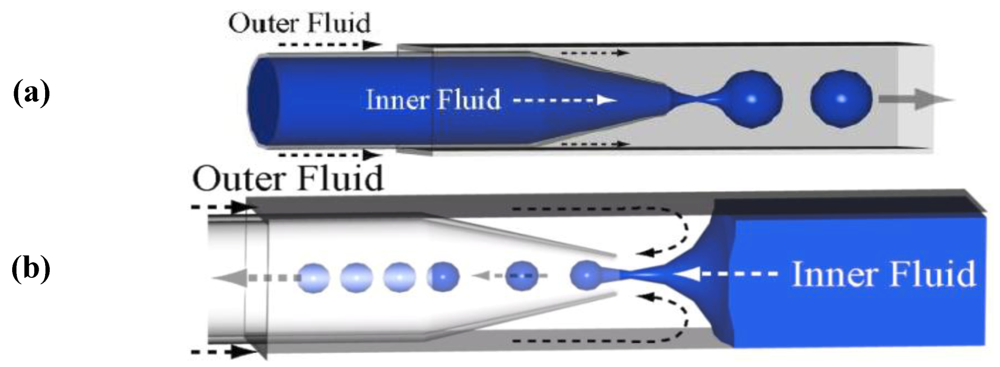
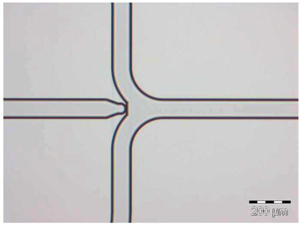
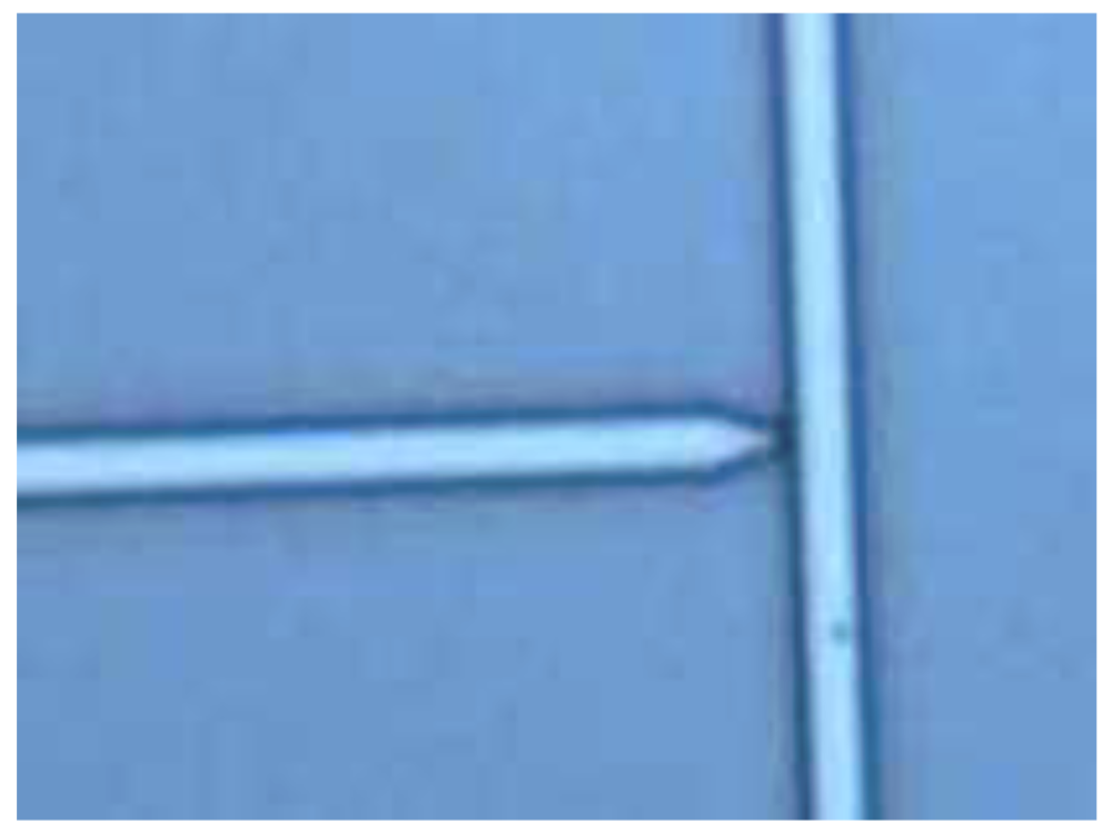
Droplet-based microfluidic systems called also segmented flow or multiphase microfluidic flow, is an emerging area of microfluidic research which has been widely used in nanoparticle synthesis. In order to induce the flow instability necessary for forming the droplets, multiple laminar streams of aqueous reagents are injected into an immiscible carrier fluid. There are several distinctive advantages in droplet-based microfluidic systems. First, the systems promise a new high-throughput technology that enables the generation of thousands of discrete micro-droplets per second. The reagents are confined inside the mono-dispersed droplets or plugs in water-in-oil (w/o) emulsions and the transport occurs with no dispersion. Furthermore, due to the short diffusion distance and chaotic mixing within droplets, fast mixing can occur within minute volumes of micro-droplets of nano-liter to femto-liter range by stretching, folding, and reorienting the fluid. The variation of the channel dimensions can regulate the droplet volumes and decrease volumes considerably, compared to the assays in conventional micro-titer plates. It is the convergence of these features and the ability to manipulate the droplet motions that provides a good approach to synthesis [16]. A flow-focusing microcapillary device showing the formation of droplets can be seen in Figure 4.
Figure 4a illustrates the co-flow geometry—a three dimensional co-axial flow, in which one fluid is flowing inside the circular capillary and the second one flows through the square capillary in the same direction.
In devices using the flow-focusing geometry (Figure 4b), the two fluids are introduced from the two ends of the same square capillary, from opposite directions. The inner fluid is hydrodynamically focused by the outer fluid through the narrow orifice of the tapered round capillary [17].
Figure 5 shows the formation of hexadecane droplets with a diameter of approximately 40 μm and a volume of 25 pL. The size of the droplet can be increased or reduced by changing the flow rate of the two phases.
Figure 4.
Formation of droplets (a) co-flow geometry and (b) Flow-focusing microcapillary device for making droplets [17].
Figure 4.
Formation of droplets (a) co-flow geometry and (b) Flow-focusing microcapillary device for making droplets [17].

Figure 5.
Focused-Flow Droplet Generator chip [18].
Figure 5.
Focused-Flow Droplet Generator chip [18].
When the channels are coated with a hydrophobic material, water droplets can be kept inside an organic phase. Figure 6 shows a T-shaped droplet generator chip fabricated by Micronit Microfluidics.
Figure 6.
T-Shaped Droplet Generator chip [18].
Figure 6.
T-Shaped Droplet Generator chip [18].
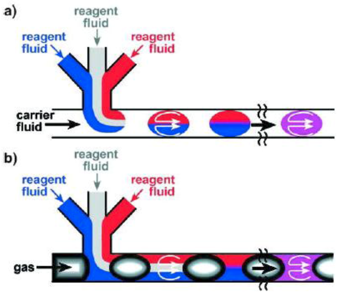
Ismagilov et al. have categorized the segmented flows according to the phase where the reaction takes place [19].
In the first type, the carrier fluid encapsulates the droplets in which the reactions occur and the reagents are separated from the walls (Figure 7a). In the second type of segmented flow, droplets are separated by discrete gas bubbles and the reaction occurs in the continuous phase (Figure 7b).
Figure 7.
Segmented flows in microfluidic channels. (a) Discrete liquid plugs are encapsulated by an immiscible continuous phase (carrier fluid) and, due to the surface properties of the micro-channel walls, they are preferentially wet by the continuous phase; (b) Aqueous slugs are separated by another immiscible phase and reactions occur within the continuous phase [19].

3. Microfluidic Synthesis
3.1. Synthesis of Inorganic Nanoparticles
In this section, the microfluidic synthesis of metal and semiconductor nanoparticles as well as other colloidal materials will be briefly reviewed. When possible, the micro-scale synthesis will be compared to the conventional methods used for the same material. This section is not extensive. Several representative syntheses will be discussed for each material.
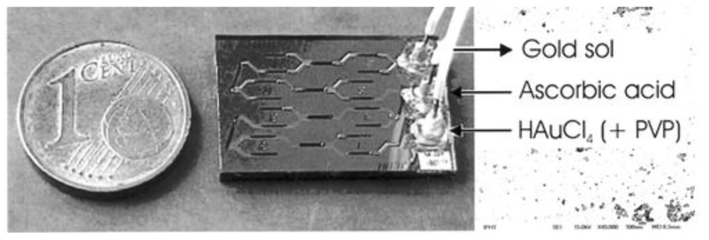
The most important advantage of the microfluidic devices for the synthesis of metal nanoparticles is the capability of controlling the temperature along the flow. This fact, together with an efficient mixing of reagents and the possibility to add reagents in any part of the channel, contribute to the generation of homogeneous nanoparticles in a well-controlled fashion. Three examples regarding the synthesis of gold nanoparticles in continuous flow systems are presented below in a chronological order to show the progress realized for a duration of less than a decade. Wagner and Köhler have used a simple microfluidic device (as shown in Figure 8) to synthesize gold nanoparticles by using a mild reducing agent and poly(vinylpyrrolidone) as a capping agent [20].
A mild reducing agent, ascorbic acid is used in this synthesis, in the presence of poly(vinylpyrrolidone) (PVP) as capping agent, and the size distribution of the gold nanoparticles is found considerably narrower than that obtained by conventional synthesis methods. The mixing is based on split and recombination of the laminar streams. Smaller gold nanoparticles (4–7 nm) were obtained when, instead the ascorbic acid, a much stronger reducing agent such as sodium borohydride was used [21]. It seems that in this work, the size of nanoparticles was not influenced by the flow rate, or by the reagents ratios.
Figure 8.
Set-up of a microfluidic reactor used for the synthesis of gold nanoparticles [20].
Figure 8.
Set-up of a microfluidic reactor used for the synthesis of gold nanoparticles [20].

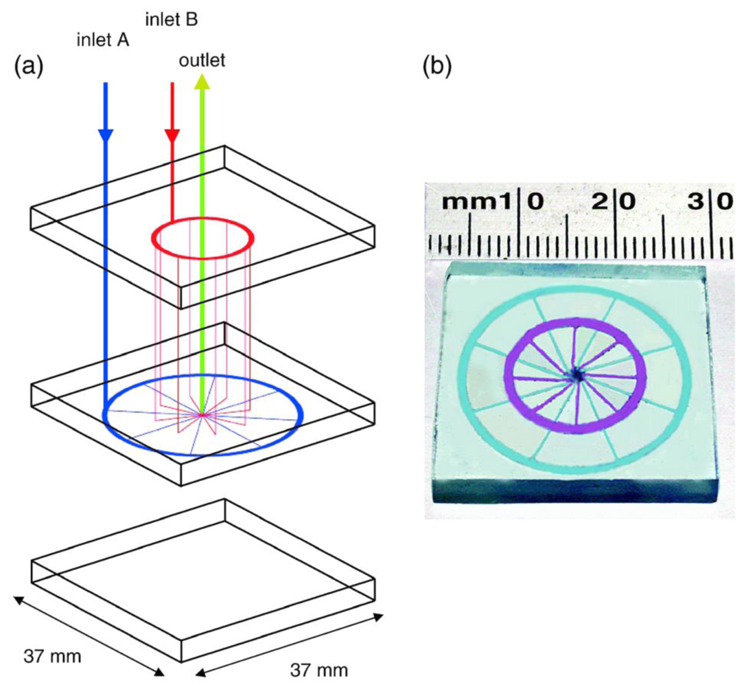
Thiol-passivated gold nanoparticles, generally called monolayer protected clusters, have been prepared for the first time, using a continuous flow microfluidic device. The authors (de Mello et al.) have shown that nanoparticles generated by the device are smaller than those prepared by the batch method and, that their size distribution is significantly narrower [22]. The schematic of the mixer is shown in Figure 9.
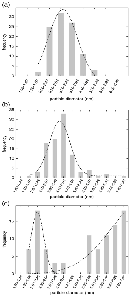
The size histogram (Figure 10) shows the narrow distribution of the thiol functionalized gold nanoparticles synthesized in the device using the mixer. The size distribution is compared to that of gold nanoparticles prepared through a bulk synthesis shown in Figure 10c.
Figure 9.
(a) Three dimensional schematic of a radial interdigitated mixer. Each mixer is fabricated in 3-layers. In the first two layers input flows are directed to two circular bus channels which, in turn, split the flow into several identical fluid laminae and deliver reagent streams towards a central mixing chamber. The final layer acts as a cap to enclose channels and as a guide for input and output capillaries. The output is from the centre of the uppermost layer; (b) Photograph of the fabricated mixer. Microchannels are filled with dye solutions to show different shadings for the different channels [22].

Figure 10.
Size histograms for particles made with a 2:1 thiol-gold ratio at (a) 800 µL min−1; (b) 400 μL min−1; (c) the comparable bulk synthesis [22].
Figure 10.
Size histograms for particles made with a 2:1 thiol-gold ratio at (a) 800 µL min−1; (b) 400 μL min−1; (c) the comparable bulk synthesis [22].

It can be seen that, while the bulk synthesis produced gold nanoparticles with non-uniform sizes, those produced in the microfluidic device provided with a mixer, show a narrow size distribution for both flow rates.
More recently, the nucleation and growth of gold nanoparticles prepared by reduction of gold ions by sodium borohydride was studied with small-angle X-ray scattering online, at a very high time resolution (100 ms) [23]. The experimental setup used for the synthesis is shown in Figure 11.
Figure 11.
Experimental setup for the synthesis of gold nanoparticles by using a static mixer coupled directly to SAXS-analysis in a flow cell [23].
Figure 11.
Experimental setup for the synthesis of gold nanoparticles by using a static mixer coupled directly to SAXS-analysis in a flow cell [23].
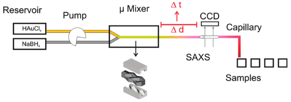
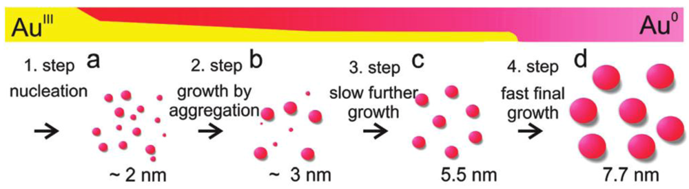
The ability to analyze online the nanoparticles is a considerable advantage. Coupling the microstructured mixer with small-angle X-ray scattering enabled online analysis of the formed nanoparticles, without requiring a synchrotron radiation facility. In general, by using this setup, the particle size is identical to sizes obtained in batch experiments. The main advantage of this setup is that kinetic information can be provided for rapid particle formation processes. In combination with XANES, the data show that initially, the gold precursor is converted into gold nuclei within less than 100 ms, followed by particle growth by coalescence as shown in Figure 12.
As in all the processes based on gold salts reduction, the final size of the particles is reached only after the precursor species are completely consumed.
Figure 12.
Mechanism of gold nanoparticles formation [23].
Figure 12.
Mechanism of gold nanoparticles formation [23].

Noble metal nanorods can be prepared from spherical metal seed crystals in a ‘growth solution’ containing the metal salt (HAuCl4) in millimolar concentrations, a mild reducing agent (ascorbic acid) and a high concentration of cetyl-trimethyl-ammonium-bromide (CTAB), which forms rod-shaped micelles as a template for the anisotropic particle growth [24]. The seed and growth solutions are injected with independent flow rates. For the preparation of silver rods, NaOH is added shortly after the mixing of seed and growth solutions. The flow is then directed through temperature-controlled tubing, allowing the crystals to grow at a fixed temperature. The extinction of the final product is measured by a flow-through spectrometer. The experimental results for gold and silver nanorod synthesis demonstrated the potential of the continuous flow setup for the synthesis of anisotropic particles as well. The continuous flow synthesis with online optical monitoring allows the reproducible and controlled synthesis of particles with specific shapes.
Thermal reduction of a few precursors of noble metals is possible by using the continuous flow approach shown in Figure 13.
Figure 13.
Synthesis of silver nanoparticles in a tubular microreactor [25].
Figure 13.
Synthesis of silver nanoparticles in a tubular microreactor [25].

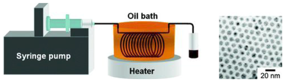
A continuous flow tubular micro-reactor is suitable for the synthesis of silver nanoparticles when a single-phase precursor such as silver pentafluoropropionate in isoamyl ether is thermally reduced at moderate temperatures. The produced silver nanoparticles have a narrow size distribution and, because of the nature of the procedure, there is no need for a mixer. Flow rates between 0.08 and 0.7 mL min−1 were tested and the TEM study showed that average diameters of silver nanoparticles prepared under these conditions were 8.6 +/− 0.9 and 8.6 +/− 1.0 nm for the molar ratios of TOA/silver pentafluoropropionate of 6 and 12, respectively.The experiments showed that low flow rates have to be used in order to obtain a narrow size distribution of silver nanoparticles. It is demonstrated that single-source precursors favour the formation of mono-disperse metal nanoparticles
Small copper nanoparticles with a narrow size distribution were produced in a microfluidic device by Kumar et al. [26], and Packirisamy et al. [27]. The most important property of microdevice-prepared copper nanoparticles is an improved stability to oxidation, very important for any application.
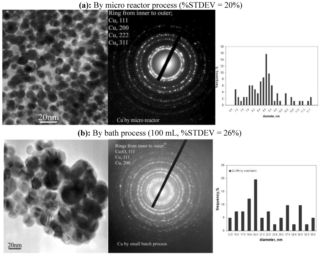
Cu nanoparticles with narrower size-distribution and a smaller size as shown in Figure 14a could be synthesized by using the sulfobetaine-Cu(I) complex as the starting material, in comparison with Cu obtained by the conventional batch process by using CuCl2. (Figure 14b) UV-Vis spectroscopy, reaction calorimetry and XANES (X-ray absorption near edge structure) investigations showed that stable and water-soluble sulfobetaine-Cu(I) complex can be formed in a THF solution by using 3-(N,N-dimethyldodecylammonia) propanesulfonate as a stabilizer during the Cu nanocolloid formation from CuCl2/THF solution. In this work, the important role of the starting material and stabilizer is emphasized.
Figure 14.
Comparison between the size distribution of copper nanoparticles obtained through the two methods: (a) microreactor process and (b) batch process [26].
Figure 14.
Comparison between the size distribution of copper nanoparticles obtained through the two methods: (a) microreactor process and (b) batch process [26].

In a recent work, copper nanoparticles have been synthesized in a microfluidic reactor and the spectra were compared to those corresponding to Cu nanoparticules prepared through the traditional batch method.
Cu2+ + BH4− + H2O → Cu0 + B(OH)3 + H2 → formation of Cu nanoparticles (1)
and their oxidation:
2Cu + ½O2 + H2O → Cu2O (2)
and
Cu2O + O2→ 2CuO (3)
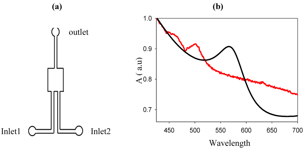
The schematic of the microfluidic reactor is shown in Figure 15. The total volume of the microreactor is approximately 20 µL3.
Copper nanoparticles were synthesized in the authors’ laboratory by using a poly(dimethylsiloxane) (PDMS) device.
Figure 15.
(a) PDMS microreactor used for the synthesis of copper nanoparticles; (b) Cu LSPR band corresponding to copper nanoparticles synthesized through the “flask method” microfluidic synthesis [27].
Figure 15.
(a) PDMS microreactor used for the synthesis of copper nanoparticles; (b) Cu LSPR band corresponding to copper nanoparticles synthesized through the “flask method” microfluidic synthesis [27].

The copper sulfate solution (2.7 × 10⁻³ M) is mixed with 4 mL of a sodium citrate solution (1%) outside the micro-reactor and then introduced into the micro-reactor, simultaneously with a sodium borohydride solution (0.02 M) through inlet 1 and 2, respectively. The spectra show the immediate formation of Cu nanoparticles. In the microfluidic environment, the Cu LSPR band is observed around 520 nm and corresponds to small (less than 5 nm) nanoparticles. In Figure 16 the spectra of Cu synthesized inside and outside the micro-reactor are compared.
Figure 16.
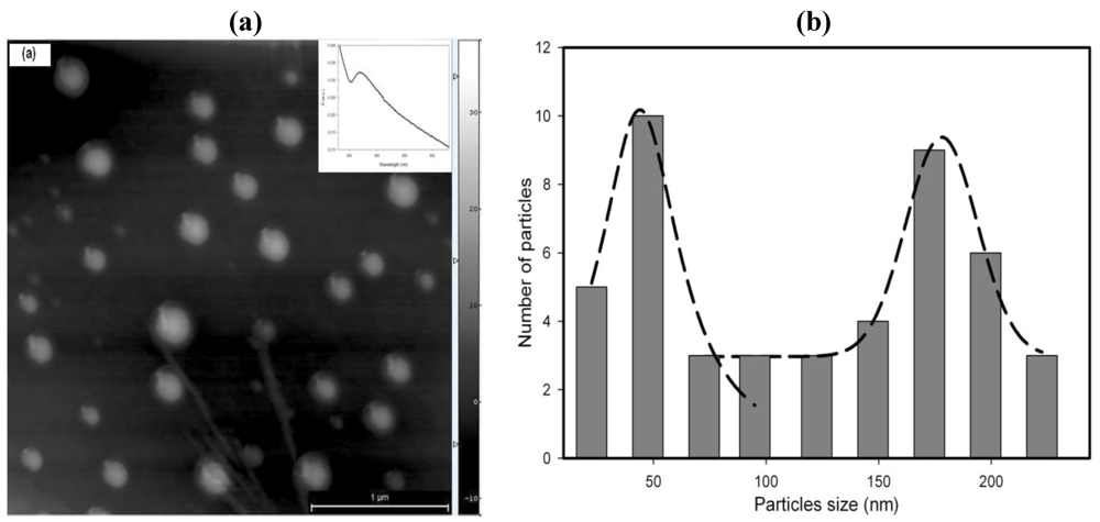
AFM image of Cu nanoparticles synthesized (a) at room temperature; (b) the corresponding size distribution. The spectrum of the stabilized Cu nanoparticles on a glass substrate is shown in the inset [28].
Figure 16.
AFM image of Cu nanoparticles synthesized (a) at room temperature; (b) the corresponding size distribution. The spectrum of the stabilized Cu nanoparticles on a glass substrate is shown in the inset [28].

Copper nanoparticles were synthesized through a “flask” process as well and their morphology is shown in Figure 16.
The AFM image shows the presence of large particles with a broad size distribution.
Because of the anaerobic conditions, Cu nanoparticles are stable in the microfluidic environment.
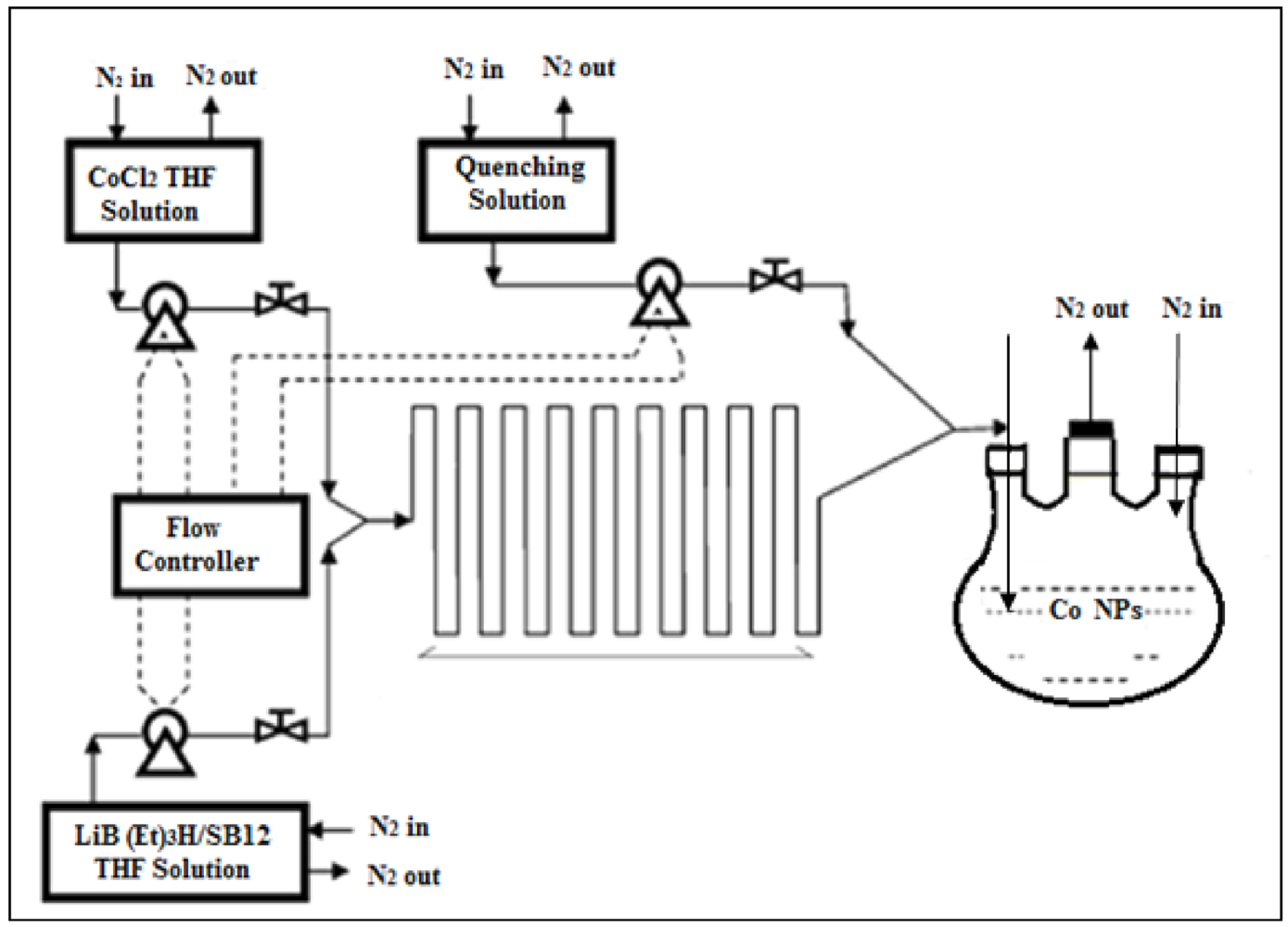
Another important application of microfluidic synthesis, the synthesis of nanoparticles with two or more crystalline phases, realized by Kumar et al. is shown in the example below (Figure 17) for cobalt nanoparticles [29].
Figure 17.
Schematic of the phase-controlled synthesis of cobalt nanoparticles [29].
Figure 17.
Schematic of the phase-controlled synthesis of cobalt nanoparticles [29].

The different crystal structures are synthesized through manipulation of parameters such as flow rates, reaction times and quenching procedures. The formation route suggested by the authors is shown below (Figure 18). They show that, by using high flow rates (high kinetic energy), the Co nanoparticles that are formed, have mainly a face-centered cubic structure, while at low flow rates, particles with hcp structures are favored. It is found that the flow rate has a marked effect only on the nucleation process as the growth of the particles, in this work, happens outside of the micro-reactor.
Semiconductor nanocrystals can also be synthesized through the continuous flow approach as shown in Figure 19.
Alivisatos et al. showed that the size of CdSe nanocrystals can be tuned by changing the parameters [30].
Figure 18.
Proposed formation route for the different phases of Co nanoparticles [29].
Figure 18.
Proposed formation route for the different phases of Co nanoparticles [29].
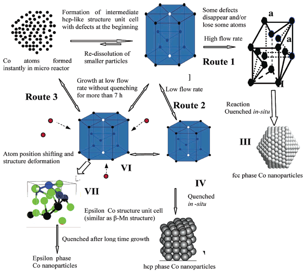
Figure 19.
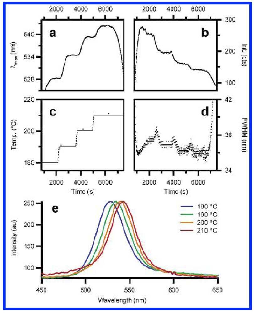
A chip-based microfluidic reactor for the synthesis of CdSe nanocrystals. Nanocrystals are sized through their continuous photoluminescence data [30].
Figure 19.
A chip-based microfluidic reactor for the synthesis of CdSe nanocrystals. Nanocrystals are sized through their continuous photoluminescence data [30].

The tuning of the size of CdSe nanocrystals is done in this work by independently changing the temperature, the flow rate through heated microchannels, and the concentration of the precursor. The microfluidic reactor employed by the author works in a continuous flow regime as shown in Figure 20. They make use of the major advantage of microfluidic reaction systems, that is, the ability to change rapidly the concentration and temperature on the scale of micrometers. The authors show that, while, similar data could have been obtained through flask synthesis, the experimental work would be very tedious.
The examples shown in this section have demonstrated the advantages of the devices based on continuous flow for the synthesis of high-quality Au, Ag, Cu, Co, nanoparticles. However, for obtaining nanoparticles with a narrow size distribution, the reactors should be integrated with mixers, pumps, and sometimes optical devices for characterizing the nanoparticles online.
The principal drawback of the continuous flow-based methods is the deposition of nanoparticles on the walls. As it has been shown in Section 2.2, an alternative approach is the use of droplet microfluidics, where the confinement within small droplets prevents the contact of the nanoparticles with the walls, and hence, their deposition.
Figure 20.
Size control of CdSe nanocrystal synthesis via flow rate and concentration (Reproduced with permission from ref. [30]).
Figure 20.
Size control of CdSe nanocrystal synthesis via flow rate and concentration (Reproduced with permission from ref. [30]).
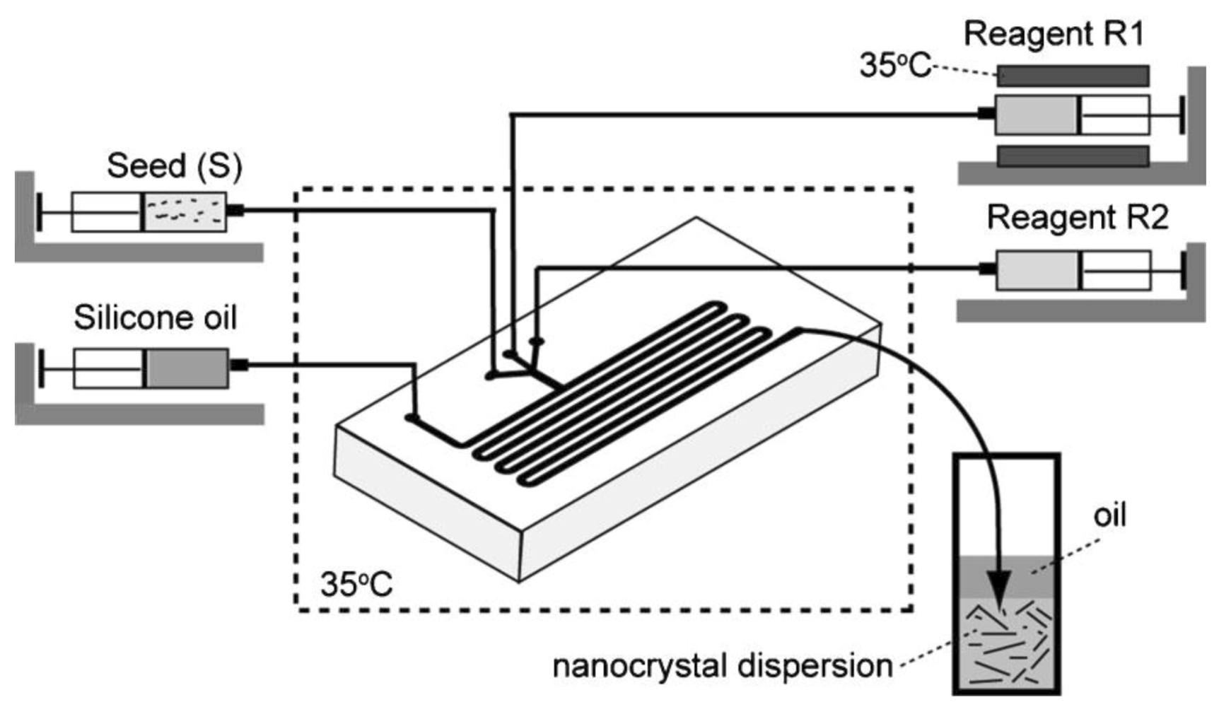
Gold nanorods of varying aspect ratios have been successfully prepared by implementing the T-junction droplet-based synthesis as shown in Figure 21 [31]. The authors adapted small-scale batch method [32] to a flow version in a microfluidic environment (Figure 19). The formation of droplets at the junction is determined by the microchannel inlet geometry, fluid viscosities, and interfacial tension, and the relative flow rates of the two immiscible fluids. Pico-liter droplets are formed containing both seeds and growth reagents and silicon oil is used as the continuous fluid. The most interesting results achieved in this study is the tunability of the shapes and thus of the UV-Visible absorption by changing parameters such as the concentration of reagents and their flow rates (Figure 22). The authors (Duraiswamy and Khan) further intend to develop an integrated synthesis method that incorporates online synthesis of gold nanoparticle seeds, and extend the residence time of growing nanocrystals on-chip, so as to enable a fully continuous process. The microfluidic synthesis proves to be quite difficult in the case of using both a seed and a growth solution.
Figure 21.
Droplet-based synthesis of gold nanorods [31].
Figure 21.
Droplet-based synthesis of gold nanorods [31].

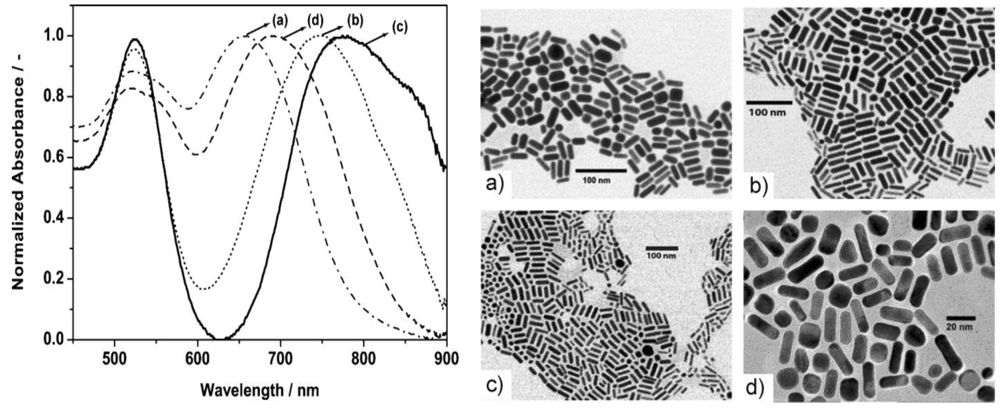
Figure 22.
UV/Vis absorbance spectra and the corresponding TEM images of rod-shaped particles of varying aspect ratios [31].
Figure 22.
UV/Vis absorbance spectra and the corresponding TEM images of rod-shaped particles of varying aspect ratios [31].

The size (aspect ratio) of the nanorods prepared through the droplet method appears to be uniform as shown in Figure 23. It can be seen that, in addition to nanorods, a number of nanospheres are formed as well. However, this is a general occurrence, hardly avoidable in both batch methods and continuous synthesis as well.
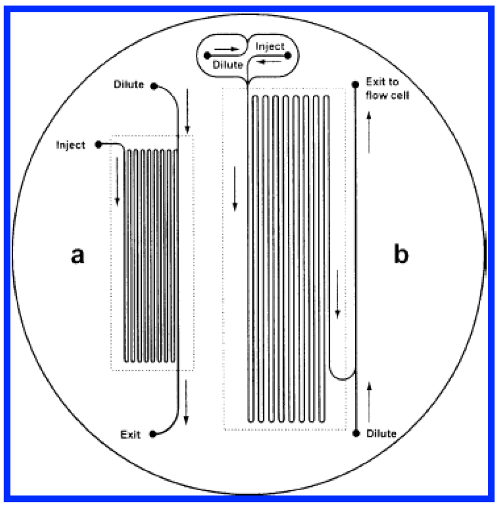
Figure 23.
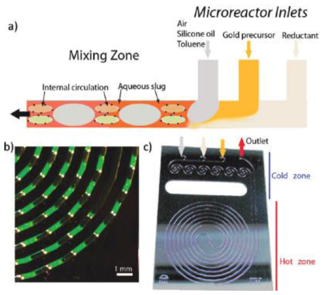
(a) Schematic of the segmented flow generation in a microfluidic reactor; (b) Detail of segmented slugs generated at a residence time of 10 s. The aqueous slug (continuous phase) contains fluorescein (green color); the disperse phase is toluene; (c) Spiral silicon/Pyrex microfluidic reactor designed for gold nanocrystal synthesis (400 μm channel width and depth, 100 μL reaction zone volume) [33].
Figure 23.
(a) Schematic of the segmented flow generation in a microfluidic reactor; (b) Detail of segmented slugs generated at a residence time of 10 s. The aqueous slug (continuous phase) contains fluorescein (green color); the disperse phase is toluene; (c) Spiral silicon/Pyrex microfluidic reactor designed for gold nanocrystal synthesis (400 μm channel width and depth, 100 μL reaction zone volume) [33].

The spectra exhibit two resonance maxima, at 520 nm that corresponds to transverse plasmon resonance (TPR) of anisotropic particles and the second peak, usually obtained between 550 nm to near-IR wavelengths (1200 nm), represents the longitudinal plasmon resonance (LPR) of anisotropic particles. The width of the band determines the polydispersity in the particles.
Because of the rapid mixing in the discrete slugs, flow segmentation has proved to generate more uniformly sized nanoparticles than the continuous flow approach [33]. By using a silicon/Pyrex microreactor (Figure 23), Jensen et al. demonstrated that the narrow size distribution of gold nanoparticles is due to the homogeneous mixing in two-phase flow systems [33].
The system studied in this work is the rapid formation of gold nuclei with sodium borohydride, a very strong reducing agent. The particle size distribution diagram for three different reaction times shows that by using short times (10 s), a very narrow size distribution can be obtained when the two phases are carefully chosen.
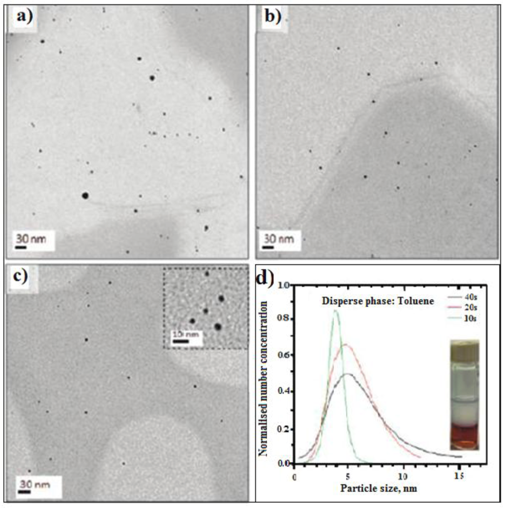
It can be seen (Figure 24d) that for a short reaction time (10 s) the particles are very small (less than 5 nm) and their size distribution is very narrow.
Figure 24.
TEM image of gold NPs synthesized in toluene-aqueous segmented flow: (a) [Au] = 1 mM; (b) Rt = 40 s; (c) Rt = 20 s; (d) Rt = 10 s. Particle size distribution diagram from AuNPs obtained in toluene-aqueous segemented flow at Rt = 40, 20, and 10 s, [Au] = 1 mM. Inset: gold NPs obtained in the toluene-aqueous phase, Rt = 10 s. Bottom: segmented slugs generated at Rt = 10 and 40 s (fluorescein was added to improve the optical resolution.

The examples shown in this section show some of the advantages of droplet-based methods. In spite of the complexity of the design and procedure, once the methodology well-established, the results in terms of size distribution are very gratifying.
3.2. Microfluidic-Assisted Synthesis of Polymeric Materials
Microfluidic synthesis of polymer particles provides the same advantages over the conventional methods as in the case of nanoparticles, that is, an improved control over their sizes, size distributions, morphologies as well as molecular weight distribution or average molecular weight of linear polymers [34]. The batch methods, especially the emulsion and suspension polymerizations, totally lack of control of size and shape of particles and, composite materials cannot be prepared directly by using these methods. The convergence of particle technologies and microfluidics has enabled a considerable progress in the field of controlled synthesis of polymeric particles, especially important for applications such as painting formulation and drug delivery. However, before describing the use of microfluidic devices for polymer particle synthesis, the linear and branched polymers synthesis is briefly reviewed in this section.
Most of the work on the microfluidic synthesis of linear polymers was done by radical polymerization or copolymerization, initiated by thermal or photoinitiators [35]. The authors (Wu et al.) demonstrated the effect of the flow rate—that is the polymerization time—on the molecular mass of the polymer.
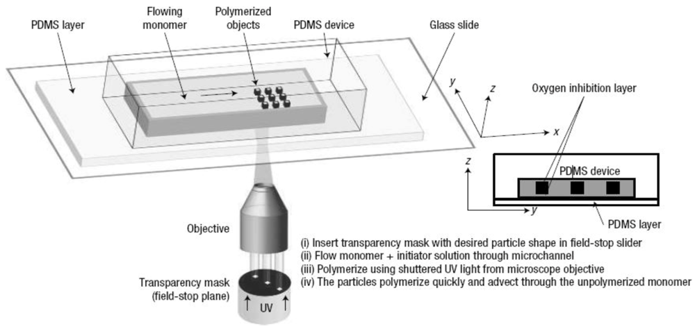
Cationic and anionic polymerization were also performed in a microfluidic format [36]. There are two different methods for producing polymer particles in microfluidic devices: single-phase (continuous flow) and multiphase (droplet) flow [4,37]. The method of continuous flow (projection photolithography technique) developed by Dendukuri et al. utilizes the objective of an optical microscope to UV irradiate through a mask, the solution flowing through the microchannel as shown in Figure 25 [38].
Figure 25.
Schematic representation of the continuous flow projection photolithography [38].
Figure 25.
Schematic representation of the continuous flow projection photolithography [38].

Through the mask, the desired particle shape can be “printed” into the monomer solution that will polymerize under the UV light, in the presence of a photo-initiator.
Monodispersed particles with diameters ranging from 20 to 1000 nm were generated by using a flow-focusing geometry by Whitesides et al. The schematic of the flow-focusing geometry used for droplet formation is described by Kumacheva et al. [39].
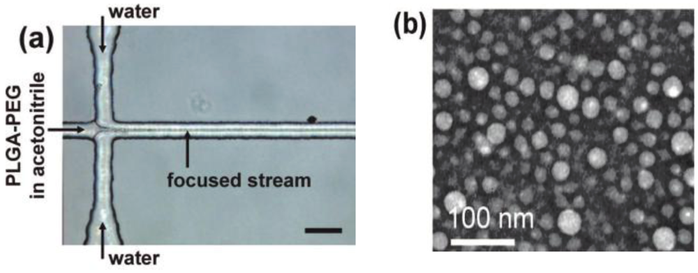
In a recent work, size-tunable polymeric nanoparticles were synthesized by Langer et al. in a novel 3D flow focusing in both the horizontal and the vertical dimensions [40,41].
PLGA-PEG nanoparticles were synthesized by hydrodynamic flow focusing in a controlled nanoprecipitation process.
The figure below (Figure 26) shows the microfluidic device as well as the TEM image of nanoparticles.
Figure 26.
Nanoprecipitation by hydrodynamic flow focusing. (a) A microfluidic device for hydrodynamic flow focusing of polymeric nanoparticles in water, Scale bar 50 μm; (b) TEM image of nanoparticles synthesized by nanoprecipitation of PLGA15K-PEG3.4K by hydrodynamic flow focusing showing spherical PLGA core-PEG corona structure of the nanoparticles [41].

The authors showed that microfluidics may be used to tune the nanoparticle size and drug loading and release.
The polymer particles synthesized within the microfluidic device shown in the figure, are composed of poly(lactide-co-glycolide)-b-polyethyleneglycol (PLGA-PEG) block copolymers, a model biomaterial for drug delivery and, because they are biodegradable and biocompatible, are suitable for controlled drug release for therapeutic applications. The authors showed that the polydispersity of the small nanoparticles (30–230 nm), made with different concentrations of polymer precursor and molecular weights, has been found very low when 3D flow focusing was used. Flow focusing enables the rapid mixing of the polymer solutions with water. Drug loading and release of the resulting nanoparticles can be precisely controlled.
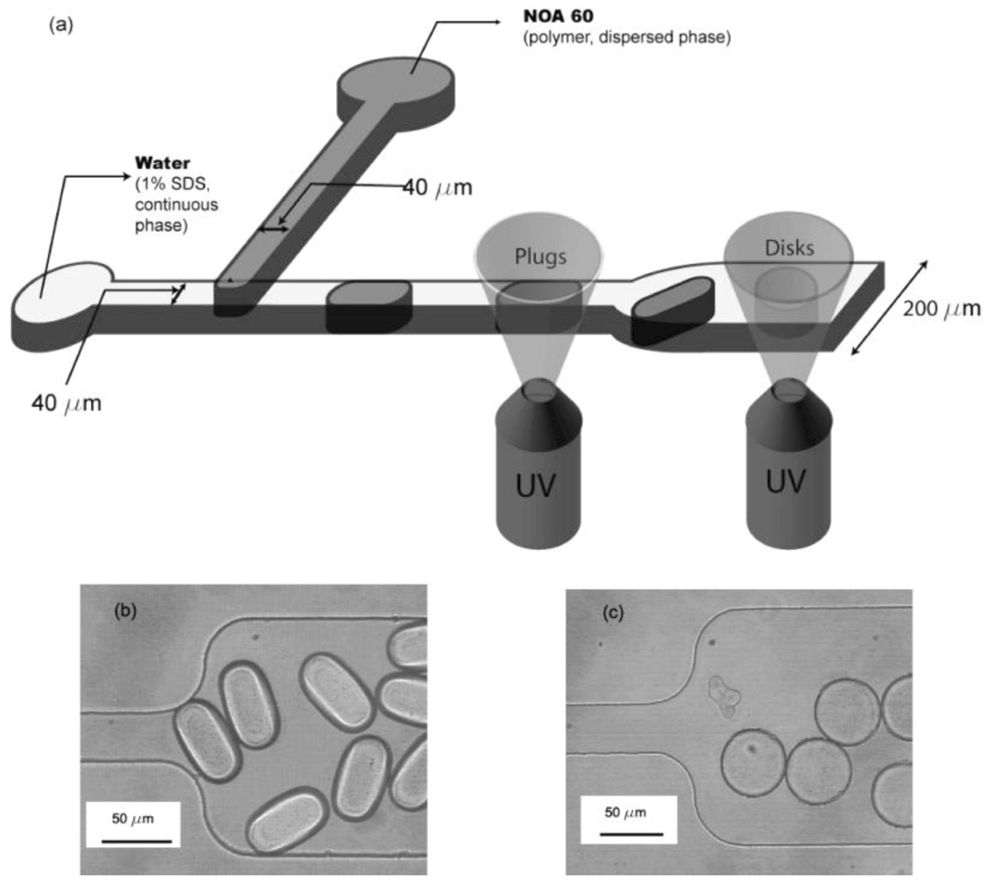
Non-spherical microparticles (plugs and disks) as shown in Figure 27, were synthesized in a microfluidic device by Dendukuri et al. [42].
By using appropriate channel geometries, curable polymer droplets formed at a T-junction, are constrained to adopt nonspherical shapes and are subsequently, irradiated with UV light to photopolymerize them and preserve the shapes. Two microchannels with different heights are used to form the droplets having the two shapes, 38 µm for the plugs and 16 µm for the disks.
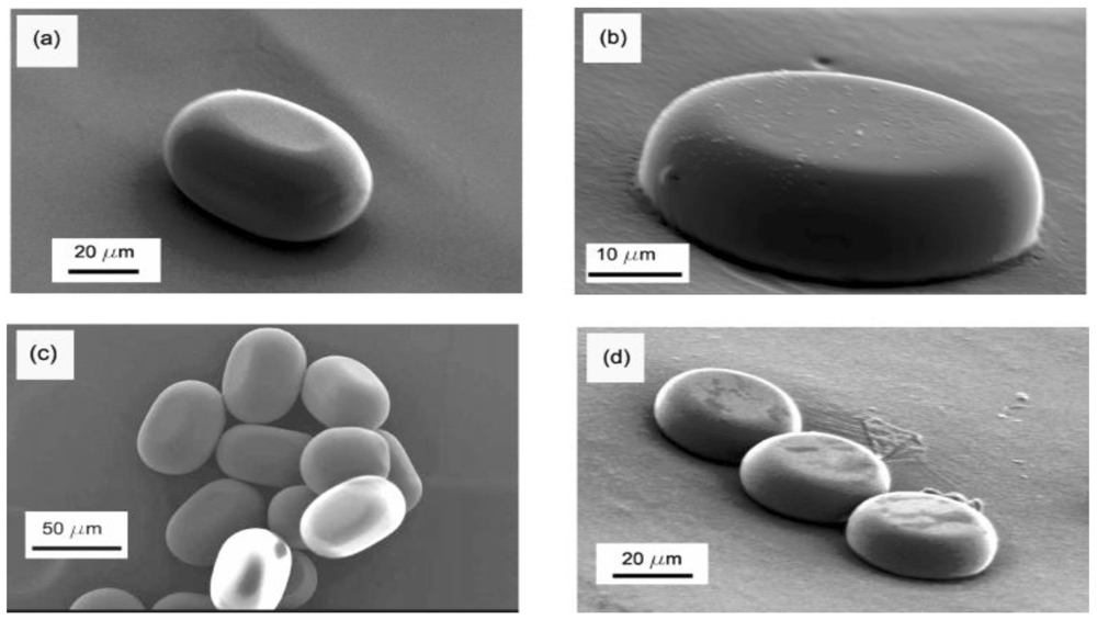
As seen in Figure 28, the non-spherical polymer particles (larger than 10 µm), fabricated through this method, are monodisperse plugs and disks. By varying the flow rates of the two phases, the dimensions of the two nonspherical microparticles can be tuned.
Figure 27.
Microchannel geometry used to create plugs and disks: (a) schematic of channel with plug and disk creation zones marked; (b) polymerized plugs in the 200 µm section of the channel, 38 µm height; (c) polymerized disks in the 200 µm section of the channel, 16 µm height [42].
Figure 27.
Microchannel geometry used to create plugs and disks: (a) schematic of channel with plug and disk creation zones marked; (b) polymerized plugs in the 200 µm section of the channel, 38 µm height; (c) polymerized disks in the 200 µm section of the channel, 16 µm height [42].

Figure 28.
SEM images of non-spherical colloids formed under varying conditions (a) plug formed at Qd = 0.05 íL/min and Ca = 1.6 × 10⁻³; (b) disk formed at Qd = 0.05 µL/min and Ca = 4.8 × 10⁻³; (c) collection of plugs formed at Qd = 0.05 µL/min and Ca = 1.6 × 10⁻³; (d) collection of disks formed at Qd = 0.05 µL/min and Ca = 9.6 × 10⁻³ [43].

3.3. Polymer Microparticles/Inorganic Nanoparticle Composite Materials (Multiscale Materials)
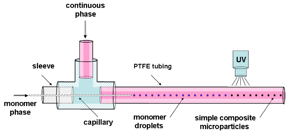
Recently, a new microfluidic route allowing the incorporation of inorganic nanoparticles in polymer microparticles was reported by Köhler et al. [43].
Simple composite microparticles have been fabricated in the capillary-based system shown in Figure 29.
Figure 29.
Schematic drawing of the capillary-based system for the production of simple composite [43].
Figure 29.
Schematic drawing of the capillary-based system for the production of simple composite [43].

In this work, Au and ZnO nanoparticles are synthesized previously in a microfluidic device and, in a second step, integrated into the polymer. The monomer phase was a mixture of an acrylate-based monomer, a photoinitiator and the gold nanoparticle (or ZnO) solution in toluene.
The droplets are hardened through thermal- or UV-induced polymerization. The polymer particles are in the size range of a few to hundreds of micrometers but the size distribution was found very narrow as shown in Figure 30.
Figure 30.
Micrographs of nano-Au/Poly(TPGDA) microparticles (A,A’) and nano-ZnO/Poly(TPGDA) microparticles (B,B’) at two different magnifications [43].
Figure 30.
Micrographs of nano-Au/Poly(TPGDA) microparticles (A,A’) and nano-ZnO/Poly(TPGDA) microparticles (B,B’) at two different magnifications [43].
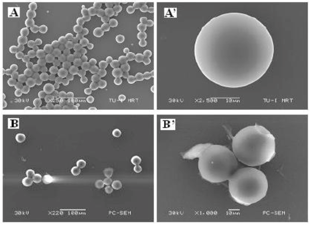
Au nanoparticles with a size around 13 nm are found to be dispersed randomly in the polymer matrix. The micrograph shows that ZnO nanoparticles are concentrated in the central part of the polymer bead.
The synthesis of composite materials demonstrated a good control over the size and size distribution.
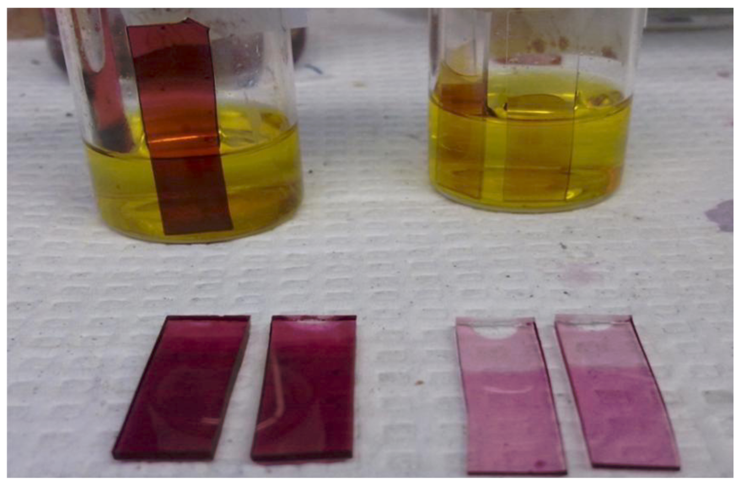
In the authors’ laboratory, gold-PDMS nanocomposite was fabricated both at the macro scale (Figure 31) and in the channel, by introducing a gold chloride solution directly in the channel of a PDMS microfluidic device as shown in Figure 32.
Figure 31.
Fabrication of Au-PDMS at the macro-scale.

Figure 32.
Fabrication of Au—PDMS nanocomposite through the reduction of Au ions inside the microfluidic channel. PDMS microfluidic device. (a) Dependence of the absorbance of Gold LSPR band on the time of reaction; and (b) SEM image of Au nanoparticles formed in the channel [44].
Figure 32.
Fabrication of Au—PDMS nanocomposite through the reduction of Au ions inside the microfluidic channel. PDMS microfluidic device. (a) Dependence of the absorbance of Gold LSPR band on the time of reaction; and (b) SEM image of Au nanoparticles formed in the channel [44].
By immersing a piece of PDMS in a gold chloride solution, the gold ions are reduced by the curing agent in the polymer and the gold nanoparticles formed by reduction are embedded in the surface layers of the polymer. The figure shows that the absorbance of the Au Localized Surface Plasmon Resonance band (LSPR) increases when the solution is left in the channel for a longer time (Figure 33).
Figure 33.
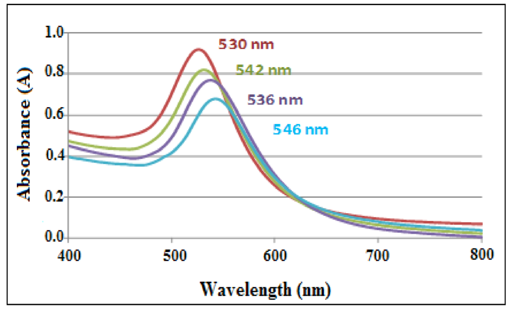
Plasmon band of Au in the nanocomposite corresponding to different stages of the immunoassay.
Figure 33.
Plasmon band of Au in the nanocomposite corresponding to different stages of the immunoassay.

Sensing experiments carried out with a Au-PDMS platform, demonstrated the sensitivity of the gold-PDMS nanocomposite to antigen-antibody interactions carried out in an immunoassay format.
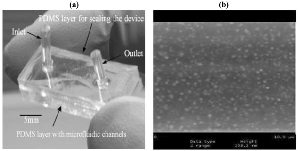
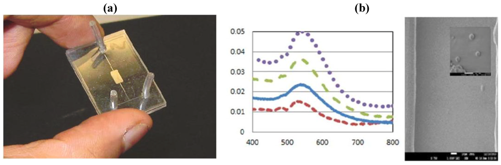
The device shown in Figure 34 was used for biosensing of a hormone polypeptide molecule by using an immunosensing format. Gold nanoparticles were functionalized by pumping a linker molecule solution through the channel and, subsequently, adsorbing the antibody and the antigen onto the immobilized gold nanoparticles. By using the shift of the AuLSPR band, the antigen can be quantified.
Figure 34.
(a) SEM image of gold nanoparticles embedded into the channel and (b) photograph of the device [45].
Figure 34.
(a) SEM image of gold nanoparticles embedded into the channel and (b) photograph of the device [45].

However, the outlook is promising; the direct use of microfluidics for biosensing is still in an incipient stage. For the time being, only the continuous flow microfluidics is used for biosensing, droplet-based methods are not yet developed for this application. For the development of analytical microfluidic chip, new functionalization methods have to be developed.
Multi-functional polycaprolactone size-controlled microcapsules entrapping an anticancer drug, together with fluorescent and supermagnetic nanoparticles, were produced by microfluidic emulsification by Chang et al. [46]. This work demonstrates a proof-of-concept approach for fabrication of multifunctional materials. The drug delivery system enabled magnetic targeting through the super paramagnetic nanoparticles, fluorescence imaging through QDs and drug controlled release properties.
Microfluidics offers new strategies for fabricating polymer particles. With traditional methods it is difficult to prepare monodisperse spherical or non-spherical polymer microparticles. To be used in commercial applications, the microfluidic production of polymer particles will have to be scaled up. In addition, efforts will have to be made to synthesize nanometer-sized polymer particles as well.
3.4. Biodegradable Microgels
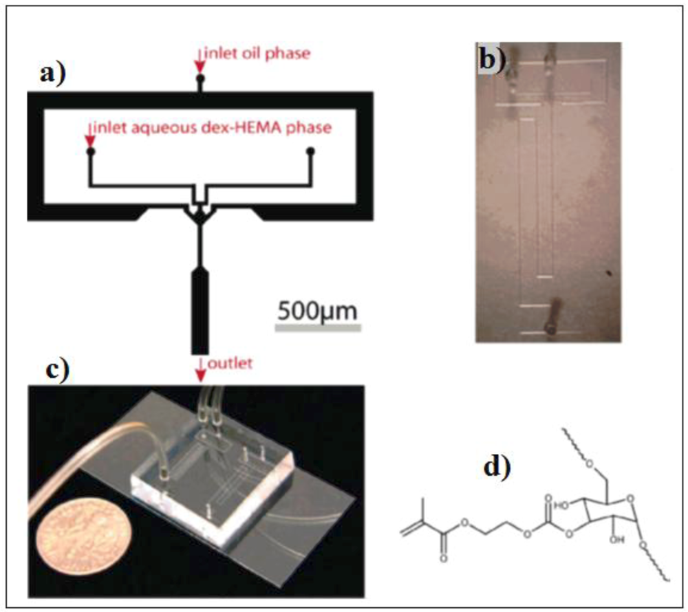
Microgels are promising materials in biomedicine and drug delivery applications as the release rate and profile of the drug molecules can be optimized for specific applications [47]. De Geest et al. fabricated 10 µm sized mono-disperse microgels in a PDMS device by emulsifying an aqueous dextran-hydroxyethyl methacrylate solution (dex-HEMA) within an oil phase (Figure 35).
Figure 35.
(a) Schematic representation of the PDMS microfluidic device with an in-line droplet generating nozzle; (b) Light microscopy image of the microfluidic channels illustrating channel layout and connection ports; (c) Image of the microfluidic device with the Tygon tubing attached to the PDMS-device; (d) Molecular structure of the dex-HEMA polymer (the Mw of the dex-HEMA is 19 kDa) [47].

The particularity of this work is that the curing by UV irradiation is done in a vial, outside of the device.
3.5. Hydrogels
Microfluidic technologies, mostly laminar flow-based multiple phase coaxial flowing systems have been used for various applications in tissue engineering for mimicking the tissue architecture [48].
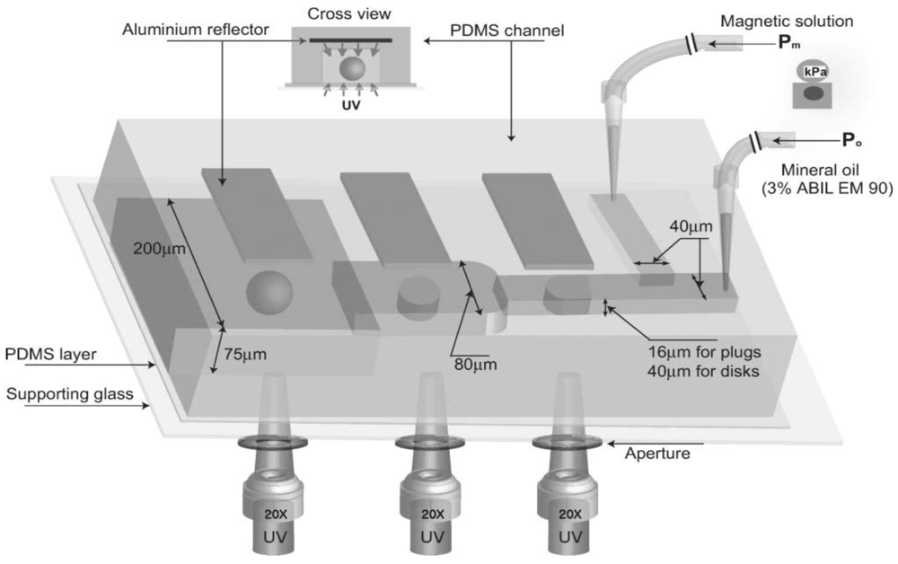
Doyle et al. [49] have synthesized magnetic hydrogel particles with different shapes (spheres, disks, and plugs) in a T-junction microfluidic device (Figure 36 and Figure 37).
Figure 36.
Schematic diagram of the T-junction microfluidic channel with aluminium reflectors for spherical and non-spherical magnetic hydrogel synthesis: sphere, disk, and plug. Pm indicates the input pressure for the hydrogel precursors (dispersed phase) and Po the input pressure for the mineral oil (continuous phase) [49].

Figure 37.
Optical images of (a) deformed spherical magnetic microhydrogels in the absence of the aluminium UV reflector; and (b–e) collections of magnetic microhydrogels in the presence of the aluminium UV reflector [47].
Figure 37.
Optical images of (a) deformed spherical magnetic microhydrogels in the absence of the aluminium UV reflector; and (b–e) collections of magnetic microhydrogels in the presence of the aluminium UV reflector [47].
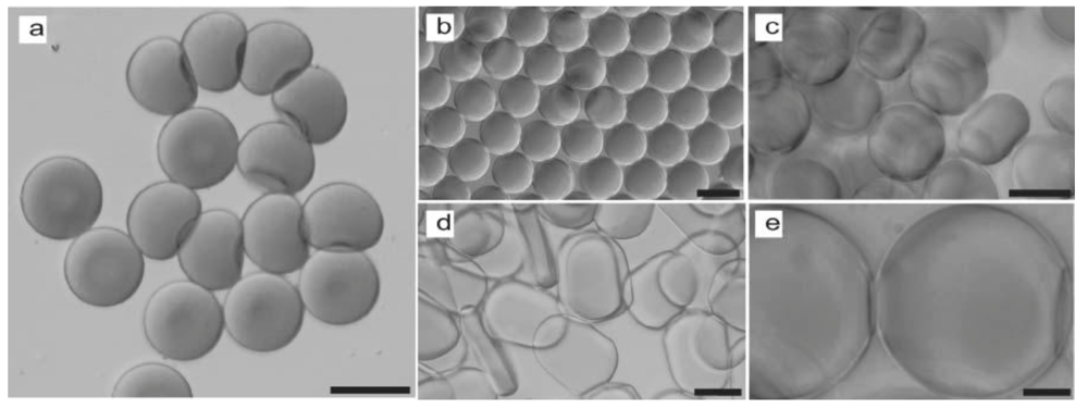
In order to improve the polymerization conditions, the device is used in combination with a UV light reflector (aluminium foil). The hydrogel particles, (both spherical and non-spherical), are monodisperse and have magnetic nanoparticles uniformly distributed inside the hydrogel. The hydrogelparticles synthesized in this way show super paramagnetic behavior.
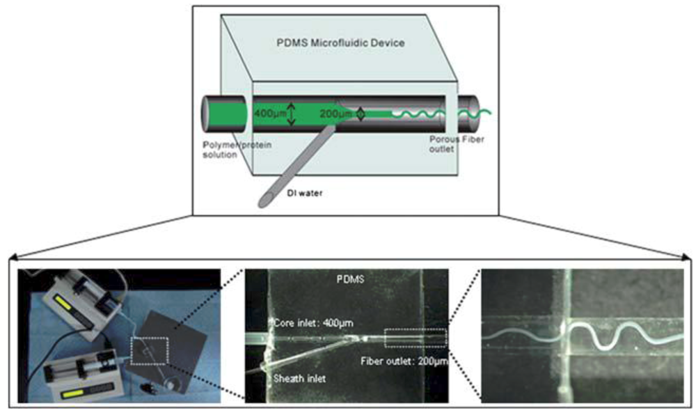
Porous microfibers were also fabricated using a simple PDMS-based microfluidic device in which an amphiphilic ABA triblock copolymer, poly(p-dioxanone-co-caprolactone)-block-poly(ethylene oxide)-block-poly(pdioxanone-co-caprolactone) (PPDO-co-PCL-b-PEG-b- PPDO-co-PCL) in dichloromethane and de-ionized water were introduced into the device and porous fibers were extruded through the outlet utilizing immersion precipitation and solvent evaporation.
Amphiphilic triblock copolymeric microfibers with a wide range of diameters (from 2 to 200 mm) were successfully extruded using the microfluidic device shown in Figure 38. The microfiber scaffolds were incorporated with fibronectin and the release behavior has been studied. The microfluidic technology is promising for use in biomedical applications such as tissue engineering scaffolds and drug delivery vehicles.
Figure 38.
Schematic illustration of fiber fabrication using the microfluidic device [50].
Figure 38.
Schematic illustration of fiber fabrication using the microfluidic device [50].
4. Conclusions and Outlook
The shift from the conventional synthesis and methods to the microfluidic strategy is taking place gradually. As shown in this short review that summarizes a part of the work done during the last decade, innovative microfluidic devices, fabrication strategies and technologies are coming up in the field of microfluidic synthesis. Screening a variety of reaction conditions, by varying flow rates, temperature, and reactant concentrations, microfluidics allowed the synthesis of a variety of monodisperse nanoparticles (metallic, semiconductors, polymers, nanocomposites) of a desired size and a well-determined shape. Both continuous flow and droplet-based microfluidic devices have been successfully used for producing nanoparticles of a desired structure and specific characteristics. While the continuous flow methods are widely used because of their simplicity and controllability, applications are limited due to the strong interactions with the walls and the possibility of channels blocking. The use of droplet-based microreactors can overcome these limitations and high quality nanoparticles can be successfully synthesized once the methodology is established. Compared to nanoparticles produced through conventional methods, the overall quality of materials prepared through microfluidic methods, appears to be much improved by the homogeneous reaction environment provided by microfluidics. The results obtained under different conditions demonstrated a considerably narrower size distribution in the case of microfluidic synthesis of both nano and microparticles. Generally, at high volumetric flow rates, narrower size distributions were found because the average residence time is inversely proportional to the flow rate.
The latest developments are concentrated in the field of polymers and inorganic-filled polymer microparticles (multicomponent compositions) with well-defined shapes and molecular weights, by control of device geometry and flow parameters.
Presently, microfluidic synthesis is beyond the demonstration of the proof-of-concept stage but, important steps have to be taken to bring about “beyond the lab bench” applications. Microfluidic production of nanoparticles and polymer microparticles is currently limited by the low productivity of a single device. The future developments of microfluidic synthesis will be oriented toward large-scale applications by using multiple parallel microfluidic reactors. For this, microfluidic devices should become more robust and reliable, and have to be integrated with a large variety of laboratory equipment for real on-chip functionality. Many efforts are underway to speed the transition from design stage to commercialization and to “bridge the divide between industry and academia” [51].
In spite of the remarkable progress toward microfluidic synthesis, we do not think that these advanced preparation methods will have to totally replace the traditional, well-established methods. Their development will evolve in parallel and the nano and microparticles synthesized through the two different approaches will find different applications. Microfluidic synthesis will become a method of choice only for applications that ask for special properties of materials.
The outlook is promising, and the microfluidic synthesis of nano and microparticles, together with the large-scale traditional methods, will open doors in the future to many new developments.
References
- Whitesides, G.M. Solving problems. Lab Chip 2010, 10, 2317–2318. [Google Scholar] [CrossRef]
- Whitesides, G.M. The origins and future of microfluidics. Nature 2006, 442, 368–373. [Google Scholar] [CrossRef]
- De Mello, A.J. Control and detection of chemical reactions in microfluidic systems. Nature 2006, 442, 394–402. [Google Scholar] [CrossRef]
- Park, J.; Saffary, A.; Kumar, S.; Günther, A.; Kumacheva, E. Microfluidic synthesis of polymer and inorganic particulate materials. Annu. Rev. Mater. Res. 2010, 40, 415–443. [Google Scholar] [CrossRef]
- Freemantle, M. Downsizing chemistry. Chem. Eng. News 1999, 77, 27–36. [Google Scholar]
- Zhao, C.X.; He, L.; Qiao, S.Z.; Middelberg, A.P.J. Nanoparticle synthesis in microreactors. Chem. Eng. Sci. 2011, 66, 1463–1479. [Google Scholar] [CrossRef]
- Jahn, A.; Reiner, J.E.; Vreeland, W.N.; de Voe, D.L.; Locascio, L.E.; Gaitan, M. Preparation of nanoparticles by continuous-flow microfluidics. J. Nanopart. Res. 2008, 10, 925–934. [Google Scholar] [CrossRef]
- Song, Y.; Kumar, C.S.S.R. Microfluidic synthesis of nanomaterials. Small 2008, 4, 698–711. [Google Scholar] [CrossRef]
- Haswell, S.; Middleton, R.J.; O’Sullivan, B.; Skelton, V.; Watts, P.; Styring, P. The application of micro reactors to synthetic chemistry. Chem. Commun. 2001, 5, 391–398. [Google Scholar]
- Stroock, A.D.; Dertinger, S.K.W.; Ajdari, A.; Mezir, I.; Stone, H.A.; Whitesides, G.M. Chaotic mixer for microchannels. Science 2002, 295, 647–651. [Google Scholar] [CrossRef]
- Hung, L.H.; Lee, A.P. Microfluidic devices for the synthesis of nanoparticles and biomaterials. J. Med. Biol. Eng. 2008, 27, 1–6. [Google Scholar]
- Stanley, C.E.; Wootton, R.C.R.; de Mello, A.J. Continuous and segmented flow microfluidics: Applications in high-throughput chemistry and biology. Chimia 2012, 66, 88–98. [Google Scholar] [CrossRef]
- Nakamura, H.; Yamaguchi, Y.; Miyazaki, M.; Maeda, H.; Uehara, M.; Mulvaney, P. Preparation of CdSe nanocrystals in a micro-flow-reactor. Chem. Comm. 2002, 23, 2844–2846. [Google Scholar]
- Wang, H.; Li, X.; Uehara, M.; Yamaguchi, Y.; Nakamura, H.; Miyazaki, M.; Shimizu, H.; Maeda, H. Continuous synthesis of CdSe-ZnS composite nanoparticles in a microfluidic reactor. Chem. Commun. 2004, 1, 48–49. [Google Scholar]
- Gomez-de Pedro, S.; Puyol, M.; Alonso-Chamarro, J. Continuous flow synthesis of nanoparticles using ceramic microfluidic devices. Nanotechnology 2010, 21. [Google Scholar] [CrossRef]
- Liu, K.K.; Wu, R.G.; Chuang, Y.J.; Khoo, H.S.; Huang, S.H.; Tseng, F.H. Microfluidic systems for Biosensing. Sensors 2010, 10, 6623–6661. [Google Scholar] [CrossRef]
- Abate, A.R.; Seiffert, S.; Utada, A.S.; Shum, A.; Shah, R.; Thiele, J.; Duncanson, W.J.; Abbaspourad, A.; Lee, M.H.; Akartuna, I.; Lee, D.; Rotem, A.; Weitz, D.A. Microfluidic Techniques for Synthesizing Particles. Available online: http://weitzlab.seas.harvard.edu/publications/Bookchapter_Microfluidic_techniques.pdf (accessed on 15 June 2012).
- Micronit Microfluidics Homepage. Available online: http://www.micronit.com/ (accessed on 18 June 2012).
- Song, H.; Chen, D.L.; Ismagilov, R.F. Reactions in droplets in microfluidic channels. Angew. Chem. Int. Ed. Engl. 2006, 45, 7336–7356. [Google Scholar] [CrossRef]
- Wagner, J.; Köhler, J.M. Continuous synthesis of gold nanoparticles in a micro-reactor. Nano Lett. 2005, 5, 685–691. [Google Scholar] [CrossRef]
- Wagner, J.; Tshikhudo, T.R.; Köhler, J.M. Microfluidic generation of metal nanoparticles by borohydride reduction. Chem. Eng. J. 2008, 135, S104–S109. [Google Scholar] [CrossRef]
- Shalom, D.; Wootton, R.C.R.; Winkle, R.F.; Cottam, B.F.; Vilar, R.; de Mello, A.J.; Wilde, C.P. Synthesis of thiol functionalized gold nanoparticles using a continuous flow microfluidic reactor. Mater. Lett. 2007, 61, 1146–1150. [Google Scholar]
- Polte, J.; Erler, R.; Thünemann, A.F.; Sokolov, S.; Torsten Ahner, T.; Rademann, K.; Emmerling, F.; Kraehnert, R. Nucleation and growth of gold nanoparticles studied via in situ small angle X-ray scattering at millisecond time resolution. ACS Nano 2010, 4, 1076–1082. [Google Scholar]
- Boleininger, J.; Kurz, A.; Reuss, V.; Sönnichsen, C. Microfluidic continuous flow synthesis of rod-shaped gold and silver nanocrystals. Phys. Chem. Chem. Phys. 2006, 8, 3824–3827. [Google Scholar]
- Lin, X.Z.; Terepka, A.D.; Yang, H. Synthesis of silver nanoparticles in a continuous flow tubular microreactor. Nano Lett. 2004, 4, 2227–2232. [Google Scholar] [CrossRef]
- Song, Y.; Doomes, E.E.; Prindle, J.; Tittsworth, R.; Hormes, J.; Kumar, C.S.S.R. Investigations into sulfobetaine-stabilized Cu nanoparticle formation: Toward development of a microfluidic synthesis. J. Phys. Chem.B 2005, 109, 9330–9339. [Google Scholar]
- Alsawafta, M.; SadAbadi, H.; Badilescu, S.; Pakirisamy, M.; Truong, V.V. Synthesis of stable copper nanoparticles in aqueous solution in a microfluidic reactor. In Proceedings of the 2nd International Conference on Nanotechnology: Fundamentals and Applications, Ottawa, Canada, 27–29 July 2011.
- Alsawafta, M.; Badilescu, S.; Packirisamy, M.; Truong, V.V. Kinetics at the nanoscale: Formation and aqueous oxidation of copper nanoparticles. Reac. Kinet. Mech. Cat. 2011, 104, 437–450. [Google Scholar] [CrossRef]
- Song, Y.; Modrow, H.; Henry, L.L.; Saw, C.K.; Doomes, E.E.; Palshin, V.; Hormes, J.; Kumar, C.S.S.R. Microfluidic synthesis of cobalt nanoparticles. Chem. Mater. 2006, 18, 2817–2827. [Google Scholar]
- Chan, E.M.; Mathies, R.A.; Alivisatos, A.P. Size-controlled growth of CdSe nanocrystals in microfluidic reactors. Nano Lett. 2003, 3, 199–201. [Google Scholar] [CrossRef]
- Duraiswamy, S.; Khan, S.A. Droplet-based microfluidic synthesis of anisotropic metal nanocrystals. Small 2009, 5, 2828–2834. [Google Scholar] [CrossRef]
- Nikoobakht, B.; El-Sayed, M.A. Preparation and growth mechanism of Gold Nanorods (NRs) using seed-mediated growth method. Chem. Mater. 2003, 15, 1957–1962. [Google Scholar] [CrossRef]
- Cabeza, V.S.; Kuhn, S.; Kulkarni, A.A.; Jensen, K.F. Size-controlled flow synthesis of gold nanoparticles using a segmented flow microfluidic platform. Langmuir 2012, 28, 7007–7013. [Google Scholar] [CrossRef]
- Miyazaki, M.; Yamaguchi, H.; Honda, T.; Briones-Nagata, M.P.; Yamashita, K.; Maeda, H. Polymer chemistry in microfluidic reaction system. Micro Nanosyst. 2009, 1, 193–204. [Google Scholar]
- Wu, T.; Mei, Y.; Cabral, J.T.; Xu, C.; Beers, K.L. A new synthetic method for controlled polymerization using a microfluidic system. J. Am. Chem. Soc. 2004, 126, 9880–9881. [Google Scholar]
- Iida, K.; Chastek, T.Q.; Beers, K.; Cavicci, K.A.; Chun, J.; Fasolka, M.J. Living anionic polymerization using a microfluidic reactor. Lab Chip 2009, 9, 339–345. [Google Scholar]
- Serra, C.A.; Chang, Z. Microfluidic-assisted synthesis of polymer particles. Chem. Eng.Technol. 2008, 31, 1099–1115. [Google Scholar] [CrossRef]
- Dendukuri, D.; Pregibon, D.C.; Collins, J.; Alan Hatton, T.; Doyle, P.S. Continuous-flow lithography for high-throughput microparticle synthesis. Nat. Mater. 2006, 5, 365–369. [Google Scholar] [CrossRef]
- Xu, S.; Nie, Z.; Seo, M.; Lewis, P.; Kumacheva, E.; Stone, H.A.; Garstecki, P.; Weibel, D.B.; Gitlin, I.; Whitesides, G.M. Generation of monodisperse particles by using microfluidics: Control over size, shape, and composition. Angew. Chem. Int. Ed. Engl. 2005, 44, 724–728. [Google Scholar]
- Rhee, M.; Valencia, P.M.; Rodriguez, M.I.; Langer, R.; Farokhzad, O.C.; Karnik, R. Synthesis of size-tunable polymeric nanoparticles enabled by 3D hydrodynamic flow focusing in single-layer microchannels. Adv. Mater. 2011, 23, H79–H83. [Google Scholar]
- Karnik, R.; Gu, F.; Basto, P.; Cannizzaro, C.; Dean, L.; Kyei-Manu, W.; Langer, R.; Farokhzaf, O.C. Microfluidic platform for controlled synthesis of polymeric nanoparticles. Nano Lett. 2008, 8, 2906–2912. [Google Scholar] [CrossRef]
- Dendukuri, D.; Tsoi, K.; Hatton, T.A.; Doyle, P.S. Controlled synthesis of nonspherical microparticles using microfluidics. Langmuir 2005, 21, 2113–2116. [Google Scholar]
- Chang, Z.; Li, S.; Bouquey, M.; Kraus, I.; Serra, C.A.; Köhler, J.M. Continuous-microflow synthesis of multiscale materials based on polymer microparticles/inorganic nanoparticle composites. In Proceedings of the 2nd WSEAS International Conference on Nanotechnology; World Scientific and Engineering Academy and Society (WSEAS): Stevens Point, WI, USA.
- SadAbadi, H.; Badilescu, S.; Packirisamy, M.; Wuthrich, R. Synthesis of gold nanoparticles in a microreactor environment. In Proceedings of NanoQuebec Conference, Montreal, QC, Canada, 20–21 March 2012.
- Ozhikandathil, J.; Badilescu, S.; Packirisamy, M. Gold nanoparticle integrated pdms microfluidic platform for bio-detection. In Proceedings of ICBME 2011, Manipal, India, 10–12 December 2011.
- Yang, C.H.; Huang, K.S.; Lin, Y.S.; Lu, K.; Tzeng, C.C.; Wang, E.C.; Lin, C.H.H.; Hsu, W.Y.; Chang, J.Y. Microfluidic-assisted synthesis of multi-functional polycaprolactone microcapsules: Incorporation of CdTe quantum dots, Fe3O4 super magnetic nanoparticles and tamoxifen anticancer drugs. Lab Chip 2009, 9, 961–965. [Google Scholar]
- De Geest, B.G.; Urbanski, J.P.; Thorsen, T.; Demeester, J.; de Smedt, S.C. Synthesis of monodisperse biodegradable microgels in microfluidic devices. Langmuir 2005, 21, 10275–10279. [Google Scholar]
- Chung, B.G.; Lee, K.H.; Khademhosseini, A.; Lee, S.H. Microfluidic fabrication of microengineered hydrogels and their application in tissue engineering. Lab Chip 2012, 12, 45–59. [Google Scholar] [CrossRef]
- Hwang, D.K.; Dendukuri, D.; Doyle, P.S. Microfluidic-based synthesis of non-spherical magnetic hydrogel microparticles. Lab Chip 2008, 8, 1640–1647. [Google Scholar] [CrossRef]
- Marimuthu, M.; Kim, S.; An, J. Amphiphilic triblock copolymer and a microfluidic device for porous microfiber fabrication. Soft Matter 2010, 6, 2200–2207. [Google Scholar] [CrossRef]
- Blow, N. Microfluidics: The great divide. Nat. Methods 2009, 6, 683–686. [Google Scholar] [CrossRef]
© 2012 by the authors; licensee MDPI, Basel, Switzerland. This article is an open-access article distributed under the terms and conditions of the Creative Commons Attribution license (http://creativecommons.org/licenses/by/3.0/).
Share and Cite
MDPI and ACS Style
Badilescu, S.; Packirisamy, M. Microfluidics-Nano-Integration for Synthesis and Sensing. Polymers 2012, 4, 1278-1310. https://doi.org/10.3390/polym4021278
AMA Style
Badilescu S, Packirisamy M. Microfluidics-Nano-Integration for Synthesis and Sensing. Polymers. 2012; 4(2):1278-1310. https://doi.org/10.3390/polym4021278
Chicago/Turabian StyleBadilescu, Simona, and Muthukumaran Packirisamy. 2012. "Microfluidics-Nano-Integration for Synthesis and Sensing" Polymers 4, no. 2: 1278-1310. https://doi.org/10.3390/polym4021278