Article

A Comparative Study on Physiochemical, Thermomechanical, and Electrochemical Properties of Sulfonated Poly(Ether Ether Ketone) Block Copolymer Membranes with and without Fe3O4 Nanoparticles

1
Department of Bioenvironmental Chemistry and R&D Center for CANUTECH, Business Incubation Center, Chonbuk National University, Jeollabuk–do 54896, Korea
2
Graduate School, Department of Energy Storage/Conversion Engineering and Hydrogen and Fuel Cell Research Center, Chonbuk National University, Jeollabuk-do 54896, Korea
3
Department of Life Science, Chonbuk National University, Jeollabuk–do 54896, Korea
*
Author to whom correspondence should be addressed.
Polymers 2019, 11(3), 536; https://doi.org/10.3390/polym11030536
Submission received: 1 March 2019 / Revised: 16 March 2019 / Accepted: 19 March 2019 / Published: 21 March 2019

Abstract

:
The composite structure, good porosity, and electrochemical behavior of proton exchange membranes (PEMs) are important characteristics, which can improve the performance of polymer electrolyte fuel cells (PEFCs). In this study, we designed and synthesized an XY block copolymer via a polycondensation reaction that contains sulfonated poly(ether ether ketone) (SPEEK) (X) as a hydrophilic unit and a fluorinated oligomer (Y) as a hydrophobic unit. The prepared XY block copolymer is composed of Fe3O4 nanoparticles to create composite architecture, which was subsequently treated with a 1 M H2SO4 solution at 70 °C for 1 h to eliminate Fe3O4 and generate a pores structure in the membrane. The morphological, physiochemical, thermomechanical, and electrochemical properties of bare XY, XY/Fe3O4-9 and XY(porous)-9 membranes were measured and compared in detail. Compared with XY/Fe3O4-9 composite, the proton conductivity of XY(porous)-9 membrane was remarkably enhanced as a result of the existence of pores as nano-conducting channels. Similarly, the XY(porous)-9 membrane exhibited enhanced water retention and ion exchange capacity among the prepared membranes. However, the PEFC power density of XY(porous)-9 membrane was still lower than that of XY/Fe3O4-9 membrane at 60 °C and 60% relative humidity. Also, the durability of XY(porous)-9 membrane is found to be lower compared with pristine XY and XY/Fe3O4-9 membranes as a result of the hydrogen crossover through the pores of the membrane.

Graphical Abstract

1. Introduction

Environmental pollution is a severe threat to all countries owing to increasing emanation of green-house gases from the incineration of fossil fuels [1,2,3]. On the other hand, fuel cells are a green energy technology that converts chemical energy directly into electrical energy in a single step [4]. Among various types of fuel cells, polymer electrolyte fuel cells (PEFCs) are being considered as a promising technology because of their high power density, high conversion efficiency, and rapid start-up and shut-down times [5,6]. Proton exchange membranes (PEMs) are gaining popularity in PEFCs because of their favorable proton conductivity and gas barrier properties. For example, Nafion is the state-of-the-art membrane used in PEFCs because of its long-term durability, high electrical insulation, high proton conductivity, excellent dimensional stability, and good chemical stability. Regardless of its benefits, the proton conductivity of Nafion decreases dramatically at high temperatures or low relative humidity (RH) because of its inability to retain water molecules [7].
Recently, researchers have developed various alternative PEMs consisting of aromatic hydrocarbon polymers, such as sulfonated poly(imide), sulfonated poly(arylene ether sulfone) sulfonated poly(phenylene), and sulfonated poly(ether ether ketone) (SPEEK) [8]. Although the hydrocarbon polymer-based PEMs exhibit admirable performance, their usage come with a difficult trade-off between ion conductivity and dimensional stability [9]. Exploiting block copolymer PEMs consisting of both hydrophilic and hydrophobic units is a fascinating strategy that has been proposed to alleviate the trade-off between ion conductivity and dimensional stability [10]. In general, the synthesis of a block copolymer involves nucleophilic substitution between oligomers and the subsequent polymerization process, which results in the formation of block copolymer structure with extended polymer chains [11]. In a block structure, the ionic channels are generated as a result of phase separation, which can facilitate the transport of protons. Additionally, inorganic–organic composite PEMs have gained the attention of researchers because of their advantages in mechanical strength and thermal stability [12]; the composite PEMs can combine the advantages of both the organic matrix and the inorganic fillers. Various types of inorganic fillers, including SiO2, TiO2, ZrO2, Fe3O4, CeO2, and Al2O3, have been exploited as additives to enhance the comprehensive performance of PEMs [13]. Specifically, Fe3O4 nanoparticles have the advantages of high electrical conductivity and electrocatalytic activity, thus it has been widely used in various electrochemical applications. Also, the –OH groups on the surface of Fe3O4 make good interactions with polymer chains that improve the membrane’s properties [14,15,16]. On the other hand, the creation of porous structures in aromatic membranes is one of the best strategies to enhance the water uptake in membranes [4]. Materials that contain ordered and interconnected nano-pores have efficient and selective proton transport, which is a critical benefit in PEFCs. State-of-the-art Nafion is a well-known porous membrane that possesses connective proton transport channels [17]. As they comprise the optimal arrangement of proton transport sites, connective proton transport channels are distributed, which results in high proton conductivity.
Inspired by the previously mentioned properties, in the present work, we created pores in the membranes by incorporating and subsequently dissolving 30 nm Fe3O4 nanoparticles. We report the synthesis of an XY block structure, wherein X was the SPEEK as a hydrophilic unit and Y was the fluorinated poly(arylene isopropylidenediphenol biphenyl) oligomer as a hydrophobic unit using nucleophilic substitution strategy. Further, the composite membrane was fabricated by blending the XY block copolymer with 30 nm Fe3O4 nanoparticles. The porous membrane was then created by dissolving Fe3O4 nanoparticles by immersing composite membrane into 1 M H2SO4 at 70 °C for 1 h. The successful formation of SPEEK, hydrophobic oligomer, and XY block copolymer were verified with proton nuclear magnetic resonance (1H NMR) analysis. The effects of pores on structural, morphological, thermal, and mechanical properties of membranes were also examined using corresponding analytical techniques. The physiochemical properties were evaluated in terms of water uptake, swelling ratio, ion exchange capacity, and water contact angle to show the improvements due to the porous structure of the membrane. The electrochemical properties were investigated in terms of proton conductivity and PEFC performance to test the suitability of the porous membrane for use in fuel cell applications. We have compared all the obtained physiochemical, thermomechanical, and electrochemical properties of membranes with and without Fe3O4 to find better PEMs for PEFC application.

2. Experimental Section

2.1. Materials

Poly(ether ether ketone) (PEEK) powder was purchased from Victrex Company, South Korea. 4,4′-hexafluoroisopropylidenediphenol (HFIP) and decafluorobiphenyl (DFBP), N,N-dimethylacetamide (DMAc), N,N-dimethylformamide (DMF) dimethyl sulfoxide (DMSO), N-methylpyrrolidinone (NMP), anhydrous potassium carbonate (K2CO3), and toluene were derived from Sigma-Aldrich, South Korea and used without further purification. Other reagents and solvents were exploited as obtained.

2.2. SPEEK (X) and Hydrophobic Oligomer(Y) Synthesis

To produce the X component, we utilized the same reaction conditions and work-up procedures as those given in the literature [18]. The prepared X component was then immersed into a 0.1 M NaCl solution to exchange H+ with Na+. The Na salt form of X was dried and stored for later use. Then, 2.017 g (6.0 mmol) of HFIP, 2.0 g (6.0 mmol) of DFBP, 1.66 g (12.0 mmol) of K2CO3, 11 mL of DMAc, and 20 mL of toluene were charged together in a three-necked round-bottomed flask that was fitted with all of the required equipment. The reaction was performed at 120–160 °C in an oil bath under a N2 atmosphere with constant stirring (300 rpm). The solid product was cleaned with a mixture of methanol, acetone, and deionized (DI) water to remove the low molecular weight substances. Subsequently, the obtained component Y was dried and stored for later use.

2.3. XY Block Copolymer Synthesis

A total of 0.714 g (5.0 × 10⁻³ mmol) of the Na salt form of X was mixed and magnetically stirred under a N2 atmosphere with 0.123 g (5.0 × 10⁻³ mmol) of component Y in 9 mL of DMAc and 20 mL toluene solvents. Then, 0.028 g (0.2 mmol) of K2CO3 was gradually added to the mixture while magnetic stirring. Next, the mixture was heated under reflux (300 rpm) at 120–140 °C for 10 h to dehydrate the system. The reaction temperature was then increased to 165 °C, where it was maintained for 14 h. During that time, the solution became very viscous [19]. The solid product was cleaned with a mixture of methanol, acetone, and DI water to remove the low molecular weight substances and dried to furnish a XY block copolymer. XY: 1H NMR (600 MHz, DMSO-d6) δ 7.83–7.69, 7.5–7.44, 7.4–7.3, 7.3–6.9. Afterwards, the obtained XY block copolymer was soaked in 0.5 M H2SO4 for 12 h to exchange the Na+ with H+ ions.

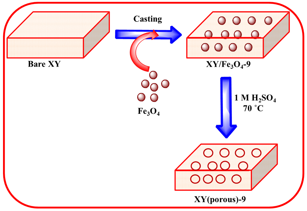
2.4. Membrane Preparation

Fe3O4 nanoparticles were prepared using a co-precipitation method as previously described in the literature [20]. Scheme 1 shows the preparation process of composite membrane. Approximately, 0.5 g of the XY block copolymer was initially dissolved in 10 mL DMF using magnetic stirring. Afterward, 3 wt%, 9 wt%, or 12 wt% of Fe3O4 was dispersed into the solution by sonication to obtain a composite solution. The resulting solution was stirred at 70 °C for desired time to prepare the casting solution. Then, the obtained solution was poured into a glass dish and dried in an oven at 70 °C for 12 h to evaporate the solvent. The prepared composite membrane was peeled off the glass dish via immersion in DI water. Next, the composite membrane was immersed in 1 M H2SO4 at 70 °C for 1 h to dissolve Fe3O4 nanoparticles and create pores in the membrane. Finally, the membranes were again immersed into DI water to uptake water in the pores. The XY/Fe3O4-9 membrane is brown in color and magnetically active (Figure 1b,e), while the bare and XY(porous)-9 membranes are yellow in color and magnetically inactive (Figure 1a,d,c,f). The thickness of the membranes was measured at least three points and was 50–60 µm.

3. Characterizations

The below mentioned instruments except SAXS, GPC and UTM were installed in the center for university-wide research facilities (CURF) at Chonbuk national university (CBNU).

3.1. Structural Characterizations

Proton nuclear magnetic resonance (1H NMR, JNM-ECA600-600 MHz) was used to ensure the chemical structure of the polymers with anhydrous DMSO-d6 as solvent. Fourier transform infrared spectroscopy (FT-IR, Perkin Elmer, Frontier) was utilized to examine the functional groups in the membranes. High-resolution X-ray diffractometry (XRD, X’Pert MRD with CuKα radiation) was used to analyze the crystalline structure of the membrane samples. Small angle X-ray scattering (SAXS, EMPYREAN, Malvern Panalytical) was used to measure the average ionic cluster dimensions. Gel permeation chromatography (GPC, HLC‒8320GPC‒Tosoh Corporation, Tokyo, Japan) was used to measure the molecular weights of the synthesized oligomers and polymers.

3.2. Morphological Characterizations

The morphological properties of the prepared membranes were studied using a field emission scanning electron microscope (FE-SEM, SUPRA 40VP) furnished with an energy dispersive X-ray (EDX) spectrometer.

3.3. Thermal and Mechanical Characterizations

The thermogravimetric analysis (TGA) was performed with a Q50 thermal instrument under a N2 atmosphere at a heating rate of 5 °C/min to examine the thermal stability of membrane and filler samples; and a LR5K plus 5 kN universal testing machine (UTM, Ametek Lioyd Instruments, Ltd.) was used to test the mechanical properties of dry membranes (30 mm × 15 mm) at a strain rate of 10 mm/min. We used two different samples for each membrane to check the reproducibility of curves.

4. Measurements

4.1. Water Uptake

Water uptake measurements were performed to examine the water retention ability of membranes. The dry membrane samples were weighed and immersed into DI water and kept for 24 h at 30 °C. Afterwards, the wet membrane samples were removed from the DI water and weighed again. The water uptake of the membrane calculated using the following formula [21]:
Water   uptake   of   the   membrane   ( % )   =   [ W wet W dry W dry ] ×   100 ,
where Wwet is the weight (mg) of the wet membrane and Wdry is the weight (mg) of the dry membrane.

4.2. Swelling Ratio

The swelling ratio in length (SL), area (SA), and volume (SV) was measured according to the change in volume of the membrane samples before and after water uptake. The swelling ratio of the membrane samples was calculated with the following formula [22,23,24]:
Swelling   ratio   in   length   =   [ L wet   L dry L dry ] ×   100 ,
Swelling   ratio   in   area   =   [ A wet   A dry A dry ] ×   100 ,
Swelling   ratio   in   volume   =   [ V wet   V dry V dry ] ×   100 ,
where Lwet, Awet, and Vwet are the length, area, and volume of the wet membranes; and Ldry, Adry, and Vdry are the length, area, and volume of the dry membranes.

4.3. Ion Exchange Capacity

Ion exchange capacity (IEC) determines the number of milliequivalents of ions that are present per 1 g of dry membrane [25]. The IECs of the prepared membranes were determined using a titration method. To perform this measurement, the dried membrane was soaked in a 0.1 M NaCl solution for 24 h to exchange H+ with Na+ ions. Then, the liberated H+ ions were titrated with a 0.01 M NaOH solution using phenolphthalein as indicator. The IEC was calculated according to the following equation:
IEC   of   the   membrane   ( meq / g )   =   [ Volume   of   NaOH   consumed   ×   Consendration   NaOH Weight   of   dry   membrane ] .

4.4. Contact Angle

The contact angle measurements were performed on the prepared samples using a DSA10 instrument (Kruss GmbH, Germany) to identify the wettability or hydrophilicity of membrane surface.

4.5. Proton Conductivity

The proton conductivity of membrane samples was measured at 100% RH and different temperatures ranging from 40 to 80 °C using a four-electrode BekkTech cell equipped with an alternating current impedance spectroscope [26,27,28]. Proton conductivity (σ) was calculated via the following formula:
Proton   conductivity   of   the   membrane   ( mS / cm )   =   [ L RTW ] ,
where L (cm) is the distance between the electrodes, R (ohm) is the resistance of membrane, T (cm) is the thickness of the membrane, and W (cm) is the width of the membrane.

4.6. Fabrication of Membrane Electrode Assembly and PEFC Test

The PEFC performance was tested using a fuel cell machine (Horizon Fuel Cell Technologies, Model: SKFC-TS001, South Korea) at 60 °C and 60% relative humidity under atmospheric pressure. In brief, the membrane–electrode assembly (MEA) was prepared through the conventional hot-pressing technique with commercial gas diffusion electrodes (GDE) (Pt catalyst loading of 0.3 mg/cm2). Membranes were tightened with the GDEs and hot-pressed at 100 °C for 3 min with a pressure of 100 kg/cm2. The active area of the obtained MEA was 5 cm2, which was fixed in PEFC device and tested the performance. H2 gas and air were passed at 100 and 400 mL/min for the corresponding anode and cathode, respectively.

5. Results and Discussion

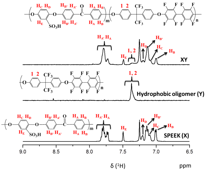
5.1. Structural Properties

We controlled the X and Y components in the prepared XY block copolymers at a 1:1 molar ratio. X, Y, and XY block copolymers exhibited molecular weights (Mw) of 142,800, 20,100, and 164,100, respectively, and the polydispersity index (PDI) (Mw/Mn) values for the X, Y, and XY block copolymers were 2.2, 4.1, and 3.3, respectively (Table 1). The chemical structures of synthesized polymers identified by 1H NMR spectroscopy are shown in Figure 2. The proton peaks of X were observed between 6.9 to 7.9 ppm in the 1H NMR spectrum, corresponding to aromatic protons. In addition, the successful attachment of SO3H groups was verified by the peak at 7.5 ppm, and the degree of sulfonation (DS) was calculated as 42% using this peak. Similarly, the XY block copolymer had significant signals in the range of 6.9 to 7.9 ppm, which arose from the aromatic protons of both SPEEK and the hydrophobic units. Functional groups of pristine and composite membrane were identified by FT-IR (Figure S2). The bands found about 1004 and 1015 cm−1 in the XY spectrum were consigned to the symmetric stretching vibration of in-chain diphenyl ether (Ar–O–Ar) existing in the para-substituted benzene ring of the Y part [29]. The peaks at 1223, 1069, and 1009 cm−1 are associated with the asymmetric and symmetric stretching of sulfone in SO3H from the X part. These bands confirmed the formation of the XY structure. Along with the aforementioned bands, the Fe–O stretching at 520 cm−1 was also observed in the composite membrane [30], indicating the formation of the composite membrane. Again, the Fe–O stretching disappeared in the case of the XY/(porous)-9 membrane, verifying the successful removal of Fe3O4 by acid treatment. The XRD patterns of XY, XY/Fe3O4-9, and XY(porous)-9 were investigated to evaluate the crystalline structure of prepared materials (Figure 3). When compared with the XY membrane, the XY/Fe3O4-9 membrane exhibits additional peaks of 200, 400, 511, and 111 planes related to Fe3O4. Such a result confirms the successful formation of the composite structure. As further validation, the aforementioned Fe3O4 planes disappeared for the XY(porous)-9 sample as a result of the acid treatment. On the other hand, the ionic cluster dimensions of bare and composite membranes were confirmed using SAXS [31], and similar ionic cluster dimensions were observed in both the bare XY and composite membranes, as shown in Figure 4.

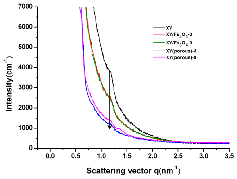
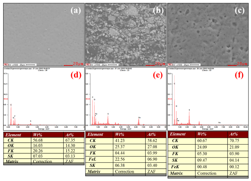
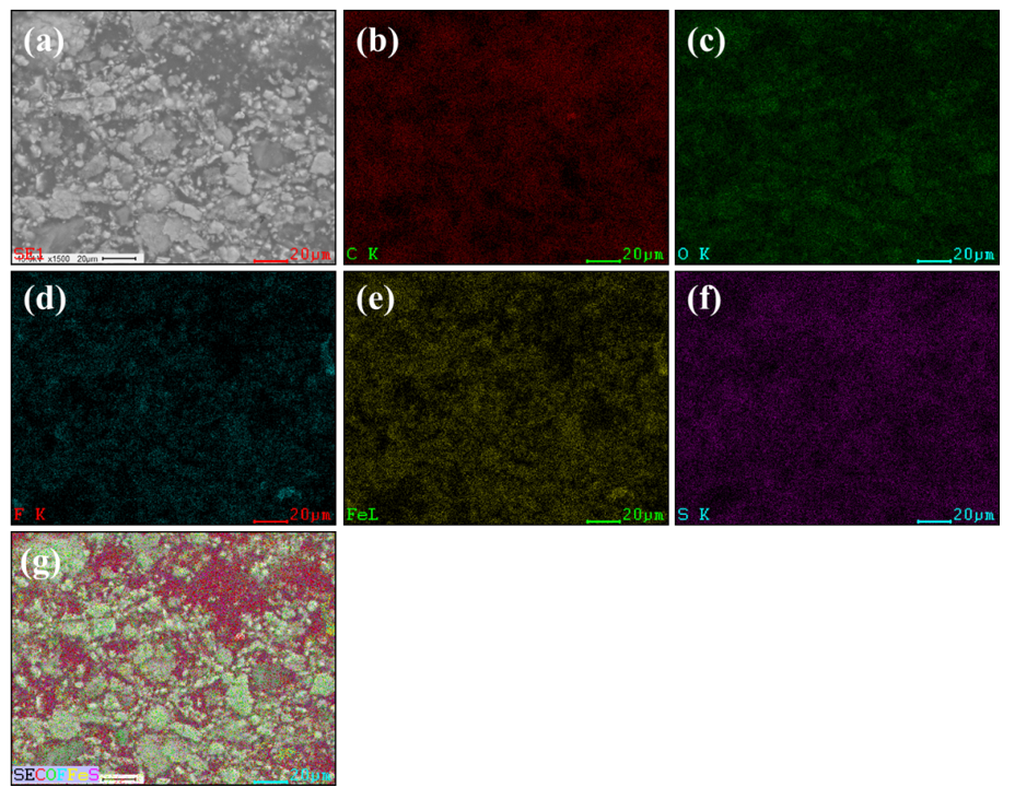
5.2. Morphological Properties

The morphologies of Fe3O4 nanoparticles and membranes were investigated using TEM and FE-SEM, and the results are demonstrated in Figure 5 and Figure 6. Using this analysis, we observed the Fe3O4 nanoparticles with the size of 30 nm, demonstrating that the successful formation of Fe3O4 nanoparticles via the co-precipitation method. The XY membrane shows a clean morphology where there are no cracks, pinholes, or perforations observed, indicating the formation of an efficient membrane (Figure 6a). Compared with the bare XY membrane, the composite membrane has a rough surface due to the existence of Fe3O4 nanoparticles (Figure 6b). After treatment with 1 M H2SO4 at 70 °C, the Fe3O4 nanoparticles dissolved and, consequently, pores were generated on the surface (Figure 6c). Such pores act as nano-channels for the efficient transfer of protons. To investigate the dispersibility of Fe3O4 or pores across the cross-section of the membranes, the cross-sectional FE-SEM images were observed, as given in Figure S1a–i (Supplementary Materials). The Fe3O4 nanoparticles and pores were randomly dispersed in the cross-section of the membranes. EDX elemental analysis was performed to investigate the porous structure in the membranes. As shown in Figure 6f, the Fe3O4 nanoparticles were dissolved successfully using an acid treatment. According to the elemental mapping images (Figure 7), the Fe3O4 particles were spread across the surface of membrane, which might increase the membrane porosity.

5.3. Thermal and Mechanical Properties

The TGA results are shown in Figure 8. The TGA curves show three stages of thermal degradation in the prepared samples. The first stage of degradation occurred in the temperatures range of 30–200 °C due to the thermal decomposition of free water molecules in samples [32]. The second stage of degradation took place between 220–400 °C and can be attributed to the thermal decomposition of SO3H groups in the samples [33,34]. The final degradation stage occurred at temperatures above 500 °C due to the decomposition of the polymer backbone. The prepared XY/Fe3O4-9 composite membrane showed higher thermal stability than the bare XY membrane because of the presence of thermally-stable Fe3O4 nano-fillers. After removal of Fe3O4 nanoparticles via acid treatment, the porous XY membrane degraded rapidly. The mechanical stabilities of membranes were measured at a dry state at room temperature (Figure 9). The stress of XY is acceptable; however, once the XY backbone was blended with Fe3O4, the increased stress was observed, which may be ascribed to electrostatic interactions between the polymer chains and Fe3O4. Nevertheless, a lower strain in the XY/Fe3O4-9 indicates its high brittleness. On other hand, the XY(porous)-9 membrane exhibits high strain because of its high flexibility across the membrane provided by the porous architecture [18]. Thus, it is believed that XY(porous)-9 has a high plasticization nature, which causes the membrane to have high strain.

5.4. Water Uptake, Swelling Ratio, IEC, and Contact Angle

The water uptake, swelling ratio, IEC, and contact angle measurements are essential factors in determining the suitability of a membrane for PEFC applications (Table 2) [22]. The proton conductivity of membranes is closely correlated to water uptake; a membrane that contains a greater quantity of water molecules can facilitate proton transport via vehicle mechanism. The bare XY membrane shows a water uptake of 11.9%, while water uptakes of 16.7% and 26.6% were observed for XY/Fe3O4-9 and XY(porous)-9 membranes, respectively. The higher water uptake for the porous membrane is the result of the existence of pores in membranes, which accommodate the water molecules. In general, the amount of water absorption depends directly on the amount of hydrophilic channels in a membrane, and the amount of hydrophilic channels in a membrane is directly proportional to the degree of sulfonation. Likewise, the swelling ratio exhibits a similar dependency to that of water uptake. Compared with the bare XY membrane, the XY/Fe3O4-9 and XY(porous)-9 membranes revealed high swelling degrees in length, area, and volume, owing to the higher water uptake. Furthermore, IEC is closely related to the density of sulfonic acid groups in the membrane. The IEC value of the XY membrane was 1.24 meq/g, and it was 1.41 meq/g and 1.81 meq/g for the XY/Fe3O4-9 and XY(porous)-9 membranes, respectively. Hence, the proton conductivity of the XY(porous)-9 membrane (124.2 mS/cm) is much higher than that of the bare XY membrane (71.5 mS/cm) and XY/Fe3O4-9 (83.9 mS/cm) at 80 °C. Contact angle images of prepared membranes are shown in Figure 10. When compared with the XY membrane, the XY/Fe3O4-9 membrane sample shows a lower contact angle due to the existence of Fe3O4 nanoparticles. Interestingly, the XY(porous)-9 membrane exhibits an even lower contact angle, likely because of the pores in the membrane

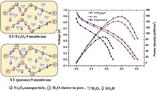
5.5. Proton Conductivity and PEFC Performance and Durability

In PEMFC, the proton conductivity of a membrane is considered as one of the most influential properties. It is believed that the enhancement in proton conductivity of a membrane leads to improvements in the total power density of a cell [35]. Typically, PEM proton conductivity follows two mechanisms: (i) the vehicle mechanism and (ii) the Grotthuss mechanism [36]. In the vehicle mechanism, hydrogen bonding in the polymer matrix is considered to be responsible for the transportation of H+ ions [37]. In high humidity conditions, the water molecules absorbed onto the wet membrane will react with the hydrogen bonds in polymer matrix and become hydronium (H3O+) ions. In the Grotthuss mechanism, the H3O+ ions are thought to be responsible for the transportation of protons in membrane [38]. In this study, all of the prepared membranes exhibited both types of proton transport mechanisms. Figure 11 shows the temperature dependency of proton conductivity in the prepared membranes. The proton conductivity was observed to increase with increasing cell temperatures for all prepared membranes. From the curves, it is apparent that the XY(porous)-9 has a higher proton conductivity (124.2 mS/cm at 80 °C) than the other prepared membranes as a result of the domination of the vehicle mechanism. Furthermore, the nano-pores in polymer matrix may facilitate the absorption of excess water molecules and, consequently, facilitate proton transport via the vehicle mechanism. In the case of the XY(porous)-12 membrane, however, the proton conductivity is lower because of the aggregated pore structure. Therefore, we hypothesize that the high distribution and aggregation of pores may lower the proton conductivity of the membrane. On the other side, XY/Fe3O4 membranes exhibit higher conductivity than the bare XY membrane, indicating that Fe3O4 nanoparticles help to facilitate the conductivity in the membrane. The PEFC performance of bare XY, XY/Fe3O4-9, and XY(porous)-9 membranes was compared at 60 °C under 60% relative humidity, and the respective polarization curves are plotted in Figure 12. XY/Fe3O4-9 achieved the highest maximum power density of 159 mW/cm2 at a load current density of 299 mA/cm2, followed by bare XY (142 mW/cm2) and XY(porous)-9 (88.5 mW/cm2) at the load current densities of 276 mA/cm2 and 176 mA/cm2, respectively. The primary reason for the lower power density of the porous membrane might be the high fuel crossover through the membrane. The pores in the XY(porous)-9 membrane allow the protons along with hydrogen, hence the power density the membrane is observed to be lower. The durability data of the prepared membranes were recorded at 60 °C under 60% relative humidity over 70 h, and the obtained results are provided in Figure S3. The total voltage decays of pristine XY, XY(Fe3O4)-9, and XY/(porous)-9 membranes are 0.35, 0.76, and 0.27 V, respectively. Compared with pristine XY and XY/(porous)-9 membranes, the composite membrane exhibits a high voltage decay because of the existence of Fe3O4. Fe3+ and Fe4+ ions in the Fe3O4 catalyze the radicals generation in the cell. Such radicals attach the membranes and accelerate the chemical degradation. Consequently, the membranes exhibit high voltage decay.

6. Conclusions

In this study, hygroscopic Fe3O4 nanoparticles were synthesized via the co-precipitation method and doped onto an XY block copolymer matrix to fabricate a novel PEM. Furthermore, we created a porous structure in the XY matrix by removing Fe3O4 nanoparticles by immersing a membrane in a 1 M H2SO4 solution at 70 °C for 1 h. When comparing the bare XY and XY(porous)-9 membranes, the XY/Fe3O4-9 membrane shows high stress and a significant improvement in mechanical strength and thermal stability. Although XY(porous)-9 membrane show improved water uptake, proton conductivity, and IEC, the PEFC performance of XY(porous)-9 is observed to be lower. Thus, we justify that the XY/Fe3O4-9 membrane is more suitable for PEFC device applications than the XY(porous)-9 membrane. As a result, the present study provides valuable information about the fabrication and comparison of physiochemical, thermomechanical, and electrochemical properties of the XY/Fe3O4-9 and XY(porous)-9 membranes. Thus, this study might assist to understand the importance of the XY/Fe3O4-9 or XY(porous)-9 membrane for their wide application in PEFCs.

Supplementary Materials

The supplementary materials are available online at https://www.mdpi.com/2073-4360/11/3/536/s1.

Author Contributions

A.R.K. prepared the polymers and PEMs; and performed and analyzed the 1H-NMR, FE-SEM, AFM, TGA, UTM, water contact angle, proton conductivity, and PEFC. D.J.Y. contributed to manuscript preparation.

Acknowledgments

This work was supported by the Korea Institute of Energy Technology Evaluation and Planning (KETEP) and the Ministry of Trade, Industry, & Energy (MOTIE) of the Republic of Korea (No. 20184030202210). This work was supported by grants from the Medical Research Center Program (NRF-2017R1A5A2015061) through the National Research Foundation (NRF), which is funded by the Korean government (MSIP).

Conflicts of Interest

The authors declare that they have no conflict of interest.

References

  1. Tang, Y.; Bi, L.; Mortimer, R.J.G.; Pan, G. Cryogenic circulation for indoor air pollution control. Sci. Total Environ. 2019, 651, 1451–1456. [Google Scholar] [CrossRef]
  2. Bruce, N.; Padilla, R.P.; Albalak, R. Indoor air pollution in developing countries: A major environmental and public health challenge. B World Health Organ. 2000, 78, 1078–1092. [Google Scholar]
  3. Sivanjineyulu, V.; Chang, Y.-H.; Chiu, F.-C. Characterization of carbon nanotube- and organoclay-filled polypropylene/poly(butylene succinate) blend-based nanocomposites with enhance rigidity and electrical conductivity. J. Polym. Res. 2017, 24, 130. [Google Scholar] [CrossRef]
  4. Dresselhaus, M.S.; Thomas, I.L. Alternative energy technologies. Nature 2001, 114, 332–337. [Google Scholar] [CrossRef]
  5. Mehta, V.; Cooper, J.S. Review and analysis of PEM fuel cell design and manufacturing. J. Power Source 2003, 114, 32–53. [Google Scholar] [CrossRef]
  6. Chen, H.; Cong, T.N.; Yang, W.; Tan, C.; Li, Y.; Ding, Y. Progress in electrical energy storage system: A critical review. Prog. Nat. Sci. 2009, 19, 291–312. [Google Scholar] [CrossRef]
  7. Mishra, A.K.; Kim, N.H.; Jung, D.; Lee, J.H. Enhanced mechanical properties and proton conductivity of Nafion–SPEEK–GO composite membranes for fuel cell applications. J. Membr. Sci. 2014, 458, 128–135. [Google Scholar] [CrossRef]
  8. Matsumoto, K.; Higashihara, T.; Ueda, M. Locally and densely sulfonated poly(ether sulfone)s as proton exchange membrane. Macromolecules 2009, 42, 1161–1166. [Google Scholar] [CrossRef]
  9. Hickner, M.A.; Ghassemi, H.; Kim, Y.S.; Einsla, B.R.; McGrath, J.E. Alternative polymer systems for proton exchange membranes (PEMs). Chem. Rev. 2004, 104, 4587–4612. [Google Scholar] [CrossRef]
  10. Peckham, T.J.; Holdcroft, S. Structure-morphology-property relationships of non-perfluorinated proton-conducting membranes. Adv. Mater. 2010, 22, 4667–4690. [Google Scholar] [CrossRef]
  11. Chattopadhyay, D.K.; Kothapalli, R.V. Structural engineering of polyurethane coatings for high performance applications. Prog. Polym. Sci. 2007, 32, 352–418. [Google Scholar] [CrossRef]
  12. Robert, C.L.; Valle, K.; Pereir, F.; Sanchez, C. Design and properties of functional hybrid organic-inorganic membranes for fuel cells. Chem. Soc. Rev. 2011, 40, 961–1005. [Google Scholar] [CrossRef] [PubMed]
  13. Nagarale, R.K.; Shin, W.; Singh, P.K. Progress in ionic organic-inorganic composite membranes for fuel cell applications. Polym. Chem. 2010, 1, 388–408. [Google Scholar] [CrossRef]
  14. Ulbricht, M. Advanced functional polymer membranes. Polymer 2006, 47, 2217–2262. [Google Scholar] [CrossRef] [Green Version]
  15. Yadav, M. Study on thermal and mechanical properties of cellulose/iron oxide bionanocomposites film. Compos. Commun. 2018, 10, 1–5. [Google Scholar] [CrossRef]
  16. Yadava, M.; Muna, S.; Hyunb, J.; Kima, J. Synthesis and characterization of iron oxide/cellulose nanocomposite film. Int. J. Biol. Macromolecules 2015, 74, 142–149. [Google Scholar] [CrossRef]
  17. Jain, M.; Yadav, M.; Kohout, T.; Lahtinen, M.; Garg, V.K.; Sillanpa, M. Development of iron oxide/activated carbon nanoparticle composite for the removal of Cr(VI), Cu(II) and Cd(II) ions from aqueous solution. Water Resour. Ind. 2018, 20, 54–74. [Google Scholar] [CrossRef]
  18. Vinothkannan, M.; Kim, A.R.; Nahm, K.S.; Yoo, D.J. Ternary hybrid (SPEEK/SPVdF-HFP/GO) based membrane electrolyte for the applications of fuel cells: Profile of improved mechanical strength, thermal stability and proton conductivity. RSC Adv. 2016, 6, 108851–108863. [Google Scholar] [CrossRef]
  19. Kim, A.R.; Vinothkannan, M.; Park, C.J.; Yoo, D.J. Alleviating the Mechanical and Thermal Degradations of Highly Sulfonated Poly(Ether Ether Ketone) Blocks via Copolymerization with Hydrophobic Unit for Intermediate Humidity Fuel Cells. Polymers 2018, 10, 1346. [Google Scholar] [CrossRef]
  20. Vinothkannan, M.; Kim, A.R.; Gnana Kumar, G.; Yoo, D.J. Sulfonated graphene oxide/Nafion composite membranes for high temperature and low humidity proton exchange membrane fuel cells. RSC Adv. 2018, 8, 7494–7508. [Google Scholar] [CrossRef] [Green Version]
  21. Hickner, M.A.; Pivovar, B.S. The chemical and structural nature of proton exchange membrane fuel cell properties. Fuel Cells 2005, 5, 213–227. [Google Scholar] [CrossRef]
  22. Hibbs, M.R.; Hickner, M.A.; Alam, T.M.; McIntyre, S.K.; Fujimoto, C.H.; Cornelius, C.J. Transport properties of hydroxide and proton conducting membranes. Chem. Mater. 2008, 20, 2566–2573. [Google Scholar] [CrossRef]
  23. Janssen, G.J.M.; Overvelde, M.L.J. Water transport in the proton exchange membrane fuel cell: Measurement of effective drag coefficient. J. Power Source 2011, 101, 117–125. [Google Scholar] [CrossRef]
  24. Rowe, A.; Li, X. Mathematical model of proton exchange membrane fuel cell. J. Power Sourc. 2011, 102, 82–96. [Google Scholar] [CrossRef]
  25. Kreuer, K.D. On the development of proton conducting polymer membranes for hydrogen and methanol fuel cells. J. Membrane Sci. 2001, 185, 29–39. [Google Scholar] [CrossRef]
  26. Lee, C.H.; Park, H.B.; Lee, Y.M.; Lee, R.D. Importance of proton conductivity measurement in polymer electrolyte membrane for fuel cell application. Ind. Eng. Chem. Res. 2005, 44, 7617–7626. [Google Scholar] [CrossRef]
  27. Yuan, X.; Wang, H.; Sun, J.C.; Zhang, J. AC impedance technique in PEM fuel cell diagnosis A review. Int. J. Hydrogen Energ. 2007, 32, 4365–4380. [Google Scholar] [CrossRef]
  28. Gomadam, P.M.; Weidner, J.W. Analysis of electrochemical impedance spectroscopy in proton exchange membrane fuel cells. Int. J. Energy Res. 2005, 29, 1133–1151. [Google Scholar] [CrossRef]
  29. Chu, J.Y.; Kim, A.R.; Nahm, K.S.; Lee, K.H.; Yoo, D.J. Synthesis and characterization of partially fluorinated sulfonated poly(arylene biphenylsulfone ketone) block copolymers containing 6F-BPA and perfluorobiphenylene units. Int. J. Hydrogen Eng. 2013, 38, 6268–6274. [Google Scholar] [CrossRef]
  30. Vinothkannan, M.; Kim, A.R.; Gnana Kumar, G.; Yoon, J.M.; Yoo, D.J. Toward improved mechanical strength, oxidative stability and proton conductivity of an aligned quadratic hybrid (SPEEK/FPAPB/Fe3O4-FGO) membrane for application in high temperature and low humidity fuel cells. RSC Adv. 2017, 7, 39034–39048. [Google Scholar] [CrossRef]
  31. Lee, K.H.; Chu, J.Y.; Kim, A.R.; Yoo, D.J. Enhanced performance of a sulfonated poly(arylene ether ketone) block copolymer bearing pendant sulfonic acid groups for polymer electrolyte membrane fuel cells operating at 80% relative humidity. ACS Appl. Mater. Interfaces 2018, 10, 20835–20844. [Google Scholar] [CrossRef] [PubMed]
  32. Doyle, C.D. Estimating thermal stability of experimental polymers by empirical thermogravimetric analysis. Anal. Chem. 1961, 33, 77–79. [Google Scholar] [CrossRef]
  33. Gil, M.; Ji, X.; Li, X.; Nab, H.; Hampsey, J.E.; Lua, Y. Direct synthesis of sulfonated aromatic poly(ether ether ketone) proton exchange membranes for fuel cell applications. J. Membrane Sci. 2004, 234, 75–81. [Google Scholar] [CrossRef]
  34. Wang, F.; Hickner, M.; Kim, Y.S. Direct polymerization of sulfonated poly(arylene ether sulfone) random (statistical) copolymers: Candidates for new proton exchange membranes. J. Membrane Sci. 2002, 197, 232–241. [Google Scholar] [CrossRef]
  35. Kim, A.R.; Vinothkannan, M.; Yoo, D.J. Artificially designed, low humidifying organic-inorganic (SFBC-50/FSiO2) composite membrane for electrolyte applications of fuel cells. Compos. Part B-Eng. 2017, 130, 103–118. [Google Scholar] [CrossRef]
  36. Eikerling, M.; Kornyshev, A.A.; Kuznetsov, A.M.; Ulstrup, J.; Walbran, S. Mechanisms of proton conductance in polymer electrolyte membranes. J. Phys. Chem. B 2001, 105, 3646–3662. [Google Scholar] [CrossRef]
  37. Sagarik, K.; Phonyiem, M.; Ngama, C.L.; Chaiwongwattana, S. Mechanisms of proton transfer in Nafions: Elementary reactions at the sulfonic acid groups. Phys. Chem. Chem. Phys. 2008, 10, 2098–2112. [Google Scholar] [CrossRef]
  38. Kreuer, K.D.; Rabenau, A.; Weppner, W. Vehicle mechanism, a new model for the interpretation of the conductivity of fast proton conductors. Angew. Chem. Int. Ed. Engl. 1982, 21, 206–209. [Google Scholar] [CrossRef]
Scheme 1. Preparation process of XY(porous)-9 membrane.
Polymers 11 00536 sch001
Figure 1. Digital photographic images (a,d) XY, (b,e) XY/Fe3O4-9, and (c,f) XY(porous)-9 membranes.
Polymers 11 00536 g001
Figure 2. Proton nuclear magnetic resonance (1H NMR) spectra of X, Y, and XY block copolymers. SPEEK—sulfonated poly(ether ether ketone).
Polymers 11 00536 g002
Figure 3. X-ray diffractometry (XRD) patterns of bare XY, XY/Fe3O4-9, and XY(porous)-9 membranes.
Polymers 11 00536 g003
Figure 4. Small angle X-ray scattering (SAXS) patterns of the bare XY, composite, and porous membranes.
Polymers 11 00536 g004
Figure 5. (a,b) TEM images and (c,d) field emission scanning electron microscope (FE-SEM) images of Fe3O4 nanoparticles.
Polymers 11 00536 g005
Figure 6. FE-SEM images and energy dispersive X-ray (EDX) spectra of membranes of (a,d) XY, (b,e) XY/Fe3O4-9, and (c,f) XY(porous)-9.
Polymers 11 00536 g006
Figure 7. (a) FE-SEM selected area of XY/Fe3O4-9, (b) carbon, (c) oxygen, (d) fluorine, (e) iron, (f) sulfur, and (g) overlapping of elements.
Polymers 11 00536 g007
Figure 8. Thermogravimetric analysis (TGA) curves of Fe3O4 nanoparticles, and bare XY, composite, and porous membranes.
Polymers 11 00536 g008
Figure 9. Stress–strain curves of the bare XY, composite, and porous membranes.
Polymers 11 00536 g009
Figure 10. Water contact angle images of (a) bare XY, (b) XY/Fe3O4-3, (c) XY/Fe3O4-9, (d) XY(porous)-3, and (e) XY(porous)-9 membranes.
Polymers 11 00536 g010
Figure 11. Proton conductivity plots of the bare XY, composite, and porous membranes.
Polymers 11 00536 g011
Figure 12. Polymer electrolyte fuel cell (PEFC) performance of the bare XY, composite, and porous membranes.
Polymers 11 00536 g012
Table 1. GPC analysis of prepared polymers.
PolymerMnMwMzMw/Mn
(PDI)
X62,600142,800282,0002.2
Y480020,10047,8004.1
XY48,900164,100455,4003.3
Table 2. Physiochemical properties of prepared membranes. IEC—ion exchange capacity.
MembraneWater Uptake (%)Swelling Ratio (%)IEC (meq g−1)
MassLength (SL)Area (SA)Volume (SV)
XY11.94.69.712.91.24
XY/Fe3O4-314.25.010.213.91.33
XY/Fe3O4-916.76.713.716.41.41
XY/porous-322.37.315.018.71.60
XY/porous-926.67.516.020.91.81
Nafion-11713.89.218.924.70.94

