1. Introduction
Dislocations play an important role in understanding the mechanical properties of crystalline solids [
1]. The continuum elasticity theory can describe the long-range elastic field of dislocations well, but it fails in dislocation core region due to the singularity. The influence of the lattice periodicity of real crystals on dislocation properties should be taken into account. The classical Peierls–Nabarro (P-N) model provides a useful approach to determining the core properties of dislocations [
2,
3]. Based on the finite scale of the dislocation core, we can estimate the minimum external stress required to move a dislocation in a perfect crystal—the so-called Peierls stress. The predictions can be improved when the sinusoidial force law is replaced by the generalized stacking fault (GSF) energy [
4,
5,
6]. Then, the P-N model combined GSF energy is extensively and successfully used to predict the dislocation properties in bulk materials [
7,
8].
It is widely accepted that the dislocation core and mobility can be influenced by various inhomogeneities, such as surface, interfaces, and cavities in materials [
9]. Lee and Li yielded a half-space P-N model for dislocations near a free surface in semi-infinite materials with single surface [
10,
11]. Cheng et al. constructed the semidiscrete P-N model to characterize the surface on dislocations using the image dislocation method [
12]. The Peierls stress is increased when dislocations are located near the free surface. The results are in agreement with the molecular dynamics simulation. The heterostructures and laminated structures are very common in modern science for the design of strong structural materials. Within continuum elasticity theory, Head investigated the interaction of screw dislocations and interfaces in heterostructures using the image method [
13]. When the screw dislocation is located in a rigid (soft) material, the dislocations are attracted (repelled) by the interface. The attraction and repulsion between dislocation and interface are only affected by the mismatch in the shear modulus of two semi-infinite materials. However, two other sources also arise in the interaction of dislocations and interface. One is the mis-fit of lattice constants at the interface. This will change the atomic arrangement near the interface. Then, the GSF energy near the interface will be altered. The other is the distance between the interface and dislocations. When the distance is large enough, the atomic arrangement on GSF energy is small due to the locality of GSF energy. Only the elastic interaction is expected.
In this paper, the interface effects on screw dislocation are investigated using the image method in heterostructures. The image dislocations are introduced to satisfy the interface boundary condition. The stress and displacement should be continuous across the interface. The governing equation for screw dislocations is presented according to the procedure for the P-N equation in an elegant manner. The mismatch of shear modulus, mis-fit of lattice constants, and the distance between interface and dislocations on the dislocation core and Peierls stress are considered. Furthermore, the interface effects on screw dislocations in Al/TiC heterostructure are also presented.
2. Screw Dislocation Equation with Interfacial Effects
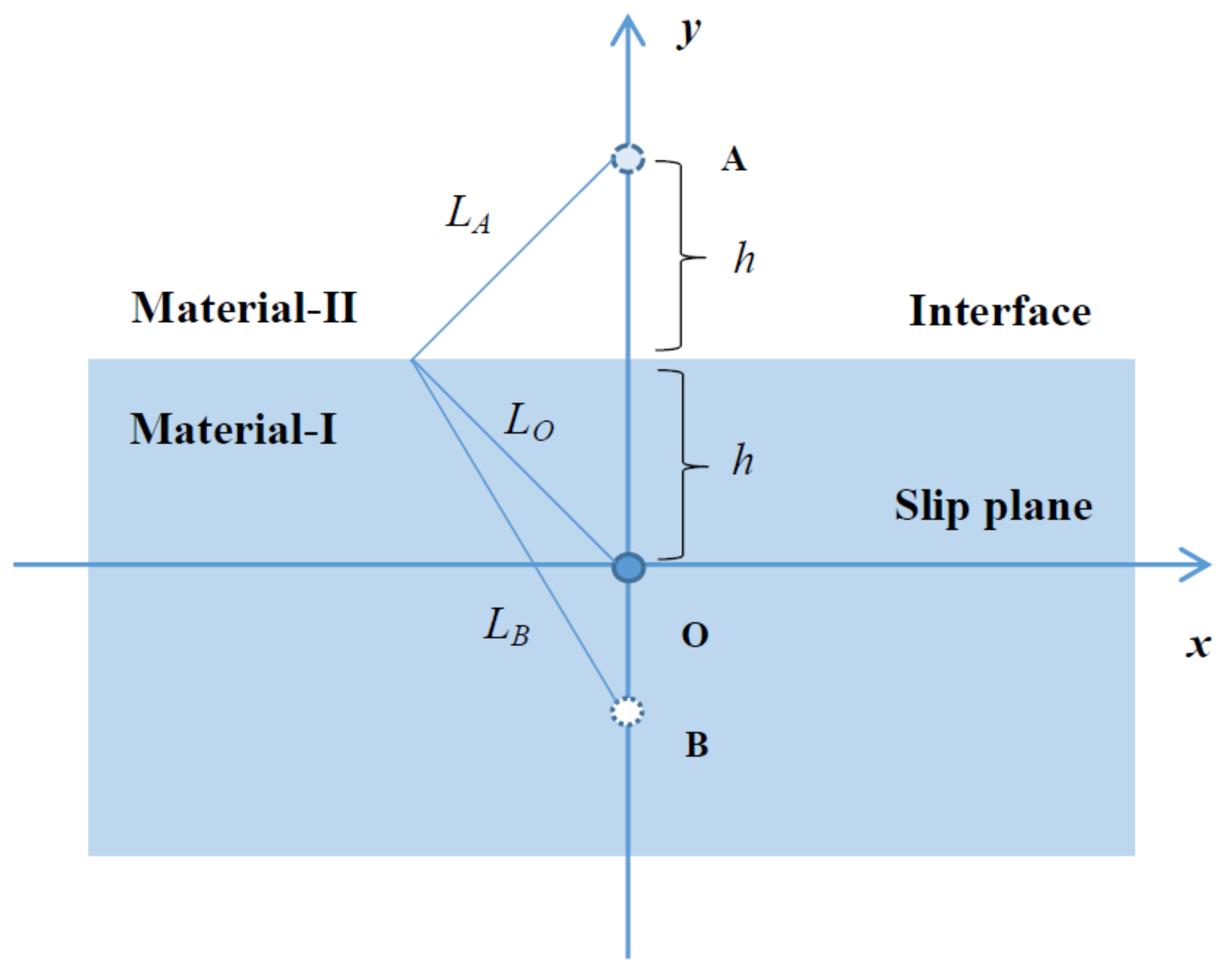
In order to take the interfacial effects on screw dislocations into account, an original right-handed screw dislocation parallel to the interface is represented by O (see
Figure 1). In a cartesian set of coordinates
, the original dislocation line is set to along the
z axis, the
plane is the slip plane, and
y is normal to the slip plane. The
plane is the interface of material-I and material-II. Material-I and material-II are placed at
and
. The shear moduli of material-I and material-II are
and
, respectively. Therefore,
h is the distance between interface and dislocation. Due to the equivalence of dislocations and point charges in elastic strain field and electrostatics, the image method is used to describe the interface effects on the dislocation elastic strain field. The interface effects on dislocations are represented by image dislocations. The image dislocation of O is at A. As we know, there is no strain field in material-II while the interface is not taken into account. The interface between material-I and material-II will introduce a strain field in the material. Accordingly, the interface effects on dislocation O is represented by image dislocation A . To account for finite strain in material-II, an additional image is placed at B to describe the interface effects. The dislocations O, A, and B have Burgers vectors of magnitudes
b,
, and
, respectively. According to the required boundary conditions that the displacements and stress must be continuous across the interface, the three dislocations must lie in the plane
, and in fact, the results verify that such an arrangement fulfills the boundary conditions. Additionally, in order for the displacements at the interface to vary in the same way with varying
x, it is necessary that
. The displacement and stress of the original screw dislocation are
It is important to elucidate that both image dislocations A and B are the images of the original screw dislocation O. In other words, the strain field in material-I is the same as that which would be produced by dislocation O and the image dislocation A, while the strain field in material-II is the same as that produced by dislocation B. Therefore, the displacement in material-I and material-II can be written as
and the stress in material-I and material-II can be written as
At the interface (
), the displacement and stress must be continuous; namely,
It is easy to yield
can be used to characterize the interface type. Dislocations are in the soft material for
(
) and the interface can be named as a rigid interface. When
(
), dislocations are in a rigid material and the interface can be named as a soft interface. When
, the interface is reduced to surface.
Now, the stress field on the slip plane (
) with the contribution of image dislocation can be written as
The above discussions are focused on the properties of dislocations in the continuum theory. A dislocation is a singular line in continuum theory, and can be displaced without any application of force. However, the influence of the lattice periodicity on dislocation properties should be taken into account. The P-N model is the first to determine the dislocation width and Peierls stress. In the P-N model, the crystal is set to be two semi-infinite crystals. The dislocation is produced from the nontrivial contact of two semi-infinite crystals. The dislocation core is assumed to spread, and the displacements are assumed to be produced by a continuous distribution of infinitesimal dislocations at every point
of Burgers vectors
. The total Burgers vector
. The infinitesimal dislocations combined with the stress field from elastic theory are used to derive equations for dislocations in bulk and misfit dislocations at the interface [
5,
14]. Accordingly, the governing equation for screw dislocation in heterostructure with the interfacial effects can easily yield
The restoring force
can be obtained from the gradient of GSF energy
with
the unstable stacking fault energy [
15].
is the maximum energy barrier for a moving dislocation.
Then, we have the restoring force
with the maximum restoring stress
.
It is interesting to discuss the dislocation equation for two limitations:
(i) When
(
), material-I and material-II are the same material. Both the interface and image dislocation do not exist. One obtains the classical P-N equation for an isolate screw dislocation in bulk:
(ii) When
(
), material-II is vacuum. The interface reduces to the surface of material-I. One obtains
This equation is the same as the previous dislocation equation obtained by Cheng et al. for a semi-infinite material with seldom free surface [
8].
3. Interfacial Effects on Dislocation Core and Peierls Stress
Foreman introduced an effective method (Foreman method) to solve the original P-N dislocation equation with nonsinusoidial restoring force [
16]. In this paper, we take the Foreman method to solve the screw dislocation with the interfacial effects. The typical Foreman solution for the screw dislocation is given as follows:
with
and
d the spacing distance of the planes parallel to the slip plane. The core structure parameter
is crucially determined by the maximum restoring force.
(
) reduces to the solution of the original P-N equation with
and the core width
. The core width is determined by
. However, the core width will be changed, while the unstable stacking fault energy and interface effects are taken into account. The Foreman method is a modification of the classical P-N solution for the classical P-N dislocation equation. The core structure parameter
is introduced into the classical P-N solution to obtain the Foreman solution, Equation (
19). It is clear that the classical P-N solution can be obtained from Equation (
19) if the core structure parameter
. Furthermore, the Foreman solution is introduced a parametric derivative form. This is helpful in solving the governing dislocation equation, Equation (
14).
Substituting the Foreman solution to the dislocation equation and letting
, the stress and displacement can be expressed as the parametric forms
with
and
in the range from 0 to
. The core structure parameter
can be determined by fitting Equation (
20) for the maximum restoring force. It is interesting to find that
when
and
.
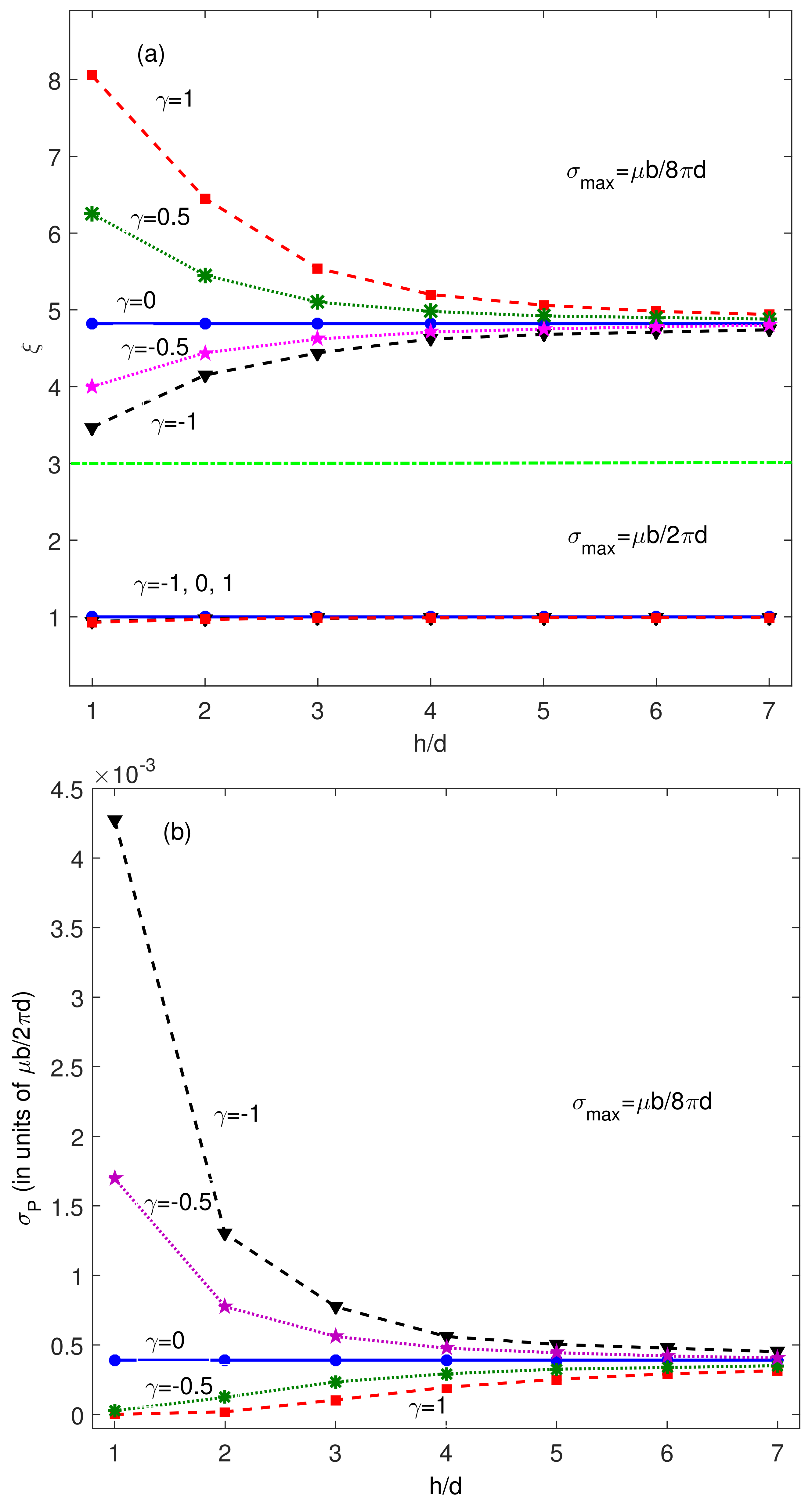
The variations of
with respect to distance
h for different interface types
are shown in
Figure 2. For comparison, the results of
and
are displayed. It worth noting that
decreases with
h for
and increases with
h for
when
. The larger the value of
h, the fewer influence the interface has on the dislocation core.
tends towards the results of
. The surface and interface effects on core structure become small for large
h. For the same
h,
leads to a larger
(wider dislocation core) than
. Namely, a rigid material will extend the dislocation core in a soft material. However, a soft material will compress the dislocation core in a rigid material. In other words, the image dislocation has the same (different) chirality with the original dislocation for
(
). This means that dislocations at the parallel slip planes with same chirality lead to a wide core, and different chirality lead to a narrow core. It should be kept in mind that the above discussions are based on a fixed maximum restoring force for different
h. The core structure parameter
is near the same for
for different
h and
(see
Figure 2).
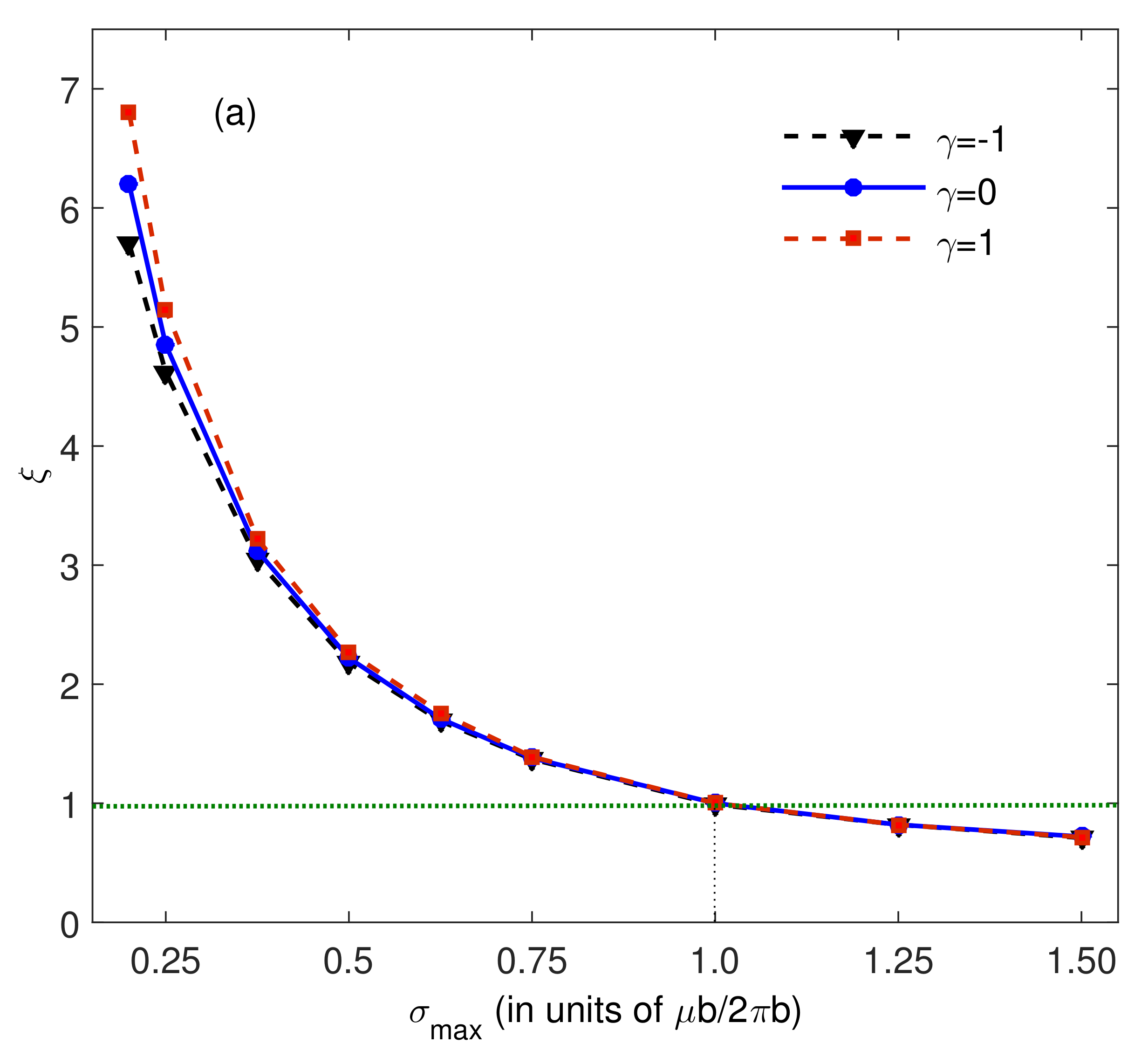
Figure 3a illustrates that the core structure parameter
decreases with increasing maximum restoring force
for
. It is clear that
and
for
and
, respectively. The difference between
and
is very small for higher
.
Generally, the mobility is controlled by the dislocation core width
and the unstable stacking fault energy
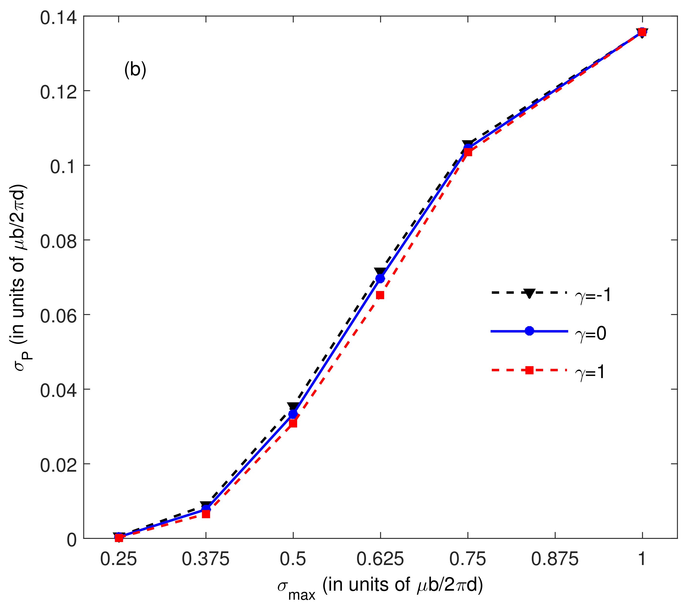
. The following formula can be used to predict the Peierls stress of dislocations:
Peierls stress for
and different interface types are illustrated in
Figure 2b. It is easy to see that Peierls stress can be enhanced by the interface for
(
), and reduced by the interface for
(
). The Peierls stress of screw dislocations in bulk material-I is
. We take
as an example. When
(
), the Peierls stress of screw dislocations is
. The Peierls stress is enhanced by the surface by about three times. When
(
), the Peierls stress of screw dislocations is
. The Peierls stress decreases with the increasing
. The Peierls stress of screw dislocations is
for
(
). The Peierls stress is reduced by the interface. Furthermore, the interface effect decreases with increasing
h and
for both
and
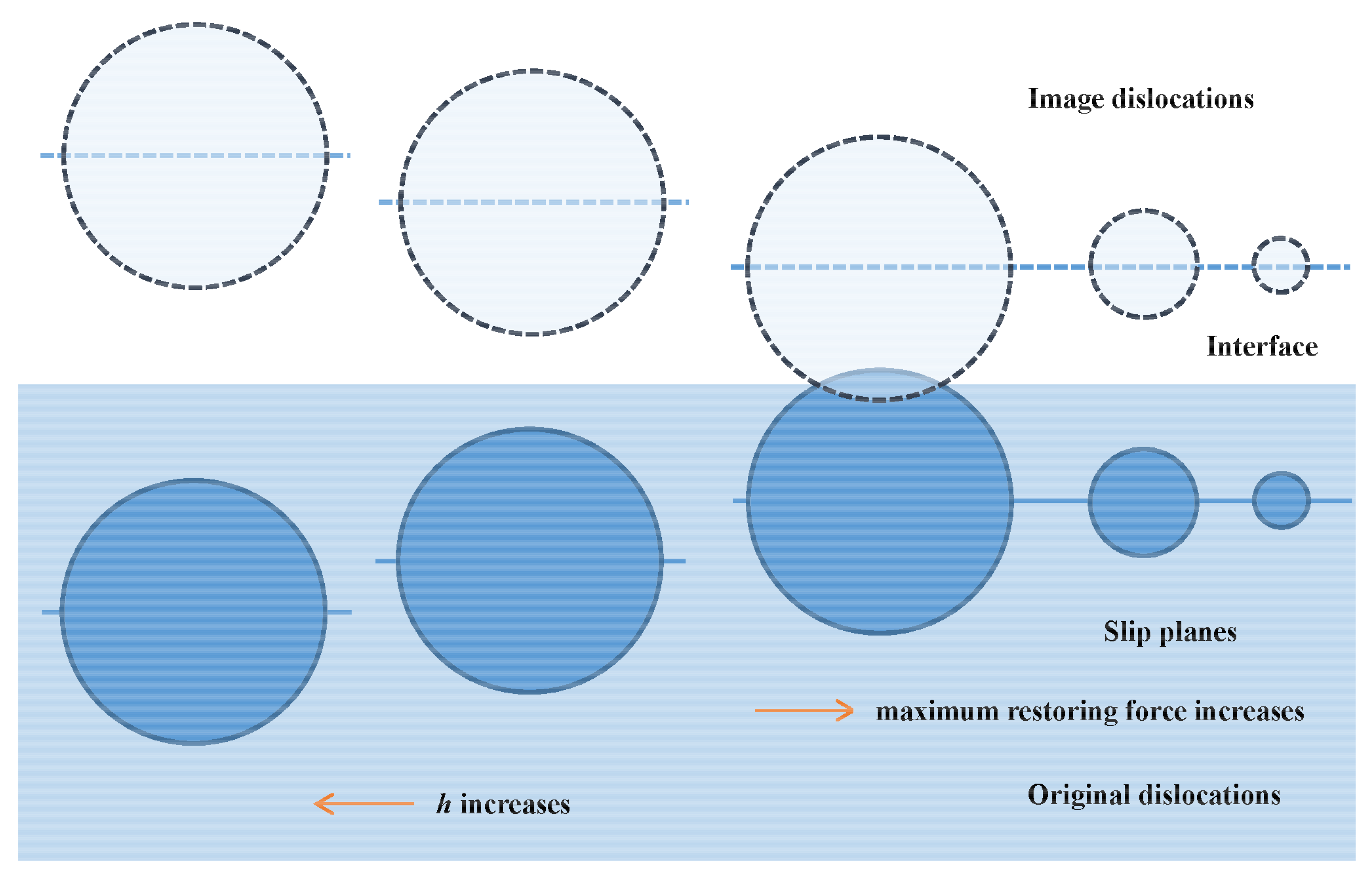
. This can be easily understood using
Figure 4. When
, the original core region will superpose with the image core region. The original dislocation core will be affected by the image core. The surface and interface effects cannot be ignored. The original core width decreases with increasing
. The distance between the original core region and the image core region become large, and the superposition of core regions becomes weak. The surface and interface effects on the original core are also reduced.
Figure 4 also shows that the superposition decreases with increasing
h.
Based on the above discussions, the conclusion can be made that the interface effects on the core width and Peierls stress are determined by the maximum restoring force
(the unstable stacking fault energy
), the distance to interface
h, and the interface type
. In order to elucidate their contributions, we take
as an example. The Peierls stress has the same order for
,
, and
. This is also true for
, although the Peierls stress has the biggest difference for
,
, and
. The Peierls stress also has the same order when
h in the range of
. However, the Peierls stress for
is 1000 times that for
(see
Figure 3). However, the Peierls stress for
is only 1.3 times of that for
. The Peierls stress for
is about 21 times that for
. Therefore, the interface effect on dislocation will be mainly controlled by the difference between the unstable stacking fault energy (the maximum restoring force) with and without interface. Furthermore, the interface effect is clearer when the unstable stacking energy in bulk material-I is smaller than
.
4. Screw Dislocations in Al/TiC Heterostructure
Generally, material-I and material-II have different lattice constants and shear moduli. The atoms near the interface adjust their position to reduce the elastic strain energy. These will change the unstable stacking fault energy in material-I and material-II. Compared to interfacial type (
) and distance (
h), the contributions of maximum restoring force (unstable stacking fault energy) needs to be discussed further. In order to investigate the direct effect of interface, we calculated the unstable stacking fault energy for Al/TiC heterostructures as a model interface using first principles methods. In order to make the paper easy to read, the detailed computation procedures are not listed (for detailed computation procedures, refer to [
17]). The interface is (100) plane, and the Burgers vector of screw dislocation is along
directions. The calculated lattice constants of Al and TiC are 4.04 and 4.33, respectively. The shear modulus is 26.0 GPa for Al and 164.5 GPa for TiC. According to the large difference in shear modulus between Al and TiC, we can use the coherent interface approximation. The softer Al is stretched to match the dimension of TiC. The axis normal to the interface is still the dimension of Al. If the difference of shear modulus is small, the material with larger constants will be stretched, and the other material will be compressed.
The unstable stacking fault energy is listed in
Table 1. The unstable stacking fault energy for bulk Al is 0.837 J/m
. When Al is stretched, the unstable stacking fault (USF) energy is 0.527 J/m
. The stretch reduces the USF energy by 0.31 J/m
. When the Al/TiC interface is formed, the unstable stacking fault energies in Al are 0.396, 0.540, 0.545, and 0.475 J/m
for distances
h = 1
d, 2
d, 3
d, and 4
d, respectively. The changes of energy between stretched Al and Al in the interface are 0.131, −0.013, −0.018, and 0.052 J/m
, respectively. The USF energy for bulk TiC is 3.582 J/m
. In the coherent interface approximation, TiC is not stretched. After the Al/TiC interface is formed, the unstable stacking fault energies in TiC are 3.650, 3.568, 3.576, and 3.582 J/m
. The energy differences are −0.068, 0.014, 0.006, and 0 J/m
. The interface formation can be postulated including two steps : (1) stretch soft Al, (2) form Al/TiC interface by TiC and stretched Al. The above calculation results show that step (1) provides the main contribution to the unstable stacking fault energy in comparison with step (2). Therefore, the interface effects on USF stacking are originated from the stretching of Al.
The change of energy between and stretched Al is larger than , 3d, and 4d. The calculated interfacial USF energy is 1.397 J/m, which is larger than bulk Al and stretched Al. This means that Al and C atoms at the interface have strong covalent bonding, resulting in a smaller unstable stacking fault energy for . However, the interfacial bonds have little impact on , 3d, and 4d, due to the locality of stacking fault energy.
For screw dislocations in Al and TiC, the interface types (
) are
(rigid interface) and
(soft interface), respectively. The core width and Peierls stress is listed in
Table 1. The Peierls stress of screw dislocations in interface-Al is smaller than that in bulk Al due to the stretching when forming the Al/TiC interface. The lattice constants are unaltered when forming the Al/TiC interface due to large shear modulus. The Peierls stress is nearly the same in bulk TiC and interface-TiC.


