Article

Thermostability, Photoluminescence, and Electrical Properties of Reduced Graphene Oxide–Carbon Nanotube Hybrid Materials

1
Nanjing National Laboratory of Microstructures, Physics Department, Nanjing University, Nanjing 210093, China
2
College of Physics and Technology, Guangxi Normal University, Guilin 541004, China
3
Key Laboratory for Organic Electronics and Information Displays and Institute of Advanced Materials, Nanjing University of Posts & Telecommunications, Nanjing 210046, China
*
Author to whom correspondence should be addressed.
Crystals 2013, 3(1), 28-37; https://doi.org/10.3390/cryst3010028
Submission received: 8 November 2012 / Revised: 27 December 2012 / Accepted: 9 January 2013 / Published: 21 January 2013
(This article belongs to the Special Issue Graphenes)

Abstract

:
Reduced graphene oxide–carbon nanotube (RGO–CNT) hybrid materials were prepared by a simple catalyst-free route. The thermostability, photoluminescence (PL) and electrical properties of RGO–CNTs were investigated systematically. The results revealed that compared to RGO, RGO–CNTs showed multicolor PL, and higher thermostability and conductivity. The RGO–CNTs therefore have important potential applications in the fields of photonic and electrical devices.

1. Introduction

The need for improved thermal interface materials (TIMs) in modern electronics and optoelectronics stimulated interest in carbon materials as fillers for TIMs. Carbon materials that were studied as fillers include carbon nanotubes (CNTs), graphite nanoplatelets, graphene oxide nanoparticles and graphene flakes derived by chemical processes [1]. For example, the graphene–multilayer graphene nanocomposites [2] or the hybrid graphene–metal particle [3] can be used for TIMs with the strongly enhanced thermal conductivity. Graphene is essentially a CNT cut along its axis and unrolled to lie flat [4]. Notably, CNTs have superior mechanical properties but must be dispersed uniformly and form a network to achieve sufficient percolation for electrical conductivity. Graphene has remarkably high electron mobility but causes the problem of its restacking property [5]. To efficiently establish synergistic effects between these two different graphitic nanostructures, much attempt has been made to explore graphene and CNT hybrid materials (G–CNTs) in recent years [6,7,8,9,10,11]. Owning to its unique physical and chemical properties, G–CNTs have been widely used in various fields such as high-performance transparent conductors [4], supercapacitors [12,13,14], solar cells [15], fuel cells [16], and electrode [17], etc. In addition, the optical properties of G–CNTs also aroused much attention. For example, Kim et al. [18] fabricated G–CNT transparent 2-dimensional optical array and researched its holographic property.
Up to now, G–CNTs were commonly synthesized by chemical vapor deposition with the assistance of the metallic catalysts. For example, Dong et al. [19] synthesized highly conductive G–CNTs using copper as catalyst under ethanol. Kim et al. [18] fabricated G–CNTs using Al and Fe as catalysts under Ar, H2 and C2H2 gas atmosphere. Very recently, we synthesized reduced graphene oxide–CNT hybrid materials (RGO–CNTs) by a facile and catalyst-free route, and found that the weight ratio of CNTs to RGO can be adjusted in a relatively wide range of 0.33 to 7.039 by regulating the annealing temperature [20]. Herein, we reported the thermostability, photoluminescence (PL) and electrical properties of RGO–CNTs obtained. Interestingly, compared to RGO, RGO–CNTs possess obvious multicolor PL, and higher thermostability and conductivity.

2. Experimental Section

2.1. Preparation

As reported previously, RGO–CNTs were fabricated by a catalyst-free route [20]. Briefly, the graphene oxide (GO) was synthesized by chemical exfoliation of 5 g natural flake graphite powder (500 mesh) [21]. Then GO powder was put in a quartz boat, and was placed inside a quartz tube. With the quartz tube located in a horizontal reaction tube furnace (equipped with temperature and gas-flow control), GO was annealed in a flowing Ar/acetylene (50 sccm/2.5 sccm) gas mixture at a target temperature using a 40 °C min−1 heating rate for 1 h at atmospheric pressure. After cooling the tube furnace to room temperature (RT), the RGO–CNT samples (RGO–CNT-550, RGO–CNT-650, RGO–CNT-750, and RGO–CNT-900, numbers denoting the annealing temperature) could be obtained. As a comparison, GO was annealed in Ar by similar annealing procedure in acetylene, and RGO samples (RGO-550, RGO-650, RGO-750, and RGO-900, numbers denoting the annealing temperature) also can be obtained. In order to avoid metal contamination, all the experiment processes were performed with special care. Not one metal had any contact with the samples during the experiments.

2.2. Characterization

The morphologies of the samples were performed by field emission scanning electron microscopy (FE-SEM) (FEI Sirion200). X-ray photoemission spectroscopy (XPS) measurements were performed on a Thermo Fisher Scientific with Al Kα radiation. The thermogravimetric analysis (TGA) was measured with a STA 449C-Thermal Star 300 using a 1 °C/min heating rate under argon flow (20 mL/min). The PL and PL excitation (PLE) spectra of RGO and RGO–CNTs were recorded at RT on a Shimadzu RF-5301PC fluorescence spectrophotometer using a Xe lamp as the light source. For PL spectra investigation, 1.5 mg of powder samples was ultrasonically dispersed in 50 mL of ethanol solution for 1 h. After that, the solution was used. The indium tin oxide (ITO) substrates were washed by ultrasonication with acetone solution, ethanol solution, and deionized water for 10 min, respectively. Then the ITO substrates were dried under an ultrapure nitrogen stream, and were treated at 80 °C for 2 h. Thereafter, the substrates were irradiated with ultraviolet (UV) light for 30 min. For the preparation of RGO and RGO–CNT films, 1.5 mg of RGO or RGO–CNTs was dispersed in ethanol and deposited on the substrates by the spin-coating method. After that, the Al electrodes with the thickness of ca. 100 nm were deposited on the top of the surface of films by thermal deposition system. Finally, a diode device can be obtained, the cathode and anode of which are Al and ITO, respectively. The I–V curves of RGO and RGO–CNT films were measured by a semiconductor parameter analyzer (Agilent B1500) under ambient conditions. A continuous voltage was applied across the cathode and anode. The corresponding current value can be obtained through the semiconductor parameter analyzer.

3. Results and Discussion

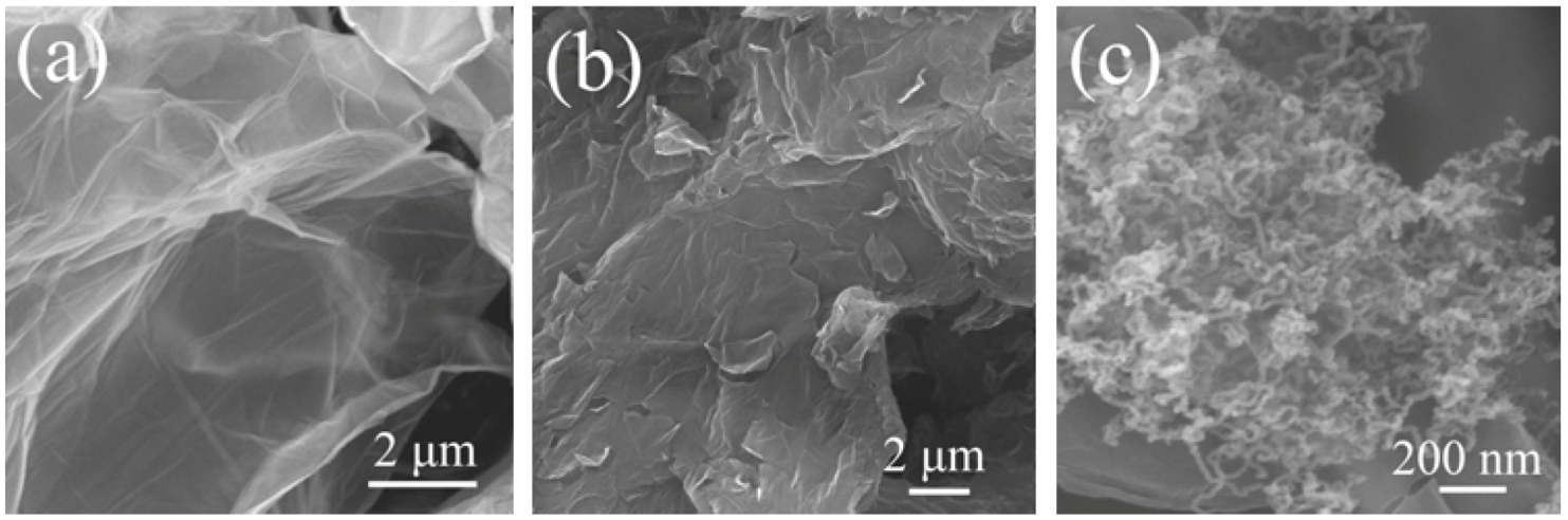
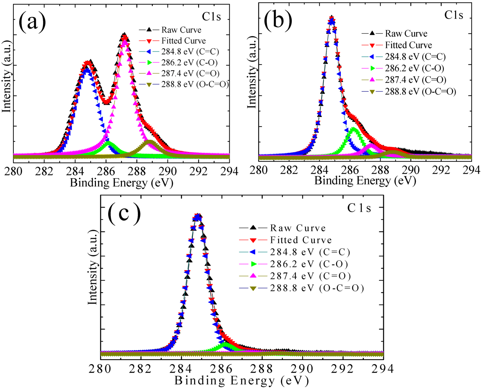
3.1. Microstructures of the Samples

Shown in Figure 1a,b are the typical FE-SEM images of GO and RGO-650. One can clearly see that GO demonstrates an ultrathin flexible sheet-like structure, and RGO-650 has more corrugations than GO. Figure 1c depicts the morphology of RGO–CNT-650. It reveals a considerable growth of CNTs on or between the RGO layers, and the CNTs are relatively uniform with a diameter of ca. 10–30 nm. Moreover, one can find that the CNTs are horizontally and randomly stacked between or on the RGO layers. It may be due to the restriction of full length extension of the flexible CNTs in the space within the graphene layers, which act as a supporting holder to mediate the organization of the CNTs [6].
Figure 1. Field emission scanning electron microscopy (FE-SEM) images of (a) graphene oxide (GO); (b) Reduced graphene oxide (RGO)-650; and (c) Reduced graphene oxide–carbon nanotube (RGO–CNT)-650.
Crystals 03 00028 g001
To detect the C and O content and the bonding environment of the samples, XPS measurements were carried out. Figure 2a shows the fine-scanned XPS C 1s peaks of GO, which was fitted by four components that correspond to carbon atoms in different functional groups. The main peak at 284.8 eV is due to graphitic sp2 carbon atoms (C=C), and the other peaks at 286.2 eV, 287.4 eV, and 288.8 eV correspond to hydroxy (C–O bond), carbonyl (C=O), and carboxyl (O–C=O), respectively [22,23]. The C/O ratio of GO is 2.8:1. In contrast, the peak intensities of the oxygen functional groups of RGO-650 decreased significantly (Figure 2b), and the C/O ratio is 9.4:1. Notably, it is found that (i) the peak intensities of the oxygen functional groups of RGO–CNT-650 decreased more sharply than that of RGO-650 (Figure 2c); and (ii) the C/O ratio of the RGO–CNT-650 reaches high up to 22.6:1. The reason for the high C/O ratio of the RGO–CNT-650 may be (i) the more effective deoxygenation of GO annealed in acetylene than in Ar; and (ii) high-yield CNTs grew on the surface of RGO. As reported previously, the weight ratio of CNTs to RGO of RGO–CNT-550, RGO–CNT-650, RGO–CNT-750, and RGO–CNT-900 can be calculated, which are 1.006, 3.952, 7.039, and 6.247, respectively [20].
Figure 2. X-ray photoemission spectroscopy (XPS) spectra of (a) GO; (b) RGO-650; and (c) RGO–CNT-650.
Crystals 03 00028 g002

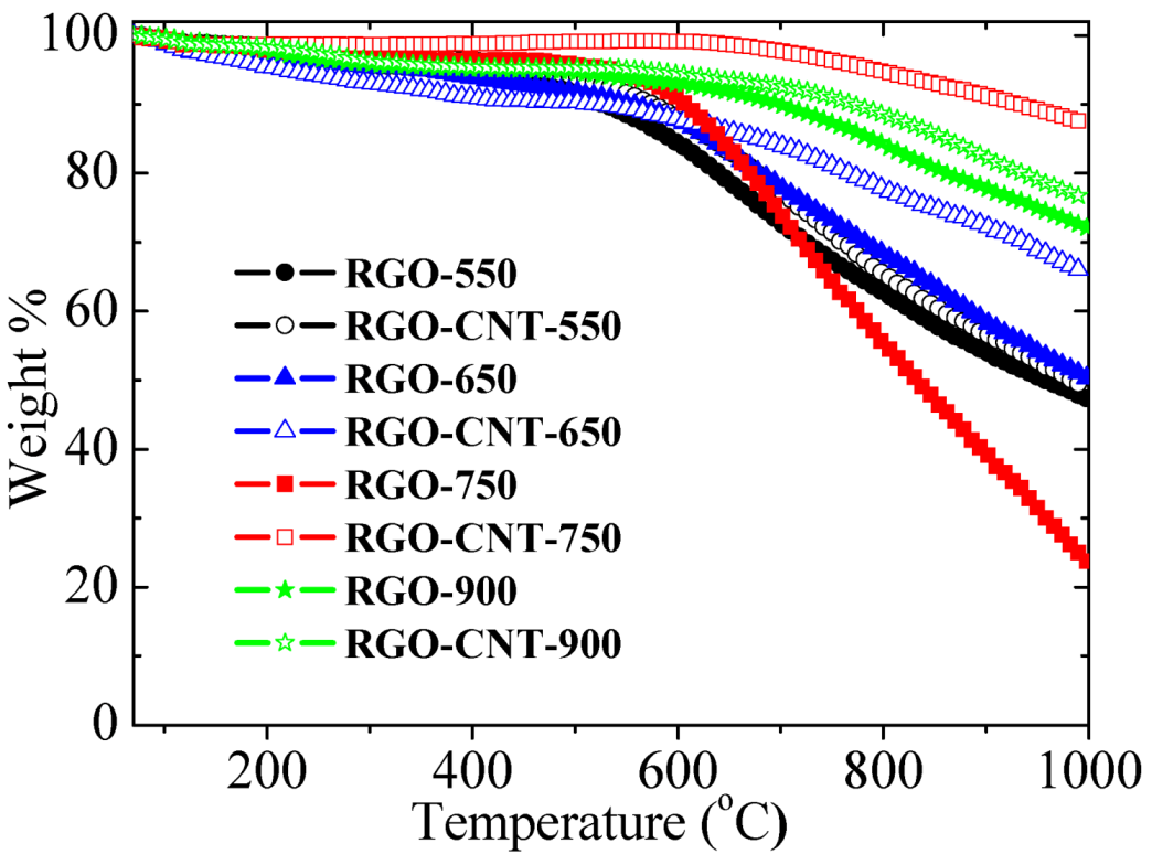
3.2. Thermostability

As proposed by Balandin, graphene and CNTs possess excellent thermal properties. Thermal conductivity of graphene and CNTs can reach up to above 2000 W mK−1 and to ~3000–3500 W mK−1 at room temperature, respectively. An especially important characteristic for TIM applications of graphene is its high temperature stability, which was verified up to 2600 K [1]. TGA graphs show weight profiles of RGO and RGO–CNTs as variations of temperature (Figure 3). Clearly, all the RGO–CNTs show higher thermostability than the corresponding RGO samples. For example, RGO–CNT-750 shows much higher thermostability than RGO-750. This may be attributed to (i) more effective reduction of GO that can be obtained by acetylene than by Ar; and (ii) the massive high-thermostability CNTs that are grown. It is generally known that naturally occurring carbon materials are made up of two stable isotopes of 12C (~99%) and 13C (1%) [24]. The change in isotope composition modifies dynamic properties of crystal lattices and affects their thermal conductivity [24,25]. The dynamic properties of the RGO may be changed by massive-growth CNTs and thus the thermal properties of the RGO may be obviously changed. Moreover, with the rise in the annealing temperature, the thermostability of RGO–CNTs increases first then subsequently decreases, and RGO–CNT-750 possesses the highest thermostability. However, with the further increasing of the annealing temperature, it shows a clear decrease. As reported previously, above 550 °C, the weight ratio of CNTs to RGO in RGO–CNTs shows a fast increase, and it can reach a high maximum of ca. 7.039 at 750 °C [20]. Evidently, the changing tendency of the thermostability of RGO–CNTs is in good agreement with the change of the content of CNTs in the RGO–CNTs. In other words, a higher content of CNTs can contribute to a higher thermostability for RGO–CNTs. Namely, one can change the thermal properties of the RGO–CNTs by tuning the content of CNTs in the RGO–CNTs for special application.
Figure 3. Thermogravimetric analysis (TGA) curves of RGO and RGO–CNTs.
Crystals 03 00028 g003

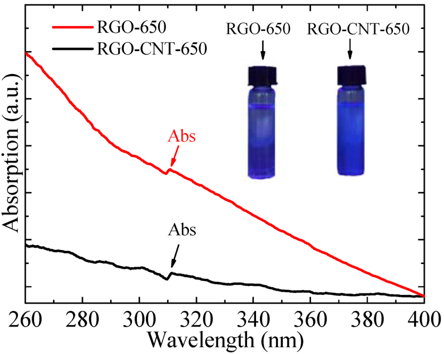
3.3. UV–vis Absorption Spectra
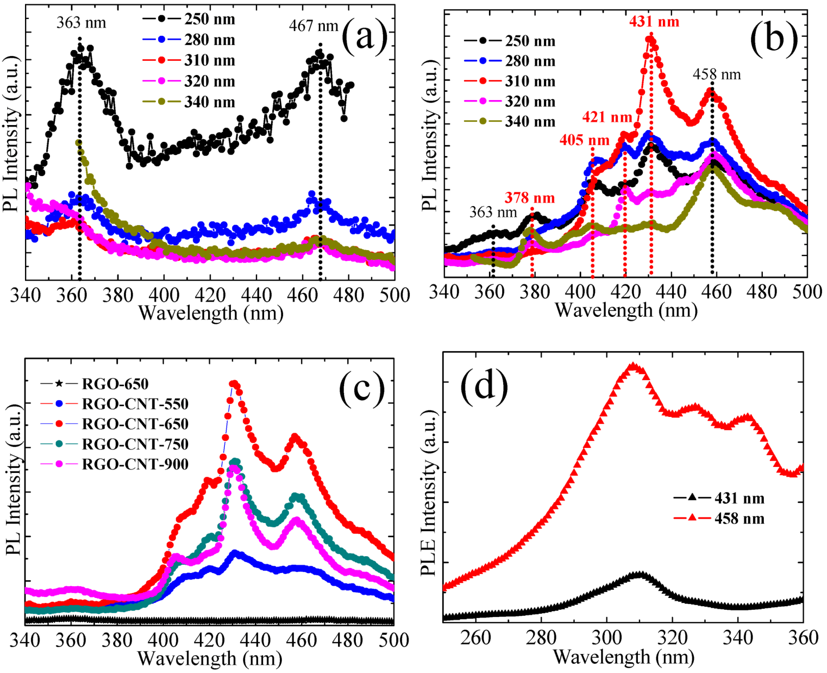
Shown in Figure 4 are the UV–vis absorption spectra of RGO-650 and RGO–CNT-650. Both of them show an obvious absorption peak centered at ca. 310 nm. Under irradiation by a 365 nm UV light, one can clearly find that both of them show blue luminescence; however, RGO–CNT-650 emits stronger luminescence than RGO-650. It may attribute to the contribution of CNTs in RGO–CNTs. Similarly, the UV-Vis absorption spectra of other RGO and RGO–CNT samples were measured, and all of them show a similar absorption peak centered at ca. 310 nm (not shown).
Figure 4. UV–vis absorption spectra of RGO-650 and RGO–CNT-650. Inset: Photograph of RGO-650 and RGO–CNT-650 ethanol solution taken under 365 nm UV light, respectively.
Crystals 03 00028 g004

3.4. PL Spectra

To explore the optical properties of RGO and RGO–CNTs, a detailed PL study was carried out at RT. Figure 5a shows the PL spectra of RGO-650 with different excitation wavelengths from 250 to 340 nm. It is found that there are two clear emission peaks, one is in the UV region at ca. 363 nm and another is in the blue region at ca. 467 nm. With the excitation wavelength increasing from 250 to 340 nm, the intensity of the two PL peaks decreases significantly. Shown in Figure 5b are the PL spectra of RGO-650 with different excitation wavelengths from 250 to 340 nm. Interestingly, compared to RGO-650, RGO–CNT-650 has four extra PL peaks of 378, 405, 421, and 431 nm, indicating that RGO–CNT-650 has multicolor PL. Thus, one can make a reasonable assumption that the four strong PL emission should originate from CNTs in RGO–CNTs. Notably, RGO–CNT-650 exhibits a relative wide range of emission light wavelength, which can cover from UV (363 and 380 nm) to purple (405, 421, and 431 nm), and to blue (458 nm). Apparently, the energy level of RGO–CNT-650 is greatly different from that of RGO-650. It may be due to the contribution of CNTs in RGO–CNTs. As pointed out by Dukovic et al. [26], each PL peak of CNTs corresponds to an emission from a particular nanotube structure, and especially depends on the diameter of the CNT. Furthermore, with the increase of the excitation wavelength from 250 to 340 nm, one can see that (i) RGO–CNT-650 exhibits an excitation-independent PL behavior, and the peak positions remain almost unchanged at ca. 363, 378, 405, 421, 431, and 458 nm, respectively; (ii) the intensity of the PL peaks rise first, before decreasing with the increasing excitation wavelength, which reaches a maximum at the excitation wavelength of 310 nm, and thus differing greatly from the case of RGO-650.
Figure 5c shows the PL spectra of RGO-650 and RGO–CNT samples excited at 310 nm. It is found that all the PL intensity of the RGO–CNT samples is much higher than that of RGO-650. Moreover, one can see that with the increase of the annealing temperature: (i) The PL intensity of RGO–CNT samples increases, and reaches its maximum at 650 °C; and (ii) above 650 °C, the PL intensity decreases. As mentioned above, RGO–CNT-750 has the highest content of CNTs among these samples, but its PL intensity is not the strongest. Therefore, an appropriate content of CNTs is useful to the PL. Therefore, by selecting an appropriate annealing temperature, one can change the content of CNTs and thus tune the PL properties of RGO–CNTs for specific applications. Shown in Figure 5d is the PLE spectra of RGO–CNT-650 with excitation at 431 and 458 nm. One sharp peak at ca. 310 nm recorded with the strongest luminescence can be clearly seen.
Figure 5. Photoluminescence (PL) spectra at different excitation wavelengths of (a) RGO-650; (b) RGO–CNT-650; (c) PL spectra of RGO-650 and RGO–CNT samples at excitation wavelength of 310 nm; (d) Photoluminescence excitation (PLE) spectra of RGO–CNT-650 with the detection wavelengths of 431 nm and 458 nm.
Crystals 03 00028 g005

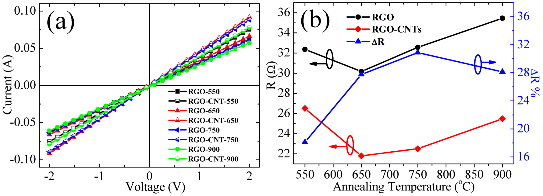
3.5. Electrical Properties of the Samples

The electrical characteristics of RGO and RGO–CNT films were measured in an air environment. As can be seen from Figure 6a, the I−V curves of RGO and RGO–CNT films show obviously ohmic-like characteristics, rather than the Schottky diode feature [27]. As proposed by Patole et al., because of the formation of an extended conjugation network within the CNTs bridging the gaps between the graphene sheets, the conductivity in the hybrid materials can show great improvement [28]. Based on the I−V curves (shown in Figure 6a), one can calculate the corresponding R of RGO and RGO–CNT films. Shown in Figure 6b is the dependence of R of RGO and RGO–CNT films on annealing temperature. In the case of RGO films, with the increasing of the annealing temperature, one can see that the R of RGO films decreases first and then increases, and reaches the minimum and maximum at 650 °C and 900 °C, respectively. The reason may be that a too high an annealing temperature may introduce a high concentration of defect in RGO. Similarly, one can find that the dependence of R on the annealing temperature of RGO–CNT films is similar to the case of RGO films. A clear difference from the case of RGO films is that the R of RGO–CNT films reach the minimum and the maximum at 650 °C and 550 °C, respectively. Moreover, one can find that the R of all RGO–CNT films is lower than that of the corresponding RGO films. It may be ascribed to the inclusion of CNTs in RGO–CNTs.
To further explore the role of CNTs in the conductivity of RGO–CNTs, the reduction percent ∆R was calculated (shown in Figure 6b). Where ∆R = (RRGORRGO–CNT)/RRGO (×100%), the RRGO is R of RGO films and RRGO–CNT is R of RGO–CNT films. Clearly, above 550 °C, the ∆R shows a fast increase, and reaches up to ca. 30.88% at 750 °C. However, with the further increase of the annealing temperature, it shows a decrease. Approximately, by regulating the annealing temperature, the ∆R can be adjusted in a relatively wide range of 18.09% to 30.88%. Apparently, the content of CNTs in RGO–CNTs has an obvious effect on the conductivity, and an appropriate content of CNTs is useful to obtain RGO–CNT films with high conductivity. It is different from the results reported, wherein a higher content of CNTs in G–CNTs can lead to a higher conductivity [19,29]. It implies that the contribution of CNTs is effective, but complicated.
Figure 6. (a) I–V curves of RGO and RGO–CNT films; (b) The dependences of the resistance R of RGO films (showing with black symbols) and RGO–CNT films (showing with red symbols) on annealing temperature.
Crystals 03 00028 g006

4. Conclusions

In conclusion, RGO–CNTs were prepared by a simple catalyst-free route. It is found that RGO–CNTs have high thermostability, which is proportionate to the content of CNTs. RGO–CNTs showed excitation-independent multicolor PL, which may be attributed to the fact that CNTs contribute the formation of the unique energy level. Furthermore, RGO–CNT films have high conductivity, which can be tuned by changing the annealing temperature. All the results suggest that the RGO–CNTs can find potential applications in the fields of photonic and electrical devices.

Acknowledgments

This work was financially supported by the State Key Program for Basic Research (Grant No. 2012CB932304 and 2010CB923402), and NSFC (Grant No. 51072079), China.

References

  1. Balandin, A.A. Thermal properties of graphene and nanostructured carbon materials. Nat. Mater. 2011, 10, 569–581. [Google Scholar] [CrossRef]
  2. Shahil, K.M.F.; Balandin, A.A. Graphene–multilayer graphene nanocomposites as highly efficient thermal interface materials. Nano Lett. 2012, 12, 861–867. [Google Scholar] [CrossRef]
  3. Goyal, V.; Balandin, A.A. Thermal properties of the hybrid graphene–metal nano-micro-composites: Applications in thermal interface materials. Nano Lett. 2012, 100, 073113:1–073113:4. [Google Scholar]
  4. Tung, V.C.; Chen, L.M.; Allen, M.J.; Wassei, J.K.; Nelson, K.; Kaner, R.B.; Yang, Y. Low-temperature solution processing of graphene–carbon nanotube hybrid materials for high-performance transparent conductors. Nano Lett. 2009, 9, 1949–1955. [Google Scholar] [CrossRef]
  5. Geim, A.K.; Novoselov, K.S. The rise of graphene. Nat. Mater. 2007, 6, 183–191. [Google Scholar] [CrossRef]
  6. Su, Q.; Liang, Y.; Feng, X.; Mullen, K. Towards free-standing graphene/carbon nanotube composite films via acetylene-assisted thermolysis of organocobalt functionalized graphene sheets. Chem. Commun. 2010, 46, 8279–8281. [Google Scholar] [CrossRef]
  7. Coleman, J.N.; Khan, U.; Gunko, Y.K. Mechanical reinforcement of polymers using carbon nanotubes. Adv. Mater. 2006, 18, 689–706. [Google Scholar] [CrossRef]
  8. Harris, P.J.F. Carbon nanotube composites. Int. Mater. Rev. 2004, 49, 31–43. [Google Scholar] [CrossRef]
  9. Stankovich, S.; Dikin, D.A.; Dommett, G.H.B.; Kohlhaas, K.M.; Zimney, E.J.; Stach, E.A.; Piner, R.D.; Nguyen, S.T.; Ruoff, R.S. Graphene-based composite materials. Nature 2006, 442, 282–286. [Google Scholar] [CrossRef]
  10. Liang, Y.; Wu, D.; Feng, X.; Müllen, K. Dispersion of graphene sheets in organic solvent supported by ionic interactions. Adv. Mater. 2009, 21, 1679–1683. [Google Scholar] [CrossRef]
  11. Thostenson, E.T.; Ren, Z.; Chou, T.W. Advances in the science and technology of carbon nanotubes and their composites: A review. Compos. Sci. Technol. 2001, 61, 1899–1912. [Google Scholar] [CrossRef]
  12. Yu, D.; Dai, L. Self-assembled graphene/carbon nanotube hybrid films for supercapacitors. J. Phys. Chem. Lett. 2010, 1, 467–470. [Google Scholar] [CrossRef]
  13. Fan, Z.; Yan, J.; Zhi, L.; Zhang, Q.; Wei, T.; Feng, J.; Zhang, M.; Qian, W.; Wei, F. A three-dimensional carbon nanotube/graphene sandwich and its application as electrode in supercapacitors. Adv. Mater. 2010, 22, 3723–3728. [Google Scholar] [CrossRef]
  14. Du, F.; Yu, D.S.; Dai, L.M.; Ganguli, S.; Varshney, V.; Roy, A.K. Preparation of tunable 3D pillared carbon nanotube–graphene networks for high-performance capacitance. Chem. Mater. 2011, 23, 4810–4816. [Google Scholar] [CrossRef]
  15. Ahmad, I.; Khan, U.; Gunko, Y.K. Graphene, carbon nanotube and ionic liquid mixtures: Towards new quasi-solid state electrolytes for dye sensitised solar cells. J. Mater. Chem. 2011, 21, 16990–16996. [Google Scholar] [CrossRef]
  16. Jyothirmayee Aravind, S.S.; Imran Jafri, R.; Rajalakshmi, N.; Ramaprabhu, S. Solar exfoliated graphene–carbon nanotube hybrid nano composites as efficient catalyst supports for proton exchange membrane fuel cells. J. Mater. Chem. 2011, 21, 18199–18204. [Google Scholar] [CrossRef]
  17. Kim, Y.K.; Min, D.H. Durable large-area thin films of graphene/carbon nanotube double layers as a transparent electrode. Langmuir 2009, 25, 11302–11306. [Google Scholar] [CrossRef]
  18. Kim, U.J.; Lee, I.H.; Bae, J.J.; Lee, S.; Han, G.H.; Chae, S.J.; Gunes, F.; Choi, J.H.; Baik, C.W.; Kim, S.I.; Kim, J.M.; Lee, Y.H. Graphene/carbon nanotube hybrid-based transparent 2D optical array. Adv. Mater. 2011, 23, 3809–3814. [Google Scholar]
  19. Dong, X.; Li, B.; Wei, A.; Cao, X.; Chan-Park, M.B.; Zhang, H.; Li, L.J.; Huang, W.; Chen, P. One-step growth of graphene–carbon nanotube hybrid materials by chemical vapor deposition. Carbon 2011, 49, 2944–2949. [Google Scholar] [CrossRef]
  20. Liu, F.C.; Li, M.; Feng, Q.; Tang, N.J.; Zhong, W.; Huang, W.; Du, Y.W. Catalyst-free synthesis of reduced graphene oxide–carbon nanotube hybrid materials by acetylene-assisted annealing graphene oxide. Appl. Phys. Lett. 2012, 101, 123107:1–123107:3. [Google Scholar]
  21. Wu, Z.S.; Ren, W.; Gao, L.; Liu, B.; Jiang, C.; Cheng, H.M. Synthesis of high-quality graphene with a pre-determined number of layers. Carbon 2009, 47, 493–499. [Google Scholar] [CrossRef]
  22. Pei, S.; Cheng, H.M. The reduction of graphene oxide. Carbon 2012, 50, 3210–3228. [Google Scholar] [CrossRef]
  23. Paredes, J.I.; Villar-Rodil, S.; Martínez-Alonso, A.; Tascón, J.M.D. Graphene oxide dispersions in organic solvents. Langmuir 2008, 24, 10560–10564. [Google Scholar] [CrossRef]
  24. Nika, D.L.; Balandin, A.A. Two-dimensional phonon transport in graphene. J. Phys. Condens. Matter. 2012, 24. [Google Scholar] [CrossRef]
  25. Chen, S.S.; Wu, Q.Z.; Mishra, C.; Kang, J.Y.; Zhang, H.J.; Cho, K.; Cai, W.W.; Balandin, A.A.; Ruoff, R.S. Thermal conductivity of isotopically modified graphene. Nat. Mater. 2012, 11, 203–207. [Google Scholar] [CrossRef]
  26. Dukovic, G.; White, B.E.; Zhou, Z.; Wang, F.; Jockusch, S.; Steigerwald, M.L.; Heinz, T.F.; Friesner, R.A.; Turro, N.J.; Brus, L.E. Reversible surface oxidation and efficient luminescence quenching in semiconductor single-wall carbon nanotubes. J. Am. Chem. Soc. 2004, 126, 15269–15276. [Google Scholar]
  27. Shafiei, M.; Spizzirri, P.G.; Arsat, R.; Yu, J.; du Plessis, J.; Dubin, S.; Kaner, R.B.; Kalantar-Zadeh, K.; Wlodarski, W. Platinum/graphene nanosheet/SiC contacts and their application for hydrogen gas sensing. J. Phys. Chem. C 2010, 114, 13796–13801. [Google Scholar]
  28. Patole, A.S.; Patole, S.P.; Jung, S.Y.; Yoo, J.B.; An, J.H.; Kim, T.H. Self assembled graphene/carbon nanotube/polystyrene hybrid nanocomposite by in situ microemulsion polymerization. Eur. Polym. J. 2012, 48, 252–259. [Google Scholar] [CrossRef]
  29. Bittolo Bon, S.; Valentini, L.; Kenny, J.M.; Peponi, L.; Verdejo, R.; Lopez-Manchado, M.A. Electrodeposition of transparent and conducting graphene/carbon nanotube thin films. Phys. Status Solidi A 2010, 207, 2461–2466. [Google Scholar] [CrossRef]

