
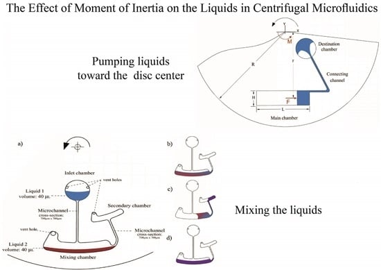
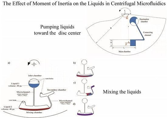
The Effect of Moment of Inertia on the Liquids in Centrifugal Microfluidics

Abstract
:
1. Introduction
2. Methodology
2.1. Concept
2.2. Experimental Setup and Fabrication
3. Results and Discussions
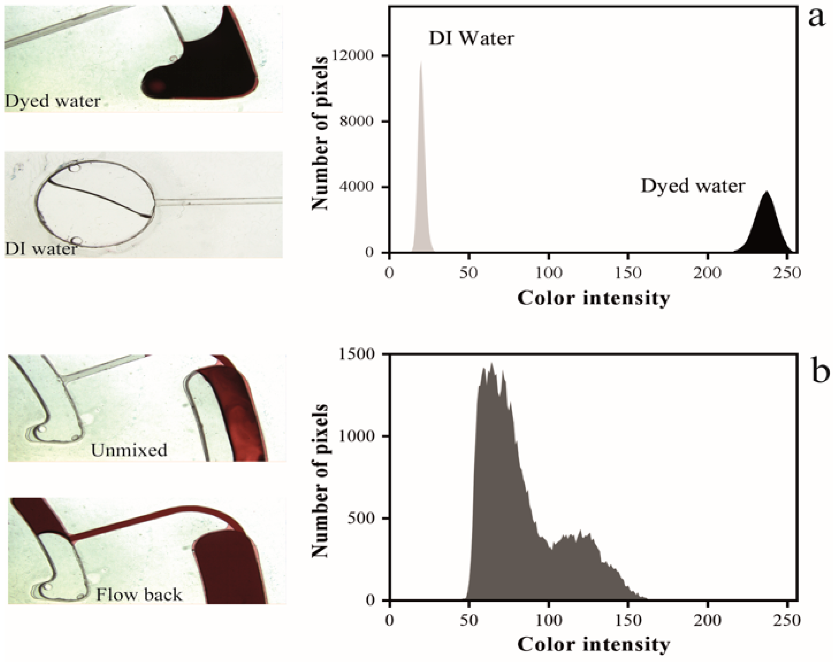
3.1. Characterization
3.2. Exprimental Validation
4. Application
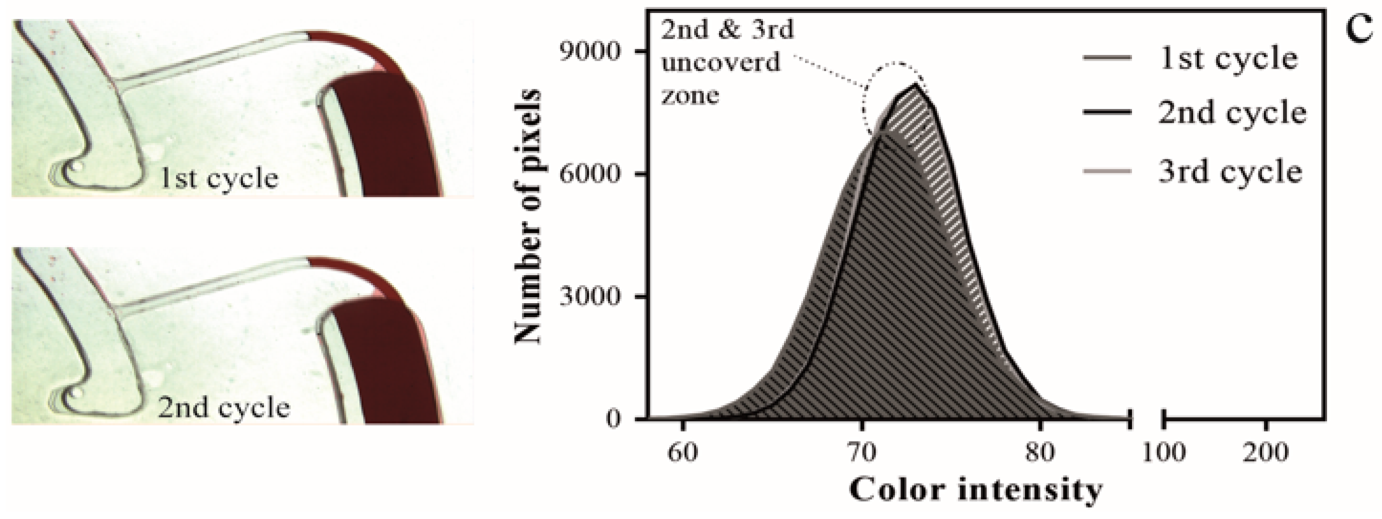
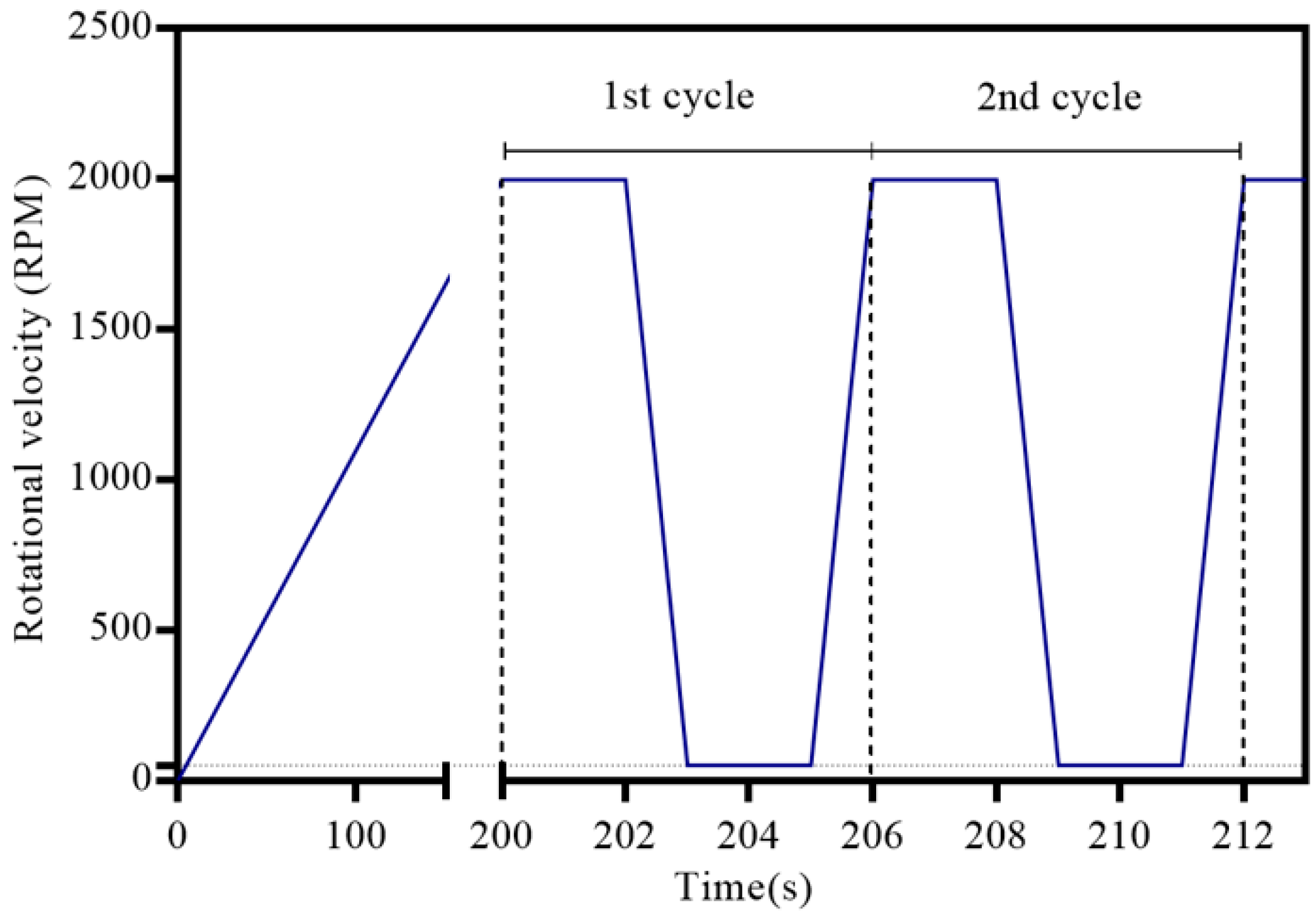
4.1. Mixing Concept
4.2. Mixing Design
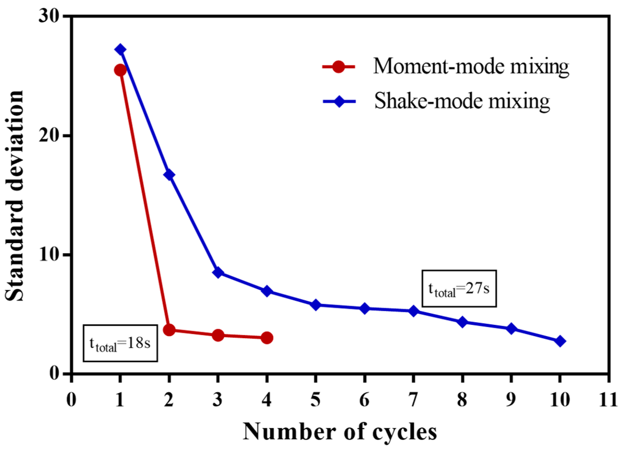
4.3. Mixing Efficiency
5. Conclusions
Acknowledgments
Author Contributions
Conflicts of Interest
References
- Sackmann, E.K.; Fulton, A.L.; Beebe, D.J. The present and future role of microfluidics in biomedical research. Nature 2014, 507, 181–189. [Google Scholar] [CrossRef] [PubMed]
- Noroozi, Z.; Kido, H.; Peytavi, R.; Nakajima-Sasaki, R.; Jasinskas, A.; Micic, M.; Felgner, P.L.; Madou, M.J. A multiplexed immunoassay system based upon reciprocating centrifugal microfluidics. Rev. Sci. Instrum. 2011, 82, 064303. [Google Scholar] [CrossRef] [PubMed] [Green Version]
- Tang, M.; Wang, G.; Kong, S.K.; Ho, H.P. A review of biomedical centrifugal microfluidic platforms. Micromachines 2016, 7, 26. [Google Scholar] [CrossRef]
- Yokota, I.; De, H.; Rinaldo, P.; Molecular, T.K.; Erickson, A. Evaluation of a novel point-of-care system, the i-STAT portable clinical analyzer. Clin. Chem. 1993, 39, 283–287. [Google Scholar]
- Strohmeier, O.; Keller, M.; Schwemmer, F.; Zehnle, S.; Mark, D.; von Stetten, F.; Zengerle, R.; Paust, N. Centrifugal microfluidic platforms: Advanced unit operations and applications. Chem. Soc. Rev. 2015, 44, 6187–6229. [Google Scholar] [CrossRef] [PubMed]
- Pishbin, E.; Navidbakhsh, M. A Centrifugal microfluidic platform for determination of blood Hematocrit level. In Proceedings of the 2015 22nd Iranian Conference on Biomedical Engineering (ICBME), Tehran, Iran, 25–27 November 2015.
- Ducrée, J.; Haeberle, S.; Lutz, S.; Pausch, S.; von Stetten, F.; Zengerle, R. The centrifugal microfluidic Bio-Disk platform. J. Micromech. Microeng. 2007, 17, S103–S115. [Google Scholar] [CrossRef]
- Kazemzadeh, A.; Ganesan, P.; Ibrahim, F.; Kulinsky, L.; Madou, M.J. Guided routing on spinning microfluidic platforms. RSC Adv. 2014, 5, 8669–8679. [Google Scholar] [CrossRef]
- Schwemmer, F.; Hutzenlaub, T.; Buselmeier, D.; Paust, N.; von Stetten, F.; Mark, D.; Zengerle, R.; Kosse, D. Centrifugo-pneumatic multi-liquid aliquoting—Parallel aliquoting and combination of multiple liquids in centrifugal microfluidics. Lab Chip 2015, 15, 3250–3258. [Google Scholar] [CrossRef] [PubMed]
- Cai, Z.; Xiang, J.; Zhang, B.; Wang, W. A magnetically actuated valve for centrifugal microfluidic applications. Sens. Actuators B Chem. 2015, 206, 22–29. [Google Scholar] [CrossRef]
- Gorkin, R.; Soroori, S.; Southard, W.; Clime, L.; Veres, T.; Kido, H.; Kulinsky, L.; Madou, M. Suction-enhanced siphon valves for centrifugal microfluidic platforms. Microfluid. Nanofluid. 2012, 12, 345–354. [Google Scholar] [CrossRef]
- Siegrist, J.; Gorkin, R.; Clime, L.; Roy, E.; Peytavi, R.; Kido, H.; Bergeron, M.; Veres, T.; Madou, M. Serial siphon valving for centrifugal microfluidic platforms. Microfluid. Nanofluid. 2010, 9, 55–63. [Google Scholar] [CrossRef]
- Deng, Y.; Fan, J.; Zhou, S.; Zhou, T.; Wu, J.; Li, Y.; Liu, Z.; Xuan, M.; Wu, Y. Euler force actuation mechanism for siphon valving in compact disk-like microfluidic chips. Biomicrofluidics 2014, 8, 024101. [Google Scholar] [CrossRef] [PubMed]
- Aeinehvand, M.M.; Ibrahim, F.; harun, S.W.; Al-Faqheri, W.; Thio, T.H.G.; Kazemzadeh, A.; Madou, M. Latex micro-balloon pumping in centrifugal microfluidic platforms. Lab Chip 2014, 14, 988–997. [Google Scholar] [CrossRef] [PubMed]
- Zehnle, S.; Schwemmer, F.; Roth, G.; von Stetten, F.; Zengerle, R.; Paust, N. Centrifugo-dynamic inward pumping of liquids on a centrifugal microfluidic platform. Lab Chip 2012, 12, 5142–5145. [Google Scholar] [CrossRef] [PubMed]
- Clime, L.; Brassard, D.; Geissler, M.; Veres, T. Active pneumatic control of centrifugal microfluidic flows for lab-on-a-chip applications. Lab Chip 2015, 15, 2400–2411. [Google Scholar] [CrossRef] [PubMed]
- Gorkin, R.; Nwankire, C.E.; Gaughran, J.; Zhang, X.; Donohoe, G.G.; Rook, M.; O’Kennedy, R.; Ducree, J. Centrifugo-pneumatic valving utilizing dissolvable films. Lab Chip 2012, 12, 2894–2902. [Google Scholar] [CrossRef] [PubMed]
- Kinahan, D.J.; Kearney, S.M.; Kilcawley, N.A.; Early, P.L.; Glynn, M.T.; Ducrée, J. Density-gradient mediated band extraction of leukocytes from whole blood using centrifugo-pneumatic siphon valving on centrifugal microfluidic discs. PLoS ONE 2016, 11, e0155545. [Google Scholar] [CrossRef] [PubMed]
- Soroori, S.; Kulinsky, L.; Kido, H.; Madou, M. Design and implementation of fluidic micro-pulleys for flow control on centrifugal microfluidic platforms. Microfluid. Nanofluid. 2014, 16, 1117–1129. [Google Scholar] [CrossRef] [PubMed]
- Kong, M.C.R.; Salin, E.D. Pneumatically pumping fluids radially inward on centrifugal microfluidic platforms in motion. Anal. Chem. 2010, 82, 8039–8041. [Google Scholar] [CrossRef] [PubMed]
- Abi-Samra, K.; Clime, L.; Kong, L.; Gorkin, R.; Kim, T.H.; Cho, Y.K.; Madou, M. Thermo-pneumatic pumping in centrifugal microfluidic platforms. Microfluid. Nanofluid. 2011, 11, 643–652. [Google Scholar] [CrossRef]
- Serway, R.A. Physics for Scientists & Engineers; Saunders College Pub.: New York, NY, USA, 1986. [Google Scholar]
- Schwemmer, F.; Zehnle, S.; Mark, D.; von Stetten, F.; Zengerle, R.; Paust, N. A microfluidic timer for timed valving and pumping in centrifugal microfluidics. Lab Chip 2015, 15, 1545–1553. [Google Scholar] [CrossRef] [PubMed]
- Cai, Z.; Xiang, J.; Chen, H.; Wang, W. A rapid micromixer for centrifugal microfluidic platforms. Micromachines 2016, 7, 89. [Google Scholar] [CrossRef]
- Abdi, M.; Pishbin, E.; Karimi, A.; Navidbakhsh, M. A Comparative investigation on the performance of different micro mixers: Toward cerebral microvascular analysis. J. Multiscale Model. 2016, 7, 1650008. [Google Scholar] [CrossRef]
- Ren, Y.; Leung, W.W.F. Flow and mixing in rotating zigzag microchannel. Chem. Eng. J. 2013, 215–216, 561–578. [Google Scholar] [CrossRef]
- Squires, T.M.; Quake, S.R. Microfluidics: Fluid physics at the nanoliter scale. Rev. Mod. Phys. 2005, 77, 977. [Google Scholar] [CrossRef]
- Grumann, M.; Geipel, A.; Riegger, L.; Zengerle, R.; Ducrée, J. Batch-mode mixing on centrifugal microfluidic platforms. Lab Chip 2005, 5, 560–565. [Google Scholar] [CrossRef] [PubMed]
- Leung, W.W.F.; Ren, Y. Crossflow and mixing in obstructed and width-constricted rotating radial microchannel. Int. J. Heat Mass Transf. 2013, 64, 457–467. [Google Scholar] [CrossRef]
- La, M.; Park, S.J.; Kim, H.W.; Park, J.J.; Ahn, K.T.; Ryew, S.M.; Kim, D.S. A centrifugal force-based serpentine micromixer (CSM) on a plastic lab-on-a-disk for biochemical assays. Microfluid. Nanofluid. 2013, 15, 87–98. [Google Scholar] [CrossRef]
- Burger, S.; Schulz, M.; von Stetten, F.; Zengerle, R.; Paust, N. Rigorous buoyancy driven bubble mixing for centrifugal microfluidics. Lab Chip 2016, 16, 261–268. [Google Scholar] [CrossRef] [PubMed]


© 2016 by the authors. Licensee MDPI, Basel, Switzerland. This article is an open access article distributed under the terms and conditions of the Creative Commons Attribution (CC-BY) license ( http://creativecommons.org/licenses/by/4.0/).
Share and Cite
Pishbin, E.; Eghbal, M.; Fakhari, S.; Kazemzadeh, A.; Navidbakhsh, M. The Effect of Moment of Inertia on the Liquids in Centrifugal Microfluidics. Micromachines 2016, 7, 215. https://doi.org/10.3390/mi7120215
Pishbin E, Eghbal M, Fakhari S, Kazemzadeh A, Navidbakhsh M. The Effect of Moment of Inertia on the Liquids in Centrifugal Microfluidics. Micromachines. 2016; 7(12):215. https://doi.org/10.3390/mi7120215
Chicago/Turabian StylePishbin, Esmail, Manouchehr Eghbal, Sepideh Fakhari, Amin Kazemzadeh, and Mehdi Navidbakhsh. 2016. "The Effect of Moment of Inertia on the Liquids in Centrifugal Microfluidics" Micromachines 7, no. 12: 215. https://doi.org/10.3390/mi7120215