Article

Non-Linear Piezoelectric Actuator with a Preloaded Cantilever Beam

1
College of Mechanical Science and Engineering, Jilin University, Changchun 130025, China
2
Key Laboratory of Bionics Engineering (Ministry of Education China), Jilin University, Changchun 130025, China
3
College of Communication Engineering, Jilin University, Changchun 130025, China
*
Author to whom correspondence should be addressed.
Micromachines 2015, 6(8), 1066-1081; https://doi.org/10.3390/mi6081066
Submission received: 27 May 2015 / Revised: 30 July 2015 / Accepted: 4 August 2015 / Published: 11 August 2015

Abstract

:
Piezoelectric actuation is widely used for the active vibration control of smart structural systems, and corresponding research has largely focused on linear electromechanical devices. This paper investigates the design and analysis of a novel piezoelectric actuator that uses a piezoelectric cantilever beam with a loading spring to produce displacement outputs. This device has a special nonlinear property relating to converting between kinetic energy and potential energy, and it can be used to increase the output displacement at a lower voltage. The system is analytically modeled with Lagrangian functional and Euler–Lagrange equations, numerically simulated with MATLAB, and experimentally realized to demonstrate its enhanced capabilities. The model is validated using an experimental device with several pretensions of the loading spring, therein representing three interesting cases: a linear system, a low natural frequency system with a pre-buckled beam, and a system with a buckled beam. The motivating hypothesis for the current work is that nonlinear phenomena could be exploited to improve the effectiveness of the piezoelectric actuator’s displacement output. The most practical configuration seems to be the pre-buckled case, in which the proposed system has a low natural frequency, a high tip displacement, and a stable balanced position.

Graphical Abstract

1. Introduction

Piezoelectric actuation has received substantial attention due to its large force output and fast response. In recent years, great efforts have been made to develop piezoelectric actuators with large displacement outputs [1,2,3]. Piezoelectric stack [4,5], multilayer [6], bimorph [7], moonie [8], cymbal [9], and drum piezoelectric actuators [10,11] have been reported [3,12,13]. Although stack and multilayer piezoelectric actuators provide good performance in terms of displacements and forces, their large size and high cost are not suitable for most applications. The moonie, cymbal, and drum piezoelectric actuators can obtain large displacements, but they require a high driving voltage. Bimorph piezoelectric cantilevers have greater applicability because of their greater displacement ability and simple structure [11,14,15,16]. However, their output forces are inversely proportional to the output displacement, and further improvement of the displacement has been limited. Hence, an efficient method that can improve the output performance is still needed [17,18].
Nonlinear structures have also been designed as transducers in recent years [19,20,21,22,23]. The nonlinear response has been shown to exceed the power output and bandwidth of the equivalent linear system. When the standard used for the selection of the transducer is the output amplitude, these nonlinear transducers are better generators. For example, magnetoelastic structures [23,24,25] and vertical cantilever beams with tip masses [26,27,28] were specifically designed to exhibit a nonlinear response and are used to facilitate piezoelectric energy harvesting. Many of these systems demonstrate the advantages of Duffing oscillators and obtain increased bandwidth [20,21,29].
This paper describes the design and analysis of a preloaded piezoelectric actuator with a double-well potential. This actuator has a loading spring mounted between two tips of the bimorph piezoelectric cantilever beam. Its theoretical and experimental investigations are presented. The goal is to demonstrate that it is possible to amplify the top displacements of a preloaded cantilever beam system using a carefully chosen preload spring. A mathematical model is derived from energy principles and numerically simulated across a range of excitation voltages and frequencies. A lumped-parameter nonlinear equations to shown to successfully describe the large displacement response of the preloaded piezoelectric actuator. The displacement response and pretension of the loading spring are compared theoretically, and the substantial advantage of the former is demonstrated.

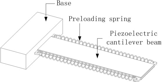
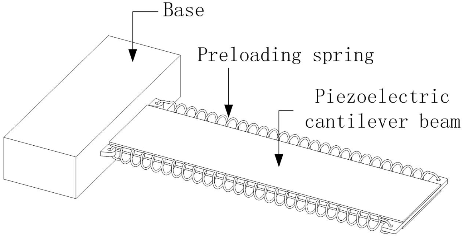
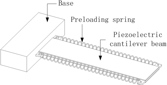
2. Preloaded Piezoelectric Actuators

For a nonlinear piezoelectric actuator, preloaded piezoelectric cantilever beams are considered with a loading spring. Figure 1 illustrates the nonlinear piezoelectric actuator that was modeled, numerically investigated and experimentally tested. The novel device uses a bimorph piezoelectric and two loading springs; the bimorph is clamped at one end to act as a cantilever beam, and the loading spring is mounted between the two tips of the bimorph. Piezoelectric laminates are layered along the beam above and below the electrically neutral substrate material (copper patch), and this structure is commonly referred to as a bimorph [30]. The system is a driven bi-stable oscillator. The pretension forces can be varied according to the stiffness and pretensions of the loading spring, where the stiffness ks and pretensions determine the degree of nonlinearity. At a critical pretension, the elastic restoring force of the beam is overcome by the spring tension, and the cantilever beam is deflected into one of two potential wells. When the pretension is close to the critical value of bifurcation, the effect of the tip displacement of the beam is enhanced.
Figure 1. Schematic diagram of a preloaded piezoelectric actuator.
Micromachines 06 01066 g001
The actuator was driven by a voltage applied to the electrodes of the piezoelectric slice. For this investigation, a deterministic driven voltage of the form v(t) = V0cos(ωvt + φv) was considered, where the driving amplitude V0 and frequency were allowed to vary. The electric field across the thickness of the laminate generates a stress along the piezoelectric components, which bends the beam, and the inertia of the cantilever counteracts the bending force. For the sake of completeness, we fully derive a set of ordinary differential equations for the nonlinear system in the next section.

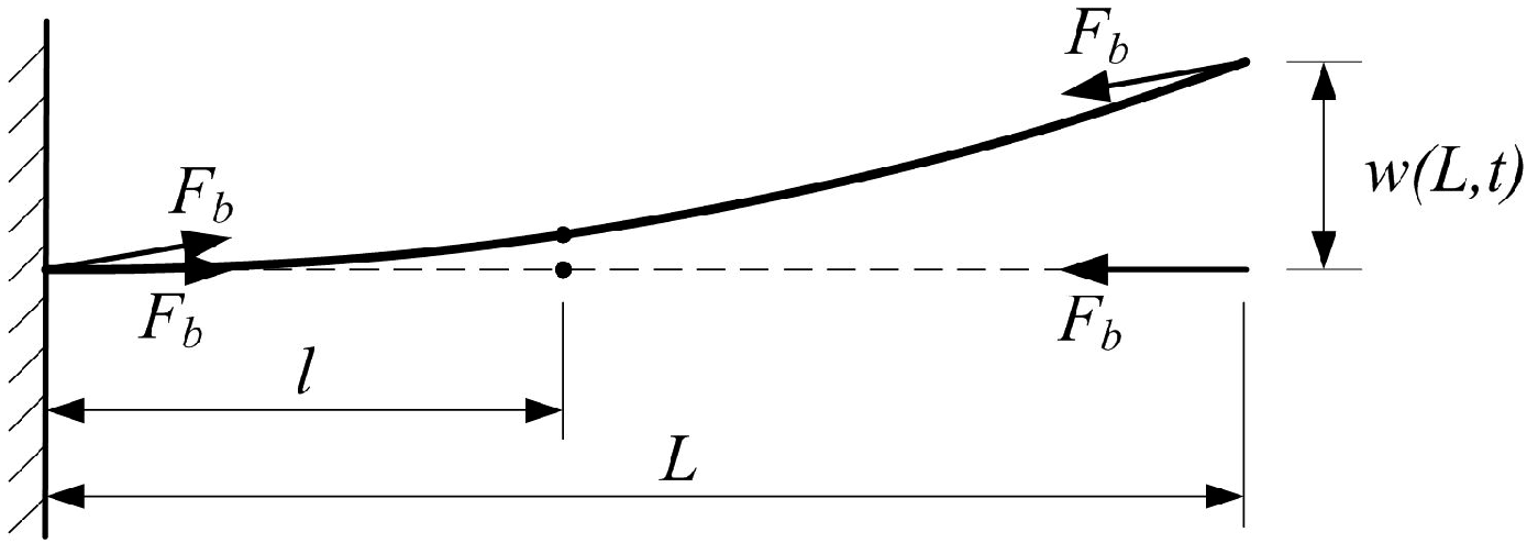
3. Mathematical Model of Preloaded Piezoelectric Actuators

Figure 2 shows the preloaded piezoelectric cantilever beam with length L mounted to the basement with fixed support. The following derivation will use energy methods to develop the governing equations of a bimorph piezoelectric cantilever beam with a loaded spring as an actuator. The energy-based modeling approach for beams has been demonstrated by several studies to be suitable for piezoelectric transducers [31,32,33,34].
Figure 2. Detailed view of the geometry of the analytical actuator model.
Micromachines 06 01066 g002
In the following analysis, the beam is assumed to have uniform inertial and stiffness properties. Two PZT laminates are assumed to be perfectly bonded to either side of the copper patch, and the beam is continuous across the thickness. The first torsional resonance frequency of the beam is much higher than the excitation frequency. Hence, the torsional modes of the beam are neglected, the vibration is purely planar, and the system is studied in the x − y coordinate reference frame. The thickness of the beam is small compared with the length so that the effects of the shear deformation and rotational inertia of the beam can be neglected [27]. The tip displacements of the beam are far smaller than the length, the displacements along the x direction are neglected, and the spatiotemporal transverse deflection w(x,t) is used to build the energy function [24,32].
Consider the beam in Figure 2. The kinetic energy within each part is distributed along the length L of the beam for the substrate as:
T s = 1 2 ρ s A s 0 L ( w ˙ p ( x , t ) ) 2 d x
T p = 1 2 ρ p A p 0 L ( w ˙ p ( x , t ) ) 2 d x
where the overdot indicates a time derivative; L is the length of the electrically active material, which is the same as the base material; ρ is the density; and A is the cross-sectional area. In this paper, the subscripts p, s, and b represent the piezoelectric material, the substrate, and the loaded spring, respectively.
For the inactive substrate, the stored energy is the elastic potential energy of the substrate copper piece expression:
U s = 1 2 V s S _ s T T _ s d V s
where T = cS is the mechanical stress, c is the modulus of elasticity c = E, E is Young’s modulus, S is the mechanical strain, and the superscript T indicates the transpose of the vector. In this paper, we presume that the transverse large orbit oscillations in the double-well potential are sufficiently small to maintain the validity of the Euler–Bernoulli theory. This allows the strain in the beam to be written as the product of the distance from the neutral axis and the second derivative of displacement with respect to the position along the beam. Once the strain is defined in this manner, the following equation can be used:
S _ ( x , z , t ) = z w ( x , t )
where the prime notation ()" is shorthand for ∂2/∂x2. Then, the potential energy in the coordinate reference frame is:
U s = 1 2 E s I s 0 l w ( x , t ) 2 d x
where I s = b h s 3 / 12 is the inertia of the copper slice.
The bending enthalpy for electrically active layers can be written as:
U p = 1 2 V p S _ p T T _ p d V p 1 2 V p E _ p T D _ p d V p
where E and D denote the electric field and displacement, respectively. The piezoelectric laminates maintain an elastic potential, but the applied strain also generates an electric field across the layers because of the piezoelectric effect. In widely used IEEE standard notation, their electromechanical behavior is governed by the following constitutive laws relating the generated electric field to the mechanical stress within a layer [35]:
[ T _ p D _ p ] = [ c p e e ε ] [ S _ p E _ p ]
where ε is the dielectric constant and the superscript e is the piezoelectric coupling coefficient, which relates the stress to the applied electric field. The specification of these relationships will allow electromechanical interactions to be included in the model. Inserting Equation (6) into Equation (5) gives:
U p = 1 2 V p S _ p T E p S _ p d V p V p S _ p T e z x , p E _ z , p d V p 1 2 V p E _ z , p T ε z z , p s E _ z , p d V p
where three parts are included in the elastic potential. Up,1 is independent of the electric field Ez, and the subscript z denotes the direction along the thickness. Up,2 couples the electric field with the stress and energy at the position corresponding to Up,3:
U p = U p , 1 + U p , 2 + U p , 3
where the potential energy Up,s consists of the strain energy resulting from the bending of the piezoelectric patch and is:
U p , 1 = 1 2 E p I p 0 L w ( x , t ) 2 d x
where I p = b h p ( 4 h p 2 + 6 h p h s + 3 h s 2 ) / 12 is the inertia of the piezoelectric slice.
The work performed by the piezoelectric patches in moving or extracting the electrical charge is [27]:
U p , 2 = V p S _ p , x T e p , z x E _ p , z d V p
Similar to a capacitor,
E _ p , z ( t ) = v ( t ) / h p
where hp is the laminate thickness. The piezoelectric coupling coefficient can be written as shown in Equation (9) in terms of the more commonly specified coupling coefficient dij as:
e z x = d 31 c p , x x E
where c x x E = E p and the subscripts i and j of dij refer to the direction of the applied field and the polarity, respectively. Then, Equation (7) can be written as:
U p , 2 = 1 2 d 31 E p b ( h p + h s ) v ( t ) w ( L , t )
The potential application of a piezoelectric cantilever beam as a capacitor is:
U p , 3 = 1 2 C p v ( t ) 2
where C p = b ε z z s L P / h p is the capacitance through one layer.
The potential energy of each piezoelectric slice is:
U p = 1 2 E p I p 0 L w ( x , t ) 2 d x + 1 2 d 31 E p b ( h p + h s ) v ( t ) w ( L , t ) 1 2 C p v ( t ) 2
When the beam is bent, its axis forms a curve, and the distances between its two tips and the potential energy of the loaded spring change. The changing tendency of the loaded spring is in contrast to the potential energy of the beam. The potential energy of the loading spring is:
U b = 1 2 k b ( Δ l b ( t ) ) 2
where kb is the stiffness of the loaded spring and Δlb(t) represents the distance changes in the loading spring.
Δ l b ( t ) = Δ l b , 0 Δ l b , m
where the initial elongation of the loaded spring is Δlb,0 = Llb,0 and lb,0 is the free length of the loaded spring. When the elongation of the loaded spring (Δlb,m) changes as described, we assume that the length of the beam, s(t), is equal to the initial length of the loaded spring, s ( t ) = 0 l 1 + w ( x , t ) 2 d x The initial length is the length of the loaded spring before the beam is bent. In addition, the distance between the two tips of the beam, lb(t), is equal to the instantaneous length of the loaded spring, l b ( t ) = L 2 + w ( L , t ) 2 .
The Lagrangian functional for the electromechanical beam is thus the difference between the kinetic energy and potential energy:
L ( w ˙ , w , w ) = T s + 2 T p + 2 T b U s 2 U p 2 U b
where Tb is the kinetic energy of the loaded spring. Because the mass of the loading spring is assumed to be negligible compared to the beam mass, Tb = 0.
To develop the governing equations of a preloaded piezoelectric cantilever for the actuator, Hamilton’s principle can be applied to yield partial differential equations. However, a more direct method of generating a system of ordinary differential equations may be obtained using the Euler–Lagrange equations. First, an assumption of a modal expansion for w(x,t) should be applied.
With a loading spring, the beam’s first mode of vibration is particularly dominant and obtains the greatest displacement at the tip of beam. Thus, our model and experimental device will utilize this property. We assume that the beam does work in the first mode, and hence, a single-mode approximation of the beam deformation is sufficient. The displacement at any point in the beam is represented as a function of the tip displacement via a function of the beam deformation, ϕ(x):
w ( x , t ) = w ( L , t ) ϕ ( x ) = r ( t ) ϕ ( x )
Thus, Equation (14) can be reduced by incorporating the modal expansion in Equation (15) as:
L ( r , r ˙ , v ) = 1 2 ( ρ s A s + 2 ρ p A p ) r ˙ ( t ) 2 0 L ϕ ( x ) 2 d x 1 2 ( E s I s + 2 E p I p ) r ( t ) 2 0 l ϕ ( x ) 2 d x d 31 E p b ( h p + h s ) v ( t ) ϕ ( L p ) r ( t ) + C p v ( t ) 2 2 U b
A system of ordinary differential coordinates for the modal displacement and flux linkage follow by applying the Euler–Lagrange equations to Equation (16) such that:
d d t L r ˙ L r = Q ( t )
where Q(t) represents a generalized force, and there is no external work applied to the system, namely, Q(t) = 0. Substituting Equation (16) into Equation (17) generates equations for the dynamical system:
M r ¨ ( t ) + K r ( t ) + 2 U b r = D a v 0 cos ( ω v t + φ v )
where:
M = ( ρ s A s + 2 ρ p A p ) 0 L ϕ ( x ) 2 d x
K = ( E s I s + 2 E p I p ) 0 L ϕ ( x ) 2 d x
D a = d 31 E p b ( h p + h s ) ϕ ( L p )
using the following relationship based on the first mode of the linear mode shape:
ϕ ( x ) = 1 cos π x 2 L
for the system in Figure 1 with the parameters listed in Table 1.
Table 1. Parameters of the actuator.
ParameterSymbolValue
Substrate properties
Lengthla120 mm
Widthb20 mm
Thicknesshs0.2 mm
Densityρs8650 kg/m3
Young’s modulusEs112 GPa
Damping ratioζ0.01
Piezoelectric laminate properties
Thicknesshp0.25 mm
Densityρp7700 kg/m3
Young’s modulusEp63 GPa
Coupling coefficientd31−630 × 10−12 C/N
Laminate permittivityεsxx3200 ε0
Permittivity of free spaceε08.854 × 10⁻¹² F/m
Loading spring properties
Stiffnesskb10 kN/m
Lengthlb,0100 mm
PretensionΔlb1 mm

4. Numerical Investigation of the Actuator for Nonlinear Oscillations

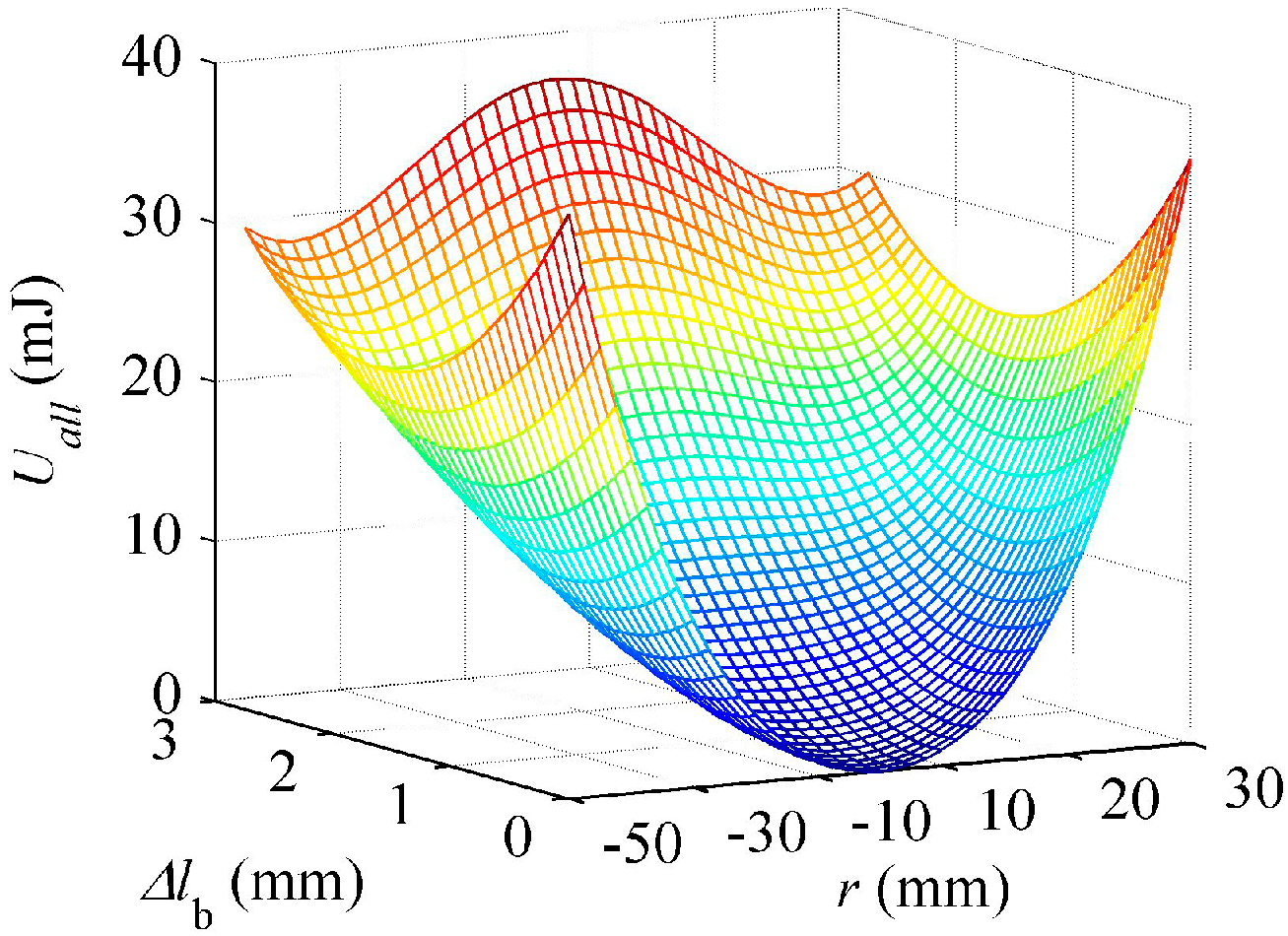
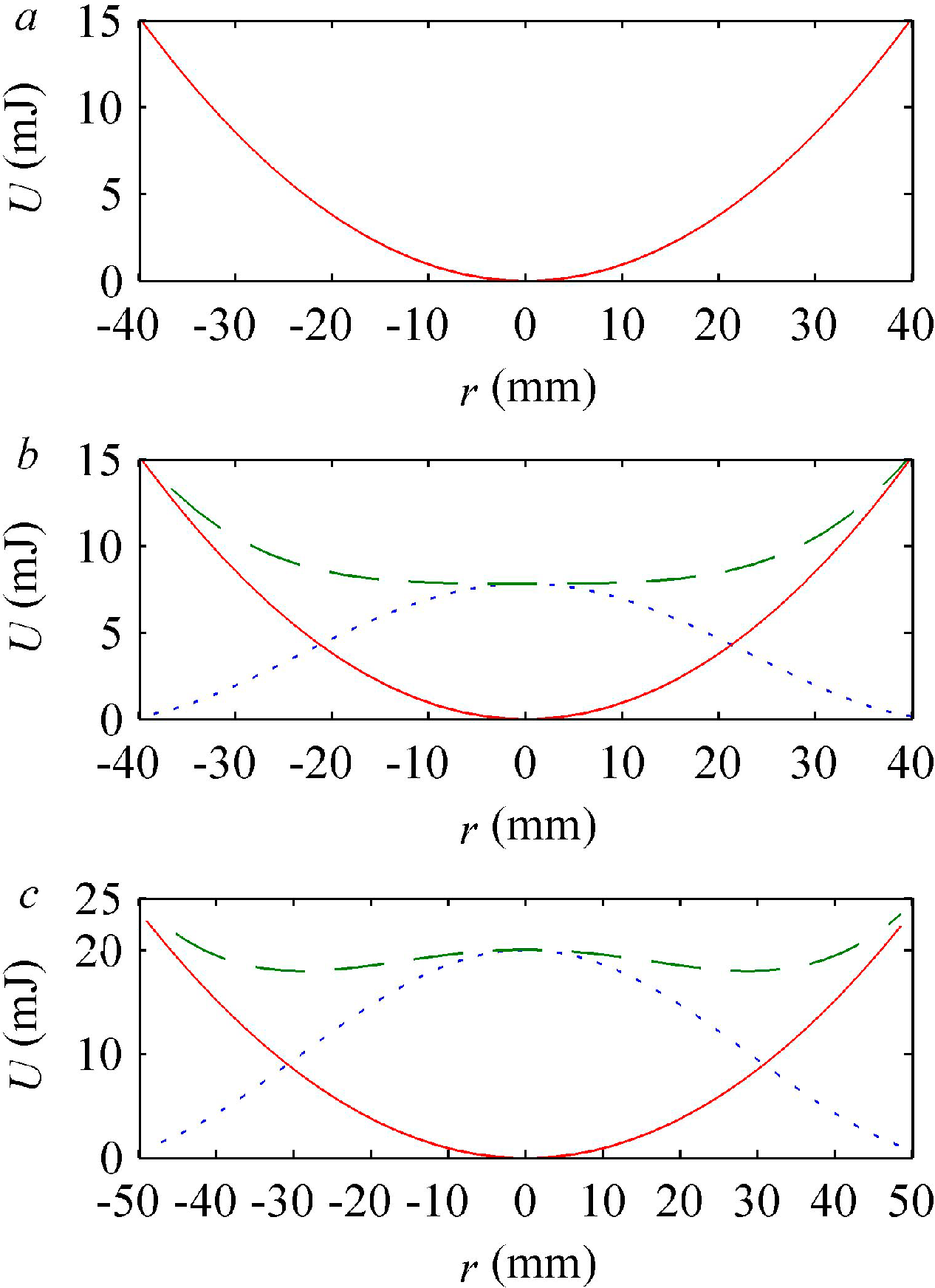
4.1. The Nonlinear Elastic Energy of the Actuator

Figure 3 shows the effects of the loading spring on the total potential energy of the short-circuited actuator, where the distance Δlb is the pretension of the loading spring. From Figure 3, it can be observed that as the pretension is increased, the repelling energy will exceed the total elastic potential of the actuator at a critical value.
Figure 4 illustrates the influence of the pretension forces on the total potential energy of the short-circuited actuator. In each subfigure, the beam’s elastic potential, loading spring potential, and total potential are shown. Table 1 lists the relevant spring characteristics used in calculating the potential energy.
Figure 3. Variation in total elastic energy as a function of tip displacements with preloading.
Micromachines 06 01066 g003
Figure 4. Static mechanical potential energy for a loading spring pretension of (a) 0.01 mm, (b) 1.25 mm and (c) 2 mm. The quadratic restoring potential of the beam (thin solid line) and the nonlinear potential of the loading spring (dotted line) are added to give the total potential energy (dark solid line) as a function of the tip displacement.
Micromachines 06 01066 g004
Figure 4a shows little to no effect on the potential field of the actuator at the tip when the pretension of the loading spring is 0.01 mm, implying that the restoring forces of the loading spring are not sufficiently strong to produce any nonlinear influences. However, upon increasing the pretension to Δlb = 2 mm, a hardening spring force develops before a pitchfork bifurcation generates two new equilibrium points. Figure 4c shows the post-bifurcation result at an initial elongating length of 2 mm, where a symmetric double-well potential can be observed. Because this study involves a novel actuator, it was necessary to investigate its harmonic displacement response.
Figure 5 shows the equilibrium position of the tip and reveals that the post-buckled response has two equilibrium positions. Increases in stiffness or pretension cause the beam to buckle. When the beam buckles, it bends to one side and settles at that equilibrium position. The critical pretension ( Δ l b b = 1.29 mm) is defined as the maximum pretension before buckling. The system is in the pre-buckled state when the pretension is smaller than a critical value. In addition, the system is in the post-buckled state when the pretensions exceed the critical pretensions. In this case, the equilibrium positions are quite sensitive to the stiffness and pretension of the loading spring, and in the simulation study, a stiffness of 10 kN/m was used, unless otherwise stated.
Figure 5. The equilibrium position of the loading piezoelectric actuator (kb = 10 kN/m). The dashed line denotes unstable equilibrium positions.
Micromachines 06 01066 g005
Decreasing the driving voltage from which tip displacements can be used is highly interesting for actuators. To provide insight into the capability of loading the piezoelectric actuator for this purpose, frequency sweeps were obtained via numerical simulation.

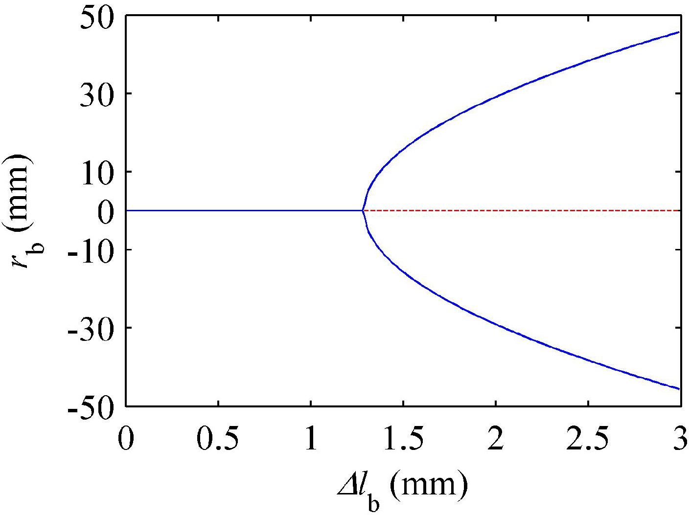
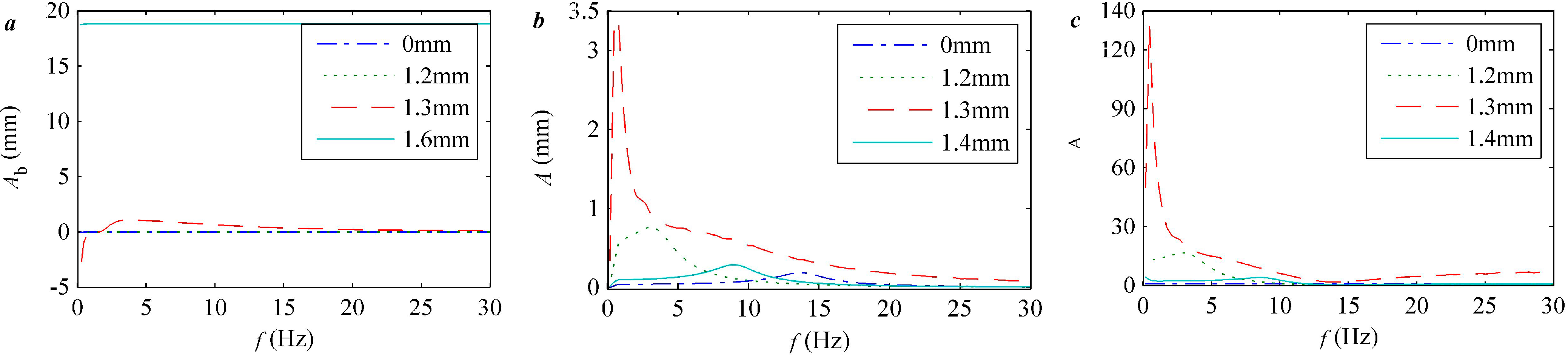
4.2. Pre-Buckled Response

Note that the elastic position energy is the main distinction between the pretension and classic cantilever beams. As shown earlier in the model, the main parameters of interest are the pretension and stiffness of the loading spring and the frequency and amplitude of the driving voltage. The response of the actuator is characterized by its tip displacement under the driving voltage.
The experimental system was modeled using the motion equations of the loaded cantilever beam developed previously to validate the model. In Equation (21), we considered only a very simple model of the beam, where the displacement model is given by Equation (22) and the neutral axis is assumed to remain at the center of the copper beam.
Here, the value of the driving frequency is swept from 0 to 30 Hz. The time response is simulated, with zero initial displacements and velocity, for 8000 cycles to ensure that the transient dynamics have decayed. For the last 100 cycles, the amplitude of the tip is stable. The amplitudes associated with various frequencies can be used to create the frequency response and equilibrium position curve and were obtained through numerical simulation.
The simulated results of the actuator with pre-buckled cantilever beams show that the goal of improving the displacement of the cantilever tip was achieved using the pretensioning of the loading spring (see Figure 6). Figure 6a shows that with increasing pretension of the loading spring, the maximum displacement of the cantilever increases, and the nature frequency of the system decreases. The maximum amplitudes of the system were 0.19, 0.23, 0.31, and 0.77 mm when the pretensions were 0, 0.4, 0.8, and 1.2 mm, respectively.
To study the amplification of a cantilever with a loading spring, the displacement amplification coefficient λA was used, which is the ratio of the amplitude with loading to that without loading. As observed from Figure 6b, λA increases with the pretension of the loading spring when the cantilever beam is pre-buckled. Apparently, the extreme value of the amplification can be obtained when the cantilever approaches the critical scenario.
Figure 7 shows the effects of the input voltage on the displacement amplification coefficient λA; the simulation results show that λA decreases with increasing applied voltage. Specifically, when Δlb = 0.4 mm (Figure 7a) and the applied voltage increased to 200 V from 10 V, the displacement amplification coefficient decreased to 2.1545 from 2.1887; when Δlb = 0.8 mm (Figure 7b), λA decreased to 4.5903 from 4.7681; and when Δlb = 1.2 mm (Figure 7c), λA decreased to 11.4578 from 16.5957. For large applied voltages, the decrease is obvious.
Figure 6. The simulation results for the (a) amplitudes and (b) amplified factors for a stiffness of 10 kN/m, applied voltage of 10 V, and pretension of 0.4, 0.8, and 1.2 mm over a range of frequencies.
Micromachines 06 01066 g006
Figure 7. The simulated results for a stiffness of 10 kN/m, applied voltage of 10 V (dash-dot), 50 V (dot), 100 V (dashed), 200 V (solid), and pretension of (a) 0.4 mm, (b) 0.8 mm and (c) 1.2 mm over a range of frequencies.
Micromachines 06 01066 g007

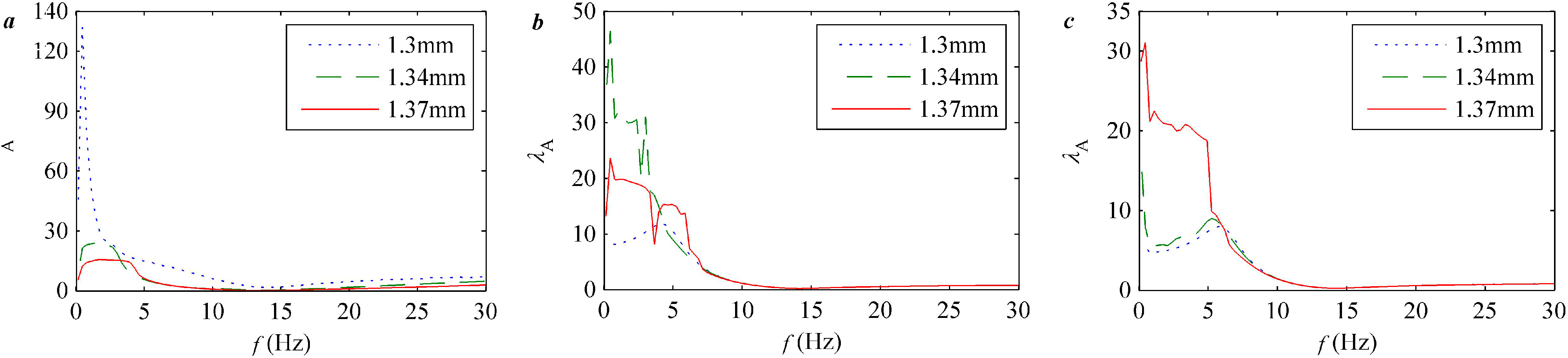
4.3. Post-Buckled Response

Figure 3 and Figure 5 show that with increasing stiffness and pretension of the loading spring, the cantilever buckled. When the electrodes of the actuator short circuit, the post-buckled response exhibits two equilibrium positions. In particular, there are two types of vibrations: in the first type, the beam response oscillates around one of the equilibrium positions, and in the second type, the beam exhibits large oscillations across the unstable zero displacement position. As a drive element, the symmetry of the displacements is as important as the amplitudes; hence, in this paper, the simulation focuses on the latter condition.
According to Figure 8a, when the pretension was 1.3 mm (red dash), the cantilever buckled, and a double-well potential could be observed. Because a pretension of 1.6 mm was utilized, the equilibrium positions Ab ≠ 0. Figure 8b,c show that the displacement of the beam and its amplification coefficient were significantly increased and were greater than the pre-buckled values. λA decreases with increasing pretension when the cantilever is buckled. For instance, λA decreases to 4.3129 from 131.9766 when the pretension increases to 1.6 from 1.3 mm. An interesting result from Figure 8a is that the equilibrium position varied with the frequency of the applied voltage. The oscillations of the cantilever were on either side of the unstable zero displacement position when the frequency was approximately the natural frequency. Under the other condition, the beam oscillated around one of the equilibrium positions because the frequency was far from the natural frequency.
The pretensions of 1.30, 1.34, and 1.37 mm were utilized near the critical pretension of bifurcation, which produces large effects on the amplification of the displacements, as noted earlier. In contrast to the amplification coefficient, three pretension values evaluated at voltages of 10, 100, and 200 V are shown in Figure 9a–c, respectively. Comparing these three figures reveals that the difference in λA is significant; specifically, there is an appropriate driven voltage for each pretension of the cantilever that can produce the maximum λA. The largest λA of the three driven voltages were obtained for 10, 100, and 200 V with pretensions of 1.30, 1.34, and 1.37 mm, respectively. Based on these results, we observe that the appropriate voltage increases with increasing pretension. According to Figure 3, the potential well depths of the cantilever increase with increasing pretension. The relationship between potential energy and kinetic energy in Equation (1) indicates that a deeper potential well requires more input energy, which is provided by the electric energy through the piezoelectric effect. In other words, the required voltage increases with increased pretention, as observed earlier based on the results in Figure 9.
Figure 8. The simulation results for the (a) balance positions, (b) amplitudes of the tip displacement and (c) amplified factors for pretensions of 0 mm (dash-dot), 1.2 mm (dot), 1.3 mm (dash), and 1.6 mm (solid).
Micromachines 06 01066 g008
Figure 9. The simulated results with applied voltages of (a) 10 V, (b) 100 V, and (c) 200 V for pretensions of 1.30 mm (dot), 1.34 mm (dashed), and 1.37 mm (solid).
Micromachines 06 01066 g009

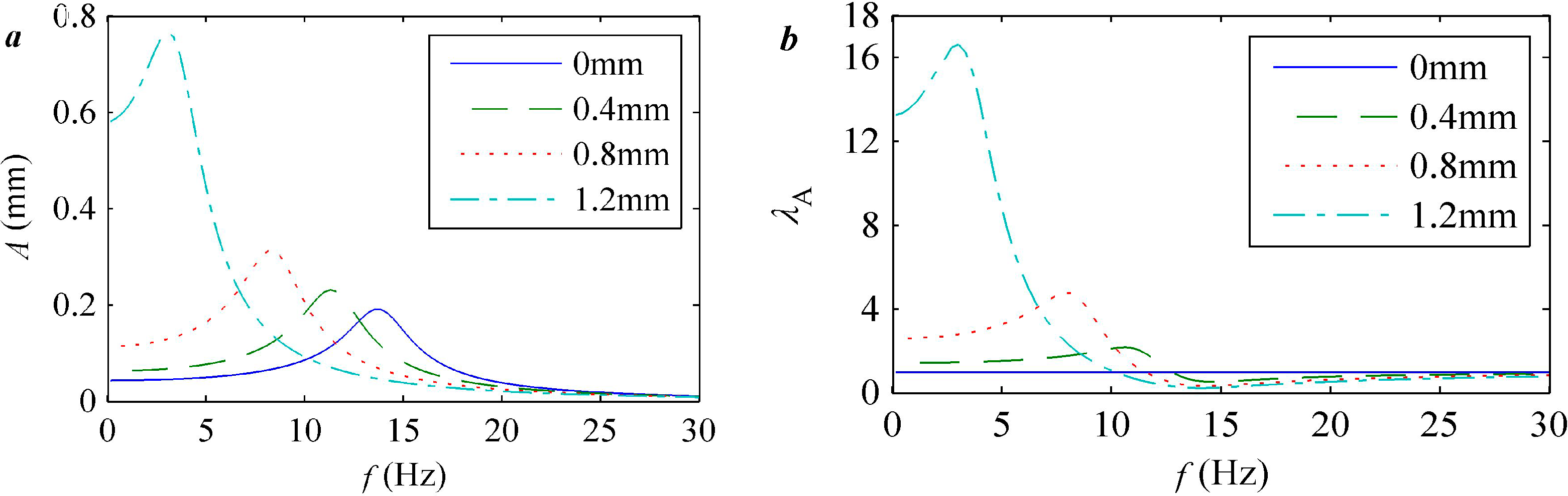
5. Experimental Results and Discussion

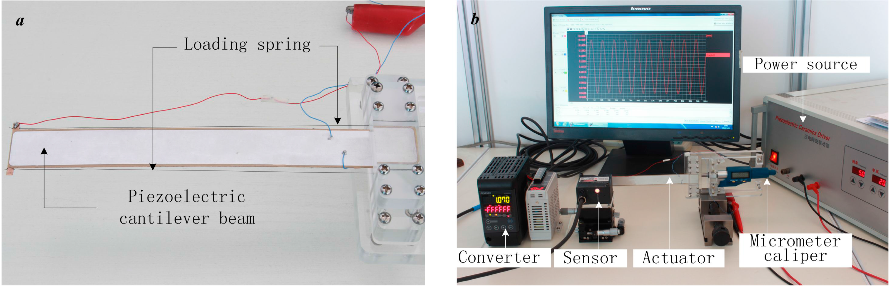
5.1. Measurement and Instrumentation

A picture of the preloaded piezoelectric actuator with a loading spring is shown in Figure 10a. The piezoelectric cantilever beam is installed in the cantilever holder, and the loading spring consists of two line springs that are jointed between the tip of the cantilever beam and the spring holder. The spring holder was attached to a clamping device that could be withdrawn or pushed toward the holder of the cantilever along secured tracks to apply the preloading forces. The distance between the spring holder and cantilever holder can be varied using the digital micrometer caliper between them, which is used to change the pretension of the loading spring. Figure 10a shows the effects of positioning the spring within the critical bifurcation distance.
Figure 10. (a) The structure of the experimental pretension actuator; (b) the remaining necessary experimental equipment.
Micromachines 06 01066 g010
A laser displacement sensor (Keyence LK-H020) and a DC power supply (MS2-H50) were used to record the transverse beam displacement. The laser displacement sensor and remaining required equipment are shown in Figure 10b. The measured signals (tip displacement) were passed through a converter (Keyence LK-G5001V), which was used to output a digital signal from an analog input for use by the computer.

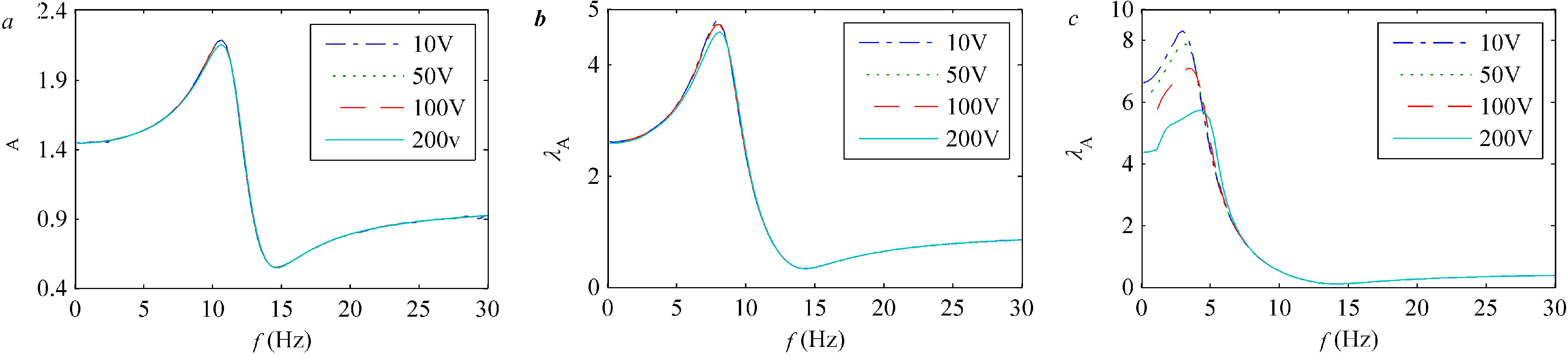
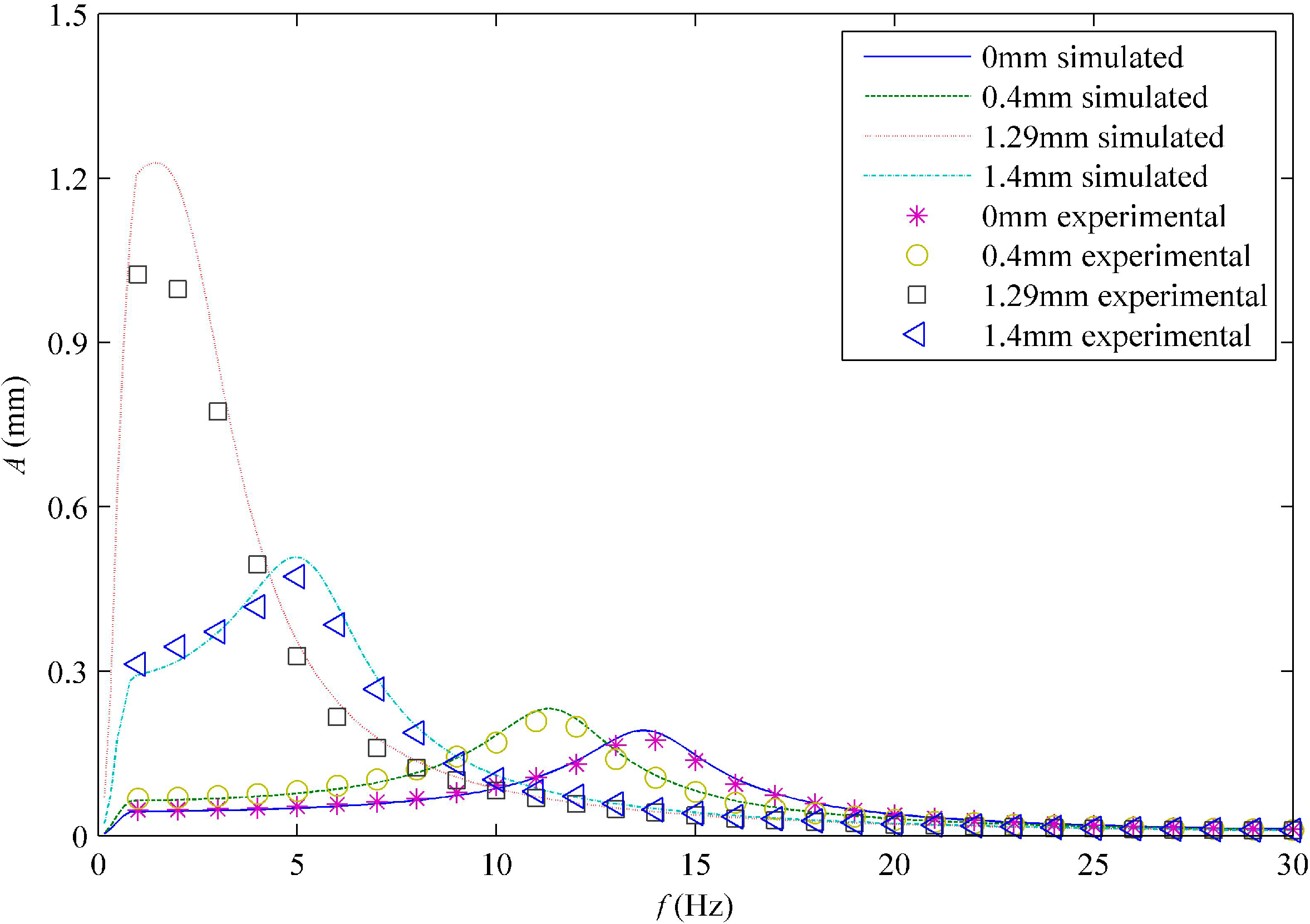
5.2. Comparisons of Experiment with Theory

A picture of the preloaded piezoelectric actuator with adjustable pretension is shown in Figure 10a. The actuator consists of a bimorph piezoelectric beam and two preloaded springs with the physical parameters listed in Table 1. The piezoelectric beam is vertically clamped at one end and held in such a way as to alleviate the influence of gravity. The piezoelectric laminates are connected in parallel with one another using leads. The entire beam was then placed in series with a power source with variable frequency and amplitude. The tip displacement generated by the voltage applied to the actuators was then measured. The damped linear natural frequency of the cantilever was determined by averaging 10 impulse tests:
c = 2 m j T r ln A 1 A j + 1
These data were then studied to determine the non-dimensional damping ratio:
ζ = c c c = c 2 k m
This predicted a non-dimensional damping ratio of ζ = 0.0163 and a damped natural frequency of 13.67 Hz, in good agreement with the modeled damped natural frequency of 13.69 Hz. A deviation is anticipated because the model neglects the very thin silver conducting electrode and the thickness of the epoxy adhesive coating layer used to bond the piezoelectric patch and substrate together.
The experiments were performed to validate the phenomenological results of the numerical studies. Specifically, the amplified tip displacement response was investigated by performing frequency experiments from 1 to 30 Hz. The amplitude of the driven voltage was maintained at 10 V. The corresponding tip displacement with pretensions of 0.4 and 1.29 mm across the frequency range exhibits a stiffness softening behavior, and the amplification of the displacement was clear. In addition, with a pretension of 1.4 mm, an intrawell hopping behavior was observed, and the amplifier effect on the displacement was reduced. Figure 11 shows the simulation results corresponding to the measurements and similar trends in the simulation and experimental results. The cantilever beam is pre-buckled with pretensions of 0, 0.4, or 1.29 mm, and λA increases with increasing pretension. However, the amplitudes of the tip displacements increased from 0.19 mm to 1.2 mm when the pretension increased from zero to 1.29 mm. When the pretension was 1.4 mm, the beam was post-buckled, and the amplitudes of the tip displacements decreased to 0.5 mm. The balance position was one of two equilibrium values of the potential. The resonant piezoelectric cantilever beam provides greater values for the extremes of the tip displacement output only when the pretension is at or very close to its critical bifurcation pretension (1.29 mm); then, the displacement output of the actuator can be six times larger than the actuator without pretension. Hence, a displacement output that can increase by an order of magnitude larger over a frequency range can be expected with this device.
Figure 11. The response measured via laser experiment (points) and simulation (lines) for a stiffness of 10 kN/m and pretensions of Δlb = 0 mm (asterisks and solid line), 0.4 mm (circles and dashed line), 1.29 mm (triangles and dotted line), and 1.4 mm (squares and dashed-dotted line) over a range of frequencies.
Micromachines 06 01066 g011

6. Conclusions

This paper characterized the displacement output from a piezoelectric actuator with a loading spring. Most importantly, the amplifier effects of the displacement response were numerically predicted and experimentally validated. A complete nonlinear model was derived with an analytical preloaded piezoelectric cantilever beam formulation and appropriate modal expressions accounting for discontinuous piezoelectric laminates. The tip displacement output of the piezoelectric actuator can be as large as six times that of the actuator without pretension. The model was capable of accurately predicting the key characteristics of the piezoelectric actuator, such as resonant frequency, tip displacement and pitchfork bifurcation, as well as the amplified effects on the displacements in the experimental system. The amplifier effect of the actuator is significant near the critical buckling pretension, and the amplificatory post-buckled factor is larger than the pre-buckled factor. However, the balance position is unstable and affected by the driven voltage, frequency and load of the actuator. The pre-buckled simulation results show that the tip displacement amplificatory factor decreases with increasing driven voltage, and the post-buckled results show that there is an optimal match between the driven voltage and the pretension. Thus, the proposed preloaded piezoelectric actuator approach may be more practical in applications than traditional configurations.

Acknowledgments

This project has been supported by the National Natural Science Foundation of China (Grant No. 51405189 and 51277088) and the China Postdoctoral Science Foundation (No. 2014M551195 and 2015M570270).

Author Contributions

Yue Wu developed the designed model, conceived and designed the experiments, collected and analyzed the data, and drafted the manuscript. Jingshi Dong and Qingping Liu checked the results. Zhigang Yang and Xinbo Li checked the manuscript.

Conflicts of Interest

The authors declare no conflicts of interest.

References

  1. Aksel, E.; Jones, J.L. Advances in lead-free piezoelectric materials for sensors and actuators. Sensors 2010, 10, 1935–1954. [Google Scholar] [PubMed]
  2. Abuzaid, A.; Hrairi, M.; Dawood, M.S.I. Survey of active structural control and repair using piezoelectric patches. Actuators 2015, 4, 77–98. [Google Scholar]
  3. Gómez Alvarez-Arenas, T. Air-coupled piezoelectric transducers with active polypropylene foam matching layers. Sensors 2013, 13, 5996–6013. [Google Scholar] [PubMed]
  4. Goldfarb, M.; Celanovic, N. Modeling piezoelectric stack actuators for control of micromanipulation. IEEE Control Syst. 1997, 17, 69–79. [Google Scholar]
  5. Jakiela, S.; Debski, P.; Dabrowski, B.; Garstecki, P. Generation of nanoliter droplets on demand at hundred-Hz frequencies. Micromachines 2014, 5, 1002–1011. [Google Scholar]
  6. Furuta, A.; Uchino, K. Dynamic observation of crack propagation in piezoelectric multilayer actuators. J. Am. Ceram. Soc. 1993, 76, 1615–1617. [Google Scholar]
  7. Low, T.; Guo, W. Modeling of a three-layer piezoelectric bimorph beam with hysteresis. J. Microelectromech. Syst. 1995, 4, 230–237. [Google Scholar] [CrossRef]
  8. Dogan, A.; Xu, Q.; Onitsuka, K.; Yoshikawa, S.; Uchino, K.; Newnham, R.E. High displacement ceramic metal composite actuators (moonies). Ferroelectrics 1994, 156, 1–6. [Google Scholar] [CrossRef]
  9. Ochoa, P.; Villegas, M.; Rodriguez, M.; Fernandez, J. Statistic analysis of electromechanical response in cymbal piezocomposites. J. Eur. Ceram. Soc. 2006, 27, 4173–4176. [Google Scholar] [CrossRef]
  10. Sun, C.L.; Lam, K.H.; Chan, H.L.W.; Zhao, X.-Z.; Choy, C.L. A Novel Drum Piezoelectric-Actuator. Appl. Phys. A 2006, 84, 385–390. [Google Scholar] [CrossRef]
  11. Her, S.-C.; Lin, C.-S. Vibration analysis of composite laminate plate excited by piezoelectric actuators. Sensors 2013, 13, 2997–3013. [Google Scholar] [CrossRef] [PubMed]
  12. Lee, H.; Zhang, S.; Bar-Cohen, Y.; Sherrit, S. High temperature, high power piezoelectric composite transducers. Sensors 2014, 14, 14526–14552. [Google Scholar] [CrossRef] [PubMed]
  13. Liu, J.; Li, M.; Qin, L.; Liu, J. Active design method for the static characteristics of a piezoelectric six-axis force/torque sensor. Sensors 2014, 14, 659–671. [Google Scholar] [CrossRef] [PubMed]
  14. Dong, X.; Peng, Z.; Hua, H.; Meng, G. Modeling of the through-the-thickness electric potentials of a piezoelectric bimorph using the spectral element method. Sensors 2014, 14, 3477–3492. [Google Scholar] [CrossRef] [PubMed]
  15. El-Sayed, A.; Abo-Ismail, A.; El-Melegy, M.; Hamzaid, N.; Osman, N. Development of a micro-gripper using piezoelectric bimorphs. Sensors 2013, 13, 5826–5840. [Google Scholar] [CrossRef] [PubMed]
  16. El-Sayed, A.; Hamzaid, N.; Abu Osman, N. Piezoelectric bimorphs’ characteristics as in-socket sensors for transfemoral amputees. Sensors 2014, 14, 23724–23741. [Google Scholar] [CrossRef] [PubMed]
  17. Tian, X.; Yang, Z.; Liu, Y.; Shen, Y.; Chen, S. Structural design and experimental analysis of a piezoelectric vibration feeder with a magnetic spring. Micromachines 2014, 5, 547–557. [Google Scholar] [CrossRef]
  18. Zhang, J.; Wu, Z.; Jia, Y.; Kan, J.; Cheng, G. Piezoelectric bimorph cantilever for vibration-producing-hydrogen. Sensors 2012, 13, 367–374. [Google Scholar] [CrossRef] [PubMed]
  19. Mann, B.P.; Sims, N.D. Energy harvesting from the nonlinear oscillations of magnetic levitation. J. Sound Vib. 2009, 319, 515–530. [Google Scholar] [CrossRef]
  20. Erturk, A.; Hoffmann, J.; Inman, D. A piezomagnetoelastic structure for broadband vibration energy harvesting. Appl. Phys. Lett. 2009, 94, 254102. [Google Scholar] [CrossRef]
  21. Burrow, S.; Clare, L.; Carrella, A.; Barton, D. Vibration Energy Harvesters with Non-linear Compliance. Proc. SPIE 2008, 6928, 692807. [Google Scholar]
  22. Guyomar, D.; Lallart, M. Recent progress in piezoelectric conversion and energy harvesting using nonlinear electronic interfaces and issues in small scale implementation. Micromachines 2011, 2, 274–294. [Google Scholar] [CrossRef]
  23. Priya, S.; Ryu, J.; Park, C.-S.; Oliver, J.; Choi, J.-J.; Park, D.-S. Piezoelectric and magnetoelectric thick films for fabricating power sources in wireless sensor nodes. Sensors 2009, 9, 6362–6384. [Google Scholar] [CrossRef] [PubMed]
  24. Stanton, S.C.; McGehee, C.C.; Mann, B.P. Nonlinear dynamics for broadband energy harvesting: Investigation of a bistable piezoelectric inertial generator. Phys. D Nonlinear Phenom. 2010, 239, 640–653. [Google Scholar] [CrossRef]
  25. Zhou, S.; Cao, J.; Inman, D.J.; Lin, J.; Liu, S.; Wang, Z. Broadband tristable energy harvester: Modeling and experiment verification. Appl. Energy 2014, 133, 33–39. [Google Scholar] [CrossRef]
  26. Bilgen, O.; Ali, S.F.; Friswell, M.I.; Litak, G.; de Angelis, M. Non-linear piezoelectric vibration energy harvesting from a vertical cantilever beam with tip mass. In Proceedings of the ASME 2013 Conference on Smart Materials, Adaptive Structures and Intelligent Systems, Snowbird, UT, USA, 16–18 September 2013.
  27. Friswell, M.I.; Ali, S.F.; Bilgen, O.; Adhikari, S.; Lees, A.W.; Litak, G. Non-linear piezoelectric vibration energy harvesting from a vertical cantilever beam with tip mass. J. Intell. Mater. Syst. Struct. 2012, 23, 1505–1521. [Google Scholar] [CrossRef]
  28. Kim, P.; Bae, S.; Seok, J. Resonant behaviors of a nonlinear cantilever beam with tip mass subject to an axial force and electrostatic excitation. Int. J. Mechan. Sci. 2012, 64, 232–257. [Google Scholar] [CrossRef]
  29. Caliò, R.; Rongala, U.; Camboni, D.; Milazzo, M.; Stefanini, C.; de Petris, G.; Oddo, C. Piezoelectric energy harvesting solutions. Sensors 2014, 14, 4755–4790. [Google Scholar] [CrossRef] [PubMed] [Green Version]
  30. Hagood, N.W.; Chung, W.H.; Von Flotow, A. Modelling of piezoelectric actuator dynamics for active structural control. J. Intell. Mater. Syst. Struct. 1990, 1, 327–354. [Google Scholar] [CrossRef]
  31. Wang, Q.-M.; Eric Cross, L. Constitutive equations of symmetrical triple layer piezoelectric benders. IEEE Trans. Ultrason. Ferroelectr. Frequency Control 1999, 46, 1343–1351. [Google Scholar] [CrossRef] [PubMed]
  32. Sodano, H.A.; Park, G.; Inman, D. Estimation of electric charge output for piezoelectric energy harvesting. Strain 2004, 40, 49–58. [Google Scholar] [CrossRef]
  33. Dutoit, N.E.; Wardle, B.L.; Kim, S.-G. Design considerations for mems-scale piezoelectric mechanical vibration energy harvesters. Integr. Ferroelectr. 2005, 71, 121–160. [Google Scholar] [CrossRef]
  34. Stanton, S.; Mann, B. Harvesting energy from the nonlinear oscillations of a bistable piezoelectric inertial energy generator. In Proceedings of the ASME 2009 International Design Engineering Technical Conferences and Computers and Information in Engineering Conference, San Diego, CA, USA, 30 August–2 September 2009.
  35. Meitzler, A.; Tiersten, H.F.; Warner, A.W.; Berlincourt, D.; Couqin, G.A.; Welsh, F.S., III. ANSI/IEEE Std 176-1987: IEEE Standard on Piezoelectricity; IEEE: Piscataway, NJ, USA, 1988. [Google Scholar]

