Article

A Fast, Large-Stroke Electrothermal MEMS Mirror Based on Cu/W Bimorph

Department of Electrical & Computer Engineering, University of Florida, Gainesville, FL 32611, USA
*
Author to whom correspondence should be addressed.
Micromachines 2015, 6(12), 1876-1889; https://doi.org/10.3390/mi6121460
Submission received: 23 October 2015 / Revised: 19 November 2015 / Accepted: 24 November 2015 / Published: 2 December 2015
(This article belongs to the Special Issue Optical Microsystems)

Abstract

:
This paper reports a large-range electrothermal bimorph microelectromechanical systems (MEMS) mirror with fast thermal response. The actuator of the MEMS mirror is made of three segments of Cu/W bimorphs for lateral shift cancelation and two segments of multimorph beams for obtaining large vertical displacement from the angular motion of the bimorphs. The W layer is also used as the embedded heater. The silicon underneath the entire actuator is completely removed using a unique backside deep-reactive-ion-etching DRIE release process, leading to improved thermal response speed and front-side mirror surface protection. This MEMS mirror can perform both piston and tip-tilt motion. The mirror generates large pure vertical displacement up to 320 μm at only 3 V with a power consumption of 56 mW for each actuator. The maximum optical scan angle achieved is ±18° at 3 V. The measured thermal response time is 15.4 ms and the mechanical resonances of piston and tip-tilt modes are 550 Hz and 832 Hz, respectively.

Graphical Abstract

1. Introduction

Microelectromechanical systems (MEMS) scanning mirrors are widely used in a variety of applications such as Fourier transform (FT) spectroscopy [1,2], confocal microscopy [3], optical coherence tomography [4,5], optical switches [6], and projection displays [7]. Scan range, speed, driving voltage, power consumption and footprint are among the key parameters for MEMS scanning mirrors. In particular, MEMS-based FT spectrometers require vertical scanning of hundreds of micrometers for sufficient spectral resolution [2,8]. There are several actuation mechanisms to achieve vertical scans, including electrothermal [9,10], electrostatic [11,12], and piezoelectric [13]. However, it is very challenging to achieve such a large vertical scan range, especially at non-resonant operation.
Wu et al. proposed a lateral-shift-free (LSF) electrothermal bimorph actuator design that can generate pure vertical displacement up to 1 mm [9] and several large-range MEMS mirrors with vertical scans over 600 μm based on this design have been reported [8,14]. The schematic of an LSF bimorph actuator is shown in Figure 1, which consists of three bimorph segments and two straight frames. A bimorph is made of two layers with different coefficients of thermal expansion (CTEs); temperature change will induce a bending or tilt motion from the bimorph. The basic idea of the LSF bimorph actuator is to utilize the angular tilts of the bimorphs to generate vertical displacement and allow the two frames to amplify the vertical displacement. Meanwhile, the reason that the bimorph is divided into three segments is to achieve zero angular tilt and zero lateral shift at the tip of the actuator. To fully compensate the angular tilt and lateral shift, the arc angles of the three bimorph beams must satisfy the requirement that the arc angle of bimorph II, α, is twice that of bimorphs I and III, θ, as shown in Figure 1. As the arc angle of a bimorph beam is proportional to its length, the length of bimorph II is set to be twice that of bimorph I and III. With the selected bimorph lengths, the angular tilt and lateral shift will be canceled at the tip of bimorph III, while the vertical displacements of three bimorph segments are also canceled. To generate vertical displacement at the tip of bimorph III where a mirror plate is connected, two frames with the same length that point in opposite directions are essential to provide the vertical displacement and meanwhile maintain the lateral-shift-free piston motion of the mirror plate. The vertical position of the mirror plate can be precisely controlled by applying a current to a resistor embedded inside the bimorph. The current generates Joule heating and thus a temperature change in the LSF actuator which consequently produces a pure vertical motion of the mirror plate.
Figure 1. Schematic of the Al/SiO2-based lateral-shift-free design, with thick silicon as frame.
Micromachines 06 01460 g001
However, with the range scaling up, the response time of the actuator is also increased greatly, up to hundreds of milliseconds [8,14]. In the previous reported Al/SiO2-based LSF bimorph actuator designs [8,9,14], Al and SiO2 were employed to serve as the active layers of the bimorphs due to their large CTE difference. Joule heating was generated by a thin Pt layer acting as the embedded heater. Due to the relatively low Young’s modulus of both the Al and SiO2 layers, a thick silicon layer was kept to ensure the rigidity of the frames, as shown in Figure 1. However, the thick silicon layer will bring large extra thermal capacitance for the LSF actuator, which leads to a slow thermal response of over 100 ms. This is particularly severe when long frames are needed to generate large vertical range [8,14]. As a result, the operation frequency of the scanning mirrors based on Al/SiO2 LSF actuators is typically limited within 10 Hz to keep the large scan range [8].
In this paper, a new LSF bimorph actuator with high-Young’s-modulus materials Cu and W as the two bimorph layers is proposed, and at the same time Cu/W/Cu thin-film multimorph [15] frames are used to replace the thick Si frames to greatly reduce the thermal capacitance of the LSF actuator. Also, the W layer itself is employed as the embedded heater. Large scan range with small shift and fast thermal response has been achieved. The design, fabrication and characterization of the MEMS mirror based on the optimized Cu/W based LSF actuator are described in the following sections.

2. Working Principle

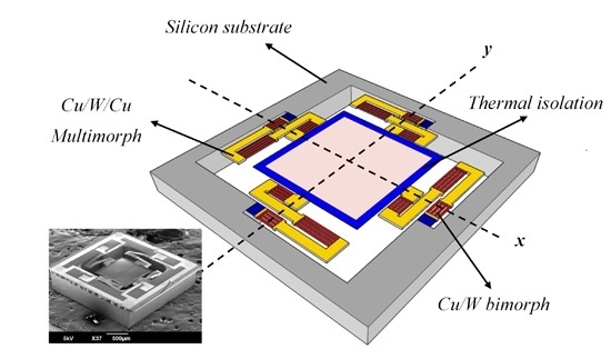
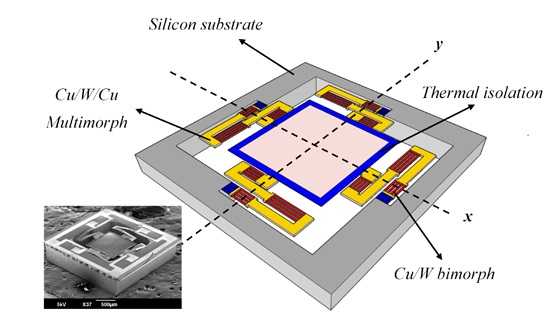
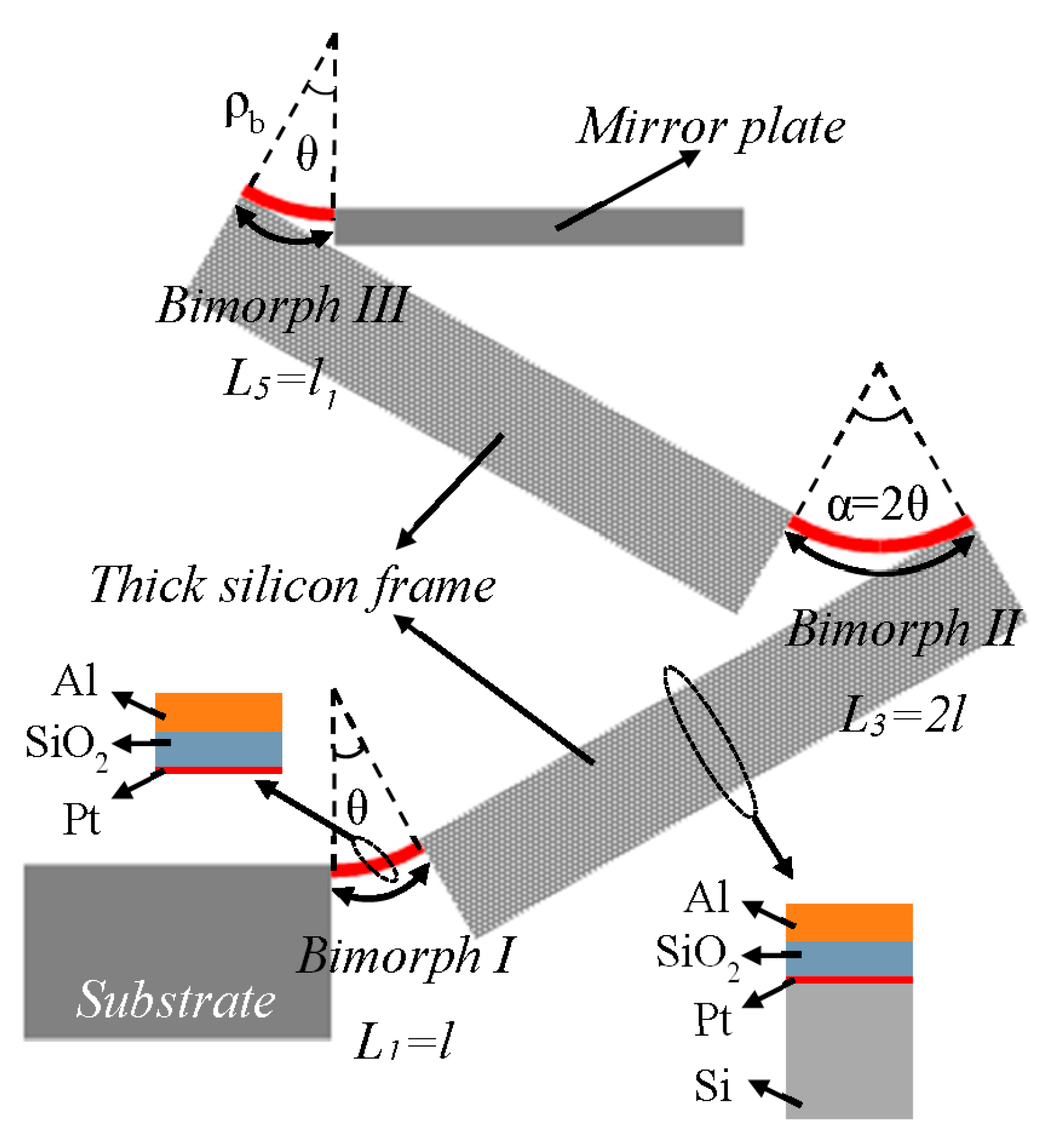
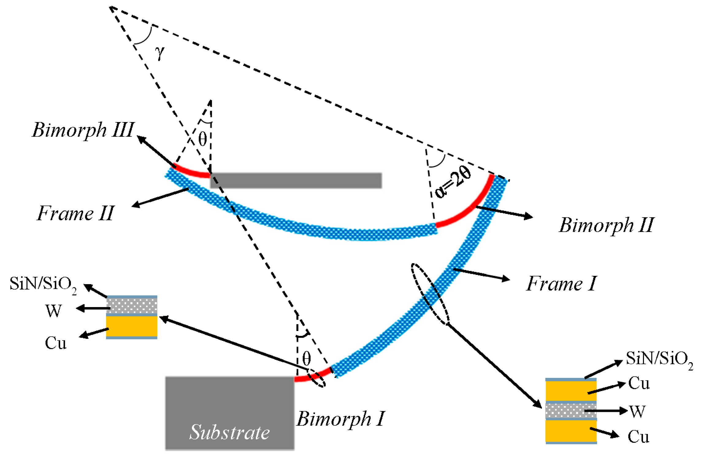
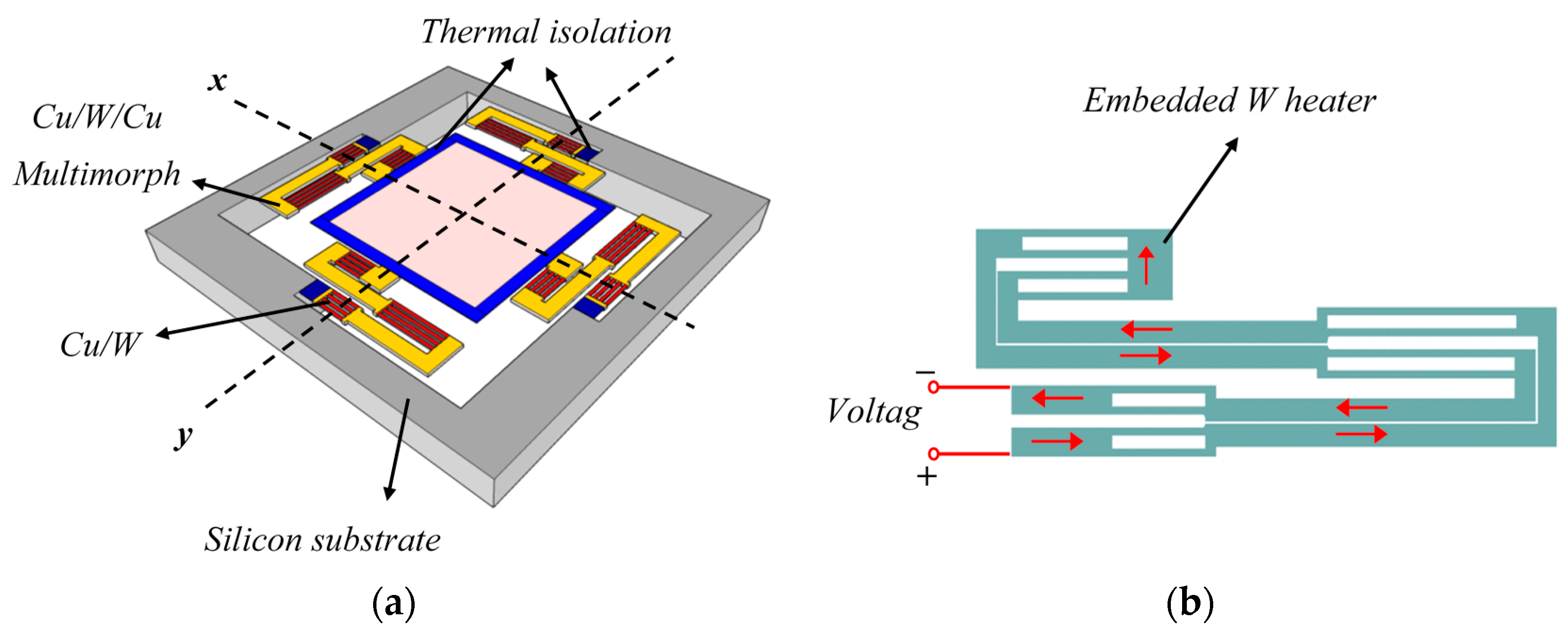
2.1. LSF Cu/W Bimorph Actuator Concept

The new LSF bimorph actuator design is illustrated in Figure 2, which consists of five segments: Bimorph I, Frame I, Bimorph II, Frame II and Bimorph III. All three bimorph segments are composed of Cu and W as the materials of the bilayers while the two frames are composed of a stack of Cu/W/Cu thin-film layers that form a symmetric layer structure. Compared to the prior thick Si frames, the thin-film metal frames provide much faster thermal response. The symmetric Cu/W/Cu frames are used to minimize the curling.
Figure 2. Schematic of the Cu/W-based LSF actuator, with a Cu/W/Cu multimorph as the frame.
Micromachines 06 01460 g002

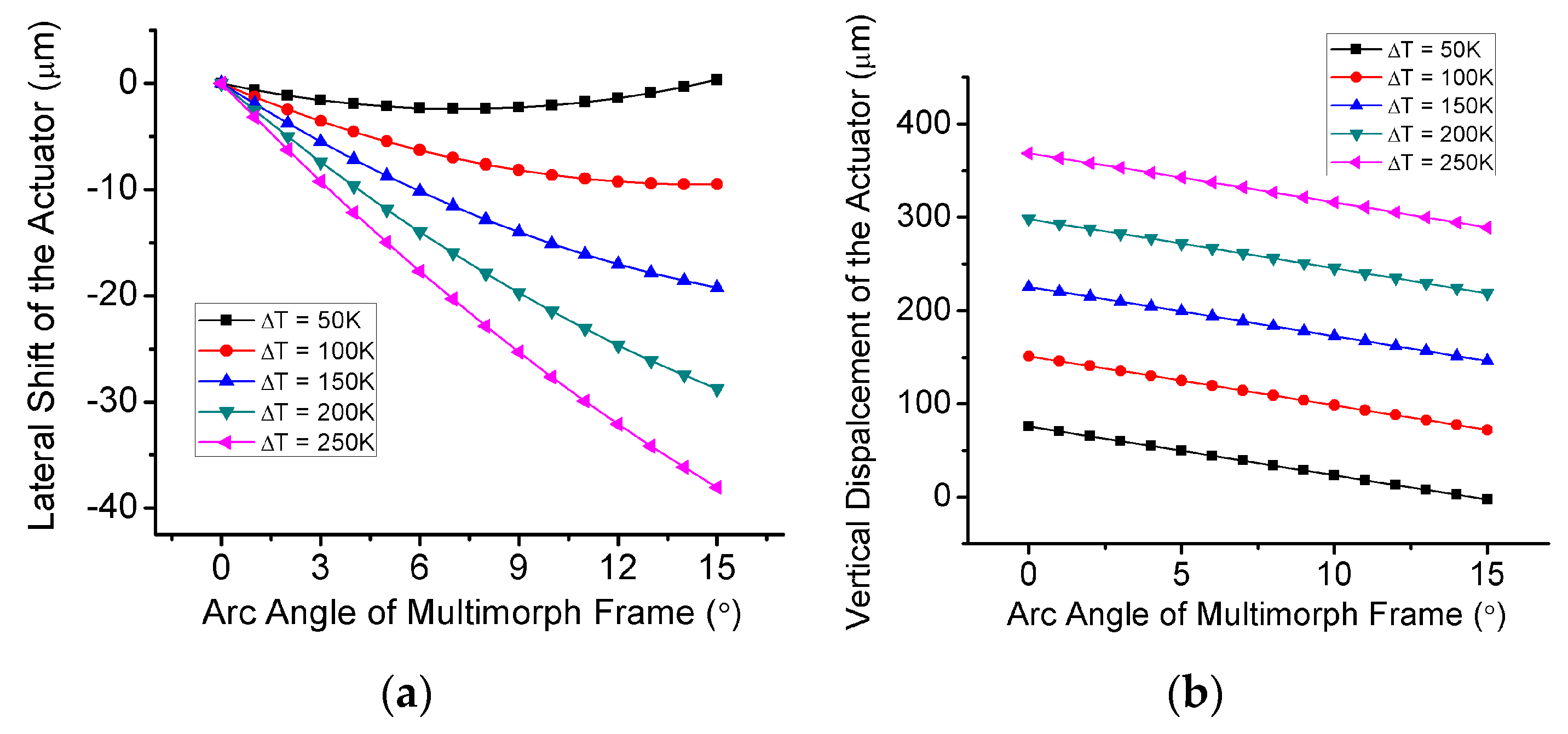
2.2. Tilt/Shift Analysis of the LSF Cu/W Bimorph Actuator

Unlike the thick Si frames, the thin-film frames are not straight due to residual thin-film stresses. As a result, the lateral shift may not be fully canceled, which may lead to a reduction in the vertical displacement. Thus, the angular tilt cancellation, the lateral shift compensation, and the corresponding vertical displacement must be re-analyzed for this new LSF actuator.
As shown in Figure 2, the angular tilt φ at the tip of bimorph III is equal to the sum of the arc angles of all five segments of the LSF bimorph actuator. In the ideal case, we have:
φ =   n = 1 5 i =   θ + γ 2 θ γ + θ = 0
where i is the arc angle of the ith bimorph or frame segment. The angular tilt at the tip of bimorph III will be zero as long as the length of bimorph II is twice that of bimorphs I and III, and the frames have the same length. In Equation (1), we assume that (θ + γ) is less than 90° for vertical displacement amplification, which is also the case for the device design reported here.
For the lateral shift compensation and the corresponding vertical displacement, first we consider the segments as separate cantilever beams with lengths Li and arc angles i where i = 1, …, 5. Assume all the segments start at O(0 0), and then the vectors of the end points of the five segments can be expressed as:
A i = ( X i   Y i )
where X i and Y i are respectively the lateral projection and vertical displacement for end tip of the ith segment, which are given by:
X i = L i × sin i i
Y i = L i i ( 1 cos i )
Now if the segments are connected in a series as shown in Figure 1, all segments except bimorph I will rotate with their angular tilts from their preceding segments. If we denote the vector of the end point of the ith segment of the LSF actuator as Ai,c = (Xi,c Yi,c) when the five segments are connected and A 1 , c = A 1 , then we have:
A i , c = A i 1 , c + A i × ( cos n = 1 i 1 i sin n = 1 i 1 i sin n = 1 i 1 i cos n = 1 i 1 i )
where i = 2, …, 5. We also set the lengths of the bimorphs as L 3 = 2 L 1 = 2 L 5 = 2 l and the lengths of the multimorph frames as L 2 = L 4 = L . Plugging Equations (3) and (4) into Equation (5), we have:
X 5 , c = 2 ( l γ L θ ) sin γ 2 sin c ( γ 2 ) sin c ( θ )
Y 5 , c = 2 [ L sin θ sin c ( γ ) l sin γ sin c ( θ ) ]
Note that sinc(γ) = 1 when γ = 0. Thus, According to Equation (6), as θ is changing during actuation, X5,c = 0 only when γ = 0, which means the radius of curvature for the multimorph frame needs to be infinitely large and also temperature-insensitive during actuation. The affection of non-zero γ will be discussed in Section 3 with the detailed design dimensions. To achieve zero γ, a symmetrical layer setting for the multimorph frames, which can balance the residual and thermal-induced stresses, is essential. When γ = 0, from Equation (7), the corresponding vertical displacement at the tip of the LSF actuator is given by:
Y 5 , c = 2 L sin θ = 2 L sin ( β l t b α T )
where β is the curvature coefficient of the bimorph and determined by the material properties and thicknesses [16], tb is the thickness of the bimorph beams, Δα is the CTE difference of the two bimorph materials, and ΔT is the temperature change across the bimorph. Although the CTE difference of Cu/W is smaller than that of Al/SiO2, comparable displacement range can still be achieved as Cu and W have much higher melting temperatures than that of Al at the price of higher power consumption.

2.3. Thermal Response

Replacing thick Si frames with thin-film frames can greatly improve the thermal response from previous Al/SiO2 LSF actuators [8,9,14]. In addition, the bimorph materials have been carefully selected. As the thermal convection coefficient micrometer scale varies significantly with size and often needs to be experimentally estimated, here the material selection is mostly based on the thermal conductive response. For a single bimorph actuator, its thermal conductive time constant τ T , b , is given by:
τ T , b = R T , b C T , b
where τ T , b , R T , b and C T , b are respectively the thermal conductive time constant, thermal conductive resistance and thermal capacitance of the bimorph. Further looking into the thermal properties of the bimorph materials, we have:
τ T , b = L b λ b A × c v b L b A = L b 2 c v b λ b = L b 2 D b
where L b and A are respectively the length and cross-section area of the bimorph, and λ b , c v b and D b are respectively the average thermal conductivity, heat capacity and diffusivity of the bimorph. Therefore, for bimorphs with the same dimensions, using materials with higher thermal diffusivity will yield faster thermal bimorph actuators.
A comparison of the material properties between Al/SiO2 and Cu/W bimorphs is listed in Table 1. For a thickness ratio of about 1.6 under maximum vertical displacement optimization [16], the Cu/W bimorph selection has 2.7 times larger effective thermal diffusivity compared with Al/SiO2 due to the small thermal diffusivity of SiO2. Moreover, as W is widely used as micro-heaters [17], the W layer can act as both one of the active structure layers and the embedded heater.
Table 1. Comparison of material properties of Al/SiO2 and Cu/W bimorphs.
MaterialYoung’s Modulus (GPa)CTE (10−6/K)Thermal Diffusivity (m2/s)Electrical Conductivity (S/m)
Al [18]7023.19.7 × 10−536.9 × 10⁶
SiO2 [19]700.58.7 × 10−7-
Cu [18]13016.51.7 × 10−458.5 × 10⁶
W [18]4114.56.8 × 10−518.6 × 10⁶

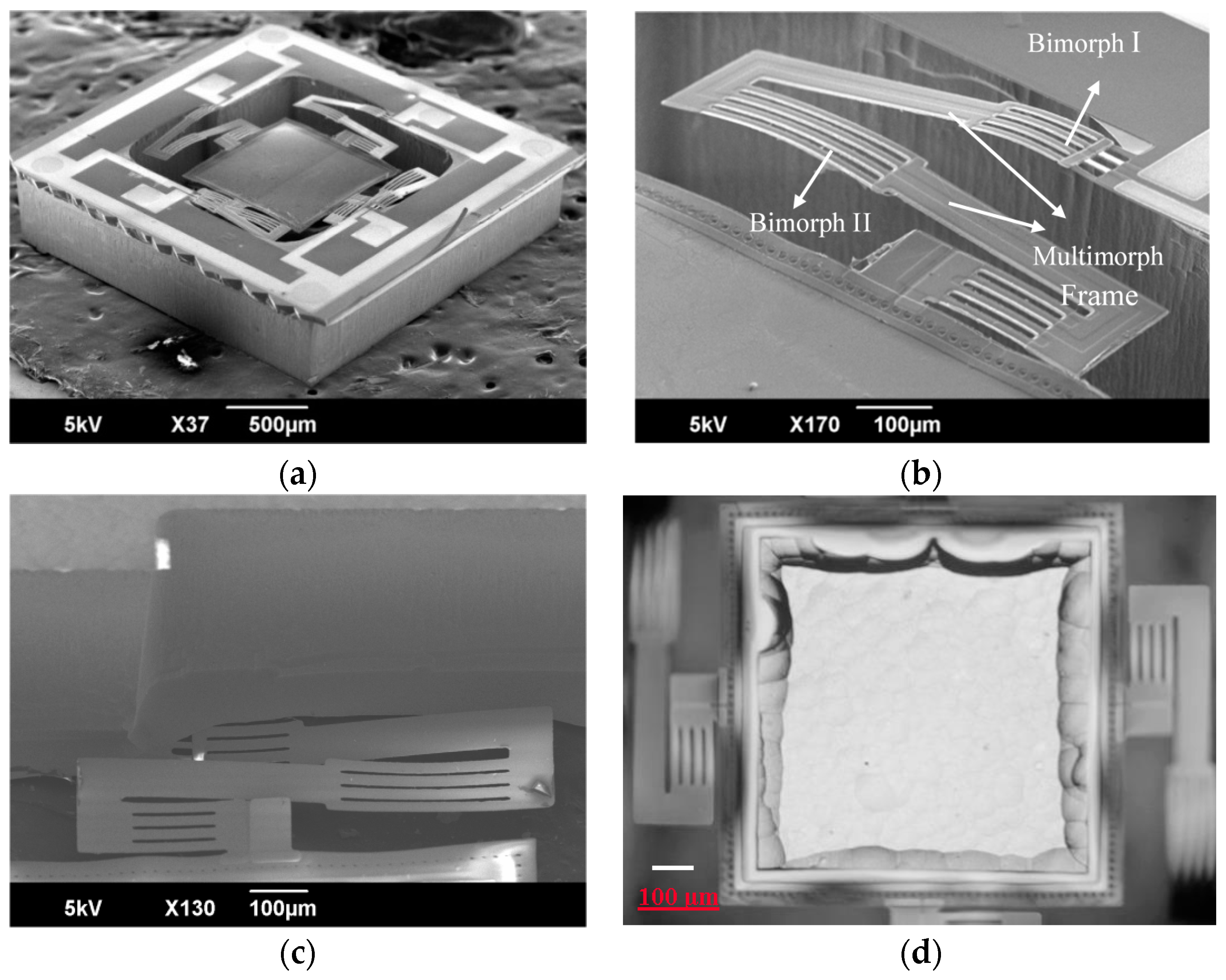
3. Design of the Cu/W LSF-Based MEMS Mirror

A tip-tilt-piston MEMS mirror has been built based on the proposed Cu/W LSF actuator design. The schematic of the MEMS mirror design is shown in Figure 3a. The central mirror plate is suspended by four Cu/W LSF actuators on four sides with connections all at the middle points. The arrangement of the actuators also helps cancel the angular tilt of the actuators. The mirror plate is made of a 25-μm-thick silicon layer for optical flatness and its surface is coated with a 0.2-μm-thick Al layer for high reflectance in broadband. The size of the mirror plate is 0.9 mm × 0.9 mm. A set of SiO2 beams is placed between the Cu/W LSF actuators and the mirror plate for thermal isolation, preventing the mirror plate from being heated. Similarly, thermal isolation bridges are also placed between the Cu/W LSF actuators and the Si substrate, reducing the heat flowing from the bimorph actuator to the substrate. The schematic of the embedded W heater with the indicator of the current flow is shown in Figure 3b. Since all four LSF actuators can be excited individually, the mirror can perform both piston scan and tip-tilt scan. When the same voltage is applied to the four actuators simultaneously, the mirror plate moves vertically, i.e., piston scanning. When only one actuator has a voltage applied to it or two opposing actuators have different voltages applied to them, the mirror plate tips or tilts.
Figure 3. Schematic of (a) the MEMS mirror based on Cu/W LSF actuator and (b) the embedded W heater.
Micromachines 06 01460 g003
The dimensions of the designed MEMS mirror using Cu/W LSF actuators are listed in Table 2. As shown in Table 2, the Cu and W thicknesses are 1 and 0.7 μm based on maximum vertical displacement optimization [16], so the effective Young’s modulus of the Cu/W bimorph Eb is equal to (ECu × tCu + EW × tW)/(tCu + tW) = 245.7 GPa, which is 3.4 times that of the Al/SiO2 bimorph (~70 GPa). Similarly, the effective Young’s modulus of the Cu/W/Cu multimorph frame Em is 202.9 GPa. COMSOL has been used to evaluate the stiffness and resonance modes, and all the layers including the bimorph and dielectric layers are considered. As shown in Figure 4, the piston and tip-tilt mode resonances are at f1 = 535 Hz and f2 = 934 Hz, respectively. By spring-mass approximation, the z-axis stiffness of one Cu/W LSF actuator kACT = [mplate × (2πf1)2]/4 = 0.123 N/m.
From the analysis in Section 2.2, the multimorph frames may have a certain curvature due to the non-ideal symmetrical layer setting from fabrication variations, so the lateral shift may not be fully compensated and the vertical displacement will be decreased. For the designed structure parameters, based on Equations (6) and (7), the corresponding maximum lateral shift and vertical displacement cause by the non-ideal symmetrical layer setting (γ ≠ 0) are shown in Figure 5. When γ ≠ 0 the lateral shift will not be ideally canceled and the vertical displacement will be decreased. The non-zero lateral shift at each tip of the four actuators will result in an in-plane rotation of the mirror plate.
Table 2. Design parameters of the Cu/W LSF MEMS mirror.
Structure ParameterValue
Device footprint2.5 mm × 2.5 mm
Mirror plate size0.9 mm × 0.9 mm
Length of Bimorph I, III150 μm
Length of Multimorph Frame 450 μm
Width of Bimorphs12 μm × 4
Width of Multimorph Frame70 μm
Thickness of Cu1 μm
Thickness of W0.7 μm
Thickness of protection SiO20.2 μm
Figure 4. Modal simulation results of the Cu/W LSF MEMS mirror using COMSOL. (a) First piston mode, the resonance is 535 Hz; (b) Second tip-tilt mode, the resonance is 934 Hz.
Micromachines 06 01460 g004
Figure 5. Calculation results of (a) maximum lateral shift and (b) vertical displacement versus the arc angle of the multimorph frame γ at different average temperature changes of the bimorphs I/II/III.
Micromachines 06 01460 g005

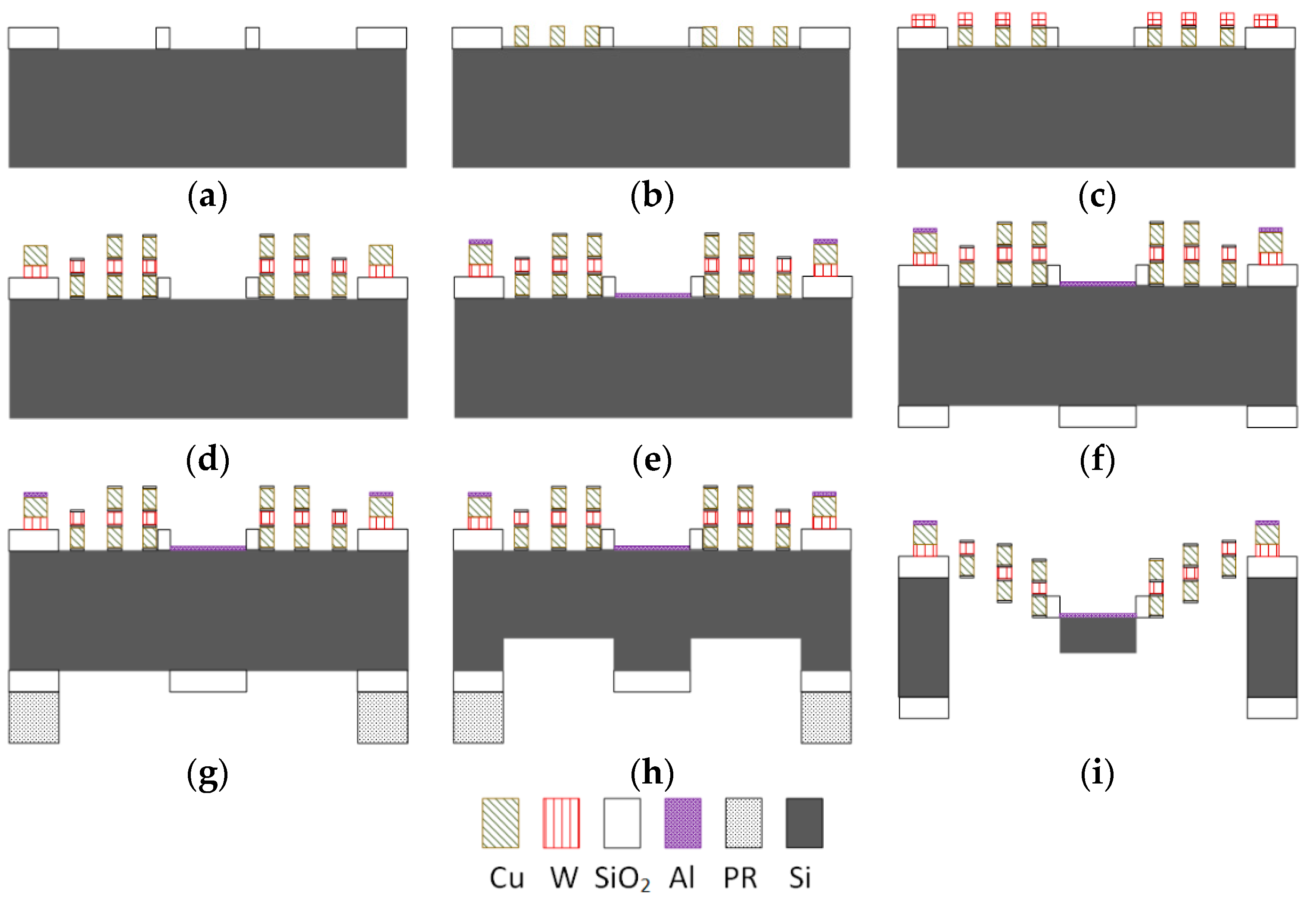
4. Fabrication Process

The device is fabricated using a combined surface and bulk micromachining process. The fabrication process is illustrated in Figure 6, which shows the cross-section view along the y-axis (as shown in Figure 3). The process starts from the front side. (a) First, 1 μm plasma-enhanced-chemical vapor-deposition (PECVD) SiO2 is deposited and buffered-oxide-etch (BOE) is used to form electrical isolation between the substrate and the thermal isolation bridges. (b) A SiO2/SiN (0.2 μm/0.05 μm) protection layer is deposited and followed by a 1 μm Cu layer (Cu-1) for sputtering and lift-off of the multimorph frames and one of the active bimorph layers. The protection layer is formed to prevent the Cu from oxidation. This layer and the other protection layers are indeed included in the FEM modeling shown in Figure 4. (c) A 0.1 μm SiN electrical isolation layer is deposited and followed by a 0.7 μm W for sputtering and lift-off of the multimorph frames and the other active bimorph layer. Another electrical isolation SiN layer is deposited on top of the W layer and then rective-ion-etching (RIE) is performed to form electrical contact openings. (d) The second Cu layer (Cu-2) is then sputtered and lifted-off to form the Cu-W-Cu multimorph frames, followed by a SiN/SiO2 (0.05 μm/0.2 μm) passivation layer deposited on top of Cu-2. Thus, a symmetrical multimorph structure of SiO2-SiN-Cu-SiN-W-SiN-Cu-SiN-SiO2 is formed, which is stress-balanced and insensitive to temperature change. (e) The dielectric layers between the actuator beams are etched for later structural release and then the sputtering and lift-off of a 0.2 μm Al layer is performed to form the mirror surface and bonding pads. After this, the process turns to the backside. (f) A 0.5 μm PECVD SiO2 is deposited and patterned to form the backside opening areas of the LSF actuator regions, to establish an etch delay between the backside chamber and the mirror plate regions. (g) A 7-μm-thick photoresist (PR) layer is spun and patterned for the backside chamber, and thus the two backside hard masks are formed together before the forming of Si depth difference. The thick PR layer will serve as both the etching mask for the backside chamber and the removal of the central SiO2. (h) A Si anisotropic DRIE is done first to form a 25-μm-deep trench in the actuator regions. (i) The SiO2 on the mirror plate region is removed by RIE and the Si anisotropic DRIE is continued all the way down to remove all the Si underneath the LSF actuators. At this point, both the mirror plate and the LSF actuators are completely released. The dicing trenches between devices are defined and DRIE-etched the same as the bimorph regions; thus, the wafer is diced into dies after (i). From (g) to (i) the process wafer is glued to the carrier wafer using thermal release tape and is not exposed in the reaction chamber of the etching. Compared with the prior front-side release processes reported in [8,9], the backside release can keep the front-side structures intact during the release and ensure a better mirror surface quality.
Scanning-electron-microscope (SEM) pictures of a fabricated device are shown in Figure 7a–c and one optical microscope picture of the backside of the mirror plate is shown in Figure 7d. The device footprint is 2.5 mm by 2.5 mm. An initial displacement of about 130 μm below the substrate occurs after the structural release due to the residual stresses-induced curvature of the bimorphs. The symmetric multimorph frames show a negligible curvature and the thin-film stresses are well balanced. The close-up view from the backside in Figure 7c shows the Si underneath the LSF actuator is fully removed. Figure 7d shows the backside of the mirror plate, where the Si layer is not completely flat due to the non-uniformity of DRIE. This problem can be avoided by using SOI wafers and using the buried oxide layer as the DRIE etching stop.
Figure 6. Fabrication process of the Cu/W-based LSF MEMS mirror. (a) SiO2 deposition and wet etch; (b) Cu-1 sputtering and lift-off; (c) W sputtering and lift-off; (d) Cu-2 sputtering and lift-off; (e) Al sputtering and lift-off; (f) Backside SiO2 deposition and patterning; (g) Backside PR patterning; (h) Backside DRIE to certain depth; (i) Backside DRIE to remove all Si under.
Micromachines 06 01460 g006
Figure 7. SEM/microscope pictures of the fabricated Cu-W LSF-based MEMS mirror. (a) Whole device; (b) Close view of LSF actuator from front-side; (c) Close view of LSF actuator from backside; (d) Optical microscope picture of the backside of the mirror plate.
Micromachines 06 01460 g007

5. Experiment Results and Analysis

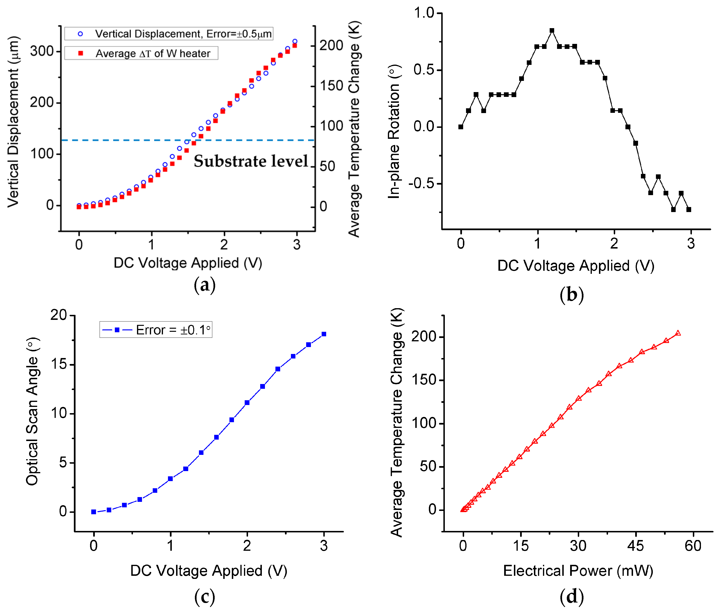
5.1. Static Response

The static responses of both piston and angular rotation modes have been experimentally characterized. The vertical displacement and lateral shift are measured using an Olympus BX51 microscope (Olympus, Tokyo, Japan) with a QC200 Digital Readouts Systems (Heidenhain, Traunreut, Germany). By applying a direct current (DC) voltage on all LSF actuators simultaneously, a piston motion of the mirror plate can be achieved. The displacement can be precisely measured by tracking a selected point on the mirror surface. As shown in Figure 7a, a maximum displacement of 320 μm has been achieved at only 3 V input voltage. Also, since the resistivity of W and thus the resistance of the W heater vary with temperature, the average temperature change across the LSF actuator can be monitored by tracking the resistance change of the W heater. The temperature coefficient of resistivity (TCR) of the fabricated W heater is first measured using a temperature-controlled oven, and the measured TCR is 0.00156/K. Figure 7a also shows the calculated average temperature change versus the applied DC voltage, where the corresponding vertical displacements of temperature changes of 50, 100, 150 and 200 K are about 87, 172, 225 and 312 μm, respectively; these agree with the calculation results in Figure 5b for the case of γ = 0 with errors within 13%. Figure 7b shows the in-plane tilt of the mirror plate, where the maximum in-plane rotation is about 0.85°. Figure 7c shows the optical scan angle change with input DC voltage, which is measured by applying voltage on only one of the LSF actuators, and other actuators are held at 0 V. A mechanical tilt of the mirror plate will be generated. The corresponding optical scan angle is twice of the mechanical tilt angle. The maximum optical scan angle reaches about 18° at 3 V. The power consumption of one Cu/W LSF actuator is 56 mW at 3 V, which yields the responsivities of the piston mode and angular mode to be 0.7 mW/μm (four actuators) and 3.1 mW/°(mW per degree, one actuator), respectively. Furthermore, 56 mW is also the maximum power the actuators can handle since 3 V is the maximum voltage for the actuators.
In addition, by following the equivalent thermal circuit model [20], i.e., ΔT = PElectrical × RT, the average effective thermal resistance RT is estimated from Figure 8d to be about 3.9 K/mW, which is the average slope of the ΔT-PElectrical curve in Figure 8d. The thermal resistance mainly contains two types: (1) the thermal conduction resistance through solid structures to substrate or mirror plate and (2) the thermal conduction and convection resistance between the heated actuator and air. As shown in Figure 8d, the effective thermal resistance decreases with the increasing actuator temperature, which indicates the heat transfer coefficient h between the heated actuator and surrounding air is not constant and increases slightly with the rise of the temperature [21]. For the device level thermal modeling and the effect of thermal convection and radiation, additional study needs to be done in the future.

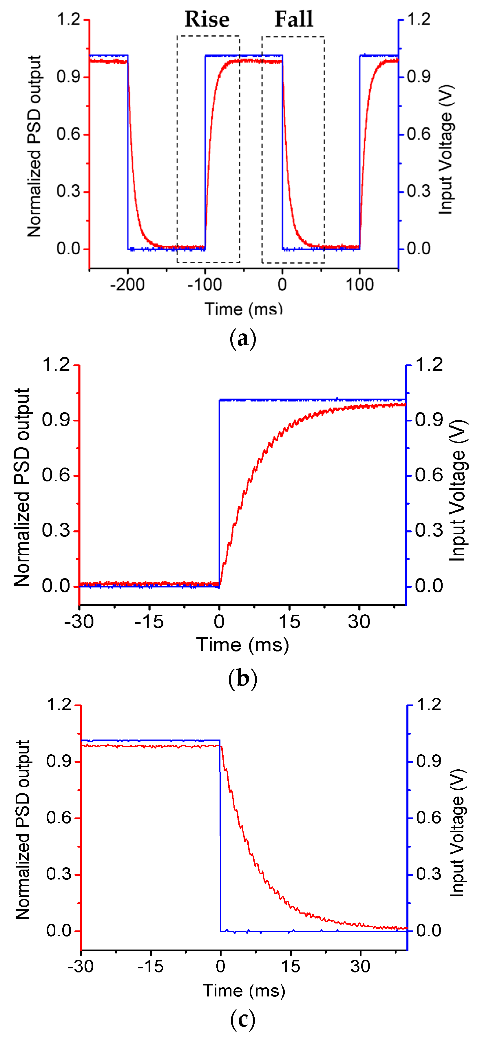
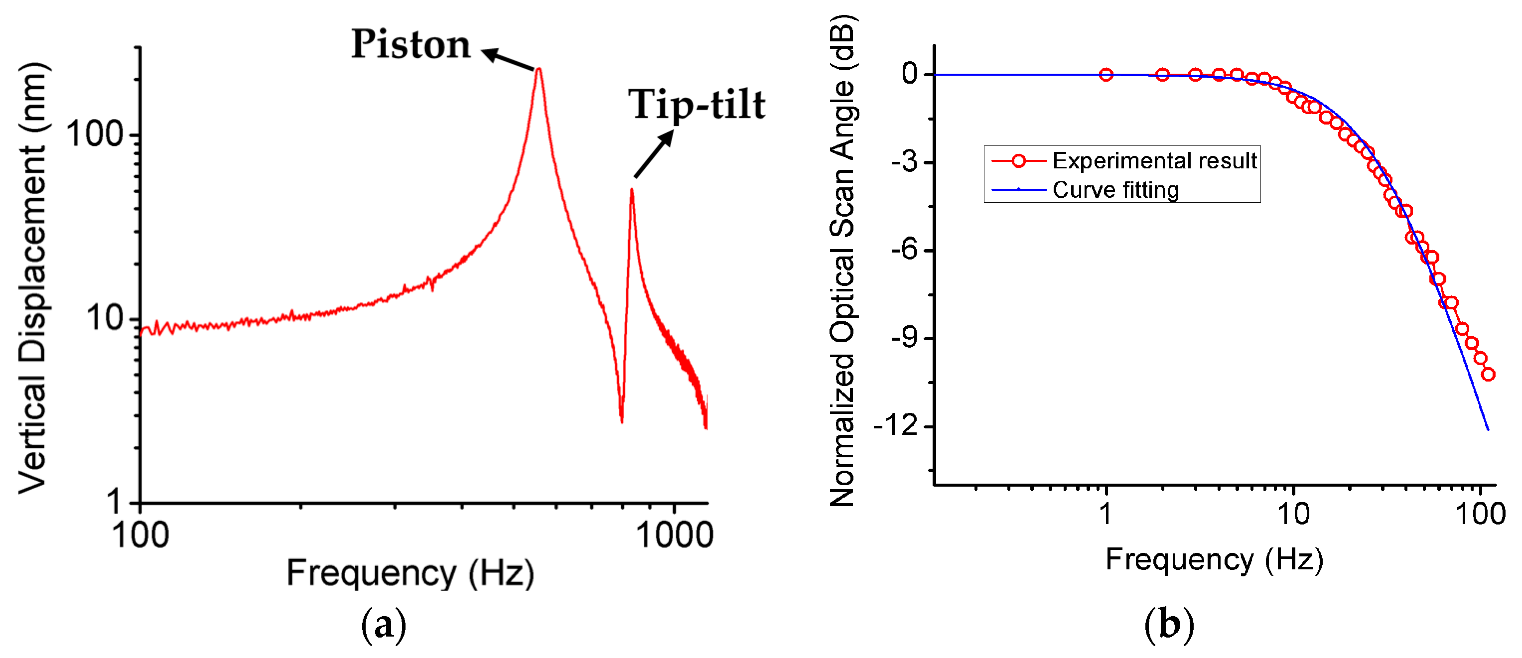
5.2. Dynamic Response

The dynamic responses of the MEMS mirror including the step response and frequency response have been thoroughly characterized. To measure the step response, a laser beam points to the mirror plate and a photosensitive detector (PSD) is used to monitor the position of the reflected laser beam. A square wave is applied to one of the actuators and the response is shown in Figure 9a, with the close-up views of the rise and fall response shown in Figure 9b,c. The rise time (10% to 90%) is 15.4 ms and the fall time (90% to 10%) is 16.1 ms, where a difference of 0.7 ms is observed. This difference is believed to be from the back-flow heating effect from the mirror plate, which is regarded as a large thermal capacitor. Thus, the response speed will be also limited by the fall time, which is the cooling-down process.
Figure 8. Static responses of the fabricated MEMS mirror. (a) Vertical displacement and average temperature change versus applied DC voltage; (b) In-plane rotation of the mirror plate versus applied DC voltage; (c) Optical scan angle versus applied DC voltage by actuating one actuator; (d) Average temperature change versus input electrical power.
Micromachines 06 01460 g008
The frequency response of the MEMS mirror was measured by a Polytec OFV-511 Laser Doppler Vibrometer (LDV) (Polytec, Dexter, MI, USA). The applied voltage was (1 + 0.2sinωt) V on four actuators. The response curve is plotted in Figure 10a, where the first piston mode is 550 Hz and the second tip-tilt mode resonance is 832 Hz, which have the respective differences of +3% and −11% compared to the simulation result shown in Figure 4b. It is interesting to note that the first mode (piston) shifts to a higher frequency while the second mode (rotation) shifts to a lower frequency. This discrepancy is believed to come from the non-uniformly etched Si underneath the mirror plate as shown in Figure 7d, where the silicon of the mirror plate is undercut seriously from all four edges, i.e., for the same mass, the moment of inertia of the mirror plate is reduced. Thus, rotational modes would have decreased resonance frequencies when piston modes had almost no change.
Figure 9. (a) Step response of the MEMS mirror; (b) Zoom-in picture of the rise time (heating up); (c) Zoom-in picture of the fall time (cooling down).
Micromachines 06 01460 g009
At low frequency, the environmental noises greatly affect the accuracy of the LDV measurement, so the frequency response at low frequency was measured by using optical beam steering. The optical scan angle is measured by pointing a laser beam perpendicular to the mirror plate through a screen with a pinhole for the laser to pass. The optical scan angle is calculated based on the transverse scan range on the screen and the distance between the micromirror and the screen. The response curve is plotted in Figure 10b, where the applied voltage was (3 + 3sinωt) V to one of the LSF actuators to measure the actuation amplitude of the Cu/W LSF bimorph actuator at low frequency range. The low frequency band is dominated by thermal and the −3 dB thermal cutoff frequency of the bimorph actuators is about 27 Hz. From the curve fitting using first-order low-pass resistor-capacitor (RC) circuit, the corresponding thermal constant is τ = 5.65 ms.
Figure 10. (a) Frequency response of the vertical displacement from 100 to 2000 Hz; (b) Frequency response of the scan angle from 0.1 to 100 Hz, the experimental result is fitted using first-order low-pass RC circuit, time constant τ = RC = 5.65 ms.
Micromachines 06 01460 g010
The stiffness of one Cu/W LSF actuator can be calculated from kACT = [mp × (2πf1)2]/4, where mp is the mass of the mirror plate and f1 is the first piston resonant frequency shown in Figure 10a. The calculated kACT is about 0.13 N/m. Thus, according to Hooke’s law, the maximum electrothermal force that can be generated by one Cu/W LSF actuator is about 44.5×10⁻⁶ N . Therefore, coupled with its large scan range, this new Cu/W LSF actuator is suitable for applications where both large range and large force are desired [22,23]. For the thermal mechanical noise, the root mean square (RMS) noise displacement of the Cu/W LSF actuator is given by z n = k B T k A C T [24], where kB is the Boltzmann constant and T is the temperature of the actuator. For the maximum average temperature change of 200 K, zn is about 0.24 nm, which can be neglected compared with the actuation range of the actuator.
From Figure 8d, the estimated average effective thermal resistance RT is about 3.9 K/mW. The total thermal capacitance of the Cu/W-based LSF actuator is approximately given by CLSF = CCu + CW + CSiO2 + CSiN = 1.6 μJ/K. Thus, the calculated thermal time constant τ = RTCLSF ≈ 6.2 ms. The corresponding calculated rise time and −3 dB thermal cutoff frequency are respectively 13.6 ms and 25.7 Hz, corresponding to 11.7% and 4.8% errors, respectively, compared with the experimental results. In contrast, for the Cu/W-based LSF actuator with the same structures but with a 25-μm-thick Si underneath the frame, an extra thermal capacitance of about 4.1 μJ/K will be introduced, resulting in a rise time of 49.7 ms and a −3 dB thermal cutoff frequency of 7 Hz. Therefore, by removing the 25-μm-thick Si layer under the frames, the response speed of the new multimorph frame design is 3.6 times faster and the difference between the rise and fall time is also reduced.

6. Conclusions

A large-range, fast-response electrothermal tip-tilt-piston MEMS mirror based on a new Cu/W lateral-shift-free (LSF) thermal bimorph actuator design has been successfully demonstrated. A symmetric Cu/W/Cu thin-film frame has been employed to replace the thick silicon frame and achieved fast thermal response. W has been employed as both one of the bimorph materials and the embedded heater. A backside release process has been developed to keep the mirror plate intact during release and fully remove all the Si underneath the Cu/W LSF actuators. The MEMS mirror can perform both piston and tip-tilt motions. A static piston displacement up to 320 μm and an angular optical scan of ±18° have been achieved with a voltage of only 3 V. Thermal response is 3.5 times faster with the proper material selection and structure optimization, and the mechanical stiffness of the LSF actuator is greater than those of previous Al/SiO2 bimorph designs attributed to the large Young’s moduli of both Cu and W. The combination of large range, high force and fast response with small driving voltage makes this novel Cu/W LSF actuator very suitable for various optical imaging, laser tracking, and ranging applications.

Acknowledgments

This work was partially supported by the National Science Foundation under award #1512531 and #1514154 and the University of Florida Opportunity Seed Fund. Device fabrication was done in the Nanoscale Research Facility of the University of Florida.

Author Contributions

Xiaoyang Zhang conceived, designed and performed the experiments, analyzed the data and wrote the paper. Liang Zhou helped perform the experiments for device characterizations. Huikai Xie conceived and supervised the design and the experiments and revised the paper critically.

Conflicts of Interest

The authors declare no conflict of interest.

References

  1. Manzardo, O.; Herzig, H.P.; Marxer, C.R.; de Rooij, N.F. Miniaturized time-scanning Fourier transform spectrometer based on silicon technology. Opt. Lett. 1999, 24, 1705–1707. [Google Scholar] [CrossRef] [PubMed]
  2. Wu, L.; Pais, A.; Samuelson, S.R.; Guo, S.; Xie, H. A mirror-tilt-insensitive Fourier transform spectrometer based on a large vertical displacement micromirror with dual reflective surface. In Proceedings of the 15th IEEE International Conference on Solid-State Sensors, Actuators and Microsystems (Transducers ’09), Denver, CO, USA, 21–25 June 2009.
  3. Liu, L.; Wang, E.; Zhang, X.; Liang, W.; Li, X.; Xie, H. MEMS-based 3D confocal scanning microendoscope using MEMS scanners for both lateral and axial scan. Sens. Actuators A Phys. 2014, 215, 89–95. [Google Scholar] [CrossRef] [PubMed]
  4. Liu, X.M.; Cobb, M.J.; Chen, Y.C.; Kimmey, M.B.; Li, X.D. Rapid-scanning forward-imaging miniature endoscope for real-time optical coherence tomography. Opt. Lett. 2004, 29, 1763–1765. [Google Scholar] [CrossRef] [PubMed]
  5. Sun, J.; Guo, S.; Wu, L.; Liu, L.; Choe, S.-W.; Sorg, B.S.; Xie, H. 3D in vivo optical coherence tomography based on a low-voltage, large-scan-range 2D MEMS mirror. Opt. Express 2010, 18, 12065–12075. [Google Scholar] [CrossRef] [PubMed]
  6. Toshiyoshi, H.; Fujita, H. Electrostatic micro torsion mirrors for an optical switch matrix. J. Microelectromech. Syst. 1996, 5, 231–237. [Google Scholar] [CrossRef]
  7. Van Kessel, P.F.; Hornbeck, L.J.; Meier, R.E.; Douglass, M.R. A MEMS-based projection display. Proc. IEEE 1998, 86, 1687–1704. [Google Scholar] [CrossRef]
  8. Wang, W.; Chen, J.; Zivkovic, A.S.; Duan, C.; Xie, H. A silicon based Fourier transform spectrometer based on an open-loop controlled electrothermal MEMS mirror. In Proceedings of the 18th IEEE International Conference on Solid-State Sensors, Actuators and Microsystems (Transducers ’15), Anchorage, AK, USA, 21–25 June 2015.
  9. Wu, L.; Xie, H. A large vertical displacement electrothermal bimorph microactuator with very small lateral shift. Sens. Actuators A Phys. 2008, 145, 371–379. [Google Scholar] [CrossRef]
  10. Jain, A.; Kopa, A.; Pan, Y.; Feeder, G.K.; Xie, H. A two-axis electrothermal micromirror for endoscopic optical coherence tomography. IEEE J. Sel. Top. Quantum Electron. 2004, 10, 636–642. [Google Scholar] [CrossRef]
  11. Hao, Z.; Wingfield, B.; Whitley, M.; Brooks, J.; Hammer, J.A. A design methodology for a bulk-micromachined two-dimensional electrostatic torsion micromirror. J. Microelectromech. Syst. 2003, 12, 692–701. [Google Scholar]
  12. Sandner, T.; Grasshoff, T.; Schenk, H.; Kenda, A. Out-of-Plane Translatory MEMS actuator with extraordinary large stroke for optical path length modulation. Proc. SPIE MOEMS Miniat. Syst. X 2011, 7930, 79300I. [Google Scholar]
  13. Zhu, Y.; Liu, W.; Jia, K.; Liao, W.; Xie, H. A piezoelectric unimorph actuator based tip-tilt-piston micromirror with high fill factor and small tilt and lateral shift. Sens. Actuators A Phys. 2011, 67, 495–501. [Google Scholar] [CrossRef]
  14. Zhang, X.; Zhang, R.; Koppal, S.; Butler, L.; Cheng, X.; Xie, H. MEMS mirror submerged in liquid for wide-angle scanning. In Proceedings of the 18th IEEE International Conference on Solid-State Sensors, Actuators and Microsystems (Transducers ’15), Anchorage, AK, USA, 21–25 June 2015.
  15. Garcia, E.; Lobontiu, N. Induced-strain multimorphs for microscale sensory actuation design. Smart Mater. Struct. 2004, 13, 725–732. [Google Scholar] [CrossRef]
  16. Chu, W.H.; Mehregany, M.; Mullen, R.L. Analysis of tip deflection and force of a bimetallic cantilever microactuator. J. Micromech. Microeng. 1993, 6, 4–7. [Google Scholar] [CrossRef]
  17. Ali, S.Z.; Udrea, F.; Milne, W.I.; Gardner, J.W.; Member, S. Tungsten-based SOI microhotplates for smart gas sensors. J. Microelectromech. Syst. 2008, 17, 1408–1417. [Google Scholar] [CrossRef]
  18. Ghodssi, R.; Lin, P. MEMS Materials and Processes Handbook; Springer: Berlin, Germany, 2011. [Google Scholar]
  19. Pal, S.; Xie, H. Fabrication of robust electrothermal MEMS devices using aluminum-tungsten bimorphs and polyimide thermal isolation. J. Micromech. Microeng. 2012, 22, 115036–115049. [Google Scholar] [CrossRef]
  20. Todd, S.T.; Xie, H. An electrothermomechanical lumped element model of an electrothermal bimorph actuator. J. Microelectromech. Syst. 2008, 17, 213–225. [Google Scholar] [CrossRef]
  21. Pike, A.; Gardner, J.W. Thermal modelling and characterisation of micropower chemoresistive silicon sensors. Sens. Actuators B Chem. 1997, 45, 19–26. [Google Scholar] [CrossRef]
  22. Zhang, X.; Duan, C.; Liu, L.; Li, X.; Xie, H. A non-resonant fiber scanner based on an electrothermally-actuated MEMS stage. Sens. Actuators A Phys. 2015, 233, 239–245. [Google Scholar] [CrossRef] [PubMed]
  23. Wu, L.; Xie, H. A millimeter-tunable-range microlens for endoscopic biomedical imaging applications. IEEE J. Quantum Electron. 2010, 46, 1237–1244. [Google Scholar] [CrossRef]
  24. Yang, B.; Wang, S.; Li, H.; Zhou, B. Mechanical-thermal noise in drive-mode of a silicon microgyroscope. Sensors 2009, 9, 3357–3375. [Google Scholar] [CrossRef] [PubMed]

