
Digital Microfluidic System with Vertical Functionality

1
Department of Bioengineering, University of California, Los Angeles, CA 90095, USA
2
Department of Chemistry & Biochemistry, University of California, Los Angeles, CA 90095, USA
*
Author to whom correspondence should be addressed.
Micromachines 2015, 6(11), 1655-1674; https://doi.org/10.3390/mi6111448
Submission received: 1 September 2015
/
Revised: 19 October 2015
/
Accepted: 27 October 2015
/
Published: 4 November 2015
(This article belongs to the Special Issue Droplet Microfluidics: Techniques and Technologies)
Abstract
:Digital (droplet) microfluidics (DµF) is a powerful platform for automated lab-on-a-chip procedures, ranging from quantitative bioassays such as RT-qPCR to complete mammalian cell culturing. The simple MEMS processing protocols typically employed to fabricate DµF devices limit their functionality to two dimensions, and hence constrain the applications for which these devices can be used. This paper describes the integration of vertical functionality into a DµF platform by stacking two planar digital microfluidic devices, altering the electrode fabrication process, and incorporating channels for reversibly translating droplets between layers. Vertical droplet movement was modeled to advance the device design, and three applications that were previously unachievable using a conventional format are demonstrated: (1) solutions of calcium dichloride and sodium alginate were vertically mixed to produce a hydrogel with a radially symmetric gradient in crosslink density; (2) a calcium alginate hydrogel was formed within the through-well to create a particle sieve for filtering suspensions passed from one layer to the next; and (3) a cell spheroid formed using an on-chip hanging-drop was retrieved for use in downstream processing. The general capability of vertically delivering droplets between multiple stacked levels represents a processing innovation that increases DµF functionality and has many potential applications.
Keywords:
digital microfluidics; EWOD; vertical functionality; hydrogel; sieve; spheroid; embryoid body
1. Introduction
Digital (droplet) microfluidics (DµF) allows the dispensing, splitting, mixing, and translation of nanoliter- to microliter-sized droplets of liquid on a two-dimensional (2D) array of electrodes [1,2]. By applying a voltage across dielectric-coated electrodes, a combination of electrostatic and dielectrophoretic (DEP) forces enables these basic liquid handling steps [1,3]. As the benefits and processing capabilities of the DµF platform have grown, the range of lab-on-a-chip applications in chemistry, biology, and medicine has expanded [4]. Notable benefits include reduced reaction times and reagent consumption on the microscale [5,6], the lack of pumps or valves [7], reconfigurability [8], and automation [9].
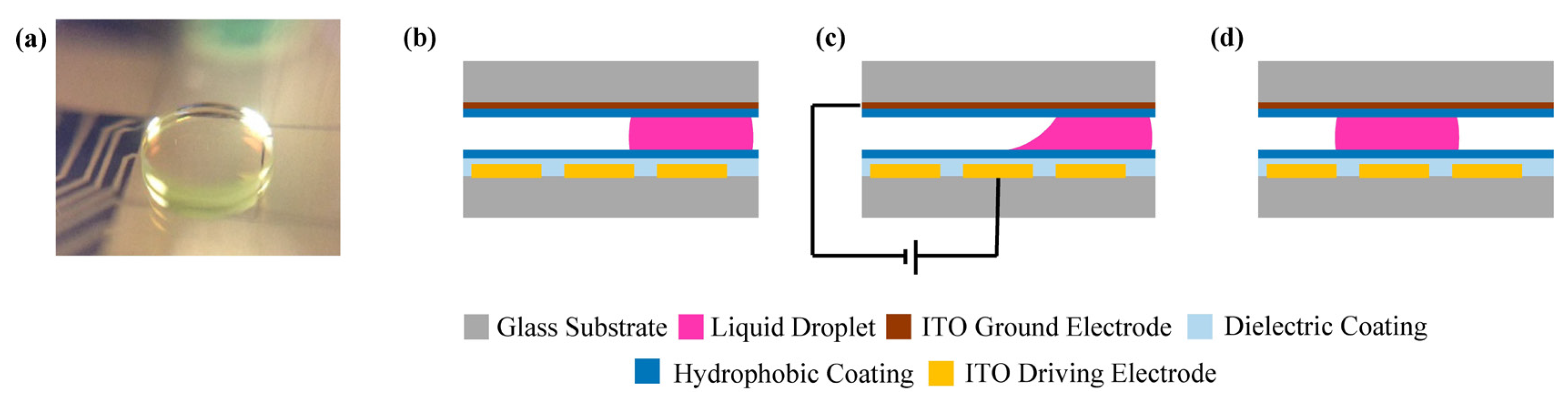
DµF devices are fabricated with a planar array of electrodes for actuating the droplets. The fabrication process typically involves patterning conductive electrodes using standard photolithography techniques. Thin films of dielectric materials and hydrophobic coatings are also deposited to prevent electrolysis and establish non-wetting conditions. Discrete liquid droplets are created or inserted between the two plates that incorporate dielectric-coated driving electrodes and a ground electrode (Figure 1). To move the droplets, an electrical potential is applied to electrodes adjacent to the target liquid droplet. The resulting electromechanical force drives droplet translation through a combination of electrowetting and dielectrophoretic (DEP) mechanisms, depending on the liquid and the applied frequency [8,10,11]. Translation by electrowetting can be analyzed in terms of an electrostatic force, a surface tension force, and a pressure force [8]. Dielectrophoretic actuation is a consequence of polarization in the liquid droplet due to non-uniform fields that develop in the liquid and the ambient medium. DEP forces act at the two-fluid interface, at the tri-phase contact line, and in the bulk of the droplet [12]. The electrode shape and position dictate where droplets can be moved and the types of operations that can be performed [12]. In this format droplets can only be moved laterally, which limits the potential applications.
Figure 1.
(a) Oblique image of a 1 µL droplet sandwiched between a gold driving electrode and a transparent top plate; (b) side schematic of a droplet in a standard digital (droplet) microfluidics (DµF) configuration with layers indicated by color; (c) by applying a voltage across adjacent electrodes, electrowetting and dielectrophoretic forces drive droplet translation; and (d) position the droplet over the actuated electrode.
To improve the functionality of DµF systems, several innovative device designs have been developed to interface the planar droplet system with the external environment or circumvent the two-dimension constraint. Abdelgawad et al. developed a method to transfer a liquid droplet from a DµF configuration into a channel-based microfluidic system [13]. Their design makes it possible to combine the higher throughput characteristic of channel-based systems with the reconfigurability of DµF. Wang and Jones extended this work and accomplished the reverse: establishing the conditions for reversibly transitioning between closed and open DµF configurations [14]. A design by Ren et al. used an external syringe pump to introduce discrete droplets into a DµF system, obviating the need to manually replenish reservoirs [15]. Bhargava et al. created a modular design for assembling three-dimensional (3D) channel-based microfluidic systems that enables vertical channel assembly [16]. The use of novel substrate materials has enabled fabrication of flexible DµF devices [17]; in this work, the droplets had still been restricted to lateral movement in the device. To date, there are no DµF designs that permit vertical movement between planes or layers in the device.
A major application of DµF is as a platform for biological assays and cell manipulation [3,18,19,20,21,22,23,24,25,26,27,28,29,30,31,32]. Technological advances that have enabled these applications have included improvements to automated proteomics [9,23,33], DEP-based protein and cell sorting [34,35,36], complete mammalian cell culture on-chip [37], and cell spheroid development [38]. Investigations have demonstrated negligible effects to cell health during low-frequency DµF actuation using small electrodes [39]. Spatiotemporal control of tissue-engineered scaffolds has emerged as a critical tool for controlling cell behavior and directing cell fate [40,41,42,43,44,45], so it is not surprising that hydrogels have also recently been incorporated into DµF devices [18,23,24,33,46]. The mechanical properties of hydrogels, such as their elastic modulus and toughness, have been shown to correlate with cell behaviors such as extracellular matrix protein production, cell adhesion, migration, and stem cell differentiation [40,41,42,44,45,47]. Other physical properties of a hydrogel scaffold, such as porosity and crosslink density, similarly effect cellular behavior [40,41,47,48]. Additionally, temporal cues, such as the timing of growth factor delivery and mechanical stress induction, play important roles in directing stem cell differentiation [40,41,42,44,45,49]. With the aim of creating biomimetic microenvironments, researchers have shown that using hydrogels that have tailored crosslink density gradients for cell encapsulation better mimics the complex extracellular matrix and tissue gradients that exist naturally [40,41]. Thus, controlling the spatiotemporal cell microenvironment during directed cell culture is of vital importance [40,41,42,43,44,45]. For DµF to become better suited for tissue engineering applications that utilize hydrogels, good control over crosslink gradient profiles is necessary [50].
Aijian et al. recently demonstrated the use of wells created in DµF devices for 3D cell culture experiments [38]. Cell solutions were translated to the wells to form hanging drop cultures for cell spheroid creation. The DµF device was relocated to an incubator after droplet manipulation, and after 24 to 48 h, the cells naturally aggregated into spheroids that were later used as tumor models in a drug screening assay. While this platform offers a new tool for 3D tissue development for automated drug screening, the difficulty in manually retrieving the spheroid limits downstream processing capabilities. The ability to retrieve these spheroid samples would enable further experimentation on them, including hydrogel encapsulation or electric field stimulation.
In the first section below, we introduce the fabrication protocols for introducing vertical functionality and demonstrate the capability. Next, a theoretical framework for droplet translation between stacked layers is presented and used to establish design parameters for DµF devices with vertical functionality. Finally, three illustrative applications are presented that demonstrate some the new opportunities and areas of research that are enabled by this innovation in DµF.
2. Experimental Section
2.1. Experimental Design and Configuration
The electrodes were fabricated using transparent indium-tin oxide (ITO) so that droplets could be easily viewed through multiple stacked layers. The driving electrodes were 2 mm × 2 mm in size and a gap height of approximately 120 µm was used between each layer. The experiments were performed by stacking three plates, as shown in Figure 2a. These plates are referred to as the bottom, middle, and top. The bottom and middle plates contain driving electrodes and are used to translate discrete droplets of liquid during experiments. The top plate is stacked on top of the middle plate and contains no driving electrodes; it is coated with an electrically conductive ITO layer to act as a ground electrode and also with a hydrophobic Teflon-AF® layer. When describing the experiments, the gap between the bottom plate and middle plate will be referred to as the bottom layer, while the gap between the middle plate and the top plate will be referred to as the top layer.
Figure 2.
(a) Oblique schematic of the stacked design, identifying the bottom, middle, and top plates; (b) actual experiment showing full setup; and (c) cross-section schematic showing the typical two-plate fabrication process with the additional steps required for the middle plate.
Figure 2.
(a) Oblique schematic of the stacked design, identifying the bottom, middle, and top plates; (b) actual experiment showing full setup; and (c) cross-section schematic showing the typical two-plate fabrication process with the additional steps required for the middle plate.
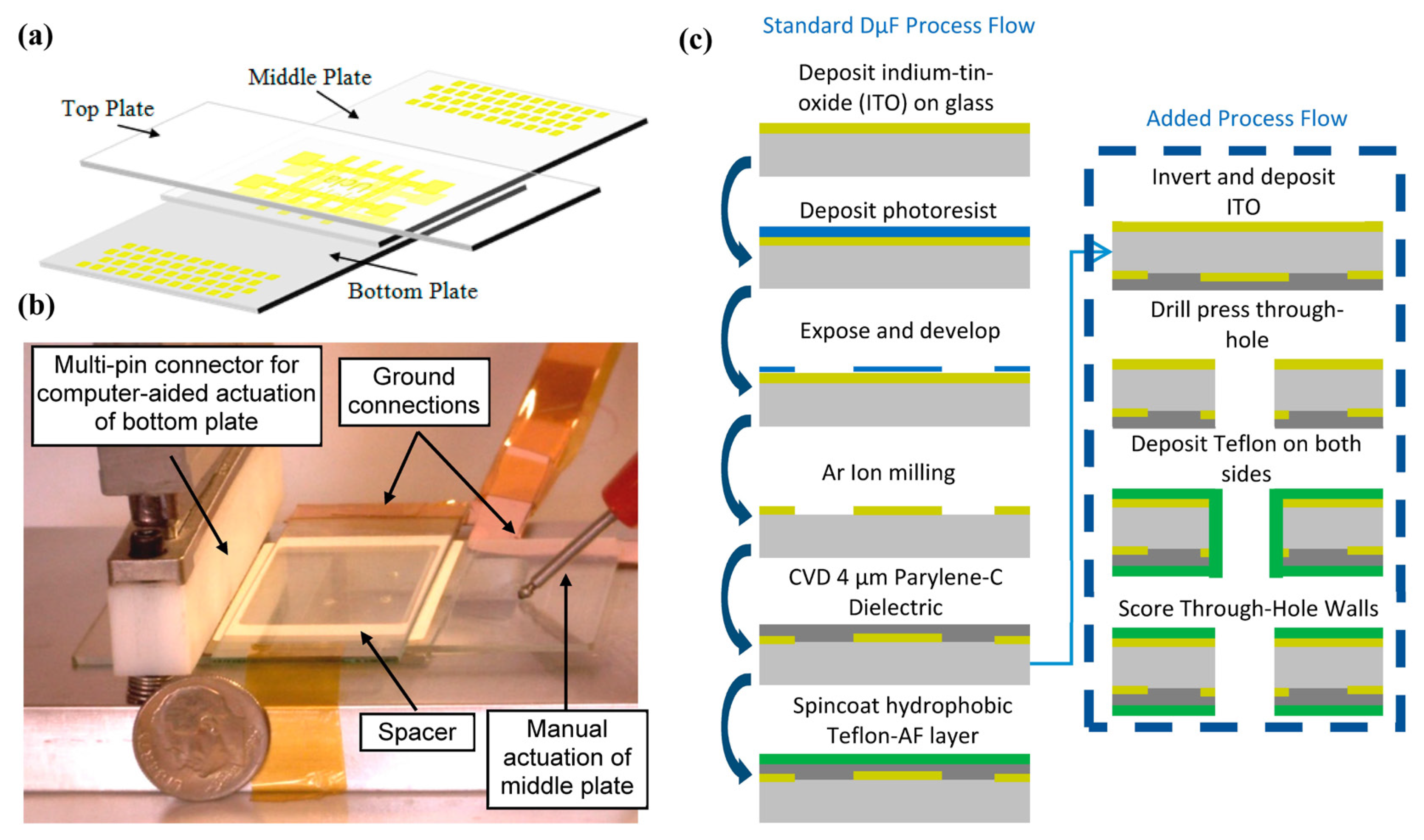
The bottom plate’s contact pads were brought in contact with a multi-pin connector attached to a laptop computer running LabView software (National Instruments, Austin, TX, USA) for bottom plate electrode actuation. The middle plate was actuated by manually touching contact pads with metal probes to actuate middle plate electrodes. Ground wires were attached to the ITO coatings on both the top plate and the underside of the middle plate. A spacer was placed between each layer with an approximate thickness of 120 μm (Figure 2b). To translate the droplet, a voltage of approximately 110 VPP at 17 kHz was applied.
2.2. Bottom DµF Plate and Top Plate Fabrication
The bottom plate was fabricated in the California NanoScience Institute (CNSI) Integrated System Nanofabrication Cleanroom (ISNC) at UCLA. The substrate consisted of a 7.5-cm long × 5-cm wide × 1-mm thick piece of soda-lime glass (LabScientific, Inc., Livingston, NJ, USA, Cat# 7787). For patterning of the driving electrodes, the substrate was sputter-coated with 100 nm of indium-tin oxide (ITO) using an Ulvac JSP 8000 (Garching, Germany). The ITO was coated with AZ5214 photoresist (spin-coated, 3000 rpm for 60 s), soft-baked on a hot plate (110 °C for 60 s), and exposed to 170 mJ of UV light under a patterned mask using a Karl Suss MA6 contact aligner (soft contact, SÜSS MicroTec, Garching, Germany). The plate was developed using diluted AZ400K Developer (5:1 deionized (DI) water to developer) for 60 s and rinsed clean with DI water. The exposed ITO was subjected to a 13.5-min argon ion milling process using an Oxford 80 Plus RIE (Oxford Instruments, Abingdon, UK, 50 mTorr, 300 V RF bias, 400 V DC bias, 40 sccm Ar flow rate) to remove the unwanted ITO. The plate was then sonicated in methanol for several minutes to remove the remaining photoresist, followed by a rinse in DI water. The contact pads were covered with Kapton tape and a dielectric layer consisting of 3.4 μm of Parylene-C was deposited via chemical vapor deposition (Specialty Coating Systems PDS 2010, Indianapolis, IN, USA). Finally, a thin Teflon-AF® film was spin-coated (2000 rpm for 60 s) and post-baked on a hot plate (110 °C for 5 min and 180 °C for 15 min) on top of the Parylene-C to provide a hydrophobic outer surface.
The top plate, an ITO-coated glass slide (Precision Glass and Optics), was coated with Teflon-AF®.
2.3. Middle DµF Plate Fabrication
The middle plate was fabricated by the same protocol as was used for the bottom plate, with the following exceptions, highlighted in Figure 2c. A 100-nm layer of ITO was sputter-coated onto the reverse side of the plate as well as the top. One surface of the substrate was patterned with actuating electrodes using the previously described methods, while the other surface was left as a continuous ITO layer. Prior to Parylene-C deposition, 1.1-mm diameter holes were drilled through the plate (1.1 mm Triple Ripple Diamond Drill Bits from GlassWarePro, Twinsburg, OH, USA, Cat# TRD116) at the center of various electrodes. After Parylene-C deposition, Teflon-AF® was deposited onto both sides of the plate using the same protocol as mentioned previously. The drilled holes were mechanically scored to remove the hydrophobic Teflon-AF® coatings on the inside walls of the holes.
2.4. DµF Experiments
2.4.1. Vertical Functionality
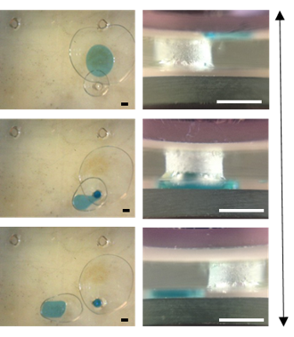
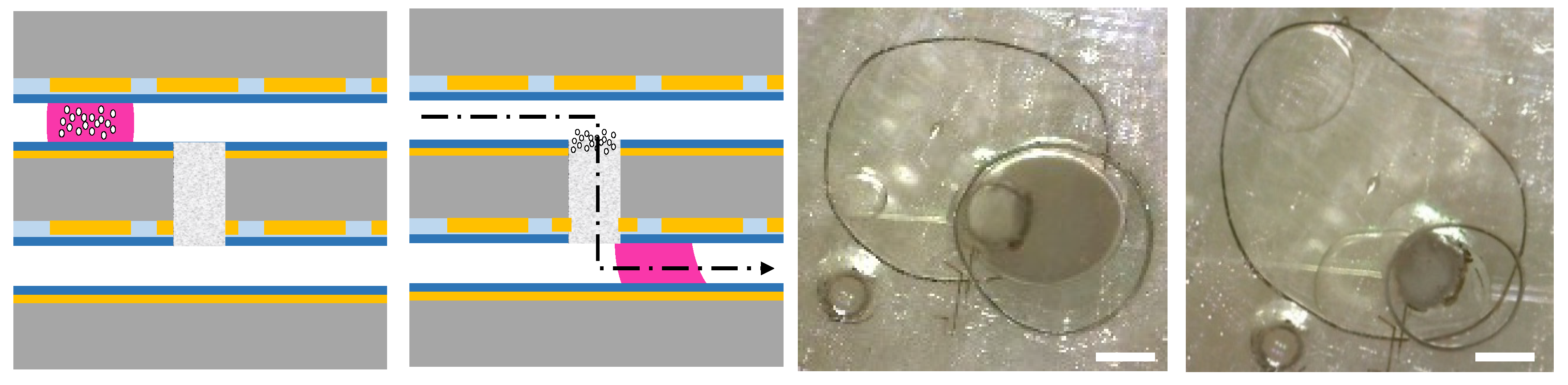
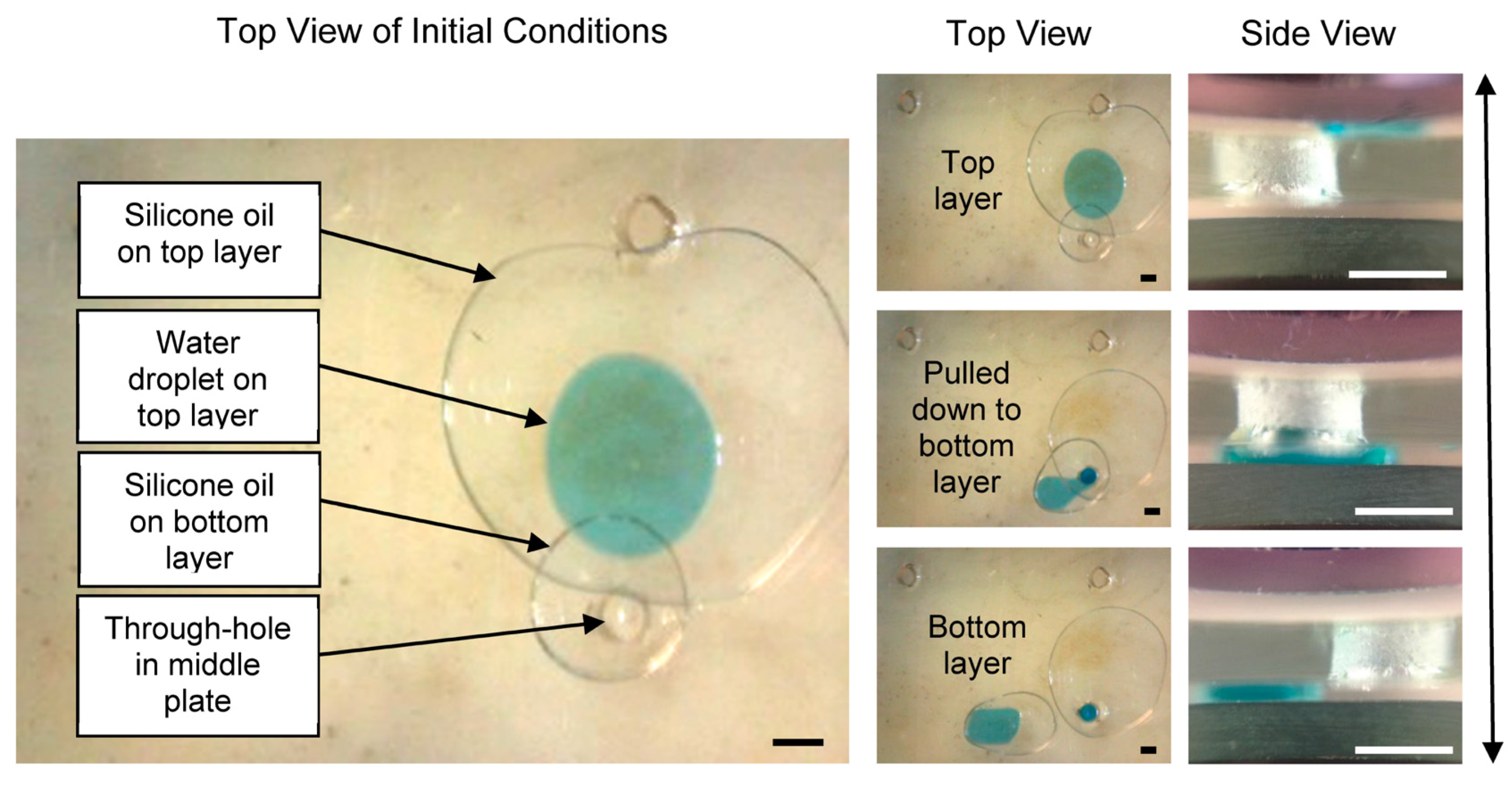
A ~3-µL droplet of deionized (DI) water with 0.05% (w/v) Pluronics™ F-68 (Sigma-Aldrich, St. Louis, MI, USA) and methylene blue dye was dispensed within the top plane. The droplet was surrounded by 10-cst silicone oil (Dow Corning) to enhance mobility and facilitate droplet insertion into the through-hole channel (Figure 3).
Figure 3.
The initial conditions (left) and experimental verification (right) of reversible vertical functionality on a DµF platform using a through-hole to act as the conduit between the vertically stacked layers. Scale bar = 1 mm.
Figure 3.
The initial conditions (left) and experimental verification (right) of reversible vertical functionality on a DµF platform using a through-hole to act as the conduit between the vertically stacked layers. Scale bar = 1 mm.
2.4.2. Calcium Alginate Hydrogel Particle Sieve
A calcium alginate hydrogel was created within a channel by delivering a 1.5-μL droplet of alginic acid solution into the 1.1-mm diameter channel; this was followed by a droplet of 100 mM CaCl2 to gel the solution in situ. For the sieving experiments, a droplet of DI water was mixed with 1- to 2-μm diameter sulfonated polystyrene beads functionalized with carboxyl groups (Bang’s Laboratories, Fishers, IN, USA, Product #PC04N) and dispensed onto the top layer. A 2-μL droplet of the solution was delivered to the gelled channel and pulled through to the bottom layer by actuating the bottom layer electrodes directly underneath the channel.
2.5. Calcium Alginate Hydrogel Fabrication and Characterization
Calcium alginate hydrogels were fabricated by merging a 2-μL droplet of calcium dichloride (100 mM or 1 M, Fisher Scientific, Waltham, MA, USA) with a 2-μL droplet of 1.2 wt % alginic acid (Sigma-Aldrich) in deionized water. The volumes for each constituent were easily manipulated as discrete droplets using our DµF electrode dimensions; other electrode designs will result in different droplet volumes. Using different droplet volumes of equivalent concentrations would not affect the gelation process, but varying the concentrations of either component would impact the pore size and gelation rate. Using different electrode geometries could affect the diffusion distances, and, hence, the time for Ca2+ ions to diffuse through the resultant hydrogel. The gelation process commenced immediately upon contact between the two droplets and was allowed to continue for 15 min. The calcium alginate hydrogels were characterized primarily by scanning electron microcopy (SEM) and atomic force microscopy (AFM). SEM was used to view the pore structure that resulted from mixing solutions of alginic acid and calcium dichloride either horizontally or vertically. After gelation, the samples were removed from the device to prepare them for SEM imaging. The fully hydrated gel samples were first frozen by immersion in liquid nitrogen and cut in half with a razor blade along the axis of diffusion. The thawed samples then underwent a stepwise dehydration in methanol by soaking them first in 100% DI water, followed by 10 min each in 25%, 50%, 75%, 90%, and 100% methanol solutions. The dehydrated samples were then supercritically dried to render a dry, sponge-like gel [51]. This step was necessary because allowing the gel to dry through evaporation caused collapse of the gel structure via capillary forces. The dried samples were sputter-coated for 90 s to deposit approximately 10–15 nm gold-palladium, and viewed using a JOEL JSM-6700F FE-SEM (Tokyo, Japan).
To analyze physical properties of the calcium alginate gels formed on-chip, AFM was performed on hydrated samples immersed in DI water using a Veeco Dimension Icon Scanning Probe Microscope (Bruker, Billerica, MA, USA). The Young’s modulus was determined by probing the hydrated gel and calculating the stiffness based on cantilever deflection [52]. Bruker DNP-D probes were used in an aqueous environment. The spring constant of the probes were first calibrated by measuring the thermal noise and fitting the response of a simple harmonic oscillator in fluid. The sample stiffness was measured by fitting probe deflection curves according to the Sneddon model and eliminating close range sample-probe interactions [52,53].
3. Results and Discussion
3.1. Vertical Functionality
In this section, we describe the process for moving a droplet from one layer of the device to another and the underlying principles. In the proof-of-principle experiment, shown in Figure 3 and Video S1 (Supplementary Materials), droplets were brought into the channel from the top layer through standard DµF electrode actuation. Scoring the channel walls rendered them hydrophilic and helped the water droplet pass through. Immersing the water droplet in silicone oil helped reduce the surface tension of the liquid and effectively reduce the surface roughness of the channel walls, which enhanced droplet mobility. Electric potentials were then applied to the bottom layer electrodes to pull the water droplet away from the hole in the bottom plate. Typically some liquid was left behind at the channel’s hydrophilic walls. If the walls were pre-coated with the silicone oil, the droplet could be separated from the walls more readily without leaving any liquid behind.
The capillary length λc is defined by Equation (1), where γ is the surface tension between the liquid and the surrounding medium, ρ is the fluid density, and g is gravitational acceleration; it is roughly 2 mm for water in air and 250 µm for water in oil.
Below the capillary length scale, surface forces dominate over gravity [8]. When aqueous droplets come into the vicinity of the hydrophilic channel walls and are drawn near them, the radius of curvature will change at the contact line and will result in a pressure differential. To satisfy equilibrium conditions, the droplet will be forced through the hole. The relationship between the contact angle θ and the surface tension γ at the surface-vapor (sv), surface-liquid (sl), and liquid-vapor (lv) interfaces is described by Young’s equation [1,8].
The sequence shown in Figure 3 could be reversed. Droplets in the bottom layer were moved under the hole where they joined with any residual water adhering to the hydrophilic walls of the channel. The middle plate electrodes were actuated to pull water back up through the channel to the top layer. Droplets were then pulled off from the channel onto the top layer, leaving some residual water on the channel walls.
Water droplets could be moved reversibly between the bottom and top layers several times without loss in functionality. Droplets in the bottom and top layers could also be actuated simultaneously. Automating the actuation of droplets on both levels enables lab-on-a-chip procedures with significant versatility and throughput, as the layers can be stacked and access can be provided between each layer. This eliminates the limitation on system size imposed by standard photolithography fabrication methods and, alongside techniques such as cross-referencing [54] and pin-count aware design methodology [55], may help reduce manufacturing costs through pin-count reduction.
3.2. Characterization of Droplet Forces and Design Parameters
In earlier work by Lee et al., a horizontal capillary on a DµF platform was created and characterized [56]. Because vertical functionality is new to the DµF platform, we proceeded to estimate the force required to insert droplets into a channel between the layers, as this will dictate device design parameters such as the channel radius, gap height, and electrode dimensions needed for insertion. Droplets of water have a characteristic capillary length, λ, of around 2 mm, according to Equation (1). The dimensions of typical DµF devices, including the ones used in these experiments, are below the capillary length, so gravitational forces were ignored in the following derivation.
The modeling of droplet insertion was done for four scenarios, which will be referred to as the initial, trapped, suspended, and final phases (Figure 4). After positioning the droplet above or below a channel, the droplet will assume one of these static conditions. In which scenario the droplet comes to rest will depend on factors such as the Laplace pressure differential and the frictional forces present. These static conditions necessary to transition a droplet from one scenario to the next were considered most important for establishing the design parameters. In this first-order analysis, we did not consider the dynamics of droplet insertion.
Figure 4.
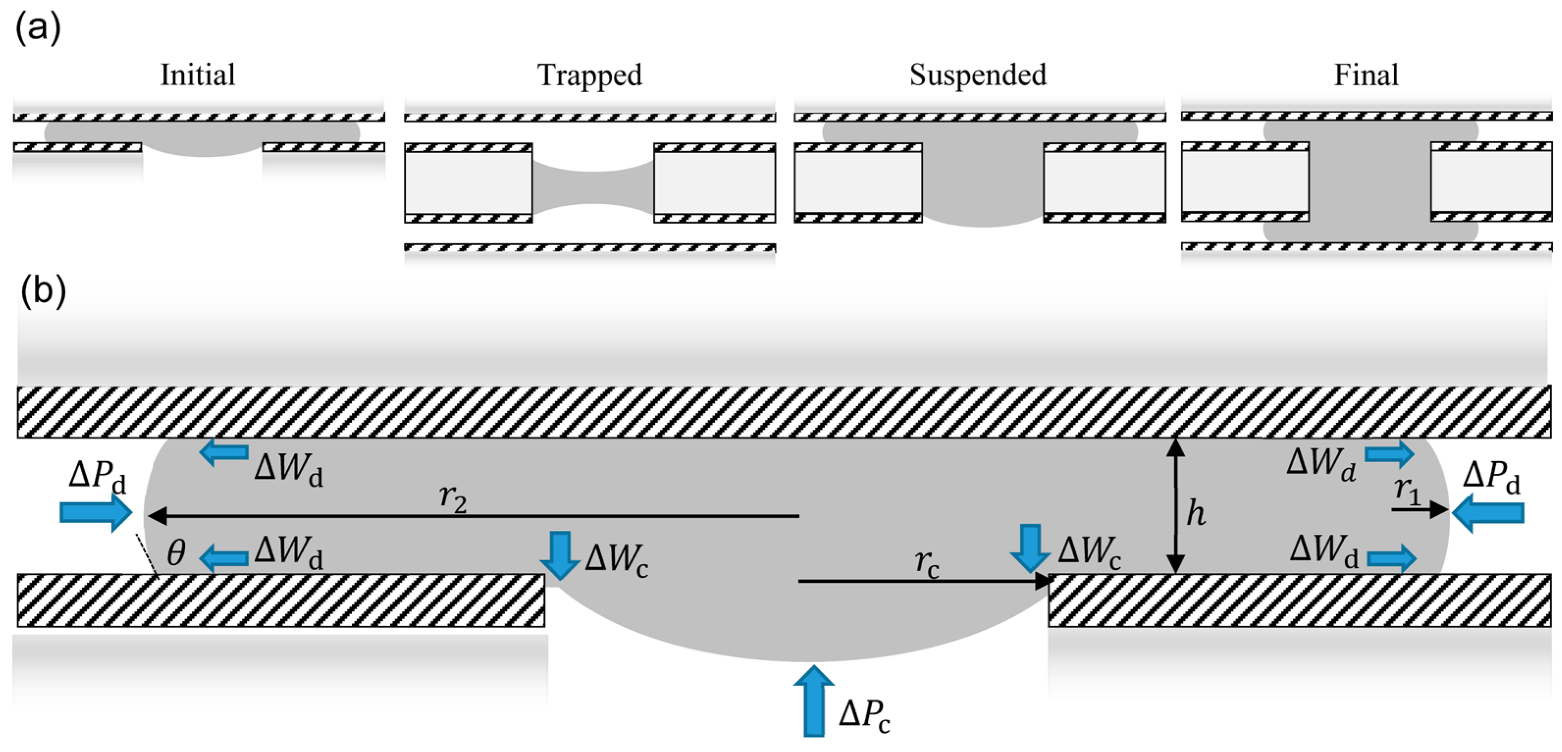
(a) Side schematic of the initial, trapped, suspended, and final scenarios showing the droplet-channel interactions. The hatched areas indicate the hydrophobic top coatings, the light grey areas represent the hydrophilic glass substrate, and the dark grey area represents the water droplet. (b) A free body diagram highlights the equilibrium forces using wide, blue arrows.
Figure 4.
(a) Side schematic of the initial, trapped, suspended, and final scenarios showing the droplet-channel interactions. The hatched areas indicate the hydrophobic top coatings, the light grey areas represent the hydrophilic glass substrate, and the dark grey area represents the water droplet. (b) A free body diagram highlights the equilibrium forces using wide, blue arrows.

During the initial phase, the droplet is assumed to have been positioned over the channel via electrowetting forces. Once the applied voltage is removed, the droplet returns to the non-wetting state and rests above the channel. In this initial state, the droplet is subjected to both a Laplace pressure differential and static friction forces. The Laplace pressure differential, ΔP, is defined by the relationship between the surface tension at the liquid-vapor interface and the two principle radii of curvature r1 and r2 below (Equation (3)).
The Laplace pressure at the surface of the sandwiched droplet is different to that of the droplet at the channel opening because of differences in geometry relating to the radius of curvature. The radius of curvature of the sandwiched droplet is defined by Equations (4) and (5), where r1 and r2 are the principle radii of curvature, h is the gap height between the parallel plates, θ is the contact angle, and V is the droplet volume.
The radius of curvature at the channel opening, rc = r1 = r2, resembles a spherical cap and reduces to the capillary pressure, pc, defined as Equation (6).
When the pressures P at the receding (r) and advancing (a) ends differ, a net driving force acts on the surface, s, which strives to equilibrate the system (Equation (7)).
F = (Pr − Pa)·s
The frictional forces were calculated as the work of adhesion associated with changing the contact angle of water on Teflon-AF® from a sessile drop position to its receding contact angle θ of approximately 105°. Liquid droplets flowing through a capillary tube will experience resistive forces that arise from contact angle hysteresis, contact line friction, and viscous shear forces from the wall and the surrounding medium [57]. The correct mechanisms and modeling for these drag forces in both static and dynamic conditions are not fully understood or agreed upon [8]. The following analysis incorporates only the contact angle hysteresis effect for two reasons. First, the droplet modeling was assumed to be from a static position above the open channel. In this scenario, the droplet has been positioned over the channel via electrode actuation, and as the droplet comes to rest, the velocity, and therefore the dynamic viscosity, becomes zero. Second, empirical data quantifying the viscous drag forces have been found to be from one to several orders of magnitude smaller than both the contact angle hysteresis effect and the driving capillary forces during actuation [57]. Once the capillary forces are large enough to drive the droplet into the channel, and the velocity is greater than zero, the droplet immediately comes in contact with the hydrophilic glass walls and generates a capillary force far greater than the viscous drag forces that arise during the dynamic episode of droplet insertion. The contact angle hysteresis, however, is manifested as resistance to droplet movement from a static position, cosθo, and must be included in the modeling. The resistive force arising from contact angle hysteresis can be thought of as a shear frictional force given by the integral of the change in work of adhesion ΔW at the interface [58].
Equation (8) shows how the work of adhesion, W, is related to the three surface tensions, which are directly related to the energy associated with changing the interfacial contact areas [59].
The change in work of adhesion can be expressed in terms of the receding, cosθoR, and advancing, cosθoA, contact angles for the static friction case [58,59]. Substituting Equation (8) into Equation (2) yields the resistive force per length derived from the work of adhesion (Equation (9)).
The normal force of the Laplace pressure at the droplet edge of the top layer is thus resisted by a work of adhesion that acts at both the top and bottom interfaces of the droplet. By multiplying the equation above by a factor of 2 to account for each plate, and by normalizing the force by the surface area to obtain the normal force acting in the opposite direction of the Laplace pressure, the three primary forces can be combined to form the expression below, which describes the equilibrium condition for droplet insertion Fi (Equation (10)).
The electrode size (width w and length l) and gap height h dictate the minimum droplet volume that can be actuated [60,61]. By solving Equation (10) for rc, one can see how these device dimensions also determine the minimum channel radius that will permit droplet insertion for a given droplet volume (Equation (11)). This equation can be used to predict whether a droplet positioned over a channel will remain in the initial scenario or pass into the channel.
If the Laplace pressure is large enough to overcome the capillary pressure exerted upwards by the hydrophobic layer and the frictional forces that arise from the contact angle hysteresis effect, the droplet will move downwards to reduce the Laplace pressure differential. As the droplet moves downward, it will quickly pass the narrow thickness of the hydrophobic layer and come into contact with the hydrophilic glass walls (the contact angle for soda lime glass θG was measured with a contact angle goniometer to be ~5°). When the droplet touches the hydrophilic walls, the change in surface tension causes a substantial change in contact angle to a near complete wetting condition, and the relatively large capillary force drives the droplet downward through the channel. If the volume of the droplet is less than the volume of the channel, the droplet could become trapped.
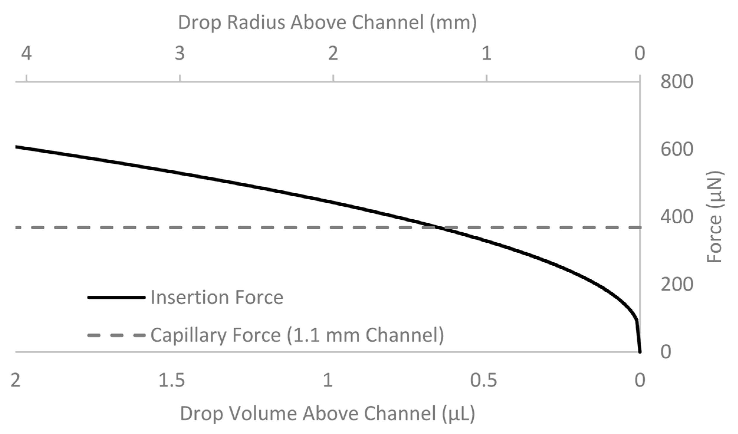
Even if the droplet volume is greater than the channel volume, it could become suspended rather than pulling through to the bottom plate. Rendering the channel walls hydrophilic is of paramount importance for ensuring complete droplet passage. When channels with hydrophobic walls were tested, we found that droplets would not spontaneously pull through. This behavior can be modeled by using Equation (9), considering the forces present at the droplet edges that tend to drive the droplet into the channel along with the forces acting in the channel that oppose this motion. In the absence of hydrophilic channel walls, droplet insertion is dictated by a competition between the droplet geometry above and below the channel. As the pressure differential overcomes the initial pressure required to move the droplet into the channel, the volume and surface area of the droplet above the channel decreases. This leads to a decrease in the driving force, and the droplet quickly comes to rest as the forces equilibrate. Solving Equation (10) shows that for a droplet volume <0.65 µL and a channel diameter of 1.1 mm, the capillary forces exceed the insertion forces (Figure 5). Indeed, our experiments showed that with these volumes and dimensions, vertical functionality could only be obtained with hydrophilic walls. It would theoretically be possible to achieve vertical functionality by adding several droplets to the channel to increase the driving Laplace pressure differential, but this strategy would be inefficient.
Figure 5.
The droplet size (volume and radius) vs. the driving insertion force and the capillary force that resists droplet insertion. The insertion force, derived from the Laplace pressure differential at the droplet edges, is largely dependent on droplet size; the capillary force, derived from the Laplace pressure differential at the channel opening, remains relatively constant. The competing forces demonstrate the difficulty of moving a droplet through a channel with hydrophobic walls. The resistive capillary forces exceed the insertion forces at a droplet volume of 0.65 µL. A larger droplet will move into the channel, but the insertion force will gradually decrease as the volume of the droplet above the channel decreases. The plot was prepared using our experimental conditions: a 1.1-mm diameter channel, a 1-mm thick middle plate, and a 120-µm gap height.

Once the droplet is pulled further down, the droplet comes into contact with the edges of the hydrophobic layer on the bottom side of the middle plate. This results in a capillary force that opposes downward motion. The strong capillary forces that derive from the hydrophilic glass walls also act to restrain the liquid from moving into the bottom layer. To model the suspended and final scenarios and determine the pressures needed to allow the droplet to overcome these capillary forces, we used a similar approach to that used for droplet insertion. The final phase requires modifying Equation (10) to incorporate the strong capillary force imposed by the hydrophilic glass wall pcG into Equation (12).
Once the droplet is injected into the bottom layer by overcoming these forces, the droplet enters the final phase. In the final phase the droplet is in contact with the bottom plate. Applying a voltage to electrodes on the bottom layer in contact with the droplet can then result in the generation of electrowetting forces that pull the droplet into the bottom layer. A challenge is that the strong capillary forces of the hydrophilic channel walls could cause a volume of liquid equivalent to the channel volume to be retained in the channel. The channel surface area and volume must therefore be considered when determining the force that would be required to extract or dispense liquid from the channel once the liquid comes in contact with the bottom layer.
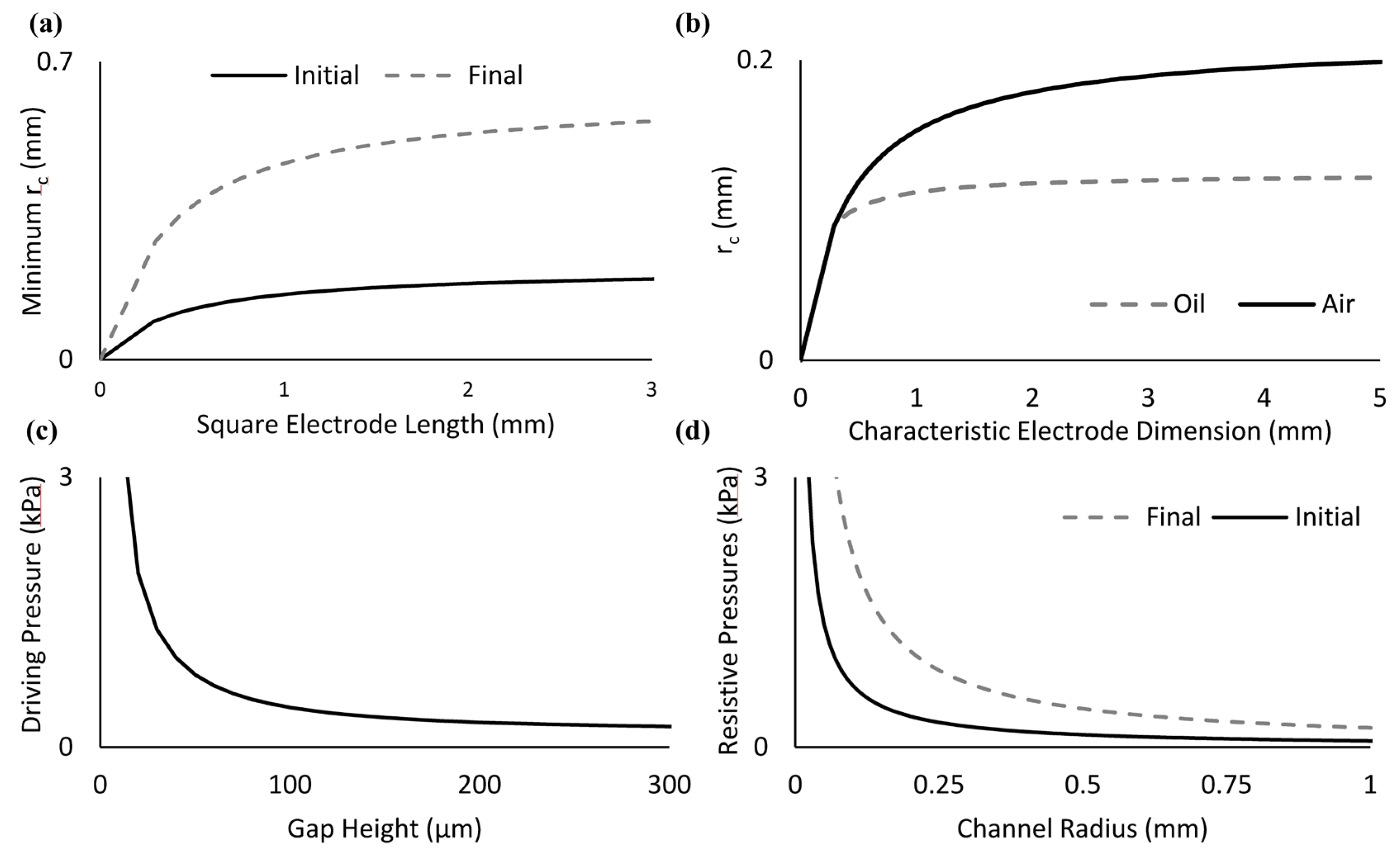
Plotting Equations (10) and (12) yields Figure 6, a series of correlations between critical device geometries and the pressures generated. Figure 6a is useful as a guide for DµF electrode design, relating the electrode size to the minimum channel radius necessary to achieve vertical functionality with a single droplet to enter either the initial phase or the final phase. For a given electrode dimension, Equation (11) dictates the minimum channel radius required to obtain the necessary pressure differential to drive the droplet into the channel. It is important to note that the addition of multiple droplets is a practical method for increasing the pressure differential to a magnitude capable of driving droplet insertion. If droplet insertion does not routinely enter the final phase, a more efficient design may make use of proper dimensioning given by Equation (11). Qualitatively, our experiments using channels with 1.1, 0.74, and 0.45 mm channel diameters behaved as expected. Exceptions to this behavior were observed using the 1.1-mm diameter channel near equilibrium conditions. These deviations were likely due to the drill bit style and manual drilling process; these produced a rough channel wall that could account for variations in the surface quality and hydrophobic film coverage near the channel openings. Adding a second droplet was typically sufficient to result in droplet insertion in these situations.
It is interesting to note that the surface tension does not appear in Equation (11); however, the contact angle is directly related to the Laplace pressure and the work of adhesion through Equations (2) and (9). Immersing the water droplet in oil increases the contact angle [62] and reduces contact angle hysteresis, which makes it possible to insert droplets into channels with a smaller radius and makes vertical functionality easier to achieve (Figure 6b).
The gap height plays a large role in the Laplace pressure via Equation (4): it decreases as the gap height increases. Therefore, the relationship between the gap height and the channel radius plays a significant role in whether vertical functionality can be achieved, and should be a consideration in device design (Figure 6c). Experiments testing larger and smaller gap heights corroborated these findings, with larger gap heights making droplet insertion more difficult and a smaller gap height making droplet insertion easier. In much the same way, the resistive capillary pressure decreases with an increasing channel radius (Figure 6d), and Figure 6c,d highlight that the driving pressure for water becomes greater than the resistive pressure for all gap heights at a channel radius of around 1 mm.
If the driving force for droplet insertion is greater than the minimum initial threshold but less than the final force required for injection into the bottom layer, vertical functionality can only be achieved if the height of the spherical cap protruding through the channel is large enough to allow the liquid to contact the opposing electrode to enable actuation. The height of the spherical cap is related to the channel radius by Equation (13).
Solving for the height of the spherical cap as a function of the volume requires solving a cubic equation and is not trivial. Therefore, the most straightforward tool for checking this design parameter involves first solving for the minimum channel radius via Equation (11). Upon choosing a channel radius greater than this minimum, one can check the height of the maximum spherical cap via Equation (12). If this height is greater than the gap height, one may achieve vertical functionality prior to the final burst-through phase conditions.
Figure 6.
Correlations between the device geometry and characteristics related to vertical droplet functionality derived from Equations (10) and (12). (a) The minimum channel radius required for the droplet to overcome the initial phase and the final phase as a function of square electrode size; (b) the minimum channel radius required for the droplet to overcome the initial scenario when immersed in either oil or air as a function of square electrode size; (c) the driving pressure for a droplet at equilibrium initial conditions as a function of gap height; and (d) the resistive pressure for a droplet at equilibrium conditions in the initial and final phases as a function of channel radius.
3.3. Applications
3.3.1. Sample-in-Sample Delivery with Spatiotemporal Control
Vertical functionality enables droplet delivery through the through-hole channel to a specific region of a sample positioned in the layer below. Diffusion assays are one type of application that could benefit from this functionality. These assays typically require the ability to control the location and timing of reagent delivery [63]: for example, to control cell-cell communication and phenotypic responses in cellular co-culture systems [64,65].
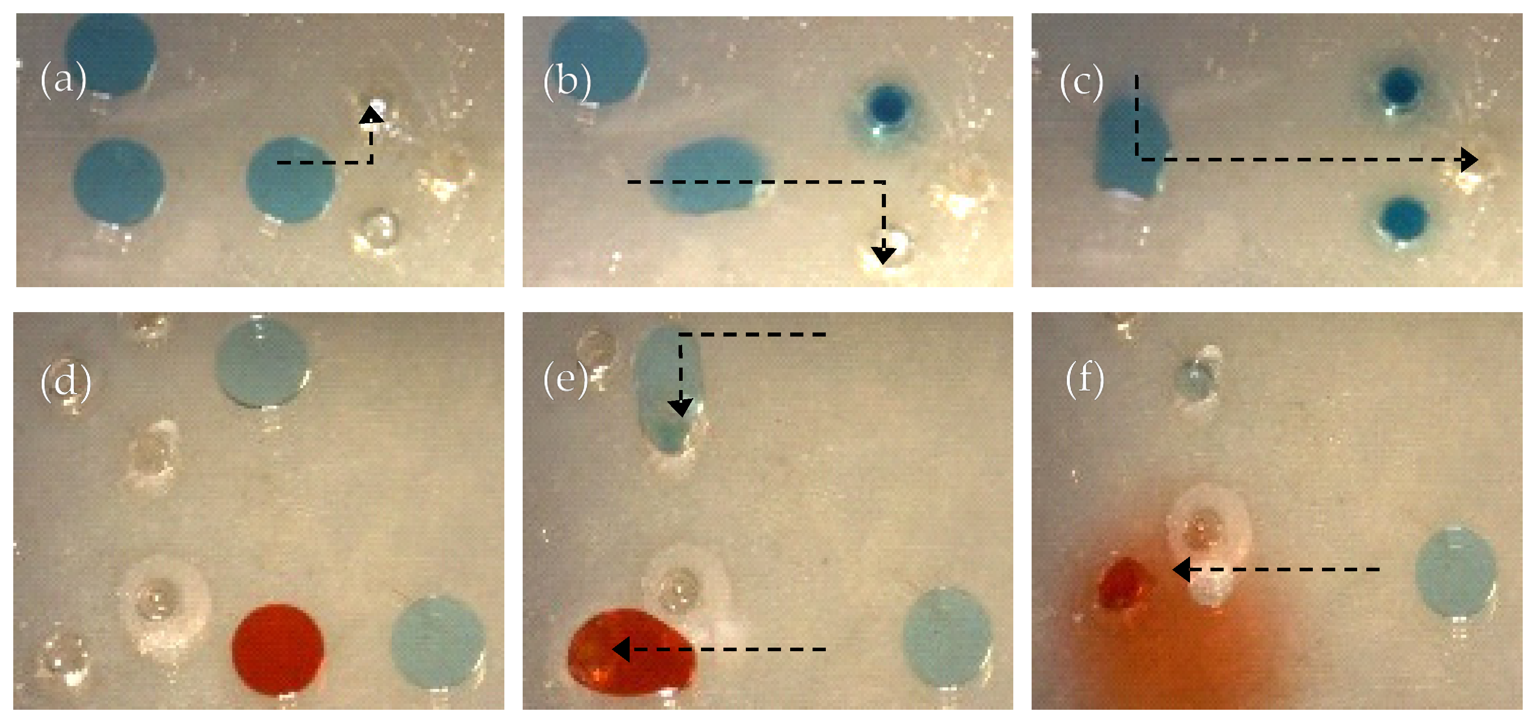
To demonstrate the ability to deliver specific reagents to an internal location within a much larger sample positioned in the bottom layer, DI water droplets containing colored dyes were delivered to a reservoir of DI water from the top to the bottom layer. A large volume of DI water was dispensed on the bottom layer to emulate a homogenous liquid sample analogous to a single cell or co-culture system. Through-holes fabricated within different electrodes were used to insert discrete droplets of dyed water into a continuous water sample in the bottom layer at varying time points (Figure 7). Droplets with blue dye were first positioned on the top layer (Figure 7a). Droplet translation via DµF actuation was performed on each droplet (Figure 7a–c) to deliver them to distinct channels at specific time points. One important observation is that this mode of droplet delivery makes it possible to achieve a radially symmetric diffusion profile within the bottom layer sample. This capability provides a new and straightforward method for producing chemical gradient profiles. An important application would be to create novel hydrogel crosslink gradient profiles for tissue engineering studies.
To demonstrate the ability to automate the simultaneous delivery of two different samples to separate channels, a droplet with blue dye and a droplet with red dye were moved at the same time (Figure 7d,e). A second droplet with blue dye was subsequently delivered to the channel containing the red dye (Figure 7f), where the liquids spontaneously mixed. Taken together, these experiments show that it is possible to use vertical functionality to access the internal regions of a sample, delivering and mixing reagents there with spatiotemporal control not previously achievable on a DµF device.
Figure 7.
Spatial and temporal control of droplet delivery from the top to the bottom layer. (a) Blue droplets positioned on top layer prior to translation and insertion into the bottom layer containing bulk water; (b,c) blue droplets are translated via DµF actuation and inserted into the channels where they mix with the continuous water sample in the bottom layer; (d) blue and red droplets positioned on top layer prior to translation and insertion; (e) automated actuation was used to translate a red and blue droplet simultaneously into separate channels to mix with the continuous water sample in the bottom layer; and (f) a second blue droplet was delivered to same channel as the red droplet.

3.3.2. Calcium Alginate Hydrogel Crosslink Gradient
As noted in the Introduction, gradient hydrogels have diverse applications in cell and tissue culture. Using hydrogels that have radially symmetric crosslink-density profiles is one way to control cellular response times or migration patterns. To make alginate hydrogels, aqueous solutions of calcium dichloride and alginic acid are combined and gelation commences immediately. The crosslink density depends on the relative concentrations of the two species and their rates of diffusion. Using conventional planar DµF devices, samples can only be mixed by merging droplets horizontally (side by side). Combining horizontally adjacent calcium and alginate droplets would result in a crosslink density gradient across the droplet; it would not be possible to create a radially symmetric liquid gradient or hydrogel this way.
We evaluated the feasibility of utilizing vertical functionality to fabricate radially symmetric hydrogel gradients on a DµF device. The idea was to deliver a droplet of CaCl2 solution into a channel containing an alginate solution droplet centered below. The expectation was that once the CaCl2 solution made contact with the alginate solution through the channel, calcium ions would diffuse into the alginate solution, initiate the gelation process, and diffuse outwardly to form a radially symmetric hydrogel. Vertical mixing was achieved by dispensing a 2-μL droplet of 1.2 wt % alginate solution onto the bottom layer, and dispensing a 2-μL droplet of 100 mM CaCl2 solution onto the top layer (Figure 8b, bottom). The droplets contained methylene blue dye to make them easier to image, and both solutions were immersed in silicone oil to enhance mobility. The alginate solution in the bottom layer was first centered underneath the hole by actuating electrodes in the bottom plate. The CaCl2 solution on the top layer was translated to the top of the hole where it was spontaneously pulled in via capillary forces. The solution began mixing immediately upon contact and diffusing into the more viscous alginate sample below. To compare this result with what would be achieved with a conventional 2D DµF device, droplets having the same composition were actuated and merged horizontally within a single layer (Figure 8a, top). At least 15 min was allotted after mixing to allow for gelation to complete prior to further manipulation.
Figure 8.
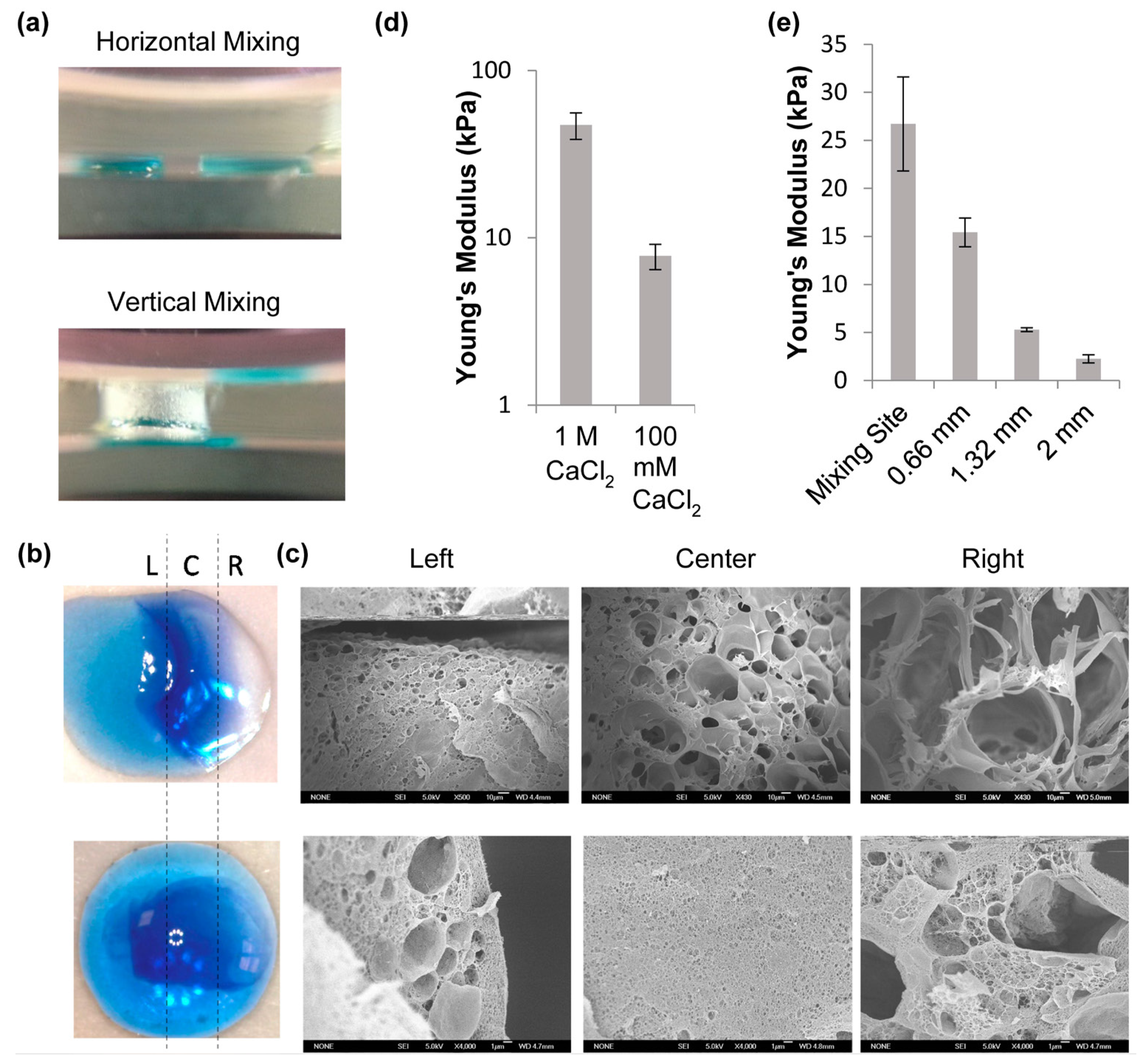
Calcium alginate hydrogel formed by vertical and horizontal mixing. (a) Side view of calcium alginate mixing methods; (b) top-down views of methylene blue-dyed hydrogels formed by horizontal mixing (top) and vertical mixing (bottom); (c) SEM images from three sites across the horizontally mixed gel (top row) and vertically mixed gel (bottom row); (d) Young’s modulus of vertically mixed gels made with two different CaCl2 concentrations; and (e) Young’s modulus vs. distance from the mixing site. The error bars correspond to standard error with n ≥ 10.
Figure 8.
Calcium alginate hydrogel formed by vertical and horizontal mixing. (a) Side view of calcium alginate mixing methods; (b) top-down views of methylene blue-dyed hydrogels formed by horizontal mixing (top) and vertical mixing (bottom); (c) SEM images from three sites across the horizontally mixed gel (top row) and vertically mixed gel (bottom row); (d) Young’s modulus of vertically mixed gels made with two different CaCl2 concentrations; and (e) Young’s modulus vs. distance from the mixing site. The error bars correspond to standard error with n ≥ 10.

To visualize the hydrogel structure, the gels were gently removed from the device to a glass slide. A 1-μL droplet (approximately 10 mg/mL) of methylene blue dye was placed at the center of the hydrogel. After approximately 5 min, the hydrogel was removed from the dye solution and photographed. Figure 8b shows that the hydrogel formed by merging droplets side by side had a horizontal gradient in color intensity, while the hydrogel formed using vertical droplet integration had a more radially symmetric color gradient (Figure 8b).
Scanning electron microscopy (SEM) was used to image the internal hydrogel structure and to validate the qualitative observations of the blue dye imaging assay. The top row of Figure 8c shows an increase in pore size from left to right across the gel sample, consistent with the visual assay (Figure 8b top). The pore size is largest furthest away from the site of mixing because the calcium ion concentration is lowest there (limited diffusion), resulting in fewer crosslinks.
The bottom row of Figure 8c shows the SEM images of the gel formed using vertical mixing. The images show a much lower crosslink density on the left and right compared with the center, the locus of initial mixing. The crosslink density gradient appears qualitatively to be radially symmetric and is consistent with what was observed via the visual assay.
A gradient in crosslink density will result in a stiffness gradient. One way to measure the stiffness of a hydrogel is to use AFM and calculate the Young’s modulus. We used this method to compare the stiffness gradients of hydrogels prepared by horizontal and vertical mixing (Figure 8d). First, gels were made using either 1 M or 100 mM CaCl2; their stiffness was characterized by AFM and the results compared with literature values to validate the method [66,67,68]. After establishing both the accuracy and precision, we used AFM to characterize the stiffness across each gel, determining the Young’s modulus at the mixing site and at one-third, two-thirds, and all the way across the gel for the horizontally mixed samples, and at similar distances for the vertically mixed samples. Figure 8e shows that for both types of gels, the stiffness decreased significantly with increasing distance from the initial site of mixing. The gradients in gel stiffness are qualitatively consistent with the gradient in crosslink density shown in the SEM images.
These experiments demonstrate that radial gradients in hydrogel crosslink density can be generated using vertical functionality on a DµF device. This method for fabricating gradient hydrogels can be applied to on-chip tissue engineering applications and other hydrogel-based assays. For example, cells are encapsulated within hydrogels for cell migration assays that are used to probe phenomena such as wound healing and cancer progression. It should be possible to control both the porosity and stiffness gradients of the hydrogels and determine how cell migration and other behaviors depend on these physical characteristics. In turn, this may facilitate development of improved tissue models, leading to greater understanding of the role of gradients in tissue development and transformation. Hydrogels with radial crosslink density profiles could also prove useful in lab-on-a-chip drug screening assays.
3.3.3. Embryoid Body (EB) Sample Retrieval
In general, the long-term culture of EBs requires the ability to create hanging drops that promote spheroid development, and to exchange media to add growth factors so that the culture can be maintained for extended periods of time. Recently, Aijian and Garrell [38] demonstrated cell spheroid formation and growth in hanging droplets using a DµF platform. A challenge that was identified with the device design was that it was not easy to retrieve and relocate the spheroids, once formed, without dismantling the device. Actuating the electrode near the hanging drop would pull away some of the liquid from the well while leaving the spheroid in place in a small amount of residual liquid. While this is a good feature for medium exchange, it renders the sample immobile.
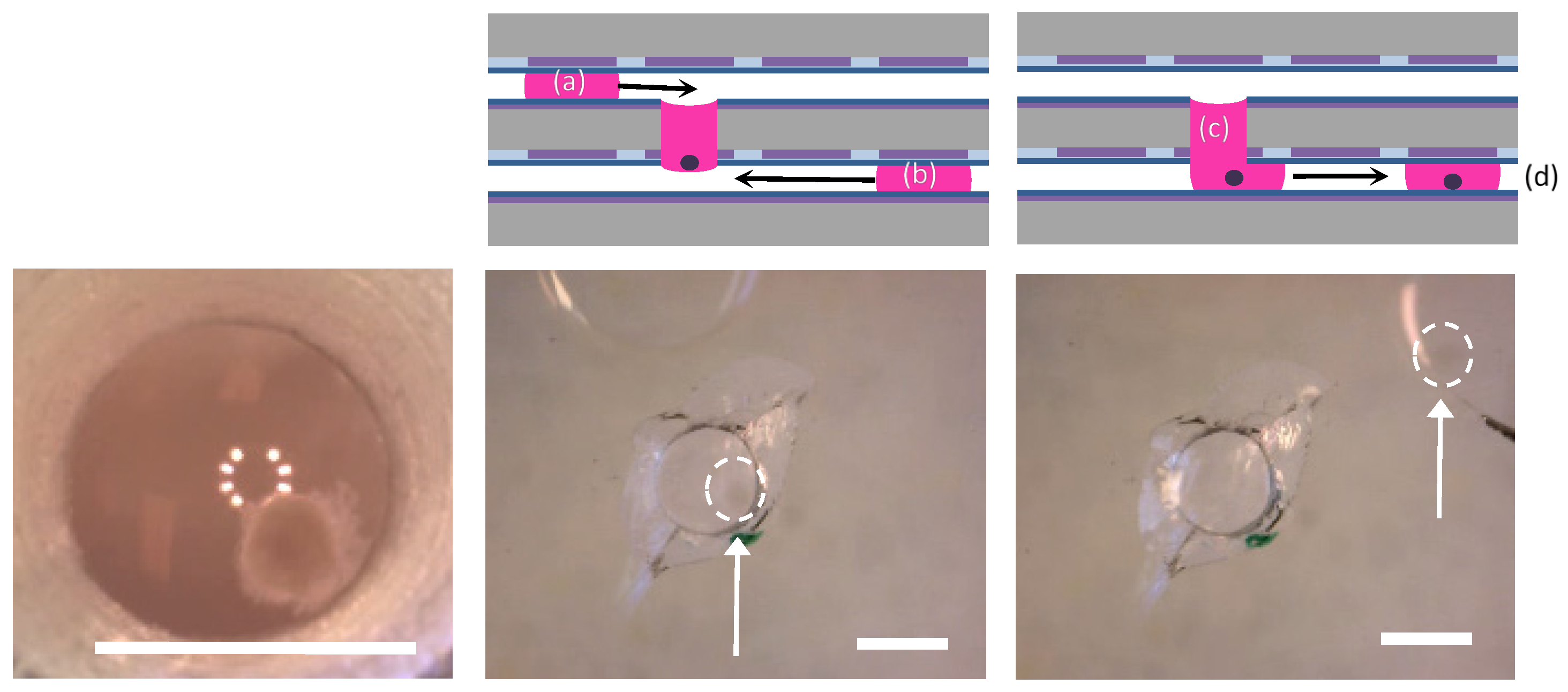
An example where it may desirable to relocate or retrieve a spheroid is the culture of EBs for cardiomyogenesis and certain cardiomyogenic assays. The ability to impart electric fields to actuate and sense cellular characteristics, for example, requires the sample to be positioned near electrodes [69,70,71]. We hypothesized that using a second plane below the hanging drop would provide a path for a delivering a new droplet to the hanging drop that could be used to retrieve the EB. We designed an experiment to retrieve an embryonic stem cell EB, formed as described in [72], from a well by delivering a droplet of media to the hanging drop via the bottom layer. We found that the EB fell into the droplet on the bottom layer when the two droplets came into contact. The droplet on the bottom plane containing the EB was then actuated and moved away from the channel and back in between the parallel plate electrodes, as shown in Figure 9 and Video S2 in the Supplementary Materials. This experiment was repeated several times (>5) to ensure repeatability. One of the tests failed to retrieve the EB; in this instance, a droplet was dispensed on the bottom layer while leaving the EB within the hanging drop. The dispensed droplet was returned to the hanging drop and the EB was successfully retrieved on the second attempt.
This experiment shows that it is possible to use the top plane to deliver a cell suspension, exchange media, and deliver growth factors in order to culture EBs, and to use the bottom plane to retrieve the sample at a later time. Subsequent processing can then be performed, such as exposing the EB to electric fields for directing differentiation or impedance sensing, or delivering the EB to an adhesion pad for monolayer growth and monitoring.
Figure 9.
An EB (far left image) inside of an on-chip well, and the protocol used for media replacement and sample retrieval. A side schematic showing the protocol for EB growth and media replenishment for long-term culture via the top plane (a), and spheroid retrieval (b,c) and sensing (d) via the bottom plane. The images below the schematic highlight an EB inside of the well (dotted circle). A droplet is moved to the well from the bottom plate (center images). After the droplets merge, the EB falls to the bottom layer, and the droplet can be actuated away with the EB sample inside (right images). Scale bar = 1 mm.
3.3.4. Particle Sieving
As a final application, we used vertical functionality to create a hydrogel within a channel that could act as a particle sieve. This application was motivated by bead-based immunoassays. These assays are promising because of their selectivity and specificity, but they require easy and effective ways for sorting, trapping, and filtering microparticles [63]. Recently, Chen et al. showed that hydrogel posts could be fabricated on a device to mechanically filter particles [73]. Droplets were brought into contact with either side of the posts; particles in the droplets could be sieved based on the hydrogel post spacing. The primary limitation to this approach is the micro-post fabrication. The posts must be fabricated before performing any assays, they cannot be altered in situ, and the filtering capabilities are constrained by the difficulty in achieving fine spacing of the posts. Additionally, the fixed post length constrains the droplet size. Larger droplet volumes may allow particles to flow around the posts if the posts do not extend far enough to each side, whereas our design requires the entire droplet to pass through the channel regardless of volume.
For our proof-of-principle experiment, a calcium alginate hydrogel was fabricated within a channel and a polystyrene bead-contained droplet was pulled through it as it passed from the top layer to the bottom layer. The water was able to pass through the gel and form a new discrete droplet on the bottom layer that did not contain any of the polystyrene beads. As shown in Figure 10, the beads were effectively sieved by the gel and remained on the top layer (Video S3 in Supplementary Materials). The experiment was successfully repeated three times using the same device with each run using a new gel sieve. A single proof-of-principle experiment using 10-μm-sized polystyrene beads that were closer to cells in size was performed. Again, a droplet was successfully sieved through the gel solution onto the bottom layer.
This technique for hydrogel-based particle sieving pulls the entire sample through the channel and into the bottom layer. This effectively filters out all particles that are larger than the gel pore size. The hydrogel crosslink density and porosity can be tailored to different sizes based on gelation conditions and component concentrations, providing an easy way to tailor particle-sieving characteristics in situ. Conveniently, calcium alginate can be gelled and de-gelled through the delivery of a monovalent cation solution, such as sodium chloride. This property would enable sieves to be created and eliminated as needed during a multi-step protocol. It also enables recovery of the trapped particles for downstream processing or analysis.
Figure 10.
A droplet of DI water containing 1- to 2-μm diameter polystyrene beads was pulled down from the top layer through a hydrogel sieve to the bottom layer. The side schematic (left) depicts a droplet containing the polystyrene beads on the top layer next to a channel with a calcium alginate hydrogel spanning its length. The droplet is pulled through to the bottom layer, leaving the beads behind, effectively sieved by the calcium alginate hydrogel. The top-down images (right) show the experimental equivalent of these steps. The darker droplet contains the polystyrene beads. Once the droplet is pulled through to the bottom layer, the droplet is clear again after the beads are sieved by the calcium alginate hydrogel in the channel. Scale bar = 1 mm.

4. Conclusions
We have described the incorporation of through-holes on a multi-layer planar DµF device as a means to introduce vertical functionality, specifically the electric field-induced actuation of discrete liquid droplets between the layers in addition to the conventional movement within each layer. Three functional applications were demonstrated. First, sample-in-sample droplet delivery was performed with spatiotemporal control, and was used to produce a calcium alginate hydrogel with a radially symmetric crosslink gradient. Second, a method for producing cell spheroids on-chip was enhanced by demonstrating a means for retrieving the sample for downstream processing. Finally, an on-chip hydrogel sieve was fabricated that enabled complete particle removal.
Since the initial development of DµF, its uses and capabilities have expanded considerably and are quite diverse, despite the limitation of actuating droplets within a single two-dimensional plane. Incorporating vertical functionality can enable many useful and interesting applications of DµF platforms, including studies of surface interactions, membrane dynamics, bioseparations, and drug delivery.
Further enhancements for specific applications are possible. These could include tailoring the channel geometry and surface chemistry, as well as optimizing the channel size, electrode geometry, and actuation voltage for specific processes and for liquids other than water. In particular, improvements to the device design could eliminate the small volume of sample typically left behind at the channel walls. This would improve downstream processing by eliminating potential sample contamination and maintaining a consistent sample volume. Importantly, this approach described here is not limited to two layers; multi-layer stacks and interesting electrode designs could facilitate more complex 3D manipulations. Stacking multiple layers could also significantly increase the potential size of DµF platforms that are generally subject to the constraints of standard photolithography fabrication methods.
Supplementary Materials
The following are available online at https://www.mdpi.com/2072-666X/6/11/1448/s1. Video S1: The video “Vertical Functionality” shows a 2-µL water droplet immersed in silicone oil being translated to a channel. The droplet enters the channel and is pulled through to the bottom layer. The droplet is pulled away from the channel and actuated on the bottom layer. The droplet is then brought back to the channel. A droplet is then actuated and pulled away from the channel onto the top layer. The video speed was increased by 4× to shorten the viewing time. Video S2: The video “EB Retrieval” shows a droplet of cell culture media being delivered to a hanging drop in a channel containing an EB made of human embryonic stem cells via the bottom layer. Once the droplet contacts the channel, the two liquid media solutions combine to form a bridge where the EB falls into the bottom layer. A droplet is then actuated away from the channel to pull off a droplet containing the EB. The video speed was increased by 4× to shorten the viewing time. Video S3: The video “Sieve” shows a droplet containing 1- to 2-µm sulfonated polystyrene beads functionalized with carboxyl groups positioned over a calcium alginate hydrogel formed within a channel. The droplet is actuated on the bottom layer side, pulling the droplet slowly through to the bottom layer. A clear, bead-free droplet is then pulled away from the channel. The dark gray beaded solution remains over the calcium alginate hydrogel. The video speed was increased by 4× to shorten the viewing time.
Acknowledgments
The authors would like to thank Andrew Aijian for help with our digital microfluidic platform operation, the UCLA California NanoSystems Institute (CNSI) for access and assistance with the Integrated Systems and Nanofabrication Cleanroom (ISNC), and UCLA Atsushi Nakano and his lab for access to cellular embryoid bodies.
Author Contributions
B.B. conceptualized and designed the project, executed experiments, analyzed data, developed theoretical framework, and wrote the report. R.G. discussed the concept of the project, reviewed the research, wrote and edited the report.
Conflicts of Interest
The authors declare no conflict of interest.
References
- Mugele, F.; Baret, J.-C. Electrowetting: From basics to applications. J. Phys. Condens. Matter 2005, 17, R705–R775. [Google Scholar] [CrossRef]
- Cho, S.K.; Moon, H.; Chang-Jin, K. Creating, transporting, cutting, and merging liquid droplets by electrowetting-based actuation for digital microfluidic circuits. J. Microelectromech. Syst. 2003, 12, 70–80. [Google Scholar] [CrossRef]
- Choi, K.; Ng, A.H.C.; Fobel, R.; Wheeler, A.R. Digital microfluidics. Annu. Rev. Anal. Chem. 2012, 5, 413–440. [Google Scholar] [CrossRef] [PubMed]
- Jebrail, M.J.; Bartschb, M.S.; Patel, K.D. Digital microfluidics: A versatile tool for applications in chemistry, biology and medicine. Lab Chip 2012, 12, 2452–2463. [Google Scholar] [CrossRef] [PubMed]
- Fobel, R.; Fobel, C.; Wheeler, A.R. Dropbot: An open-source digital microfluidic control system with precise control of electrostatic driving force and instantaneous drop velocity measurement. Appl. Phys. Lett. 2013, 102, 193513. [Google Scholar] [CrossRef]
- Paik, P.; Pamula, V.K.; Fair, R.B. Rapid droplet mixers for digital microfluidic systems. Lab Chip 2003, 3, 253–259. [Google Scholar] [CrossRef] [PubMed]
- Sukhatme, S.; Agarwal, A. Digital microfluidics: Techniques, their applications and advantages. J. Bioeng. Biomed. Sci. 2012, S8, 001. [Google Scholar]
- Nelson, W.C.; Kim, C.-J. Droplet actuation by electrowetting-on-dielectric (EWOD): A review. J. Adhes. Sci. Technol. 2012, 26, 1747–1771. [Google Scholar] [CrossRef]
- Aijian, A.P.; Chatterjee, D.; Garrell, R.L. Fluorinated liquid-enabled protein handling and surfactant-aided crystallization for fully in situ digital microfluidic MALDI-MS analysis. Lab Chip 2012, 12, 2552–2559. [Google Scholar] [CrossRef] [PubMed]
- Chatterjee, D.; Hetayothin, B.; Wheeler, A.R.; King, D.J.; Garrell, R.L. Droplet-based microfluidics with nonaqueous solvents and solutions. Lab Chip 2005, 6, 199–206. [Google Scholar] [CrossRef] [PubMed]
- Chatterjee, D.; Shepherd, H.; Garrell, R.L. Electromechanical model for actuating liquids in a two-plate droplet microfluidic device. Lab Chip 2009, 9, 1219–1229. [Google Scholar] [CrossRef] [PubMed]
- Zeng, J.; Korsmeyer, T. Principles of droplet electrohydrodynamics for lab-on-a-chip. Lab Chip 2004, 4, 265–277. [Google Scholar] [CrossRef] [PubMed]
- Abdelgawad, M.; Watson, M.; Wheeler, A. Hybrid microfluidics: A digital-to-channel interface for in-line sample processing and chemical separations. Lab Chip 2009, 9, 1046–1051. [Google Scholar] [CrossRef] [PubMed]
- Wang, W.; Jones, T.B. Moving droplets between closed and open microfluidic systems. Lab Chip 2015, 15, 2201–2212. [Google Scholar] [CrossRef] [PubMed]
- Ren, H.; Fair, R.B.; Pollack, M.G. Automated on-chip droplet dispensing with volume control by electro-wetting actuation and capacitance metering. Sens. Actuators B Chem. 2004, 98, 319–327. [Google Scholar] [CrossRef]
- Bhargava, K.C.; Thompson, B.; Malmstadt, N. Discrete elements for 3D microfluidics. Proc. Natl. Acad. Sci. USA 2014, 111, 15013–15018. [Google Scholar] [CrossRef] [PubMed]
- Yang, H.; Fan, S.-K.; Lin, C.-P.; Wu, C.-T.; Hsu, W. 3D Droplet Transportations by EWOD Actuations on Flexible Polymer Films. In Proceedings of ASME 2005 International Mechanical Engineering Congress and Exposition, Orlando, FL, USA, 5–11 November 2005; pp. 249–252.
- George, S.M.; Moon, H. Three dimensional tissue based digital microfluidic screening platform. In Proceedings of 2011 15th International Conference on Miniaturized Systems for Chemistry and Life Sciences (MicroTAS 2011), Seattle, WA, USA, 2–6 October 2011; pp. 1545–1547.
- Ay, C.; Yeh, C.-C.; Hsu, M.-C.; Hurng, H.-Y.; Kwok, P.C.L.; Chang, H.-I. Evaluation of the correlation between focal adhesion kinase phosphorylation and cell adhesion force using “DEP” technology. Sensors 2012, 12, 5951–5965. [Google Scholar] [CrossRef] [PubMed]
- Fan, S.-K.; Huang, P.-W.; Wange, T.-T.; Peng, Y.-H. Cross-scale electric manipulations of cells and droplets by frequency-modulated dielectrophoresis and electrowetting. Lab Chip 2008, 8, 1325–1331. [Google Scholar] [CrossRef] [PubMed]
- Huang, Y.; Wang, X.B.; Becker, F.F.; Gascoyne, P.R.C. Introducing dielectrophoresis as a new force field for field-flow fractionation. Biophys. J. 1997, 73, 1118–1129. [Google Scholar] [CrossRef]
- Huang, Y.; Holzel, R.; Pethig, R.; Wang, X.-B. Differences in the ac electrodynamics of viable and non-viable yeast cells determined through combined dielectrophoresis and electrorotation studies. Phys. Med. Biol. 1992, 37, 1499–1517. [Google Scholar] [CrossRef] [PubMed]
- Luk, V.N.; Fiddes, L.K.; Luk, V.M.; Kumacheva, E.; Wheeler, A.R. Digital microfluidic hydrogel microreactors for proteomics. Proteomics 2012, 12, 1310–1318. [Google Scholar] [CrossRef] [PubMed]
- Chiang, M.-Y.; Fan, S.-K. Electric manipulations of hydrogel on a digital microfluidic platform. In Proceedings of 2012 7th IEEE International Conference on Nano/Micro Engineered and Molecular Systems (NEMS), Kyoto, Japan, 5–8 March 2012; pp. 407–410.
- Pethig, R. Review article—Dielectrophoresis: Status of the theory, technology, and applications. Biomicrofluidics 2010, 4, 4–35. [Google Scholar]
- Gupta, S.; Alargova, R.G.; Kilpatrick, P.K.; Velev, O.D. On-chip dielectrophoretic coassembly of live cells and particles into responsive biomaterials. Langmuir 2009, 26, 3441–3452. [Google Scholar] [CrossRef] [PubMed]
- Vlahovska, P.M.; Gracia, R.S.; Aranda-Espinoza, S.; Dimova, R. Electrohydrodynamic model of vesicle deformation in alternating electric fields. Biophys. J. 2009, 96, 4789–4803. [Google Scholar] [CrossRef] [PubMed]
- MacQueen, L.A.; Buschmann, M.D.; Wertheimer, M.R. Mechanical properties of mammalian cells in suspension measured by electro-deformation. J. Micromech. Microeng. 2010, 20, 1–11. [Google Scholar] [CrossRef]
- Engelhardt, H.; Sackmann, E. On the measurement of shear elastic moduli and viscosities of erythrocyte plasma membranes by transient deformation in high frequency electric fields. Biophys. J. 1988, 54, 495–508. [Google Scholar] [CrossRef]
- Li, H.; Ye, T.; Lam, K.Y. Qualitative and quantitative analysis of dynamic deformation of a cell in nonuniform alternating electric field. J. Appl. Phys. 2011, 110, 1–6. [Google Scholar] [CrossRef]
- Cho, S.K.; Moon, H. Electrowetting on dielectric (EWOD): New tool for bio/micro fluids handling. Biochip. J. 2008, 2, 79–96. [Google Scholar]
- Fair, R.B.; Khlystov, A.; Tailor, T.D.; Ivanov, V.; Evans, R.D.; Griffin, P.B.; Vijay, S.; Pamula, V.K.; Pollack, M.G.; Zhou, J. Chemical and biological applications of digital-microfluidic devices. IEEE Des. Test Comput. 2007, 24, 10–24. [Google Scholar] [CrossRef]
- Fiddes, L.K.; Luk, V.N.; Au, S.H.; Ng, A.H.C.; Luk, V.; Kumacheva, E.; Wheeler, A.R. Hydrogel discs for digital microfluidics. Biomicrofluidics 2012, 6, 014112. [Google Scholar] [CrossRef] [PubMed]
- Zhang, J.; Yan, S.; Alici, G.; Nguyen, N.-T.; Di Carlo, D.; Li, W. Real-time control of inertial focusing in microfluidics using dielectrophoresis (dep). RSC Adv. 2014, 4, 62076–62085. [Google Scholar] [CrossRef]
- Emaminejad, S.; Dutton, R.W.; Davis, R.W.; Javanmard, M. Multiplexed actuation using ultra dielectrophoresis for proteomics applications: A comprehensive electrical and electrothermal design methodology. Lab Chip 2014, 14, 2105–2114. [Google Scholar] [CrossRef] [PubMed]
- Su, H.-W.; Prieto, J.L.; Voldman, J. Rapid dielectrophoretic characterization of single cells using the dielectrophoretic spring. Lab Chip 2013, 13, 4109–4117. [Google Scholar] [CrossRef] [PubMed]
- Barbulovic-Nad, I.; Auab, S.H.; Wheeler, A.R. A microfluidic platform for complete mammalian cell culture. Lab Chip 2010, 10, 1536–1542. [Google Scholar] [CrossRef] [PubMed]
- Aijian, A.P.; Garrell, R.L. Digital microfluidics for hanging drop cell spheroid culture. J. Lab. Autom. 2014, 20, 283–295. [Google Scholar] [CrossRef] [PubMed]
- Au, S.H.; Fobel, R.; Desai, S.P.; Voldman, J.; Wheeler, A.R. Cellular bias on the microscale: Probing the effects of digital microfluidic actuation on mammalian cell health, fitness and phenotype. Integr. Biol. 2013, 5, 1014–1025. [Google Scholar] [CrossRef] [PubMed]
- Geckil, H.; Xu, F.; Zhang, X.; Moon, S.; Demirci, U. Engineering hydrogels as extracellular matrix mimics. Nanomedicine 2010, 5, 469–484. [Google Scholar] [CrossRef] [PubMed]
- Sant, S.; Hancock, M.J.; Donnelly, J.P.; Iyer, D.; Khademhosseini, A. Biomimetic gradient hydrogels for tissue engineering. Can. J. Chem. Eng. 2010, 88, 899–911. [Google Scholar] [CrossRef] [PubMed]
- Lee, K.; Silva, E.A.; Mooney, D.J. Growth factor delivery-based tissue engineering: General approaches and a review or recent developments. J. R. Soc. Interface 2011, 8, 153–170. [Google Scholar] [CrossRef] [PubMed]
- Johnson, P.C.; Mikos, A.G.; Fisher, J.P.; Jansen, J.A. Strategic directions in tissue engineering. Tissue Eng. 2007, 13, 2827–2837. [Google Scholar] [CrossRef] [PubMed]
- Wang, J.H.-C.; Thampatty, B.P. Mechanobiology of adult and stem cells. Int. Rev. Cell Mol. Biol. 2008, 271, 301–334. [Google Scholar] [PubMed]
- Sheehy, S.P.; Grosberg, A.; Parker, K.K. The contribution of cellular mechanotransduction to cardiomyocyte form and function. Biomech. Model. Mechanobiol. 2012, 11, 1227–1239. [Google Scholar] [CrossRef] [PubMed]
- George, S.M.; Moon, H. Digital microfluidic three-dimensional cell culture and chemical screening platform using alginate hydrogels. Biomicrofluidics 2015, 9, 024116. [Google Scholar] [CrossRef] [PubMed]
- Rowley, J.A.; Mooney, D.J. Alginate type and rgd density control myoblast phenotype. J. Biomed. Mat. Res. 2002, 60, 217–223. [Google Scholar] [CrossRef] [PubMed]
- Wan, L.Q.; Jiang, J.; Arnold, D.E.; Guo, X.E.; Lu, H.H.; Mow, V.C. Calcium concentration effects on the mechanical and biochemical properties of chondrocyte-alginate constructs. Cell. Mol. Bioeng. 2008, 1, 93–102. [Google Scholar] [CrossRef] [PubMed]
- Cao, L.; Arany, P.R.; Wang, Y.-S.; Mooney, D.J. Promoting angiogenesis via manipulation of VEGF responsiveness with notch signaling. Biomaterials 2009, 30, 4085–4093. [Google Scholar] [CrossRef] [PubMed]
- Primiceri, E.; Chiriaco, M.S.; Rinaldi, R.; Maruccio, G. Cell chips as new tools for cell biology—Results, perspectives and opportunities. Lab Chip 2013, 13, 3789–3802. [Google Scholar] [CrossRef] [PubMed]
- Yin, C.; Ying, L.; Zhang, P.-C.; Zhuo, R.-X.; Kang, E.-T.; Leong, K.W.; Mao, H.-Q. High density of immobilized galactose ligand enhances hepatocyte attachment and function. J. Biomed. Mater. Res. 2003, 67, 1093–1104. [Google Scholar] [CrossRef] [PubMed]
- Zhu, Y.; Dong, Z.; Wejinya, U.C.; Jin, S.; Ye, K. Determination of mechanical properties of soft tissue scaffolds by atomic force microscopy nanoindentation. J. Biomech. 2011, 44, 2356–2361. [Google Scholar] [CrossRef] [PubMed]
- Heuberger, M.; Dietler, G.; Schlapbach, L. Elastic deformations of tip and sample during atomic force microscope measurements. J. Vac. Sci. Technol. B 1996, 14, 1250–1254. [Google Scholar] [CrossRef]
- Yeung, J.H.C.; Young, E.F.Y.; Choy, C.S. In Reducing pin count on cross-referencing digital microfluidic biochip. In Proceedings of 2014 IEEE International Symposium on Circuits and Systems (ISCAS), Melbourne, Australia, 1–5 June 2014; pp. 790–793.
- Yang, Z.; Chakrabarty, K. Pin-count-aware online testing of digital microfluidic biochips. In Proceedings of 2010 28th VLSI Test Symposium (VTS), Santa Cruz, CA, USA, 19–22 April 2010; pp. 111–116.
- Lee, J.; Moon, H.; Fowler, J.; Schoelhammer, T.; Kim, C.-J. Electrowetting and electrowetting-on-dielectric for microscale liquid handling. Sens. Actuators A Phys. 2002, 95, 259–268. [Google Scholar] [CrossRef]
- Schertzer, M.J.; Gubarenko, S.I.; Ben-Mrad, R.; Sullivan, P.E. An empirically validated analytical model of droplet dynamics in electrowetting on dielectric devices. Langmuir 2010, 26, 19230–19238. [Google Scholar] [CrossRef] [PubMed]
- Tenan, M.A.; Hackwood, S.; Beni, G. Friction in capillary systems. J. Appl. Phys. 1982, 53, 6687–6692. [Google Scholar] [CrossRef]
- Adamson, A.W.; Gast, A.P. Physical Chemistry of Surfaces, 6th ed.; John Wiley & Sons: Hoboken, NJ, USA, 1997. [Google Scholar]
- Gong, J.; Kim, C.J. All-electronic droplet generation on-chip with real-time feedback control for EWOD digital microfluidics. Lab Chip 2008, 8, 898–906. [Google Scholar] [CrossRef] [PubMed]
- Nelson, W.C.; Kim, C.-J. Monolithic fabrication of EWOD chips for picoliter droplets. J. Microelectromech. Syst. 2011, 20, 1419–1427. [Google Scholar] [CrossRef]
- Brassard, D.; Malic, L.; Normandin, F.; Tabrizianc, M.; Veres, T. Water-oil core-shell droplets for electrowetting-based digital microfluidic devices. Lab Chip 2008, 8, 1342–1349. [Google Scholar] [CrossRef] [PubMed] [Green Version]
- Woolley, C.F.; Hayes, M.A. Recent developments in emerging microimmunoassays. Bioanalysis 2013, 5, 245–264. [Google Scholar] [CrossRef] [PubMed]
- Song, K.; Wang, H.; Wang, H.; Wang, L.; Qiao, M.; Wu, S.; Liu, T. Investigation of the effective action distance between hematopoietic stem/progenitor cells and human adipose-derived stem cells during their in vitro co-culture. Appl. Biochem. Biotechnol. 2011, 165, 776–784. [Google Scholar] [CrossRef] [PubMed]
- Frank, T.; Tay, S. Automated co-culture system for spatiotemporal analysis of cell-to-cell communication. Lab Chip 2015, 15, 2192–2200. [Google Scholar] [CrossRef] [PubMed]
- Banerjee, A.; Arha, M.; Choudhary, S.; Ashton, R.S.; Bhatia, S.R.; Schaffer, D.V.; Kane, R.S. The influence of hydrogel modulus on the proliferation and differentiation of encapsulated neural stem cells. Biomaterials 2009, 30, 4695–4699. [Google Scholar] [CrossRef] [PubMed]
- Candiello, J.; Singh, S.S.; Task, K.; Kumta, P.N.; Banerjee, I. Early differentiation patterning of mouse embryonic stem cells in response to variations in alginate substrate stiffness. J. Biol. Eng. 2013, 7, 9. [Google Scholar] [CrossRef] [PubMed]
- Kong, H.J.; Wong, E.; Mooney, D.J. Independent control of rigidity and toughness of polymeric hydrogels. Macromolecules 2003, 36, 4582–4588. [Google Scholar] [CrossRef]
- Dean, D.A.; Ramanathan, T.; Machado, D.; Sundararajan, R. Electrical impedance spectroscopy study of biological tissues. J. Electrost. 2009, 66, 165–177. [Google Scholar] [CrossRef] [PubMed]
- Peters, M.F.; Scott, C.W.; Ochalski, R.; Dragon, Y.P. Evalulation of cellular impedance measures of cardiomyocyte cultures for drug screening applications. Assay Drug Dev. Technol. 2012, 10, 525–532. [Google Scholar] [CrossRef] [PubMed]
- Shih, S.C.C.; Barbulovic-Nad, I.; Yang, X.; Fobel, R.; Wheeler, A.R. Digital microfluidics with impedance sensing for integrated cell culture and analysis. Biosens. Bioelectron. 2013, 42, 314–320. [Google Scholar] [CrossRef] [PubMed]
- Arshi, A.; Nakashima, Y.; Nakano, H.; Eaimkhong, S.; Evseenko, D.; Reed, J.; Stieg, A.Z.; Gimzewski, J.K.; Nakano, A. Rigid microenvironments promote cardiac differentiation of mouse and human embryonic stem cells. Sci. Technol. Adv. Mater 2013, 14, 025003. [Google Scholar] [CrossRef] [PubMed]
- Chen, S.; Javed, M.R.; Kim, H.-K.; Lei, J.; Lazari, M.; Shah, G.J.; Dooraghi, A.A.; Chatziioannou, A.F.; Dam, R.M.; Keng, P.-Y.; et al. Electrowetting-driven chemical synthesis and radioisotope purification of positron emission tomography (pet) radiotracers. In Proceedings of the 9th International Meeting on Electrowetting and Related Micro/Electrofluidic Science and Technology, Cincinnati, OH, USA, 23–25 June 2014.
© 2015 by the authors; licensee MDPI, Basel, Switzerland. This article is an open access article distributed under the terms and conditions of the Creative Commons by Attribution (CC-BY) license (http://creativecommons.org/licenses/by/4.0/).
Share and Cite
MDPI and ACS Style
Bender, B.F.; Garrell, R.L. Digital Microfluidic System with Vertical Functionality. Micromachines 2015, 6, 1655-1674. https://doi.org/10.3390/mi6111448
AMA Style
Bender BF, Garrell RL. Digital Microfluidic System with Vertical Functionality. Micromachines. 2015; 6(11):1655-1674. https://doi.org/10.3390/mi6111448
Chicago/Turabian StyleBender, Brian F., and Robin L. Garrell. 2015. "Digital Microfluidic System with Vertical Functionality" Micromachines 6, no. 11: 1655-1674. https://doi.org/10.3390/mi6111448