1. Introduction
The monitoring and management of performance and system health of hypersonic aerial vehicles, jet engines, rockets, and so on, relies on the capability to detect a variety of parameters including pressure [
1]. Usually, these applications are accompanied with high-temperature environments, which issue a great challenge to current commercial pressure sensors. For example, the pressure in a turbine engine needs to be measured from 300 °C to 1000 °C at different locations [
2,
3].
Harsh environments such as gas turbine engines, power plants, and material-processing systems generally have temperatures greater than 500 °C [
4]. The typical temperature in these environments is beyond the working temperature of traditional silicon-based devices. For example, the working-temperature range of pressure sensors fabricated in silicon would be less than 200 °C because the electrical and mechanical properties of silicon deteriorate at higher temperature. Owing to temperature characteristics of the P-N junctions, the highest operational temperature of silicon-based electronics is limited to approximately 130 °C. When temperature exceeds 500 °C, the mechanical properties of silicon begin to degrade [
5]. In addition, the electrical wires connecting the device to the electrical signal processing unit will overheats the processing unit causing the measurement system to fail quickly.
Researchers have developed various methods such as active cooling and thermal insulation packaging to extend the operation temperature of current pressure sensors [
6]. However, experiments have shown that most traditional sensors can only be operated at approximately 300 °C, despite the well-designed package, owing to the limited temperature resistance of the kernel sensing unit. Additionally, those package strategies will cause the volume expansion of components, which will lead to poor installation adaptability. In addition to the packaging method, guide pipes have been used for pressure measurement in an engine running test, which usually cause signal distortion compared to the results obtained from
in situ measurement. Therefore, further studies have focused on fabricating sensors by high-temperature-resistant materials such as ceramics [
7,
8,
9], silicon on insulator (SOI) [
10], and SiC [
11,
12,
13]. Among these sensors, wireless passive pressure sensors realized by low-temperature cofired ceramic (LTCC) and high-temperature cofired ceramic (HTCC) technology have demonstrated great prospects owing to the combination of passive a telemetry readout method and temperature-resistant material properties.
In this paper, a wireless passive zirconia-based pressure sensor fabrication by the post-fire metallization is proposed. The sensor is fabricated by two main steps: sintering of the multilayered zirconia tapes and post-fire metallization of Ag pastes separately, which enhances the quality of the sensor compared to that of a sensor fabricated previously by cofiring with platinum pastes. Detailed fabrication processes are presented and the sensor is calibrated using an established calibration system from which an average sensitivity up to 790 kHz/bar is obtained. Further, the high-temperature characteristics of the sensor are investigated from room temperature to 600 °C. At 600 °C, the induced impedance phase dip of the reader antenna related to the proposed sensor is 50° which is quite considerable compared with 6° induced by the cofired sensor.
2. Sensor Design
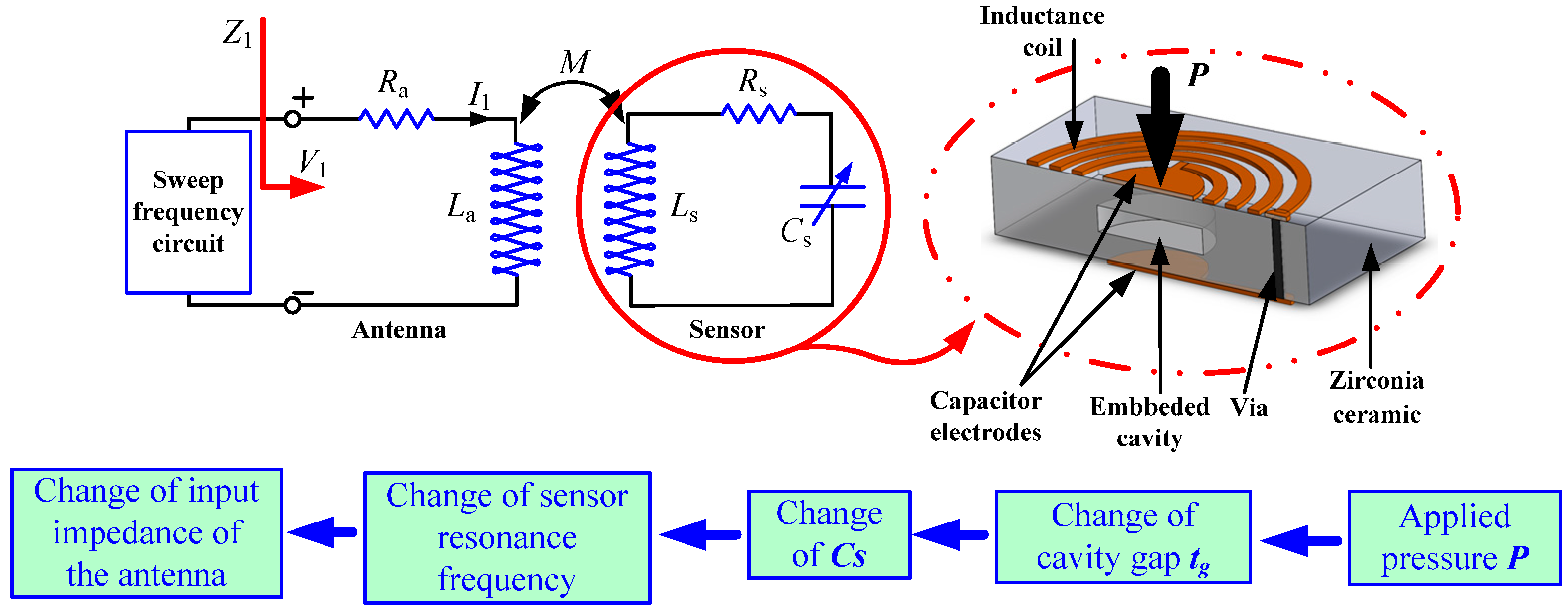
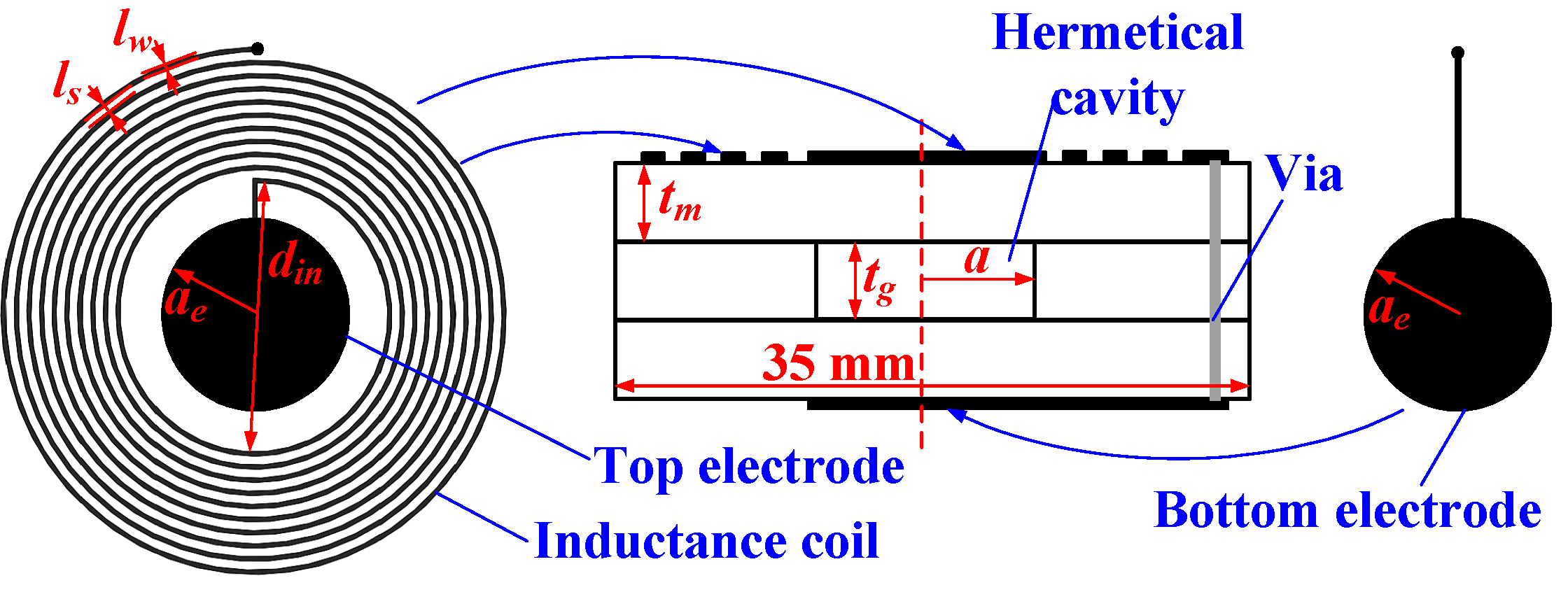
A schematic of the sensor system is presented in
Figure 1, from which it is clear that an LC resonance circuit formed by an invariable inductance coil and a variable capacitor is powered by a reader antenna. From the flow chart in
Figure 1, the capacitance
Cs increases owing to the reduction in the gap between the two capacitor electrodes if pressure is applied to the device,
i.e., the gap size of the cavity between the two membranes decreases. Therefore, the resonant frequency
f0 decreases, which can be coupled with the antenna port through the magnetic link
M between the coils. In addition, the resonance information of the sensor can be extracted and tracked by measuring impedance parameters (phase, real part, magnitude,
etc.) of the antenna.
A cross-sectional model of the sensor consisting of three ceramic tapes is shown in
Figure 2. Before high-temperature sintering, the dimensions of the green tape are 42 mm × 42 mm, and the dimensions are approximately 35 mm × 35 mm after high-temperature sintering owing to shrinkage. The properties of the implemented zirconia ceramic are listed in
Table 1. A sealed cavity is located in the middle of Layer 2, and a capacitor is electrically connected to the inductor, which is designed as a circular planar spiral coil (PSC) and placed on the top surface of Layer 3. The capacitor is a parallel-plate capacitor with circular electrodes in Layer 1 and Layer 3. The relevant geometrical parameters of the capacitor and inductor are listed in
Table 2. The electrical connection between the bottom capacitor plates and the inductance coil is realized by a metalized via. Thus, a passive LC resonator is formed by these components. Furthermore, this type of electrical connection can also be achieved by coating the side wall of the sensor with Ag paste, thereby making the via hole unnecessary. However, a via is implemented in the proposed sensor instead of coating the side wall with Ag paste to achieve a more stable connection and to reduce the complexity of manual manipulation.
Figure 1.
Measurement principle and structure diagram of the pressure sensor.
Figure 1.
Measurement principle and structure diagram of the pressure sensor.
Figure 2.
Cross-sectional model and layout of the sensor.
Figure 2.
Cross-sectional model and layout of the sensor.
Table 1.
Characteristics of the zirconia ceramic.
Table 1.
Characteristics of the zirconia ceramic.
| Quantity | Value |
|---|
| Young’s modulus | 210 GPa |
| Poisson’s Ratio | 0.24 |
| Unfired thickness | 125 μm |
| X,Y Shrinkage | 17.3% ± 1% |
| Z Shrinkage | 18.3% ± 1% |
Table 2.
Geometrical parameters in inductor and capacitor design.
Table 2.
Geometrical parameters in inductor and capacitor design.
| Component | Symbol | Quantity | Value |
|---|
| Inductor | din | inner diameter of the inductance coils | 14 mm |
| lw | width of the coils | 200 μm |
| ls | spacing of the coils | 400 μm |
| n | number of the coils | 10 |
| Capacitor | a | radius of the cavity | 3.6 mm |
| ae | radius of the electrode | 3.8 mm |
| tg | cavity thickness | 125 μm |
| tm | green-tape thickness | 125 μm |
3. Sensor Fabrication
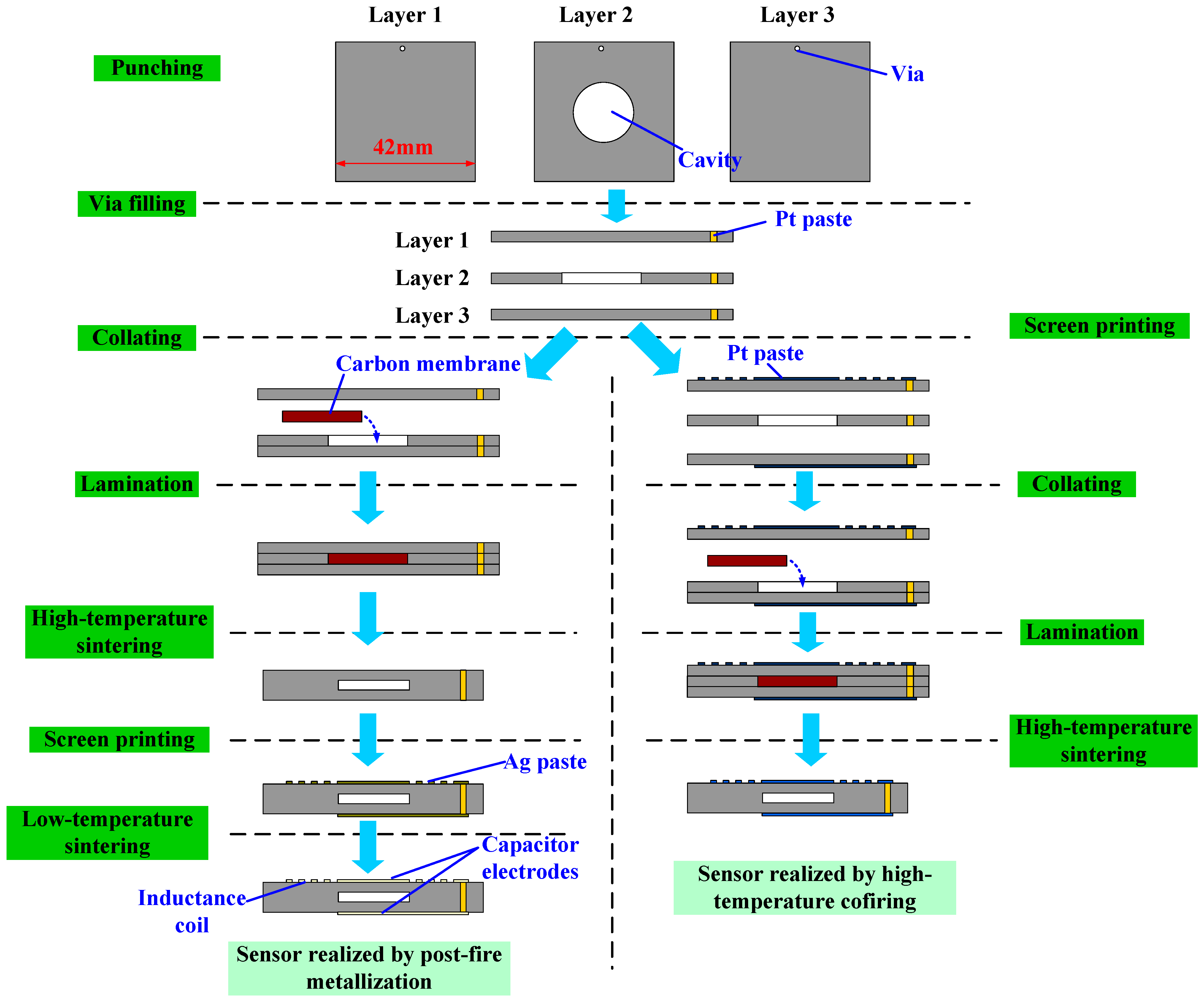
The sensor was fabricated by separately sintering the ceramic substrate and metallic pattern. The fabrication process, as illustrated in
Figure 3, can be roughly divided into punching, via filling, collating, lamination, high-temperature sintering, screen-printing, and-low temperature sintering. In order to provide clearer information about the fabrication process of the sensor, a comparison between the post-fire metallization method and the traditional method using the co-firing technique is also depicted in
Figure 3.
Before punching, the ceramic tape was placed into a dry furnace preheated at 80 °C for 30 min. Then, a numerically controlled punching machine was used to drill a cavity hole in Layer 2 and via holes in all three layers. Next, via holes were filled in by the Pt paste to realize an electrical connection throughout the multilayered tapes. After via filling, Layers 1 and 2 were precisely stacked by the collating machine. Then, the stacked two-layer substrate was removed from the stacking machine, and a carbon membrane which has the same dimensions as the cavity and can volatilize within 600 °C, was placed into the cavity to support the pressure-sensitive membranes to avoid collapsing and cracking during the lamination process. It should be noted that the area of carbon membrane should not be much less than the area of the cavity because it will also lead to cracking in the edge of the cavity. Afterwards, Layer 3 was collated on top of Layer 2.
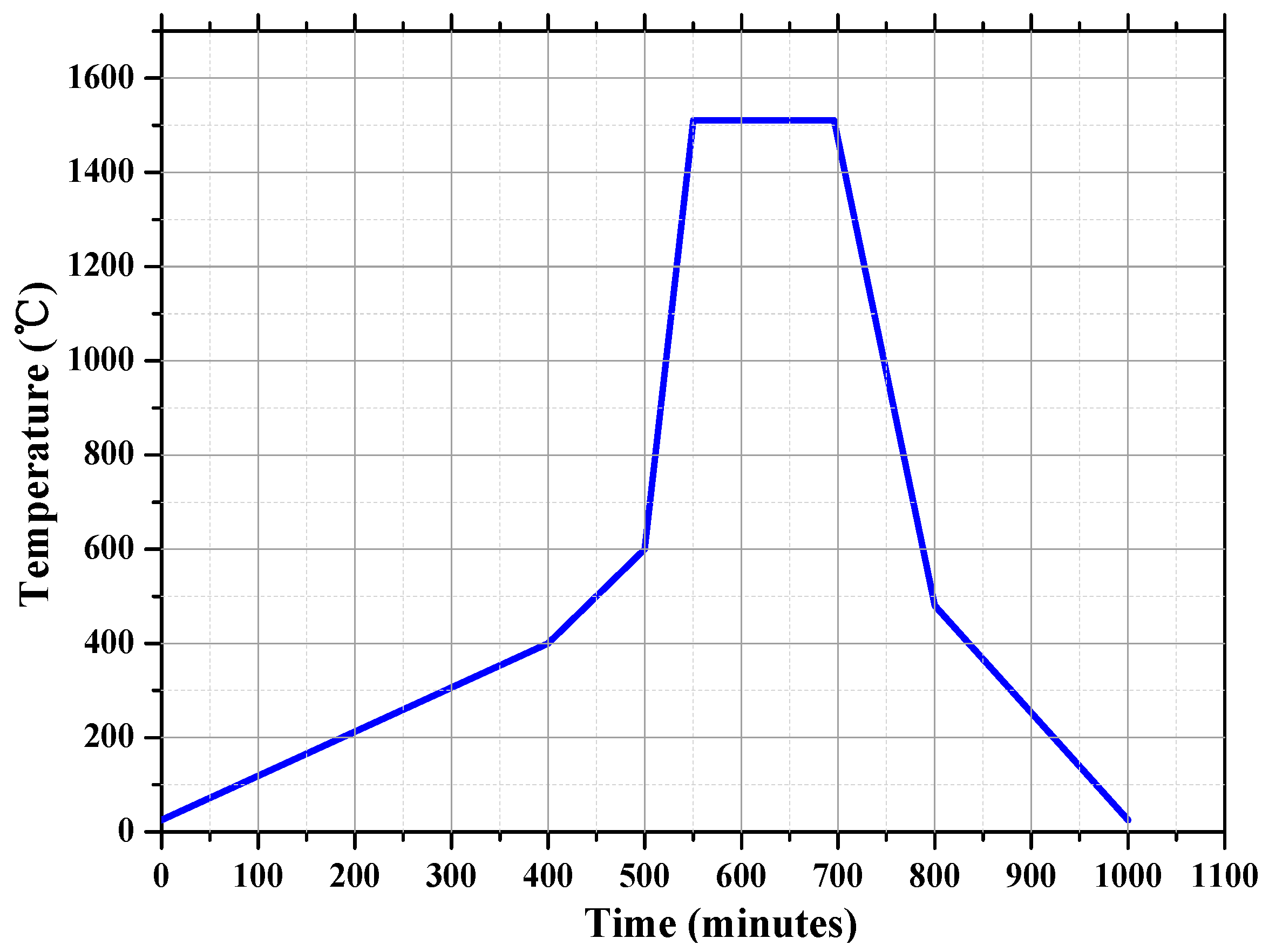
After stacking, lamination was performed, which is quite crucial for the quality of the buried cavity. The first step in the process of lamination is vacuum packaging of the ceramic tape, which ensured that the tapes were isolated from the water during the lamination. Then, the packaged ceramic tape was placed into the lamination machine at a pressure of 15 MPa and temperature of 75 °C for 20 min to make the multilayered tapes an integer. The lamination pressure and temperature should be controlled properly. That is, an exorbitant temperature and pressure will lead to the collapse of the sensitive membrane; conversely, an undertemperature or underpressure will lead to the delamination. After lamination, the 8-inch ceramic tape is cut into sensor sheets. Finally, the laminated substrate was sintered in a furnace at peak temperature of 1510 °C, as shown in
Figure 4. During sintering process, the carbon membrane turns into CO
2 and volatilizes through apertures of the ceramic tapes because the tape is not air-tight when the organic compounds are baked off.
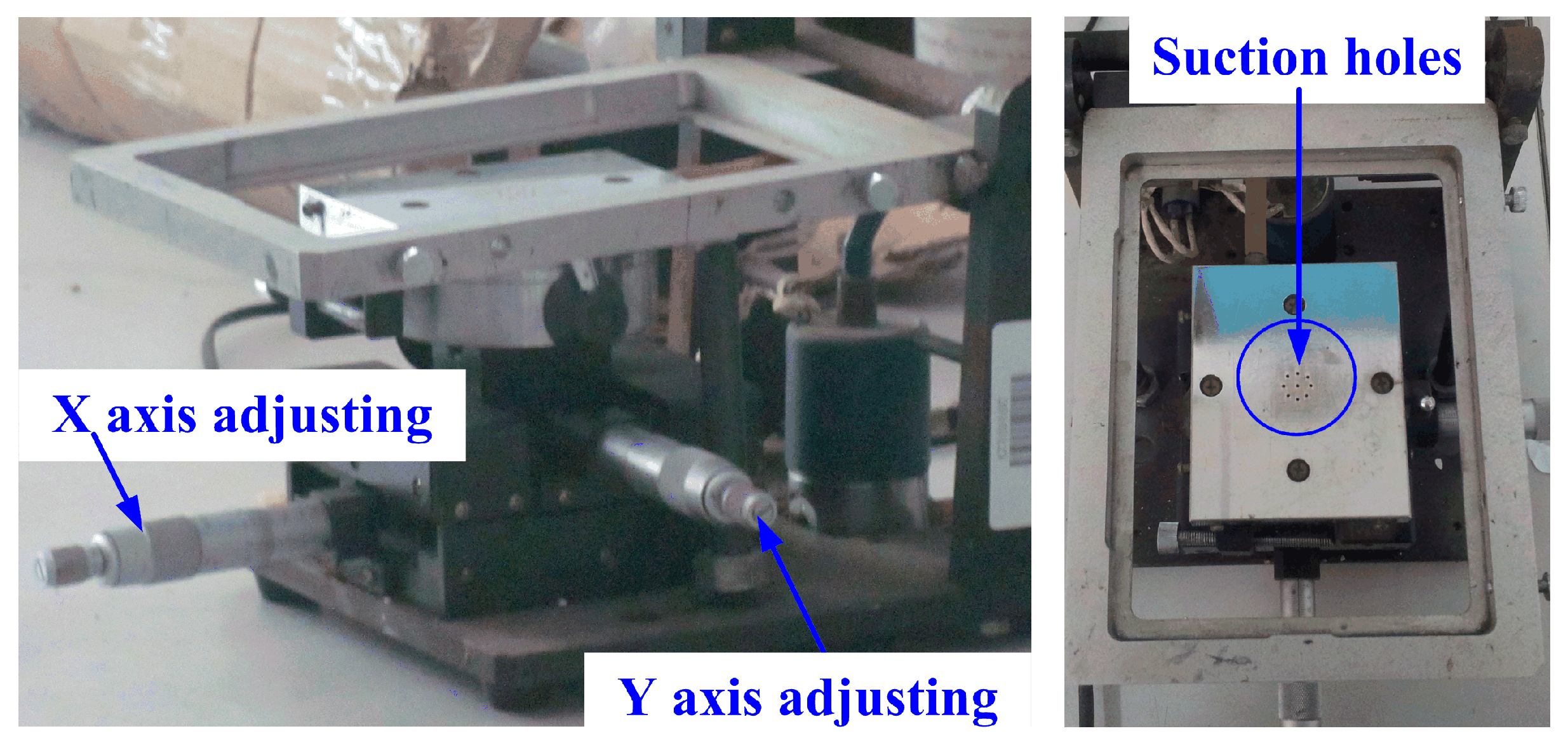
After sintering the zirconia substrate, the inductor and capacitor patterns were constructed by post-fire metallization with DuPont 6142D Ag paste. The capacitor electrode and inductor coil were printed on the surface of the zirconia substrate by a manual screen-printing platform, in which
X and
Y axes can be adjusted, as shown in
Figure 5. There are several suction holes that can rigidly fix the sensor in place. After printing the electrical pattern, the semifinished sensor was placed into a baking furnace at 200 °C for 15 min to dry the paste. Then the sensor sample was placed into a seven-zone belt furnace to metalize the inductor and capacitor. The belt of the furnace operates at a speed of 100 mm/min in accordance with sintering data
Table 3. The fabricated sensor is shown in
Figure 6. It can be observed that the sacrificial layer has volatilized completely, and the flatness of the membrane is fairly good.
Figure 3.
Fabrication process diagram of the sensor.
Figure 3.
Fabrication process diagram of the sensor.
Figure 4.
High-temperature sintering curve.
Figure 4.
High-temperature sintering curve.
Figure 5.
Manual screen-printing platform.
Figure 5.
Manual screen-printing platform.
Table 3.
Low-temperature sintering parameters.
Table 3.
Low-temperature sintering parameters.
| Zone | 1 | 2 | 3 | 4 | 5 | 6 | 7 |
|---|
| Temperature (°C) | 525 | 625 | 850 | 850 | 850 | 850 | 680 |
| Speed (mm/min) | 100 | 100 | 100 | 100 | 100 | 100 | 100 |
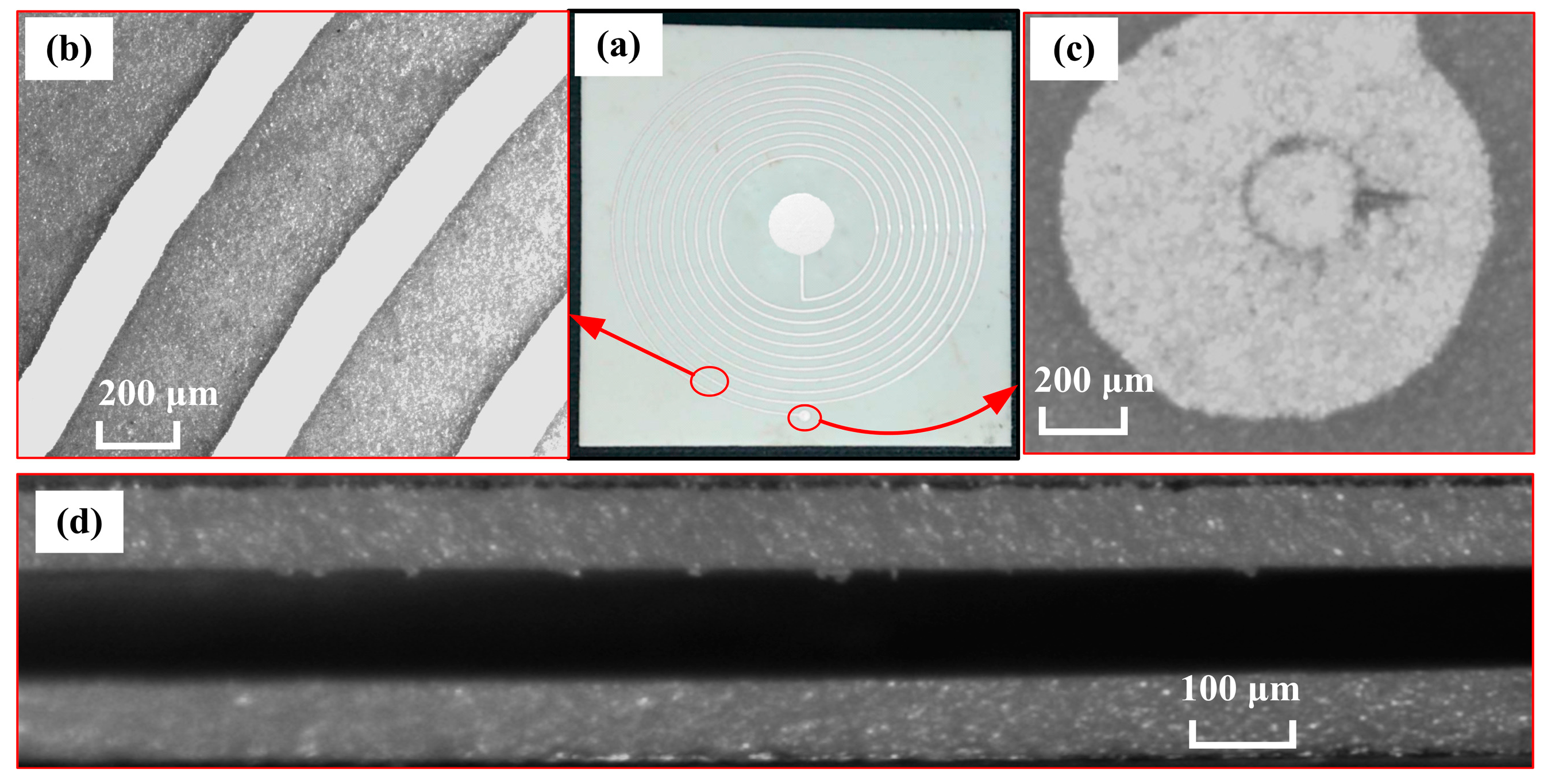
Figure 6.
(a) Photograph of the fabricated sensor (b) photomicrographs of the inductance coil; (c) via; and (d) capacitor cavity.
Figure 6.
(a) Photograph of the fabricated sensor (b) photomicrographs of the inductance coil; (c) via; and (d) capacitor cavity.
4. Experimental Section
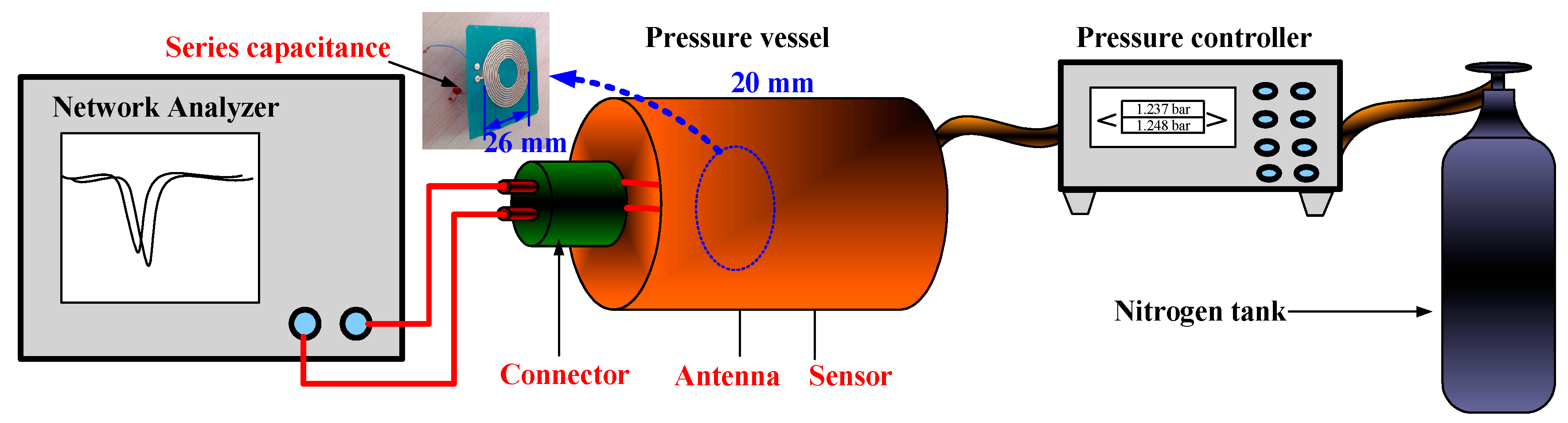
As shown in
Figure 7, the pressure calibration system consists of an Agilent E5061B (Agilent Technologies Inc., Santa Clara, CA, USA) Network Analyzer, a pressure vessel, a pressure controller, and a nitrogen tank. The reader antenna and sensor were placed into the pressure vessel, and the sensor was mounted within the near-field coupling distance (approximately 20 mm) of the antenna so that the sensor signal could be read out wirelessly. The distance between the antenna and the sensor has considerable influence on the wireless signal readout. With an increase in the coupling distance, the signal of sensor becomes weaker. However, a relatively better signal strength can be obtained when the self-resonance frequency of the antenna is closer to the resonance frequency of the sensor, even though the distance between them is constant. Therefore, a printed circuit board (PCB)-based planar spiral coil was used as a reader antenna, and a capacitor was added in series to make their resonance frequencies similar.
Figure 7.
Sensor test setup for pressure measurement.
Figure 7.
Sensor test setup for pressure measurement.
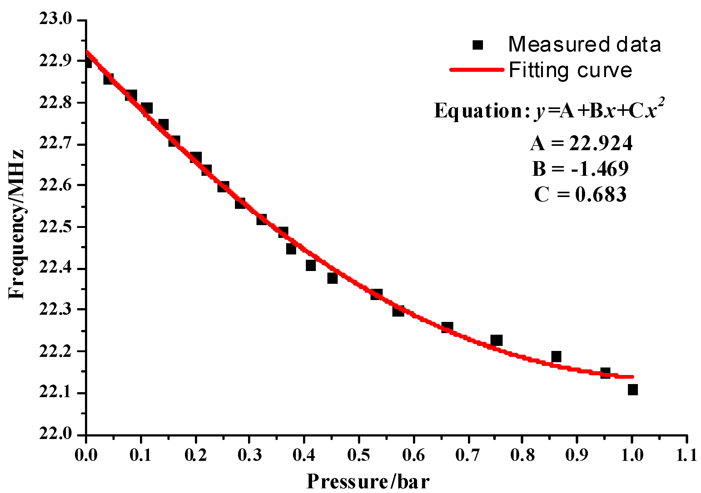
The test results are illustrated in
Figure 8, from which it is clear that the sensitivity decreases as the applied pressure increase. Within the measurement range of 0–1 bar, the sensor exhibited a considerable average sensitivity of 790 kHz/bar. It should be noted that the linearity of the sensor deteriorates with an increase in the ambient pressure because the small deflection theory is not suitable over the entire measurement range. With an increase in pressure, large deformation occurs, which will result in nonlinear deformation of the sensitive membrane and eventually lead to a nonlinear pressure response from the sensor. Undoubtedly, the sensitive membrane has some predeflection due to the fabrication process, even though the carbon membrane was used to improve the flatness of the membrane, which can greatly impair the linearity of the sensor. In
Figure 8, the measurement data points were fitted with the following quadratic function:
where
y is the frequency value corresponding to the negative peak point of the phase of the antenna, and
x is the pressure applied to the surface of the sensor.
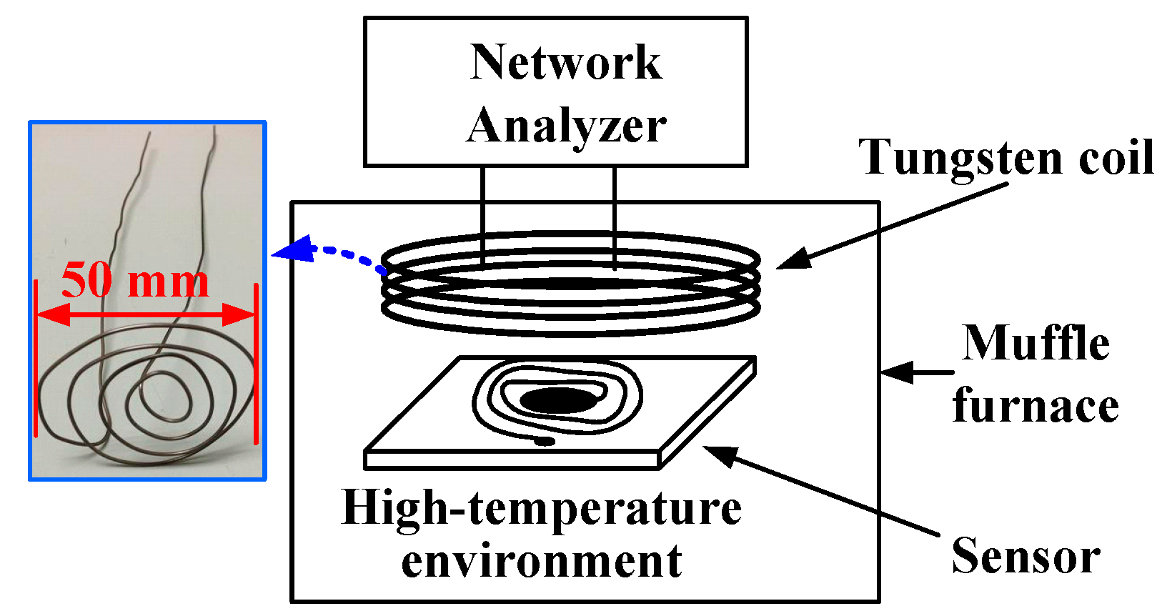
The temperature measurement setup is shown in
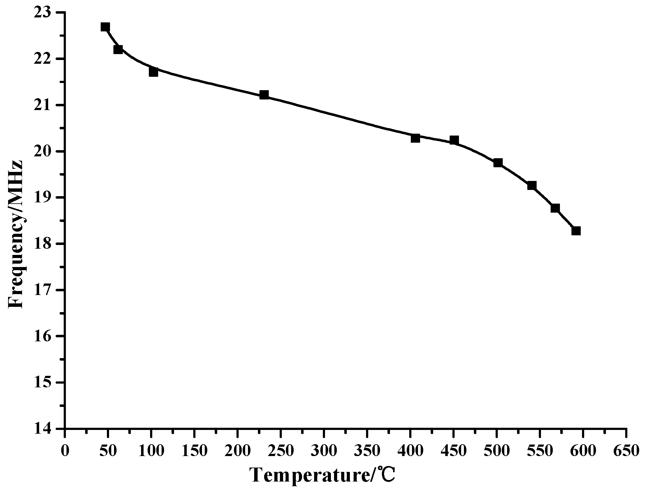
Figure 9. A muffle furnace was used to provide an environment with precise temperature control, and a tungsten filament was used as a coil for the reader antenna owing to its better stability at high temperature. The test results show that the resonant frequency of sensor decreases as the temperature increase, as show in
Figure 10. The nonlinear temperature response is mainly due to the inherent temperature-dependent dielectric constant of the zirconia ceramic. In actual application, a compensation scheme should be developed to compensate for the temperature drift so that the sensor can be used in different temperature environments. With regard to the dynamic range, the sensor proposed in this paper can operate within 1 bar at temperatures greater than 600 °C. The sensitivity and dynamic range for pressure measurement of the sensor can be extended by further adjusting the process parameters (sintering curve, lamination pressure, temperature,
etc.) to improve the flatness of the pressure-sensitive membrane. The coupling effect, which can be reflected by the value of the phase dip, became worse when the temperature increased. Furthermore, the deteriorating coupling effect is caused by the decrease in the quality factor, which is mainly due to the increase in the series resistance and capacitance, as illustrated in Equation (2).
Figure 8.
Measured frequency versus pressure.
Figure 8.
Measured frequency versus pressure.
Figure 9.
High-temperature testing system.
Figure 9.
High-temperature testing system.
Figure 10.
Measured frequency versus temperature.
Figure 10.
Measured frequency versus temperature.
The quality factor of the sensor is defined as [
14]:
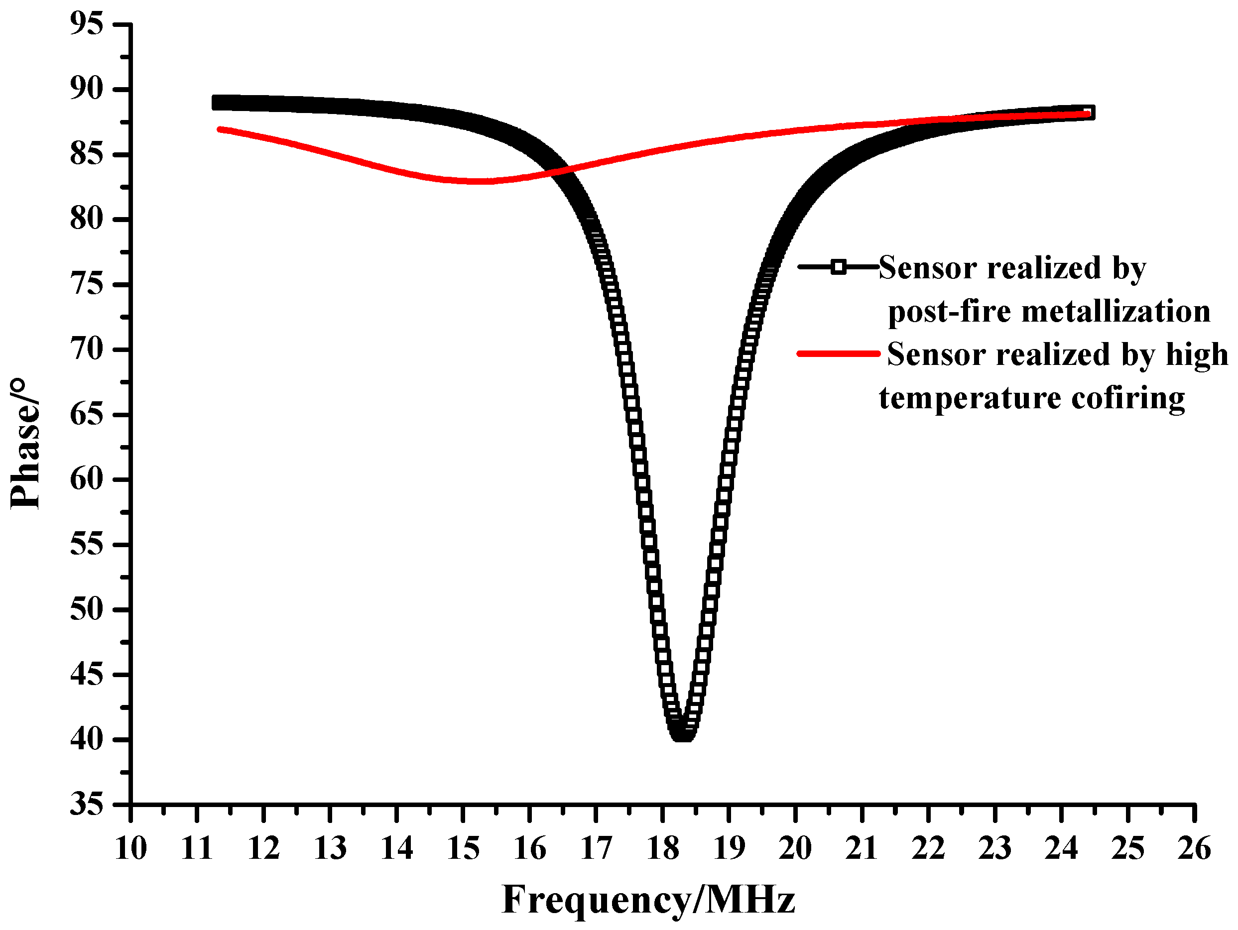
As illustrated in
Figure 11, it is clear that the sensor realized by post-fire metallization with Ag paste has a better coupling effect compared to the sensor fabricated by cofiring with Pt paste. This is because Ag has a smaller resistivity than Pt. The resistivity of Ag at room temperature is 1.58 × 10
−8 Ω·m and the resistivity of Pt is 1.1 × 10
−7 Ω·m. The resistivity of metal at a temperature
T can be expressed as:
where
ρ0 is the resistivity at room temperature, and
α is the temperature coefficient of the resistivity. The temperature coefficient for Ag and Pt are 0.0038 and 0.00374, respectively. The direct-current (DC) resistance of the Ag inductance coil at room temperature measured by a multimeter is 5.7 Ω, and corresponding resistance of the cofired sensor is 39.7 Ω. By using the Equation (3), the resistance of the sensor at 600 °C is 18.696 Ω, which is less than that of the sensor cofired with Pt paste. Therefore, the sensor fabricated by the proposed method comparatively has an excellent coupling effect at high temperature.
Figure 11.
Measured impedance phase versus frequency at 600 °C.
Figure 11.
Measured impedance phase versus frequency at 600 °C.
As shown in
Figure 11, the phase dip corresponding to the proposed sensor at 600 °C is approximately 50°, which is quite considerable compared with the phase dip of 6° for the sensor fabricated by cofiring with Pt paste. The larger phase dip of the proposed sensor at 600 °C can extend its working temperature to a higher point. Although zirconia ceramic has mechanical stability at the temperature above 600 °C, the sensor realized by co-firing cannot be used at a higher temperature owing to the weak coupling. Therefore, the proposed method can make a zirconia-ceramic-based passive pressure sensor for application in higher temperature environments.


