<?xml version="1.0" encoding="UTF-8"?>
<!DOCTYPE article PUBLIC "-//NLM//DTD Journal Publishing DTD v2.3 20070202//EN" "journalpublishing.dtd">
<article xmlns:mml="http://www.w3.org/1998/Math/MathML" xmlns:xlink="http://www.w3.org/1999/xlink" xml:lang="en" article-type="research-article">
  <front>
    <journal-meta>
      <journal-id journal-id-type="publisher-id">sustainability</journal-id>
      <journal-title>Sustainability</journal-title>
      <abbrev-journal-title abbrev-type="publisher">Sustainability</abbrev-journal-title>
      <abbrev-journal-title abbrev-type="pubmed">Sustainability</abbrev-journal-title>
      <issn pub-type="epub">2071-1050</issn>
      <publisher>
        <publisher-name>MDPI</publisher-name>
      </publisher>
    </journal-meta>
    <article-meta>
      <article-id pub-id-type="doi">10.3390/su5020400</article-id>
      <article-id pub-id-type="publisher-id">sustainability-05-00400</article-id>
      <article-categories>
        <subj-group>
          <subject>Article</subject>
        </subj-group>
      </article-categories>
      <title-group>
        <article-title>A Report of Contemporary Rammed Earth Construction and Research in North America</article-title>
      </title-group>
	  <contrib-group>
        <contrib contrib-type="author">
          <name>
            <surname>Windstorm</surname>
            <given-names>Bly</given-names>
          </name>
          <xref rid="af1-sustainability-05-00400" ref-type="aff">1</xref>
          <xref rid="c1-sustainability-05-00400" ref-type="corresp">*</xref>
        </contrib>
        <contrib contrib-type="author">
          <name>
            <surname>Schmidt</surname>
            <given-names>Arno</given-names>
          </name>
          <xref rid="af2-sustainability-05-00400" ref-type="aff">2</xref>
        </contrib>
      </contrib-group>
      
      <aff id="af1-sustainability-05-00400"><label>1 </label>North American Rammed Earth Builders Association (NAREBA) and Earth Dwell Ltd., Port Townsend, WA 98368, USA</aff>
      <aff id="af2-sustainability-05-00400"><label>2 </label>
North American Rammed Earth Builders Association (NAREBA) and Ecosol Design and Construction Ltd., Vancouver, BC, V5L 2J4, Canada; E-Mail: <email>Arno_Ecosol@telus.net</email></aff>
      <author-notes>
        <corresp id="c1-sustainability-05-00400"><label>*</label> Author to whom correspondence should be addressed; E-Mail: <email>bly@earthdwell.com</email>; Tel.: +360-385-9594; Fax: +360-385-9594.</corresp>
      </author-notes>
      <pub-date pub-type="epub">
        <day>29</day>
        <month>01</month>
        <year>2013</year>
      </pub-date>
      <pub-date pub-type="collection">
	  <month>02</month>
        <year>2013</year>
      </pub-date>
      <volume>5</volume>
      <issue>2</issue>
      <fpage>400</fpage>
      <lpage>416</lpage>
      <history>
        <date date-type="received">
          <day>01</day>
          <month>01</month>
          <year>2013</year>
        </date>
        <date date-type="rev-recd">
          <day>08</day>
          <month>01</month>
          <year>2013</year>
        </date>
        <date date-type="accepted">
          <day>18</day>
          <month>01</month>
          <year>2013</year>
        </date>
      </history>
      <permissions>
        <copyright-statement>© 2013 by the authors; licensee MDPI, Basel, Switzerland.</copyright-statement>
        <copyright-year>2013</copyright-year>
        <license xmlns:xlink="http://www.w3.org/1999/xlink" license-type="open-access" xlink:href="http://creativecommons.org/licenses/by/3.0/">
          <p>This article is an open access article distributed under the terms and conditions of the Creative Commons Attribution license (<uri>http://creativecommons.org/licenses/by/3.0/</uri>).</p>
        </license>
      </permissions>
      <abstract>
        <p>Contemporary stabilized rammed earth (SRE) draws upon traditional rammed earth (RE) methods and materials, often incorporating reinforcing steel and rigid insulation, enhancing the structural and energy performance of the walls while satisfying building codes. SRE structures are typically engineered by licensed Structural Engineers using the Concrete Building Code or the Masonry Building Code. The construction process of SRE creates structural walls of relatively high compressive strength appropriate for a broad range of heating and cooling climates. The incorporation of rigid insulation creates a high mass interior wythe that is thermally separated from the exterior, resulting in improved thermal performance. Modular aluminum reinforced formwork allows walls to be built without the use of through ties, common in concrete construction. The North American Rammed Earth Builders Association (NAREBA) collaborated with Unisol Engineering Ltd. and the British Columbia Institute of Technology (BCIT) on a battery of tests to obtain preliminary data to be used in support of engineering design. The tests included compressive strength comparisons, pull out rebar testing of both horizontally and vertically placed steel, simple beam tests, and the deflection of two composite wall columns with an insulation core and two types of reinforcing steel connections between the RE wythes.</p>
      </abstract>
      <kwd-group>
        <kwd>rammed earth</kwd>
        <kwd>stabilized rammed earth</kwd>
        <kwd>insulated rammed earth</kwd>
        <kwd>steel reinforced rammed earth</kwd>
        <kwd>contemporary rammed earth construction</kwd>
        <kwd>structural rammed earth</kwd>
        <kwd>North American Rammed Earth Builders Association (NAREBA)</kwd>
      </kwd-group>
    </article-meta>
  </front>
  <body>
    <sec sec-type="intro">
      <title>1. Introduction</title>
      <p>Stabilized rammed earth is experiencing increased interest in residential, commercial, and institutional structures around the world. In North America this is being driven by the following: (1) A growing trend toward selecting building materials that are sustainable; (2) The growing adoption of green certification programs like LEED and the International Living Future Institute’s <italic>Living Building Challenge</italic> (which includes a “Red List” of prohibited chemicals) that recognize the benefits of stabilized rammed earth; (3) An increased emphasis on selecting building materials that contribute to healthy indoor air quality; (4) The awareness that stabilized rammed earth has a substantially longer life cycle than more conventional building materials; (5) A desire to reduce the energy consumption associated with heating and cooling structures; and (6) The recognition that CO<sup>2</sup> emissions associated with buildings are a major contributor to global climate change.</p>
    </sec>
    <sec>
      <title>2. Contemporary Rammed Earth in North America</title>
      <p>Most stabilized rammed earth structures being built today in North America are based upon the traditional rammed earth methods yet possess significant and fundamental differences. These differences include: (1) A reduced clay component in the soil mix; (2) Stabilization of the rammed earth mix with portland cement, blast furnace slag and/or other pozzolans; (3) The incorporation of interstitial insulation to improve thermal performance; (4) The addition of steel reinforcing; (5) The application of the masonry and concrete code principles by structural engineers in designing the structures; and (6) The mechanization of mixing, delivery, and ramming of the soil mix.</p>
      <p>There is a simplicity and elegance to a traditional rammed earth wall. The materials embodied within it are truly raw before being transformed into a monolithic earthen wall. The embodied energy of such a wall is extremely low if the earthen material is locally sourced. If no modern equipment is used, construction of such a wall could be limited only to animal energy. Given a site with ideal soils, this traditional wall could be expected to provide a comfortable structure for generations. Unfortunately much of humanity lives on sites that do not have local access to the types of soil appropriate for unstabilized earth construction. Also, most structures built in North America must comply with local building jurisdictions, which may prefer a wall of higher compressive strength that is less susceptible to the effects of weathering and erosion; in these locations Stabilized Rammed Earth (SRE) provides a viable and more sustainable alternative to conventional building technologies.</p>
      <sec>
        <title>2.1. Building Codes</title>
        <p>There is no specific provision or mention of rammed earth in the building codes used in almost all of North America. While a few exceptions exist, most notably the U.S. state of New Mexico (Chapter 7, Part 4—The NM Earthen Building Materials Code) [<xref ref-type="bibr" rid="B1-sustainability-05-00400">1</xref>] and Tucson/Pima County, Arizona (Appendix Chapter 71, Earthen Materials Structures) [<xref ref-type="bibr" rid="B2-sustainability-05-00400">2</xref>], most local building departments have neither an understanding of rammed earth nor a local example from which to form an opinion or to create a construction and inspection protocol. This can present challenges when rammed earth is introduced to a new locale.</p>
        <p>The closest analogies that currently exist in determining the appropriate structural requirements for an SRE wall are the Concrete Building Code and the Masonry Building Code. Both standards are commonly referenced in the design and engineering of SRE walls. This approach has been supported by the most recent ASTM “Standard Guide for Design of Earthen Wall Building Systems” [<xref ref-type="bibr" rid="B3-sustainability-05-00400">3</xref>]. Currently, the application of the Concrete Building Code often results in 2500 psi (17 MPa) being specified as the minimum compressive strength (f’sre) for the SRE material. In the absence of available data on the compressive strength of SRE walls and their performance when reinforced with steel, this minimum strength has provided a level of assurance, as it is the minimum strength for concrete, and thus conforms to a standard readily accepted and understood. It is unclear if this high strength is necessary or ideal, given the ecological costs associated with cement production, but given the lack of established engineering values for SRE, it might be unavoidable for the time being. Normally this requires the addition of Portland cement and pozzolans at a combined rate of 8–10% to the earthen mix (by weight).</p>
        <p>
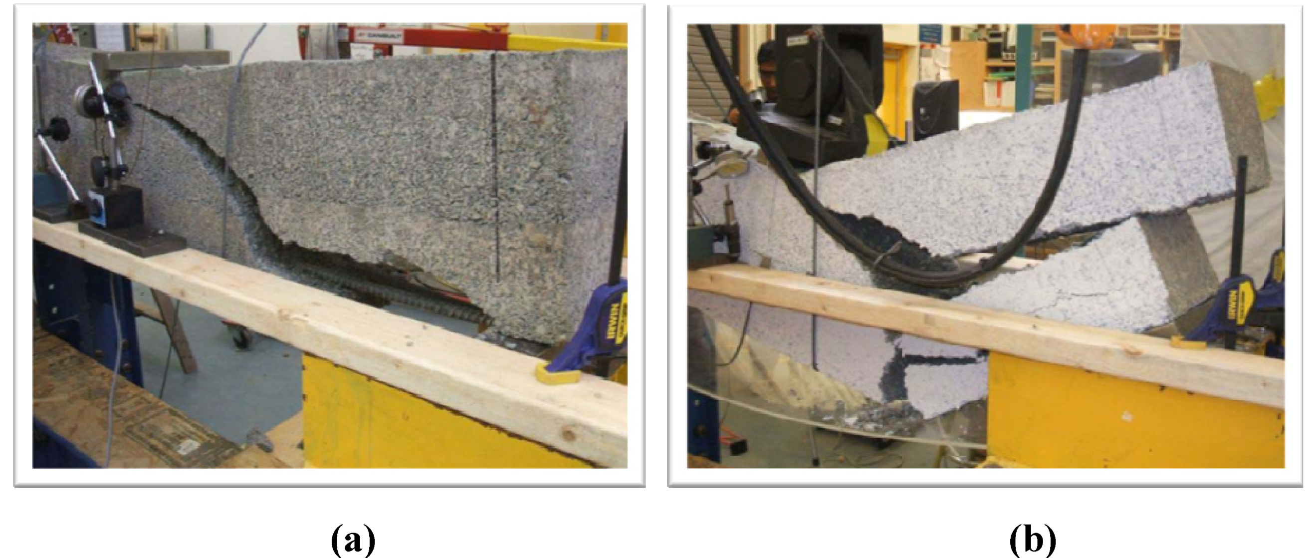
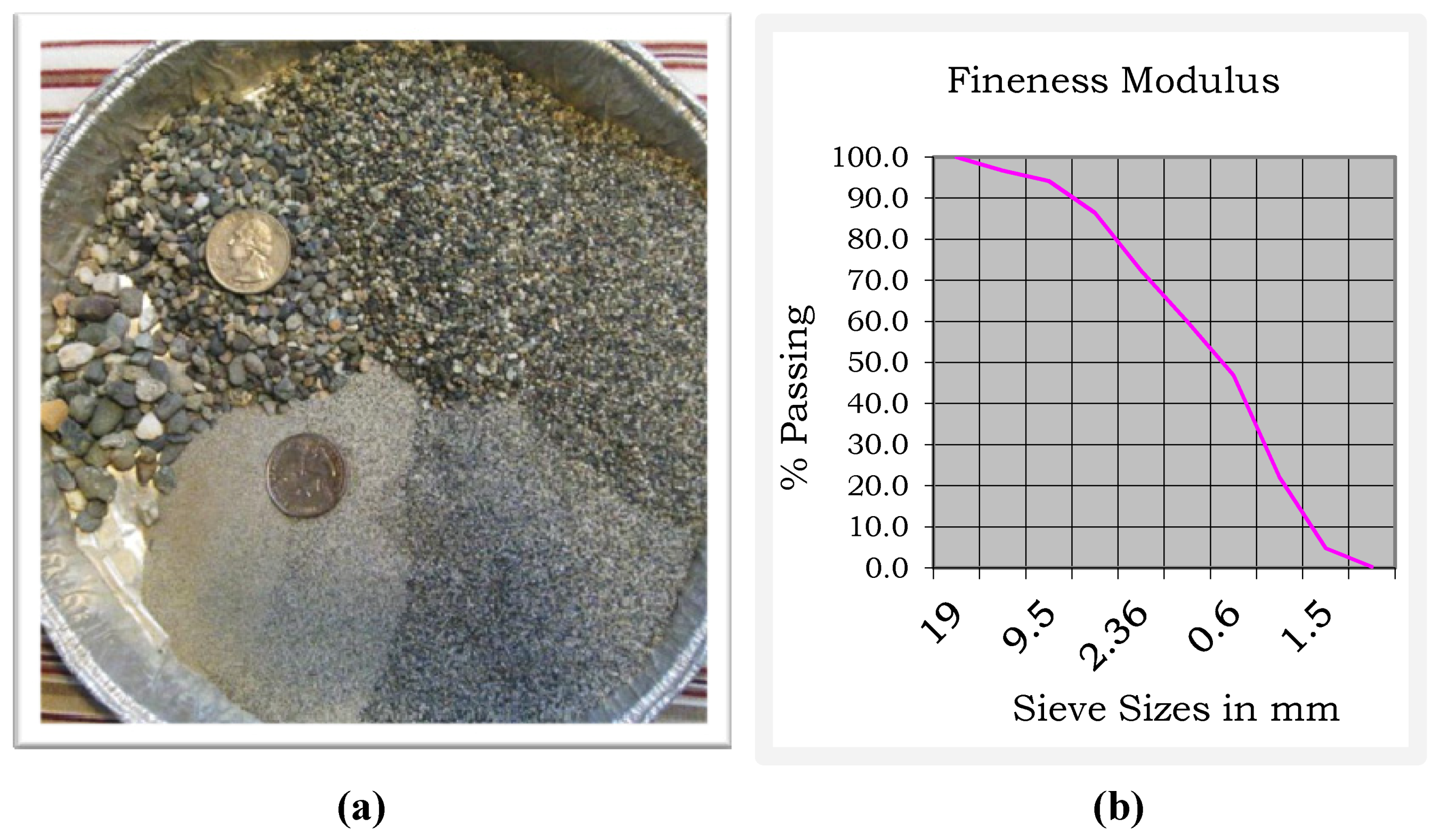
Careful selection of the earthen materials for an SRE wall is required to consistently maintain the required minimum compressive strength and to achieve that strength with the least amount of cement. Each new soil mix must be analyzed and tested for clay and silt content and the particle size distribution evaluated to determine the appropriate amount of cement required to meet the minimum specifications. Each project utilizes an earthen mix local to the building site. The earthen material is not drawn from the surface layer of topsoil, but from the material that is below the organically active layer. Therefore it does not contribute to the loss of agriculture capacity. One of the advantages of using cement and pozzolans to stabilize the mix is that it permits the use of a much wider range of sub soils than is possible with an unstabilized RE mix; this permits the use of a local earthen material to construct structural walls in locales that do not possess the appropriate soils for traditional RE. Generally speaking, these soils are lower in clay than unstabilized rammed earth, less than 15 percent by weight, and have an even particle size distribution. There are other benefits beyond the ready acceptance of the structural integrity by engineers and building departments associated with higher strength SRE mixes; one can safely assume that being of significantly higher compressive strength they will have a higher modulus of rupture and be less prone to the effects of erosion from weathering or freeze/thaw damage. When reinforced with steel, they possess ductility and can be engineered to resist the destructive forces of an earthquake. It is typically necessary to use a blend of two or more soil components to achieve the even particle size distribution appropriate for an SRE wall (see
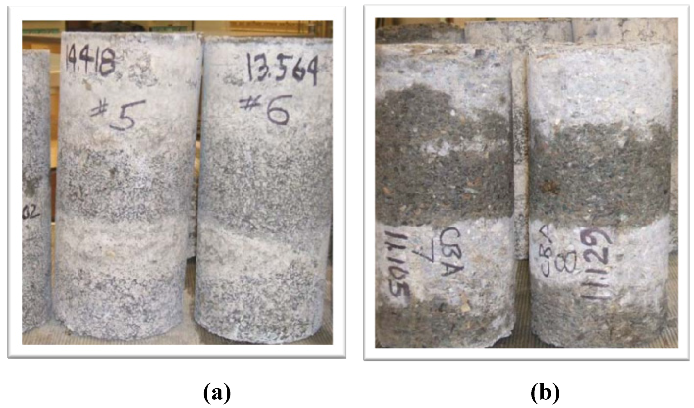
 <xref ref-type="fig" rid="sustainability-05-00400-f001">Figure 1</xref>).</p>
        <fig id="sustainability-05-00400-f001" position="float">
          <label>Figure 1</label>
          <caption>
            <p>(<bold>a</bold>) One graded soil component of a two-component stabilized rammed earth (SRE) mix design. (<bold>b</bold>) Particle size analysis for an SRE mix.</p>
          </caption>
          <graphic xmlns:xlink="http://www.w3.org/1999/xlink" xlink:href="sustainability-05-00400-g001.tif"/>
        </fig>
        <p>
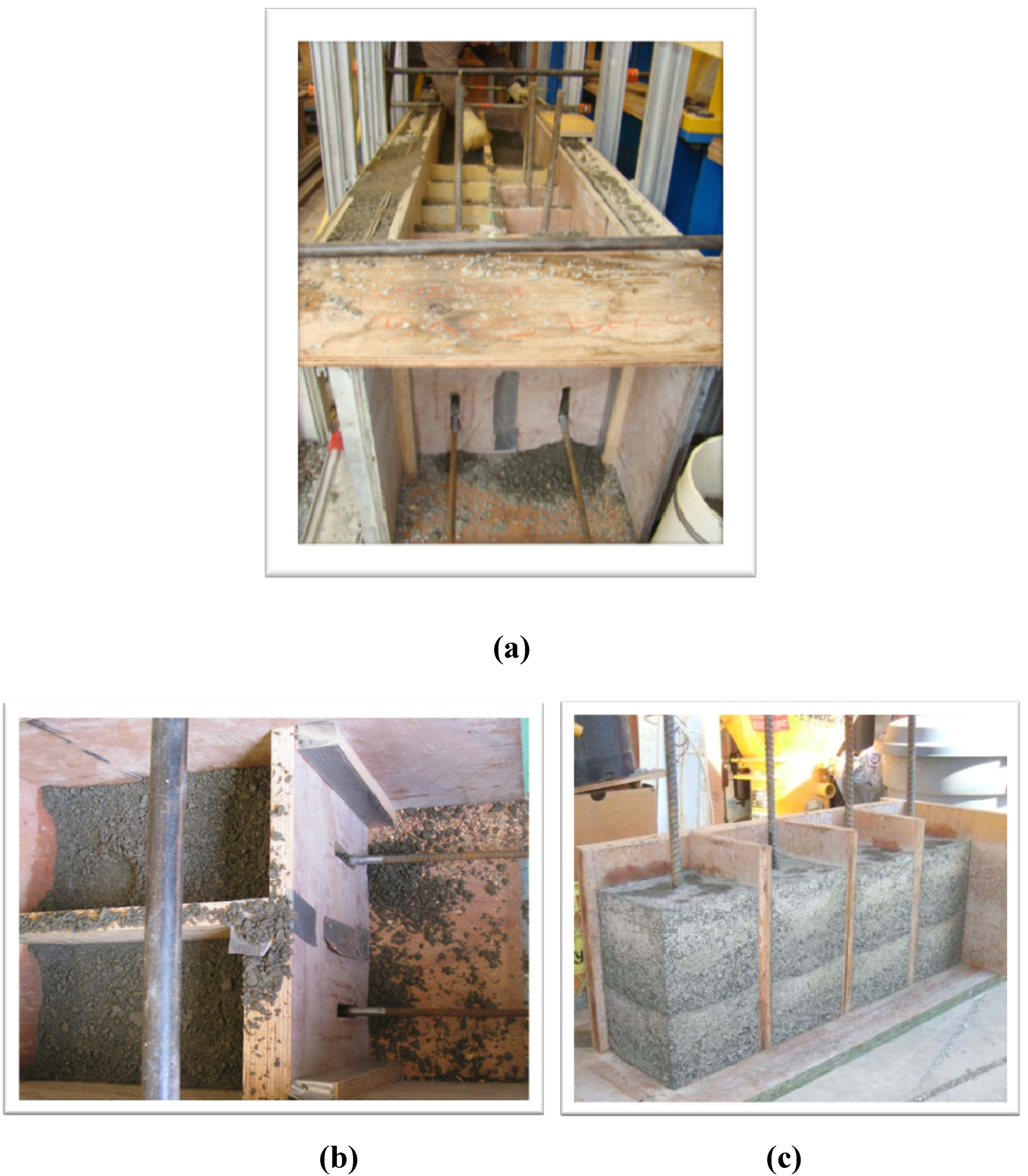
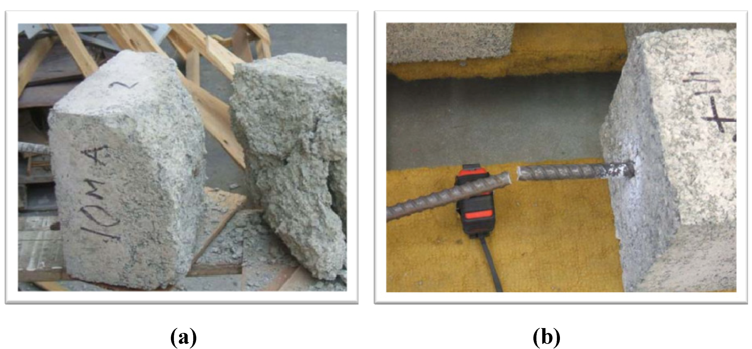
The application of the concrete code for rammed earth walls often results in steel reinforcing schedules that closely resemble those of concrete walls. Vertical steel reinforcing is continuous from the footing to the wall top and horizontal steel is placed at intervals up the wall. The CRSI “Manual of Standard Practice” is followed in the placement of reinforcing steel. There are, however, significant differences in the construction of an SRE wall and a concrete wall. The placement of the rammed earth material and steel is a more lengthy and involved process in an SRE wall. One notable difference is that the horizontal steel must be placed periodically during the earthen material placement, not prior to placement as is typical in a concrete wall, to provide access for the wall builders during construction. Unimpeded access in the wall is necessary and the typical reinforcing steel field inspection normally done prior to concrete placement must be modified, as it is not possible to place the horizontal steel prior to placing the SRE material upon which it rests. It is not practical to have a building inspector on hand for each steel placement as it occurs. Vertical steel reinforcing spacing must be maintained during the material placement and ramming, which requires ongoing attention as the soil lifts are placed and compacted. Good soil compaction around the steel is important to ensure a good bonding of the material and mobility in the wall is one necessity to ensure this.</p>
        <p>It is an interesting dilemma that SRE design and building professionals face; the walls are engineered using established concrete and masonry models, yet in order to achieve these higher strengths the walls drift further from the low carbon ideal of traditional rammed earth. It is a trade-off in that the structures have a larger initial carbon footprint due to the stabilization with 8–10 percent portland cement (though up to 50 percent may be readily replaced with recycled pozzolans, such as slag), yet the strength and resistance to weathering are improved to the point where the walls will be durable in more demanding climates and possess structural capabilities similar to a concrete wall. As one would expect, research by B.V. Venkatarama Reddy, and P. Prasanna Kumar shows that the primary source of embodied energy in an SRE wall (in this case study uninsulated and not reinforced with steel) is the energy used when making the cement. Comparatively, the energy used to actually construct an SRE wall is negligible [<xref ref-type="bibr" rid="B4-sustainability-05-00400">4</xref>]. However, the amount of energy embodied in an SRE wall compares favorably to a burnt-clay masonry wall. Not only are the hand-rammed SRE walls tested (at 8% cement content) significantly stronger than the burnt clay masonry wall; 3.38 MPa <italic>vs</italic>. 2.89 Mpa (507 psi. <italic>vs</italic>. 433psi.), but they achieve that strength with 15–25% of the embodied energy [<xref ref-type="bibr" rid="B4-sustainability-05-00400">4</xref>]. It is worth noting that strengths of 17 Mpa (2465 psi.) and greater are typical with 8–10 percent cement content and the pneumatically driven tampers used by contemporary SRE wall builders in North America. </p>
      </sec>
      <sec>
        <title>2.2. Interstitial Insulation</title>
        <p>Rammed earth has been used successfully in moderate to hot climates as the thermal mass effectively moderates the daily temperature swings, creating a comfortable living environment. Yet RE has a low thermal resistance and tests have determined its R-value to be only 0.4/inch (RSI = 0.07) [
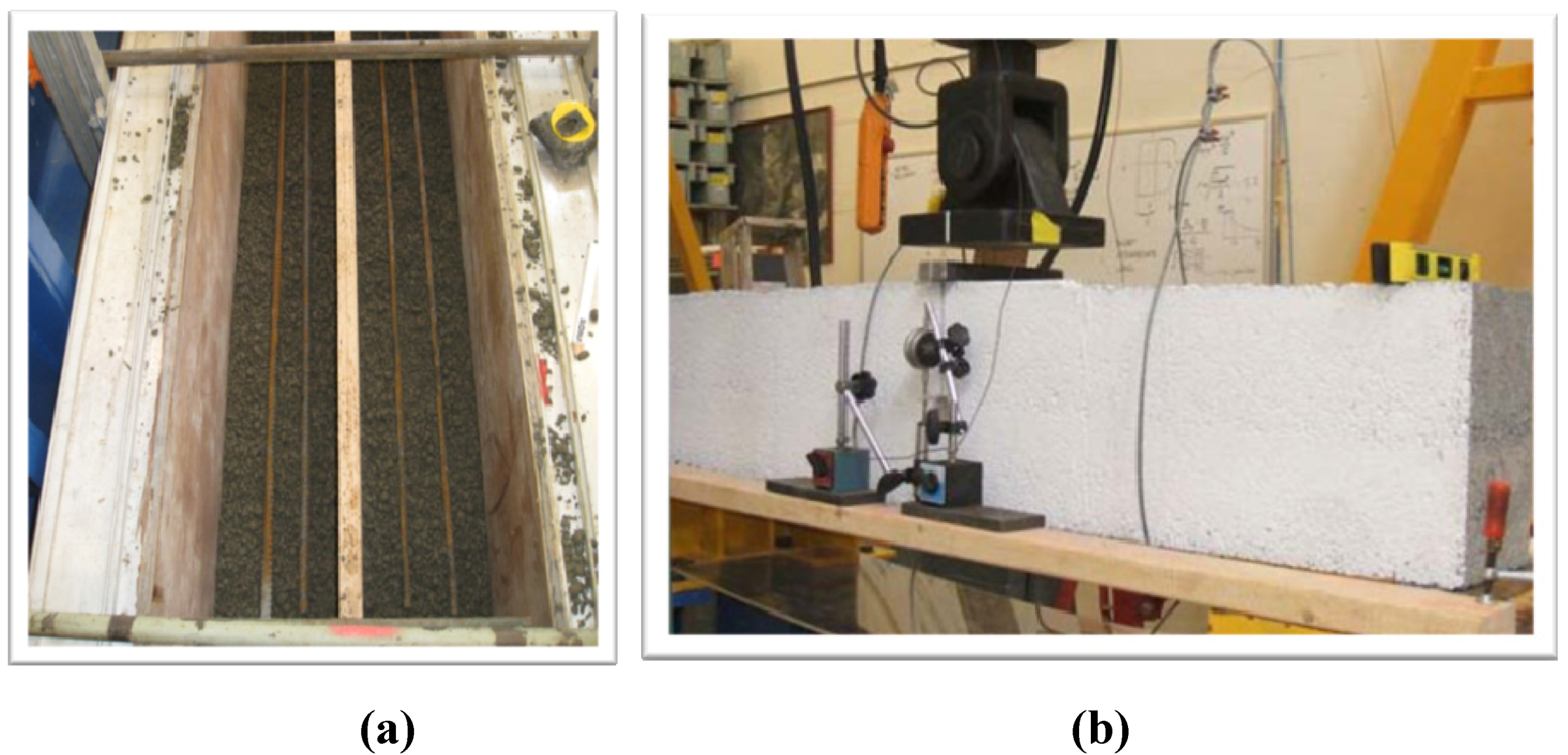
<xref ref-type="bibr" rid="B5-sustainability-05-00400">5</xref>]. It is the introduction of interstitial insulation that has allowed rammed earth to meet the increasingly stringent energy codes in a broad range of climates where both the maximum and minimum daily temperatures are significantly above or below the desired indoor temperatures for weeks and months a time. Thermal conductivity tests, conducted by M.A. Hall, on composite SRE walls with extruded polystyrene (XPS) insulation demonstrated that the combination of a high mass wall with the low conductivity of foam insulation resulted in a wall that had a lower thermal conductivity than a solid earth wall or an earthen wall with insulation located at only the internal or external face, while improving the mass performance of the wall as a whole [<xref ref-type="bibr" rid="B6-sustainability-05-00400">6</xref>]. These composite SRE walls exhibited excellent thermal properties suitable for a broad range of heating and cooling climates, and could be expected to significantly outperform an uninsulated earthen wall [<xref ref-type="bibr" rid="B6-sustainability-05-00400">6</xref>]. Detailed correctly, insulated rammed earth structures are extremely airtight, making a mechanical ventilation system necessary to maintain healthy indoor air quality. </p>
        <p>There are three types of insulation typically used in RE structures in North America. Extruded polystyrene (XPS) is commonly used in the US and Canada. It has a perm rating of 1.1/inch (0.00071 m<sup>2)</sup> and an R-value of 5/in. (RSI 0.88) It has a compressive strength of 25 psi (0.17 Mpa) [
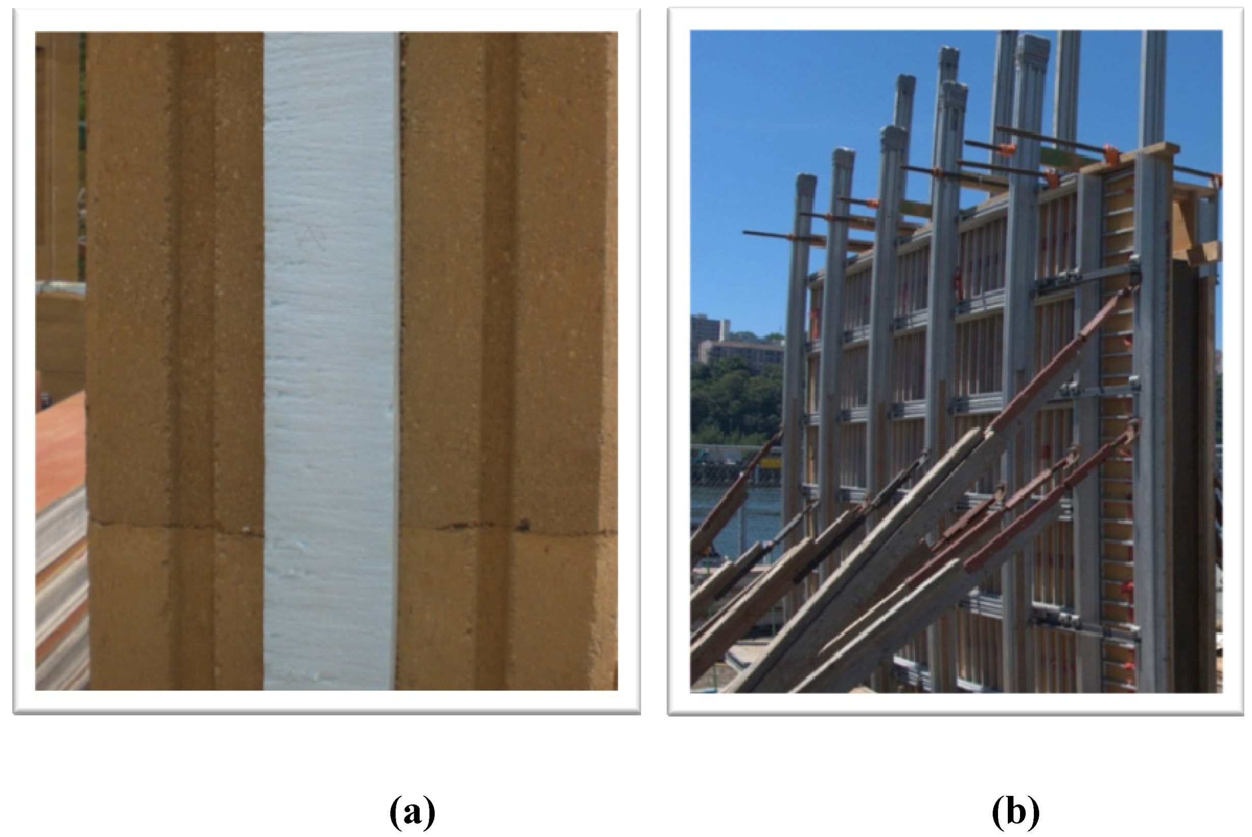
<xref ref-type="bibr" rid="B7-sustainability-05-00400">7</xref>]. XPS is commonly available and is dense enough to withstand the compaction forces it is subjected to during wall construction without deformation or loss of thermal performance (see <xref ref-type="fig" rid="sustainability-05-00400-f002">Figure 2</xref>). It is a closed cell foam that has a natural “skin”, which makes the board resistant to moisture. It is designed specifically for use in masonry wall environments. </p>
        <p>Mineral wool fiber insulation, made from basalt rock and recycled slag, are used both in Canada and the U.S. It has an R-value of 4.3/in. (RSI 0.76) and a density of 3.4 lbs/ft<sup>3</sup> (0.05 g/cm<sup>3</sup>). This insulation is also designed for use in a masonry wall cavity and has a perm rating of 27.2/in. (0.018/m<sup>2</sup>) [<xref ref-type="bibr" rid="B8-sustainability-05-00400">8</xref>]. When used interstitially in a rammed earth wall it is prone to compression during the ramming process and may suffer some reduction in thermal performance as a result. Rockwool insulations have the added benefit of scoring LEED points; a consideration on LEED certified projects. It can be more difficult to obtain in some regions. Comparatively, mineral wool insulations can be more difficult to work with because the mineral wool fibers can be an irritant to wall builders during construction.
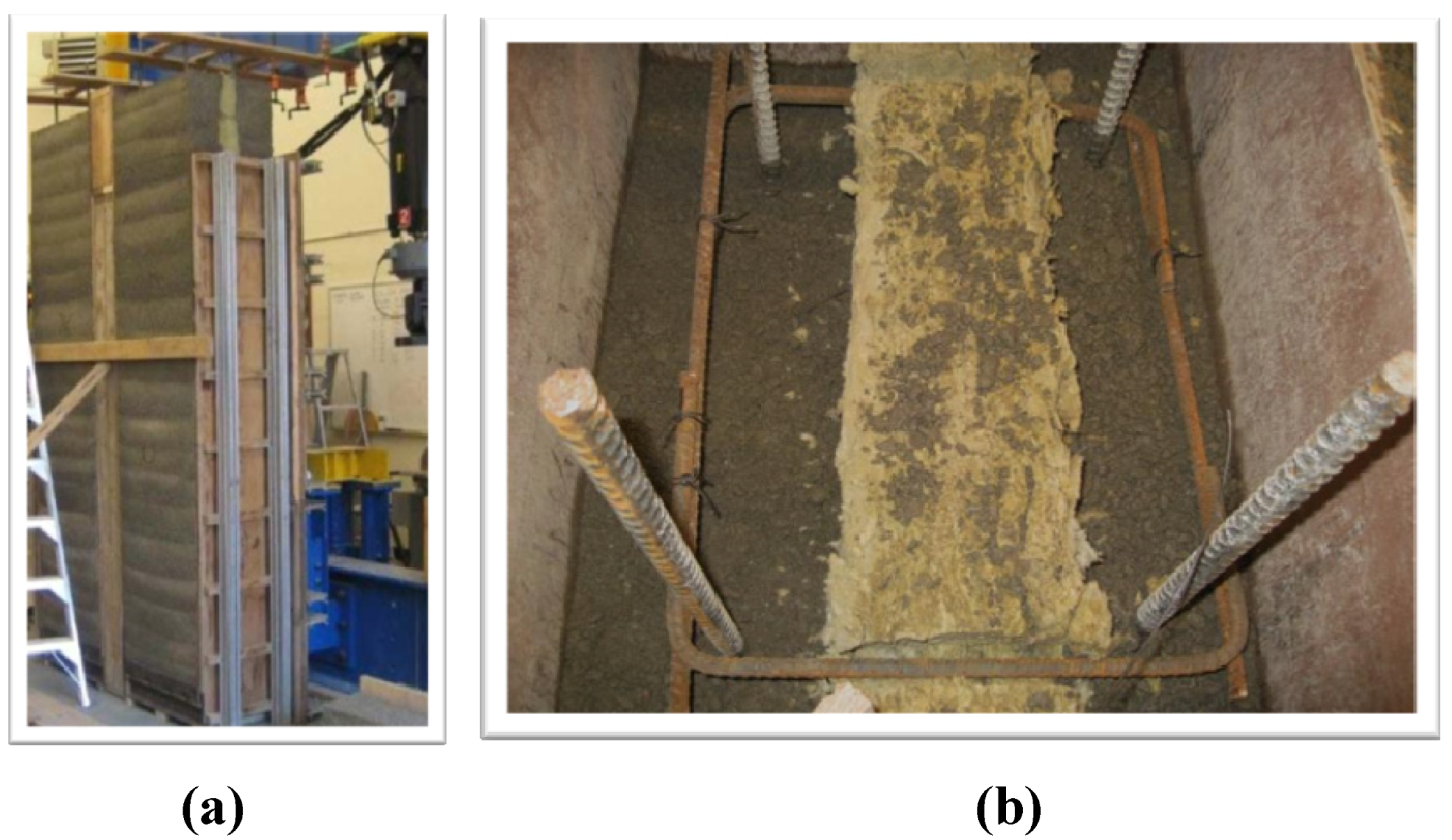
</p>
		<fig id="sustainability-05-00400-f002" position="float">
          <label>Figure 2</label>
          <caption>
            <p>(<bold>a</bold>) Extruded polystyrene (XPS) foam in an SRE wall. (<bold>b</bold>) A North American Rammed Earth Builders Association (NAREBA) Formwork (fisheye lens).</p>
          </caption>
          <graphic xmlns:xlink="http://www.w3.org/1999/xlink" xlink:href="sustainability-05-00400-g002.tif"/>
        </fig>
        
        <p>Polyisocyanurate insulation (PIR), a member of the urethane family of chemicals, is a closed cell foam also used interstitially. According to the manufacturer, at 7.4/in. (RSI 1.3), it has the highest initial R-value of rigid insulations [<xref ref-type="bibr" rid="B9-sustainability-05-00400">9</xref>]. This elevated R-value is partially the result of the blowing agent trapped in the foam during production. Over time this gasses off causing a deterioration of the R-value. This process, known as “thermal drift”, may be slowed by the inclusion of a foil facing on the product, but its long term R-value is rated at 6.5/in. (RSI 1.14) It has a compressive strength of 25 psi (0.17 Mpa) and a perm rating of 0.03/in (5.574 e–07 m<sup>2</sup>) [<xref ref-type="bibr" rid="B9-sustainability-05-00400">9</xref>]. Careful selection of PIR insulation is required as not all types are appropriate for a masonry wall application. </p>
        <p>A fourth insulation, not yet used on a rammed earth project to date, but which shows great promise as an ecological alternative to the petro-chemical based rigid foams, is Biofoam. It is non-toxic polyurethane rigid foam developed from plants. It does not contain the halogenated flame retardants used in other rigid foams. It also lacks the added urea formaldehyde used in rock wool insulations. It contains none of the International Living Future Institute’s “Red Listed” chemicals [<xref ref-type="bibr" rid="B10-sustainability-05-00400">10</xref>]. Biofoam is made with plant-based polyols and MDI (methylene-based isocyanate). Bio based polyols replace from 80–100% of the petroleum based polyols, resulting in insulation with a significantly lower carbon footprint. The plant based polyols require 60% less energy to produce than the petroleum based polyols [<xref ref-type="bibr" rid="B10-sustainability-05-00400">10</xref>]. According to the manufacturer, there are no toxic chemicals involved in the production of Biofoam. The harmful chemical MDA, a building block in pMDI, is found in traditional polyurethane, but is not present in Biofoam. The R-value of Biofoam is 4.6/in (RSI .81) and it has a water absorption rate of less than 0.04% [<xref ref-type="bibr" rid="B10-sustainability-05-00400">10</xref>]. With a performance and durability comparable to XPS and Polyisocyanurate, Biofoam currently offers a promising ecological alternative to traditional rigid foam insulation. </p>
      </sec>
      <sec>
        <title>2.3. Formwork</title>
        <p>The formwork currently used in the construction of RE walls varies widely. Wood framed and plywood faced formworks have been and continue to be used. They are frequently used on smaller projects or custom RE elements that require atypical form shapes. Commercial concrete forms have been modified to provide aluminum based support systems for the forming plywood. This approach may require the significant modification of the forms as they are designed to be used with a through tie system, which may not be utilized on many projects, especially projects using an interstitial insulation, as this impedes the placement of ties. These forms do, however, provide a reusable formwork system that can deliver excellent results. Proprietary SRE forms have been developed in Canada but they have proven to be unnecessarily complicated to use and exceptionally expensive to produce. </p>
        <p>The forces created during the repeated compaction of lifts of earth inside a form are extreme. A forming system must be capable of withstanding this in order to create walls that are plumb and straight. Additionally, the benefits of an efficient forming system are not to be underestimated (see <xref ref-type="fig" rid="sustainability-05-00400-f002">Figure 2</xref>).</p>
      </sec>
    </sec>
    <sec>
      <title>3. Collaborative Stabilized Rammed Earth (SRE) Testing</title>
      <p>Tests conducted at the British Colombia Institute of Technology (BCIT), designed and constructed in collaboration with Thor A. Tandy, PE of Unisol Engineering, and The North American Rammed Earth Builders Association (NAREBA), with funding provided by the Cement Association of Canada, reveal characteristics of steel-reinforced SRE walls that begin to shed light on the interaction of the SRE material and the steel reinforcing configurations currently used by wall builders. It is important to emphasize that the test sample size is small and the results must be interpreted within that context. None the less, it is the first significant testing of a full-size insulated SRE column and the results are revealing about the nature of the materials. The tests included: (1) Compression testing of the soil mix; (2) Vertical rebar pull out tests; (3) Horizontal rebar pull out tests; (4) Flexural beam tests; and (5) Out of plane bending of vertical insulated columns with two different reinforcing steel stirrup configurations. These tests were specifically designed to simulate the methods of construction typically used by NAREBA builders in the construction of insulated and uninsulated SRE projects. </p>
      <sec>
        <title>3.1. Test Soil Mix Design</title>
        <p>The soil mix was locally obtained and was composed of two components blended in equal amounts, then mixed in a drum mixer. The combined material was 14 mm (5/8”) minus with a Fineness Modulus of 4.02; the clay content was under 7% by weight. The portland cement (Type II) content was 10% by weight. The water content was determined by performing a “ball test”, (in the manner typically used in the field), in which the material will form a cohesive ball which shatters when dropped from waist height (6–7% moisture content). An analysis of six of the mix samples showed that the average moisture content and water to cement ratio for these samples was 6.644% and 0.60 respectively. </p>
        <p>The material for all test samples was compacted using a pneumatic tamper with a 64 mm (2.5in) or 76 mm (3in) head [<xref ref-type="bibr" rid="B11-sustainability-05-00400">11</xref>].</p>
      </sec>
      <sec>
        <title>3.2. Compressive Strength Testing</title>
        <p>Two types of samples were prepared to evaluate the compressive strength (f’sre) of the material. One series of samples was cast (rammed) in PVC tubes in the same manner that quality control samples are cast in the field. A second series was cored from SRE elements constructed in the same manner that SRE walls are made. This permits a comparative analysis of the f’sre of cast cylinders with material in a typical wall. </p>
        <p>This testing was accomplished using cast cylinders (see <xref ref-type="fig" rid="sustainability-05-00400-f003">Figure 3</xref>a) prepared by ramming the material into thirteen 150 mm (6 in) diameter by 300 mm (12 in) tall cylinders in PVC pipe in two successive six inch lifts [<xref ref-type="bibr" rid="B11-sustainability-05-00400">11</xref>].</p>
        <fig id="sustainability-05-00400-f003" position="float">
          <label>Figure 3</label>
          <caption>
            <p>(<bold>a</bold>) PVC cast cylinders; (<bold>b</bold>) Cylinders cored from test blocks. </p>
          </caption>
          <graphic xmlns:xlink="http://www.w3.org/1999/xlink" xlink:href="sustainability-05-00400-g003.tif"/>
        </fig>
        <p>Twelve cylinders (see <xref ref-type="fig" rid="sustainability-05-00400-f003">Figure 3</xref>b) were created by coring into 480 mm (19 in) wide by 600 mm (24 in) long by 300 mm (12 in) deep and 200 mm (8 in) wide by 600 mm (24 in) long by 300 mm (12 in) deep rectangular blocks that were formed and rammed in a manner consistent with typical RE walls and insulated RE walls. The material in these samples was also rammed in two six inch lifts [<xref ref-type="bibr" rid="B11-sustainability-05-00400">11</xref>].</p>
        <p>The compression tests were performed at a rate of 0.35–0.55 MPa/s (50–80 psi/s) on a 400 Kip Forney machine. The average strength of the rammed cylinder samples at six days was 12 MPa (1741 psi). This increased to 16 MPa (2221 psi) at 12 days. The samples cored from the blocks yielded strength of 15 MPa (2176 psi) at 16 days [<xref ref-type="bibr" rid="B12-sustainability-05-00400">12</xref>].</p>
      </sec>
      <sec>
        <title>3.3. Rebar Pull Out Tests</title>
        <p>Rebar pull out testing was conducted on both vertically embedded bars (VPO) and horizontally embedded bars (HPO) in two phases of testing. Three diameters of deformed bar were tested: 10M (#3), 15M (#5), and 20M (#6). In Phase I two samples of each bar were oriented vertically. Additionally two samples of 10M bar were oriented horizontally (see <xref ref-type="fig" rid="sustainability-05-00400-f004">Figure 4</xref>). Phase II was conducted to compensate for anomalies present in Phase I. In this phase, two samples of 15M (#5) and 20M (#6) rebar placed vertically, were rammed.</p>
        <fig id="sustainability-05-00400-f004" position="float">
          <label>Figure 4</label>
          <caption>
            <p>(<bold>a</bold>) Phase I VPO and HPO test samples during production. (<bold>b</bold>) Phase I HPO test samples during production. (<bold>c</bold>) Phase I VPO test samples during production.</p>
          </caption>
          <graphic xmlns:xlink="http://www.w3.org/1999/xlink" xlink:href="sustainability-05-00400-g004.tif"/>
        </fig>
        <p>A synopsis of the results from Phase I and Phase II provides the most accurate assessment of the bond strength. The VPO 15M (#5) samples in Phase I were damaged in handling and were unable to provide useful data. Phase II was designed to compensate for the lost data associated with these samples. The Phase II tests of the 15M (#5) VPO bars provided consistent results. The steel reached yield in both tests and the bond strength was 2.9 MPa (420 psi) [<xref ref-type="bibr" rid="B12-sustainability-05-00400">12</xref>].</p>
        <p>The 20M (#6) bars demonstrated the greatest bond strength values for the various rebars in both Phase I and II. They reached yield in Phase I with bond strengths over 5 MPa (725 psi) and in Phase II pulled out of the sample after reaching bond strength of over 4 MPa (600 psi) [<xref ref-type="bibr" rid="B12-sustainability-05-00400">12</xref>].</p>
        <p>The two 10M (#4) VPO bars tested with a high degree of variability. The first bar reached yield with bond strength in excess of 3 Mpa (435 psi) and the second pulled out in excess of 1.5 Mpa (217.5 psi). The results of the two 10M (#4) HPO bars were consistent with a bond strength slightly less than 2.5 MPa (363psi). One sample reached yield and one pulled out (see <xref ref-type="fig" rid="sustainability-05-00400-f005">Figure 5</xref>) [<xref ref-type="bibr" rid="B12-sustainability-05-00400">12</xref>].</p>
        <fig id="sustainability-05-00400-f005" position="float">
          <label>Figure 5</label>
          <caption>
            <p>(<bold>a</bold>) 10M (#4) Sample after testing. (<bold>b</bold>) Bar failure in Pull Out test.</p>
          </caption>
          <graphic xmlns:xlink="http://www.w3.org/1999/xlink" xlink:href="sustainability-05-00400-g005.tif"/>
        </fig>
      </sec>
      <sec>
        <title>3.4. Simple Beam Flexural Tests</title>
        <p>Simple beam tests were conducted on two beams measuring 200 mm (8 in) in width by 300 mm (10 in) in depth by 1500 mm (60 in) in length (see <xref ref-type="fig" rid="sustainability-05-00400-f006">Figure 6</xref>). One was constructed with two 10M (#4) deformed rebars and the other with two 15M (#5) deformed rebars. The beams (see <xref ref-type="fig" rid="sustainability-05-00400-f006">Figure 6</xref>) were subjected to a 1 kN/minute (225 lbf) load initially and 2 kN/minute (450 lbf) load after 75 kN (16861 lbf) was reached, using a modified three point loading system [<xref ref-type="bibr" rid="B12-sustainability-05-00400">12</xref>]. </p>
        <fig id="sustainability-05-00400-f006" position="float">
          <label>Figure 6</label>
          <caption>
            <p>(<bold>a</bold>) Rebar placement in RE beams. (<bold>b</bold>) Beam 2 with 1420 mm (54 in) clear span. </p>
          </caption>
          <graphic xmlns:xlink="http://www.w3.org/1999/xlink" xlink:href="sustainability-05-00400-g006.tif"/>
        </fig>
        <p>Test Beam 1 was reinforced with two 15M (#5) bars. No initial flexural cracks were observed and the beam failed at a peak shear load of 78 kN (17535.10 lbf). The deflection at the peak was approximately 5.5 mm (0.22 in). The beam failed in shear (see <xref ref-type="fig" rid="sustainability-05-00400-f007">Figure 7</xref>) [<xref ref-type="bibr" rid="B12-sustainability-05-00400">12</xref>].</p>
        <p>Test Beam 2 was reinforced with two 10M (#3) rebars. The first crack was recorded at 38kN (8543 lbf) and the ultimate failure was abrupt at 60 kN (13489 lbf) with a deflection of approximately 4.5 mm (0.17 in). This beam also failed in shear (see <xref ref-type="fig" rid="sustainability-05-00400-f007">Figure 7</xref>) [<xref ref-type="bibr" rid="B12-sustainability-05-00400">12</xref>].</p>
        <p>The load to deflection profile for the two beam tests are shown in <xref ref-type="fig" rid="sustainability-05-00400-f008">Figure 8</xref>, <xref ref-type="fig" rid="sustainability-05-00400-f009">Figure 9</xref> respectively.</p>
		<fig id="sustainability-05-00400-f007" position="float">
          <label>Figure 7</label>
          <caption>
            <p>(<bold>a</bold>) Test Beam 1 at failure. (<bold>b</bold>) Test Beam 2 at failure. </p>
          </caption>
          <graphic xmlns:xlink="http://www.w3.org/1999/xlink" xlink:href="sustainability-05-00400-g007.tif"/>
        </fig>
        
        <fig id="sustainability-05-00400-f008" position="float">
          <label>Figure 8</label>
          <caption>
            <p>Flexure Test-Beam 1 results (2)-15M (#5) Rebars [<xref ref-type="bibr" rid="B12-sustainability-05-00400">12</xref>] Note; Deflection sensor 1 (in red) was considered to be erroneous as the beam was not perfectly seated and the deflection initially decreased. </p>
          </caption>
          <graphic xmlns:xlink="http://www.w3.org/1999/xlink" xlink:href="sustainability-05-00400-g008.tif"/>
        </fig>
        <fig id="sustainability-05-00400-f009" position="float">
          <label>Figure 9</label>
          <caption>
            <p>Flexure Test-Beam 2 results - (2)-10M (#4) Rebars [<xref ref-type="bibr" rid="B12-sustainability-05-00400">12</xref>].</p>
          </caption>
          <graphic xmlns:xlink="http://www.w3.org/1999/xlink" xlink:href="sustainability-05-00400-g009.tif"/>
        </fig>
      </sec>
      <sec>
        <title>3.5. Composite Wall Column Out of Plane Bending</title>
        <p>Two composite SRE walls columns, representative of a typical insulated SRE wall (see <xref ref-type="fig" rid="sustainability-05-00400-f010">Figure 10</xref>) were constructed using two different deformed 10M (#3) stirrup configurations, which are representative of steel configurations used by SRE builders in the field. The columns measured 600 mm (24 in) in width by 450 mm (18 in) in depth by 2650 mm (106 in) in height and each had two full height deformed 20M (#6) vertical rebars in each wythe (four per column) of SRE (see <xref ref-type="fig" rid="sustainability-05-00400-f010">Figure 10</xref>, <xref ref-type="fig" rid="sustainability-05-00400-f011">Figure 11</xref>). The wythes of SRE were separated by a 125 mm (5 in) core of mineral wool (Roxul 80) insulation that compressed approximately 13 mm (0.5 in) during material compaction [<xref ref-type="bibr" rid="B11-sustainability-05-00400">11</xref>].</p>
        <fig id="sustainability-05-00400-f010" position="float">
          <label>Figure 10</label>
          <caption>
            <p>(<bold>a</bold>) Wall columns stripped of forms. (<bold>b</bold>) Steel configuration in Column I.</p>
          </caption>
          <graphic xmlns:xlink="http://www.w3.org/1999/xlink" xlink:href="sustainability-05-00400-g010.tif"/>
        </fig>
        <p>The horizontal steel configuration of column I was a “U” shaped stirrup placed with a horizontal rebar every 600 mm (24 in) up the height of the wall (see <xref ref-type="fig" rid="sustainability-05-00400-f010">Figure 10</xref>). This configuration is simple to place and requires minimal cutting of the insulation.</p>
        <p>The steel configuration in Column II was a more complex diagonal tie that hooked behind the vertical steel (see <xref ref-type="fig" rid="sustainability-05-00400-f011">Figure 11</xref>). The diagonal ties were placed with the horizontal steel every 600 mm (24 in) along the height of the wall. This steel configuration is more challenging and time consuming to place and requires more notching of the insulation.</p>
		<fig id="sustainability-05-00400-f011" position="float">
          <label>Figure 11</label>
          <caption>
            <p>(<bold>a</bold>) Steel Configuration in column II (wood rebar supports removed during construction). (<bold>b</bold>) A column under deflection (painted for improved crack visibility). </p>
          </caption>
          <graphic xmlns:xlink="http://www.w3.org/1999/xlink" xlink:href="sustainability-05-00400-g011.tif"/>
        </fig>
        
        <p>The columns were constructed on steel bases (see <xref ref-type="fig" rid="sustainability-05-00400-f012">Figure 12</xref>b) that permitted them to be hoisted onto an apparatus and supported horizontally at the base and cap. The load was applied along the entire face of the column via a steel channel attached to an actuator (see <xref ref-type="fig" rid="sustainability-05-00400-f011">Figure 11</xref>b). Both columns were tested in displacement control. Dial gauges and two LVDTs were placed mid-height, along the width of the back face of each column, to record the deflection (see <xref ref-type="fig" rid="sustainability-05-00400-f012">Figure 12</xref>a) [<xref ref-type="bibr" rid="B12-sustainability-05-00400">12</xref>].</p>
        <fig id="sustainability-05-00400-f012" position="float">
          <label>Figure 12</label>
          <caption>
            <p>(<bold>a</bold>) Cracks visible and LVDTs. (<bold>b</bold>) A test Column after removal from lab.</p>
          </caption>
          <graphic xmlns:xlink="http://www.w3.org/1999/xlink" xlink:href="sustainability-05-00400-g012.tif"/>
        </fig>
        <p>Column 1 was loaded to a maximum deflection of more than 30 mm (1.2 in) at a load of just under 60 kN (13489 lbf). [<xref ref-type="bibr" rid="B12-sustainability-05-00400">12</xref>] Cracks developed during this loading and were documented. The load— displacement graph for column 1 is shown in <xref ref-type="fig" rid="sustainability-05-00400-f013">Figure 13</xref>.</p>
        <fig id="sustainability-05-00400-f013" position="float">
          <label>Figure 13</label>
          <caption>
            <p>Load (kN) <italic>vs</italic>. Displacement (mm) for Column I [<xref ref-type="bibr" rid="B12-sustainability-05-00400">12</xref>]. </p>
          </caption>
          <graphic xmlns:xlink="http://www.w3.org/1999/xlink" xlink:href="sustainability-05-00400-g013.tif"/>
        </fig>
        <p>Column 2, with the diagonal stirrups between wythes, recorded significantly higher loading. A deflection of 25 mm (1.0 in) was recorded at a load 155 kN (34845 lbf) [<xref ref-type="bibr" rid="B12-sustainability-05-00400">12</xref>]. At this point the deflection increased with little additional loading. Various cracks occurred on the specimen during testing and were recorded. The load—displacement graph for column 2 is shown in <xref ref-type="fig" rid="sustainability-05-00400-f014">Figure 14</xref>. It is worth noting that neither sample suffered a catastrophic failure during the tests. They remained cohesive elements even when removed, via forklift, from the lab (see <xref ref-type="fig" rid="sustainability-05-00400-f012">Figure 12</xref>b).</p>
        <fig id="sustainability-05-00400-f014" position="float">
          <label>Figure 14</label>
          <caption>
            <p>Load (kN) <italic>vs</italic>. Displacement (mm) for Column II [<xref ref-type="bibr" rid="B12-sustainability-05-00400">12</xref>]. </p>
          </caption>
          <graphic xmlns:xlink="http://www.w3.org/1999/xlink" xlink:href="sustainability-05-00400-g014.tif"/>
        </fig>
      </sec>
    </sec>
    <sec sec-type="conclusions">
      <title>4. Conclusions</title>
      <sec>
        <title>4.1. Compressive Strength (f’sre)</title>
        <p>The comparative strengths between the rammed cylinders and cored cylinders are of particular value. The resulting 2% variation in strength is negligible and supports the use of cast cylinders as a method for determining the f’sre of material placed and rammed in a wall. This is an important consideration as it provides one of the simplest and commonly used methods for evaluating the consistency of the SRE material during construction. </p>
      </sec>
      <sec>
        <title>4.2. Rebar Pull Out Tests</title>
        <p>The high degree of variability among some of the samples, the 10M VPO for example, suggests that the ramming procedure has a direct effect on the bond stress. There might be a mechanical connection between the steel and SRE that is unlike the cement bond that occurs in concrete or masonry models; this connection would likely be affected by the thoroughness of the compaction [<xref ref-type="bibr" rid="B13-sustainability-05-00400">13</xref>].</p>
        <p>The test results outperformed the equivalent in concrete or masonry by a factor of up to approximately three and there was no significant difference of bond stress with the various bar diameters [<xref ref-type="bibr" rid="B13-sustainability-05-00400">13</xref>]. This would support the use of the concrete analogy (in lieu of the masonry analogy) in designing the steel reinforcing in future SRE projects, though it might result in overestimating the development length required. </p>
        <p>Further testing is required to explore the ability of different SRE mixes, and mixes with less cement content, to bond with the steel reinforcing. It is encouraging that yield was reached in many of the test samples but a larger sample size will be required in future tests. </p>
      </sec>
      <sec>
        <title>4.3. Simple Beam Flexural Tests</title>
        <p>In both beam tests the SRE outperformed the expectations based upon the concrete analogy and the masonry analogy. Both beams had an initial failure, or slip, that was not catastrophic after which loading was continued to the point of final failure (see <xref ref-type="fig" rid="sustainability-05-00400-f008">Figure 8</xref>, <xref ref-type="fig" rid="sustainability-05-00400-f009">Figure 9</xref>). In both cases the reverse calculation using the concrete model underestimated the capacity of the elements [<xref ref-type="bibr" rid="B13-sustainability-05-00400">13</xref>]. The results from these tests may help establish a baseline for determining the elastic modulus for SRE in future design and engineering. As no shear reinforcing was used in either beam test it would be interesting to incorporate it into future beam tests to determine what increased load capacity is created.</p>
      </sec>
      <sec>
        <title>4.4. Composite Wall Column Out of Plane Bending Tests</title>
        <p>The two insulated SRE columns met or exceeded the expectations of the researchers [<xref ref-type="bibr" rid="B13-sustainability-05-00400">13</xref>]. It supports the use of either of these steel reinforcing approaches on load bearing single story walls. The diagonal stirrup in Column II resulted in a load capacity of approximately 250% that of the horizontal stirrup. That would seem to indicate that the use of a diagonal tie permitted the column to function as a composite element under stress, while the simple horizontal tie provided a weaker connection that significantly decreased the composite action of the column. The diagonal approach could be employed on taller walls or where shear loading is of greater concern. [<xref ref-type="bibr" rid="B13-sustainability-05-00400">13</xref>]</p>
        <p>Like the beams, the columns exhibited one or more failures, or slips, during loading (see <xref ref-type="fig" rid="sustainability-05-00400-f013">Figure 13</xref>, <xref ref-type="fig" rid="sustainability-05-00400-f014">Figure 14</xref>) before the ultimate failure. The loading was resumed and the columns continued to demonstrate a capacity to resist the horizontal force of the actuator. What these slips demonstrate is not clear, but it may be related to the connection between the SRE and the steel reinforcing. It is possible that SRE has the ability to mechanically bond to the steel in a manner that is different from the bond that is typical of concrete, a bond which typically fails catastrophically. This mechanical bond may permit the bar to slip and re-bond to the material. What does seem clear is that SRE is capable of outperforming the masonry model of engineering by a margin that raises the question of its relevance in designing future projects. The application of the concrete model for engineering is much closer in performance, but still may not sufficiently reflect the bond characteristics of SRE. It is time to begin developing the data necessary to reflect the bond characteristics that are peculiar to SRE and to develop these values for a range of compressive strengths, f’sre, in lieu of using the conventional concrete value of f’c = 2500 psi. (17 MPa) for engineering design. </p>
      </sec>
    </sec>
    
  </body>
  <back><ack>
      <title>Acknowledgments</title>
      <p>The research described in this paper would not have been possible without the work and support of the Cement Association of Canada, Thor Tandy of Unisol Engineering, Rishi Gupta and Ken Zeleschuk of BCIT, and the members of NAREBA who donated their time and expertise to help design and construct the SRE samples.</p>
    </ack>
    <notes>
      <title>Conflict of Interest</title>
      <p>The authors declare no conflict of interest.</p>
    </notes>
    <ref-list>
      <title>References</title>
      <ref id="B1-sustainability-05-00400">
        <label>1.</label>
        <citation citation-type="other">
          <article-title>The New Mexico Earthen Building Materials Code. Title 14, Chapter 7, Part 4</article-title>
          <publisher-loc>State of New Mexico, NM, USA</publisher-loc>
          <year>2009</year>
        </citation>
      </ref>
      <ref id="B2-sustainability-05-00400">
        <label>2.</label>
        <citation citation-type="book">
          <article-title>1997 Uniform Administrative Code Amendment for Earthen Materials and Straw Bale Structures, Tucson/Pima County, Arizona</article-title>
          <source>Appendix Chapter 71, Earthen Materials Structures</source>
          <publisher-name>City council of Tucson</publisher-name>
          <publisher-loc>AZ, USA</publisher-loc>
          <year>1997</year>
        </citation>
      </ref>
      <ref id="B3-sustainability-05-00400">
        <label>3.</label>
        <citation citation-type="book">
          <article-title>ASTM E2392/E2392M-10</article-title>
          <source>Standard Guide for Design of Earthen Wall Building Systems</source>
          <publisher-name>ASTM International</publisher-name>
          <publisher-loc>West Conshohocken, PA, USA</publisher-loc>
          <year>2010</year>
        </citation>
      </ref>
      <ref id="B4-sustainability-05-00400">
        <label>4.</label>
        <citation citation-type="journal">
          <person-group person-group-type="author">
            <name>
              <surname>Reddy</surname>
              <given-names>B.V.</given-names>
            </name>
            <name>
              <surname>Venkatarama</surname>
              <given-names>K.</given-names>
            </name>
            <name>
              <surname>Prasanna</surname>
              <given-names>P.</given-names>
            </name>
          </person-group>
          <article-title>Embodied energy in cement stabilized rammed earth walls</article-title>
          <source>Energ. Build.</source>
          <year>2010</year>
          <volume>42</volume>
          <fpage>380</fpage>
          <lpage>385</lpage>
          <pub-id pub-id-type="doi">10.1016/j.enbuild.2009.10.005</pub-id>
        </citation>
      </ref>
      <ref id="B5-sustainability-05-00400">
        <label>5.</label>
        <citation citation-type="web">
          <article-title>CSIRO Media Release (2000) Ref 2000/110</article-title>
          
          <comment>Available online:<ext-link xmlns:xlink="http://www.w3.org/1999/xlink" xlink:href="http://www.dab.uts.edu.au/ebrf/research/csiro.html" ext-link-type="uri">http://www.dab.uts.edu.au/ebrf/research/csiro.html</ext-link></comment>
		  <access-date>(accessed on 27 April 2000)</access-date>
        </citation>
      </ref>
      <ref id="B6-sustainability-05-00400">
        <label>6.</label>
        <citation citation-type="journal">
          <person-group person-group-type="author">
            <name>
              <surname>Hall</surname>
              <given-names>M.A.</given-names>
            </name>
          </person-group>
          <article-title>Assessing the moisture-content-dependent parameters of stabilized earth materials using the cyclic-response admittance method</article-title>
          <source>Energ. Build.</source>
          <year>2008</year>
          <volume>40</volume>
          <fpage>2044</fpage>
          <lpage>2051</lpage>
          <pub-id pub-id-type="doi">10.1016/j.enbuild.2008.05.009</pub-id>
        </citation>
      </ref>
      <ref id="B7-sustainability-05-00400">
        <label>7.</label>
        <citation citation-type="web">
          <article-title>Dow Product Information—Cavity Mate Extruded Polystyrene Foam. The Dow Chemical Company Building Solutions</article-title>
          <publisher-loc>Midland, MI, USA</publisher-loc>
          
          <comment>Available online:<ext-link xmlns:xlink="http://www.w3.org/1999/xlink" xlink:href="www.dowstyrofoam.com/architect" ext-link-type="uri">www.dowstyrofoam.com/architect</ext-link></comment>
		  <access-date>(accessed on 24 January 2012)</access-date>
        </citation>
      </ref>
      <ref id="B8-sustainability-05-00400">
        <label>8.</label>
        <citation citation-type="web">
          <article-title>Roxul Cavity Rock DD Technical Product Information. 2007</article-title>
          <publisher-name>Roxul Inc.</publisher-name>
          <publisher-loc>Milton, Ontario, Canada</publisher-loc>
          
          <comment>Available online:<ext-link xmlns:xlink="http://www.w3.org/1999/xlink" xlink:href="www.roxul.com" ext-link-type="uri">www.roxul.com</ext-link></comment>
		  <access-date>(accessed on 24 January 2012)</access-date>
        </citation>
      </ref>
      <ref id="B9-sustainability-05-00400">
        <label>9.</label>
        <citation citation-type="web">
          <article-title>Dow Building and Construction–socast R Insulation Application Information. The Dow Chemical Company Building Solutions</article-title>
          <publisher-loc>Midland, MI, USA</publisher-loc>
          
          <comment>Available online:<ext-link xmlns:xlink="http://www.w3.org/1999/xlink" xlink:href="www.dowstyrofoam.com/architect" ext-link-type="uri">www.dowstyrofoam.com/architect</ext-link></comment>
		  <access-date>(accessed on 24 January 2012)</access-date>
        </citation>
      </ref>
      <ref id="B10-sustainability-05-00400">
        <label>10.</label>
        <citation citation-type="other">
          <article-title>E.composites Biofoam Product Description</article-title>
          <year>2009</year>
        </citation>
      </ref>
      <ref id="B11-sustainability-05-00400">
        <label>11.</label>
        <citation citation-type="book">
          <person-group person-group-type="author">
            <name>
              <surname>Schmidt</surname>
              <given-names>A.</given-names>
            </name>
          </person-group>
          <source>NAREBA Internal Report—Phase I and II</source>
          <publisher-name>NAREBA Research and Development at BCIT</publisher-name>
          <publisher-loc>Vancouver, British Columbia, Canada</publisher-loc>
          <year>2011</year>
        </citation>
      </ref>
      <ref id="B12-sustainability-05-00400">
        <label>12.</label>
        <citation citation-type="other">
		<collab>BCIT, British Columbia Institute of Technology Department of Civil Engineering</collab>
          <source>Evaluation of Compressive, Pull Out, Flexural, and out of Plane Bending of Rammed Earth, Phase I and II; Report No. CERP-2009/06/15 and Report No. CERP-2009/11/09</source>
          <publisher-name>Department of Civil Engineering, School of Construction and the Environment, BCIT, Burnaby British Columbia</publisher-name>
          <publisher-loc>Canada</publisher-loc>
          <year>2009</year>
        </citation>
      </ref>
      <ref id="B13-sustainability-05-00400">
        <label>13.</label>
        <citation citation-type="other">
          <person-group person-group-type="author">
            <name>
              <surname>Tandy</surname>
              <given-names>T.</given-names>
            </name>
          </person-group>
          <source>Engineering Conclusions, R&amp;D #1, BCIT; Unpublished Internal Report for NAREBA</source>
          <publisher-loc>Victoria, British Columbia, Canada</publisher-loc>
          <year>2010</year>
        </citation>
      </ref>
    </ref-list>
  </back>
</article>
