The Feasibility of Using the MFC Concept to Upcycle Mixed Recycled Plastics


Centre for Polymer and Material Technologies, Department of Materials, Textiles and Chemical Engineering, Faculty of Engineering and Architecture, Ghent University, Technologiepark 130, 9052 Zwijnaarde, Belgium
*
Author to whom correspondence should be addressed.
Sustainability 2021, 13(2), 689; https://doi.org/10.3390/su13020689
Submission received: 15 December 2020
/
Revised: 6 January 2021
/
Accepted: 7 January 2021
/
Published: 12 January 2021
(This article belongs to the Special Issue Recycling and Sustainability of Plastics)
Abstract
:Several mixed recycled plastics, namely, mixed bilayer polypropylene/poly (ethylene terephthalate) (PP/PET) film, mixed polyolefins (MPO) and talc-filled PP were selected for this study and used as matrices for the preparation of microfibrillar composites (MFCs) with PET as reinforcement fibres. MFCs with recycled matrices were successfully prepared by a three-step processing (extrusion—cold drawing—injection moulding), although significant difficulties in processing were observed. Contrary to previous results with virgin PP, no outstanding mechanical properties were achieved; they showed little or almost no improvement compared to the properties of unreinforced recycled plastics. SEM characterisation showed a high level of PET fibre coalescence present in the MFC made from recycled PP/PET film, while in the other MFCs, a large heterogeneity of the microstructure was identified. Despite these disappointing results, the MFC concept remains an interesting approach for the upcycling of mixed polymer waste. However, the current study shows that the approach requires further in-depth investigations which consider various factors such as viscosity, heterogeneity, the presence of different additives and levels of degradation.
1. Introduction
Polymer products are an integral part of our modern life. This leads to a tremendous increase in the consumption of plastics which presents major challenges concerning plastic waste disposal and how to minimise the total impact on the environment [1,2,3]. Packaging materials typically have very short lifetimes and create a huge amount of plastic waste at their end of life. It is well known that the recycling of plastic waste can reduce the need to access virgin resources, reducing the energy used in production and as a result minimise the overall impact on the environment over the life cycle of the product; in general, it is the most favourable option at the end-of-life of plastics [4]. Therefore, recycling as an expanding field has captured the attention of industry [5].
There are several methods of plastic waste valorisation: energy recovery (incineration), feedstock recycling (including pyrolysis, hydrogenation, gasification), chemical recycling (de-polymerisation) and mechanical recycling [6].
The most common method is mechanical recycling [1], which is mostly performed on single-polymer plastics such as polyethylene (PE), polypropylene (PP), poly (ethylene terephthalate) (PET) and polystyrene (PS), but it can be used for mixed polyolefins (MPOs) too. The mechanical recycling process consists of several steps: collection, sorting, washing, grinding (Figure 1) and re-processing into new recycled products [1,7]. This sequence of collecting and preparing the plastic waste stream is essential for the production of high quality, clean and homogenous end products. By the mechanical recycling of plastic waste, average CO2 emissions can be reduced by 30% (1.4 t CO2/t plastics) when compared to manufacturing new plastic products from virgin materials (5.1 t CO2/t plastics) [8]. From 2006 up to 2018, the quantity of post-consumer plastic waste collected in Europe for recycling increased by 92%. A collection of 29.1 million tonnes of plastic post-consumer waste in 2018 (EU28+NO/CH) was reported, of which 32.5% was recycled (both in and outside the EU), 42.6% used for energy recovery and 24.9% landfilled [9]. Recent studies show that the actual recycling rate is lower; for example, 26% was reported as an effective recycling rate for plastic packaging in the Netherlands [10]. The EU Commission’s action plan, published in 2015 [11], aims for 65% of all packaging waste to be recycled by 2025, and 75% by 2030, including a recycling target of 55% for plastic packaging put on the market.
Exactly half (50%) of the plastics market in Europe consists of the polyolefins, of which 19.3% is PP, 17.5% low-density PE (LDPE) and linear low-density PE (LLDPE) and 12.2% high-density PE (HDPE) and medium-density PE (MDPE). They are, for example, used in food packaging applications. Besides the polyolefins, 7.7% of PET is also used for the production of bottles and food trays [9]. These large amounts of produced plastics lead to huge amounts of post-consumer waste, increasing year by year, and mechanical recyclers face a number of issues due to the heterogeneity of the plastic waste and its thermo-mechanical degradation.
The biggest issue for recyclers is related to the immiscibility of the polymer constituents and the interfacial separation in heterogeneous plastic waste, as well as the contamination by additives and fillers of the polymer mixture. In general, for the recycling industry, the separation of the polymer mixtures can be challenging. Hence, at the final stage of mechanical recycling, the re-processing of contaminated mixtures can result in low mechanical properties due to the immiscibility of the polymer constituents [13]. This is especially the case for blends of polar (e.g., PET) and non-polar (e.g., PP) plastics, which makes them difficult to recycle into products for high-quality applications.
However, for these types of mixed waste plastics, the immiscibility of the polymer components could potentially be used to our advantage by applying the concept of microfibrillar composites (MFCs), which actually requires the different polymers to be incompatible. The MFC concept was developed by Evstatiev and Fakirov [14,15,16,17] during the early 1990s, and is based on reinforcing the polymer matrix with polymeric fibres. An in-depth description of the MFC process may be found elsewhere [18,19,20,21,22,23,24]. Some research studies within the MFC field have already been performed on recycled blends. Evstatiev et al. [2] showed that the MFC concept can be used for the upcycling of recycled PET (RPET) bottles, achieving quite impressive results. They reinforced virgin LDPE with RPET and found a tremendous increase in both modulus and yield strength, as well as in impact strength. Furthermore, several experimental works have been done on MFCs made from recycled HDPE (RHDPE) and RPET [3,4,13]. Lei et al. [3] successfully processed MFC from RHDPE and RPET with the addition of different compatibilizers and reported a significant increase in toughness for MFCs with 5 wt% of ethylene-glycidyl methacrylate (E-GMA). Jiang et al. [13] reported a study on the effect of UV exposure on the properties of the MFC HDPE/PET. They found that both HDPE and PET components suffered photo-degradation to some extent but the mechanical and thermal properties of the photo-degraded polymers were improved by applying in situ MFC processing. It was interesting to notice that with a higher exposure time to UV, the yield strength increased. In another study, Jiang et al. [25] even investigated the recyclability of the MFCs and detected an increment in tensile strength with the number of re-processing steps. Although the tested matrices are limited, it is evident that the MFC concept can be employed for the upcycling of recycled polymeric materials.
So far, mixed plastic waste has never been used as a matrix in the production of MFCs. Therefore, the main target of the study reported here was to try upcycling plastic waste by applying the MFC concept. With the application of the MFC concept to the polymer waste stream, it was hypothesised that the properties of the recycled blends might improve [2,3,4,13,25,26]. Additionally, it has been shown by several studies [3,21,27,28,29] that MFCs may benefit from the addition of compatibilizers and achieve marked improvements in impact and yield strength. Besides, compatibilizer should alter the interaction between the polymer components which could affect degradation behaviour [30]. Thus, combining both approaches—the MFC concept and compatibilization—for the upcycling of polymer waste could result in a new type of recycled fibre-reinforced composite.
2. Selection of Recycled Materials
Three different recycled material inputs were selected: bilayer PP/PET film, MPO and talc-filled PP. The dominant polymers used in thermoform packaging are polyolefins and PET [31]. Kaiser et al. [31] reported the most frequently used material combinations in packaging categories. A proportion of 56.4% m2 consists of plastic flexible packaging, while 43.7% m2 represents a large number of material combinations, such as PET–PO multilayers and thermoformed PET–PO multilayers. This indicates that a major fraction of plastic waste consists of mixed PO and PET. We have selected a PP/PET combination, as some work has already been done on PE/PET [32,33,34]. A recent paper published by Roosen et al. [35] presented a detailed analysis of the composition of plastic packaging waste products, in which it was observed that PP/PET is a significant composition for packaging waste.
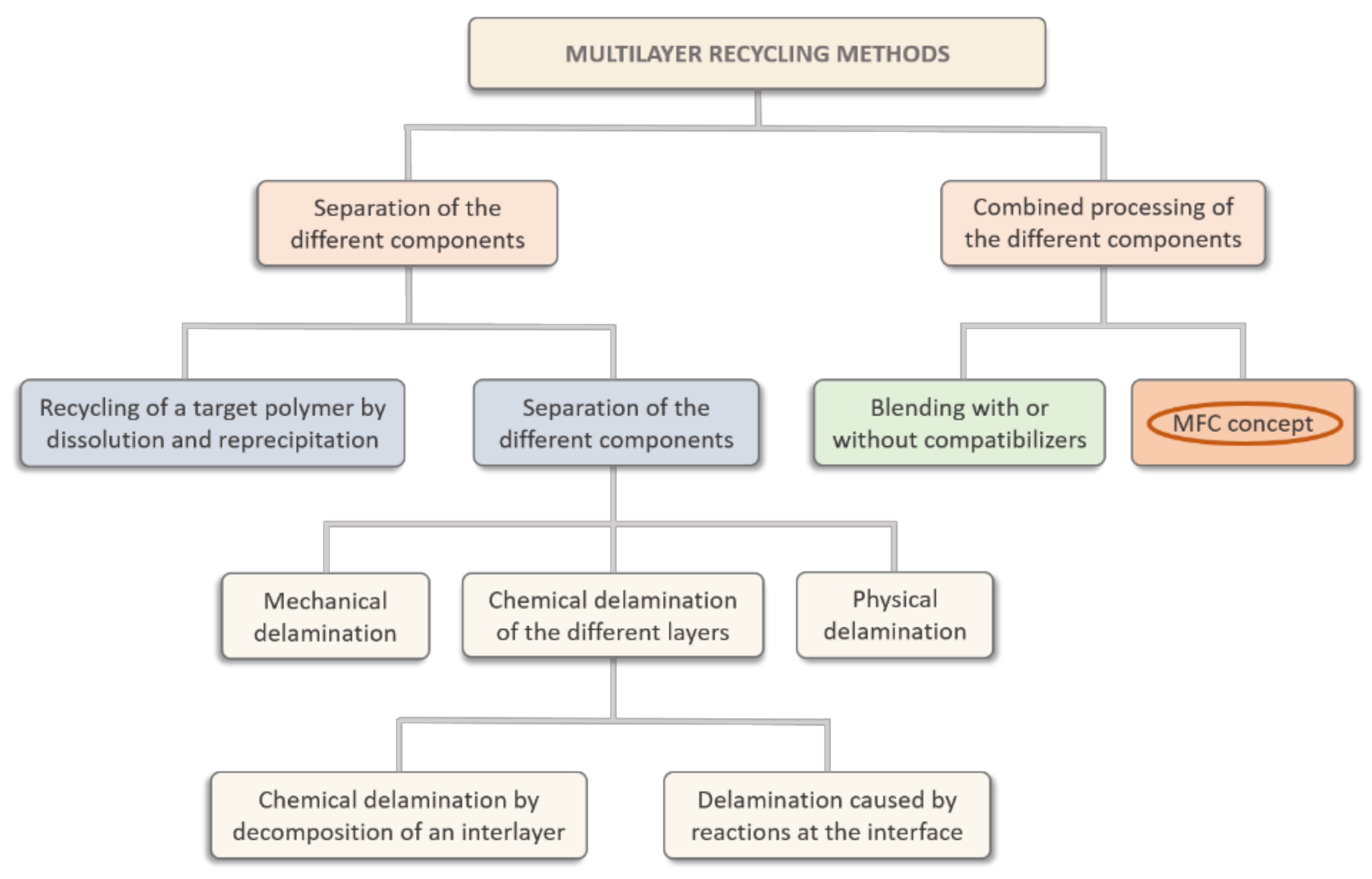
With multilayer films, adhesive layers can often be present between the different polymer layers [36]. At this moment, no industrial solution is available for a highly efficient separation of these multilayers [31]. This results in complex compositions, posing a huge challenge for the recyclability of the films. Regardless of the issues, researchers look towards new methods to recycle food packaging waste. Several methods are described in the literature, such as delamination processes, the separation of the different components by dissolution–reprecipitation, or combined processing with additives (without separation of the multilayer components) (Figure 2) [31].
Under the combined processing option is considered the re-processing of the mixture without separation of the components, either with or without the compatibilizer. Besides this blending, drawing of the MFC from the immiscible multilayer blend could be added to this section of combined processing, as immiscibility is one of the most important requirements for the MFC concept. Although the presence of the adhesives between the polymer layers might affect the re-processing, as well as the presence of inks or other contaminants, the successful production of MFCs out of multilayer packaging residues could be one step forward within the recycling field.
Next, MPO is a major component of the polymeric waste fraction since the polyolefins typically float in a float–sink installation and, as such, are frequently re-processed as a recycled blend into new products (e.g., garden furniture enclosures, livestock stable panels or decking for terraces) [37,38]. However, since MPO consists of PPs and PEs, which are considered to be compatible but only partially miscible [39], their blends tend to separate at the interface. Therefore, these blends may achieve limited mechanical properties, such as a reduced ductility, due to the immiscibility of the components [36,40,41]. Attempts to improve the properties of MPOs have proven challenging so far [40,41,42]. Reinforcing the MPO matrix by PET microfibres could yield recycled composites with improved stiffness, without sacrificing too much of their ductility.
The final matrix selection falls within the production of electrical and electronic equipment (EEE), which is one of the fastest-growing global manufacturing activities, even exceeding those of car manufacturing; this large quantity of products is accompanied by substantial growth in the waste [43,44,45,46]. Waste from electrical and electronic equipment (WEEE) mainly consists of ferrous and non-ferrous metals, glass and plastics. The average plastic content is about 30%, the major components of which are acrylonitrile butadiene styrene (ABS—30%) and high-impact polystyrene (HIPS—25%), followed by polycarbonate (PC—10%), PC/ABS blend (9%) and PP (8%) [44,47]. Even though all these polymers can be separated into mono-streams and recycled into new products [44], questions remain about the level of purity of these streams. Several challenges, such as variability in the material composition and the presence of organic and inorganic fillers [45], present themselves, as well as the degradation which might occur during the product’s lifetime [44]. Therefore, the loss of quality will be inevitable.
PP filled with talc is one of the composites frequently found in WEEE and end-of-life vehicles (ELVs). However, it has been observed that the re-processing of the recycled PP filled with talc cannot achieve the very high level of stiffness of 4000 MPa which is possible with virgin PP. Researchers have found that this issue might be a result of contamination from PE and copolymer PP [46].
Although PP cannot be separated from talc, this material must be re-processed as such. It is known that mineral fillers together with reinforcing fibres may increase mechanical properties such as modulus [48,49,50]. However, some research studies have also shown negative effects on impact and tensile strength [51]. Although these studies have been conducted with commercial fibres, it is worth trying to apply the MFC concept to reinforce such a matrix with PET microfibres and study the effect of the presence of talc in the MFCs.
3. Experimental Methods
3.1. Materials
The selected matrices for the MFC preparation were a recycled bilayer PP/PET film, a recycled MPO and a recycled PP filled with talc. In Table 1, materials and their abbreviations are listed.
The first recycled material used in this study was a PP/PET commercial bilayer film with a weight ratio of 80/20 supplied by Packas (Merelbeke, Belgium), a trading company specialising in multilayer barrier films for food packaging. The weight ratio of the film is determined from the thicknesses of the individual layers, 50 µm PP and 12 µm PET. The film was shredded and dried for 15 h at 80 °C and 2 h at 120 °C before processing. Due to its non-homogenous nature and low bulk density, this mixture needed an additional compounding step via a conical twin-screw extruder (MAS24). Therefore, the recycled PP/PET film was re-processed into a blend (RFPP/PET blend, RF—abbrev. recycled film) at a set of temperatures of 160–200–220–230 °C. The screw speed was set at 70 rpm. To avoid the degradation of the PET, only the PP component was re-melted. The extrudate was obtained as a filament and subsequently granulated into pellets for further MFC processing.
The second recycled matrix, MPO (RMPO), was prepared by dry-mixing two types of recycled materials PP pellets (Dipolen PP with melt flow rate (MFR) 5 g/10 min, 230 °C/2.16 kg) and wt% 50/50 PP/PE pellets (Dipolen S with MFR 10 g/10 min, 230 °C/2.16 kg), both of which were kindly donated by Borealis (Vienna, Austria), to obtain a weight ratio of 80/20 PP/PE in the MPO matrix.
The third matrix, PP filled with 20 wt% talc (RPPtalc) (MFR 7.5–10 g/10 min, 240 °C/5.0 kg), was used as received from the supplier (MBA Polymers, NJ, USA). As reinforcement, virgin PET (LIGHTER C93), a bottle-grade material with an intrinsic viscosity of 0.80 ± 0.02 dL/g from Equipolymers (Schkopau, Germany) was used. Before processing, PET was dried in a vacuum oven for 15 h at 120 °C (datasheets of polymers are available in Supplementary Data). Besides the recycled materials and virgin PET pellets, the compatibilizer ethylene-propylene elastomer grafted maleic anhydride (POE-g-MA), (Acti-Tech 16MA13) was used in this study too. It was kindly donated by the Nordic Grafting Company (NGC, Hellerup, Denmark). PET and the shredded RFPP/PET blend were dried as usual before processing, while RPPtalc was dried for 2 h at 60 °C.
3.2. Preparation of Recycled MFCs
The preparation of the samples consisted of the preparation of an injection moulding blend (IMB) by two-step processing (extrusion—injection moulding) and microfibrillar composites (MFCs) by three-step processing (extrusion—cold drawing—injection moulding). The preparation of the recycled blends with and without compatibilizer was conducted via a twin-screw extruder (Coperion ZSK18, Stuttgart, Germany) with two co-rotating screws of 18 mm in diameter, L/D = 40 and a die opening of 19 mm × 2 mm. The barrel temperatures were set at 205–245–250–250–255–255–245–245–245 °C. The extrudate was obtained as a sheet with dimensions of 30 mm × 1.3 mm.
To obtain the microfibrillar structure, the cooled extrudate was entered directly into a hot oven (200 °C, 55.5 cm × 60 cm) and cold drawn by a pair of rollers above the glass transition temperature (Tg) of PET. During drawing, the surface temperature of the extrudate was measured and amounted to approximately 95 °C, and drawn at draw ratio 8. Afterwards, the blends were shredded and dried before the isotropization step. The shredded sheets were injection moulded by Engel 80T (Schwertberg, Austria) at 180–190–200–210 °C in a standard ASTM mould with a temperature of 30 °C, obtaining both tensile (114 × 6.45 × 4 mm3, with a gauge length of 33 mm) and impact specimens (126 × 13 × 3 mm3). In Table 2, the abbreviations and compositions of the samples are listed.
3.3. Characterisation of Recycled MFCs
The melt flow rate (MFR) of the MAS-extruded RFPP/PET blend was measured by a Davenport MFI 10 device (Ametec, Berwyn, PA, USA) according to ISO1133 at a temperature of 230 °C and a load of 2.16 kg. For comparison, virgin PP and PET were measured at 230 °C and 280 °C, respectively (Table 3).
All samples were characterised after the third processing step (injection moulding). To study the morphology of the samples, scanning electron microscopy (SEM) with a FEG SEM JEOL JSM-7600F 202 (Tokyo, Japan) was used. The samples were immersed in liquid nitrogen and subsequently fractured. For the observation of the fibre microstructure, the PP matrix together with POE was selectively dissolved in hot xylene for several hours. Furthermore, the sample surfaces were sputtered with gold by a Bal-Tec SCD005 sputter coater (Bal-Tec, Balzers, Liechtenstein). Micrographs were obtained with an accelerating voltage of 20 kV. The average diameter of the particles or fibres was measured with ImageJ software. For the calculation, at least 50 measurements were used.
Differential scanning calorimetry (DSC) was employed to investigate the crystallisation and melting behaviour. Measurements were performed in two cycles of heating–cooling under a nitrogen atmosphere in a temperature range between 30 and 200 °C by a Netzsch DSC 214 Polyma device (Selb, Germany). The heating/cooling rate was 10 °C/min, and the flow of nitrogen gas was 20 mL/min. χc was calculated for the PP component based on the theoretical enthalpy for 100% crystalline polymer and taking the mass percentage into account (Equation (1)) [52].
where ΔH° for PP is 207 J/g [32], and wf is the weight fraction of the relevant polymer in the PP/PET composition. The mean thermal properties were averaged from three measurements and the differences were calculated by comparing population means by an independent t-test via the software package SPSS Statistics 24 (Armonk, NY, USA).
Mechanical characterisation was conducted under controlled conditions (23 °C and 50% relative humidity), after the samples had been conditioned for a minimum of 48 h within this controlled environment. The standard tensile bars were tested with an Instron 5565 tensile device (Nordwood, MA, USA) according to standard ISO 527. During the tests, different test speeds were used before and after the Instron dynamic extensometer was removed (type catalogue 2620-603 with a gauge length of 12.5 mm), 1 mm/min and 5 mm/min, respectively. Analysis was performed with Bluehill software. The notched Charpy impact test was used to evaluate the toughness of the samples by using a Tinius Olsen IT 503 Pendulum Impact Tester (Ulm, Germany) according to the ISO 179 standard. The specimens were notched in the middle of the sample to a depth of 2 mm, placed horizontally with the notch oriented away from the pendulum and broken by a hammer with an energy of 2 J. At least 10 specimens were tested for both tensile and impact tests. The differences between the samples were calculated by an independent t-test preceded by a Levene’s test for equality of variance via the software package SPSS Statistics 24 (Armonk, NY, USA) with a probability value of 0.05.
4. Microstructural Study
4.1. Morphology Development of RFIMBs and RFMFCs
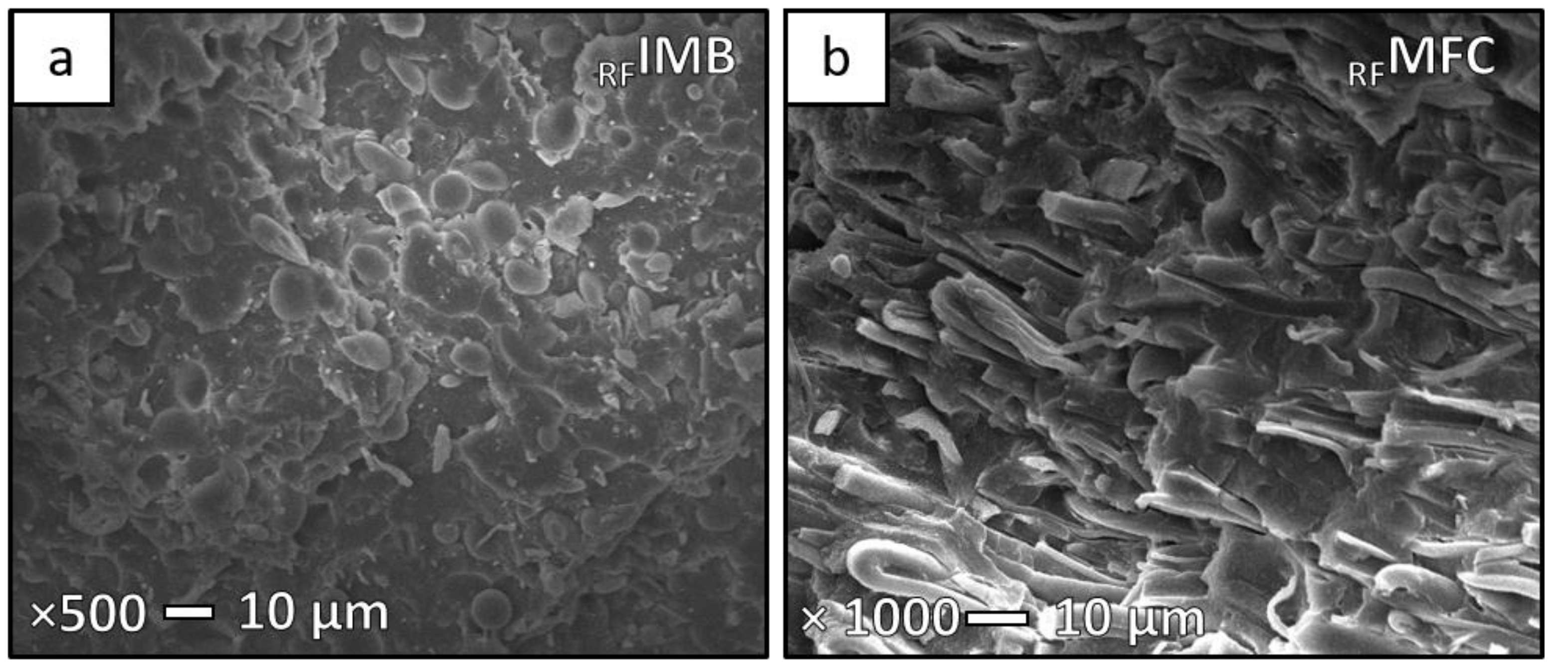
The morphology of the recycled samples was studied by SEM. Figure 3 shows micrographs of the microstructures obtained for RFIMB and RFMFC prepared from the MAS-extruded RFPP/PET blend. From the micrograph 3a, coalesced PET particles with a quite large average diameter (8.4 µm, Table 4) can be observed, as well as their poor distribution within the matrix. The reason for these characteristics might lie in the high MFR (43 g/10 min, 280 °C) of the RFPP/PET blend. During the processing of the RFPP/PET blend via twin-screw extrusion, a low viscosity molten material was observed at the exit of the die. The low viscosity is probably a result of smaller molecular weight, which is an indicator of the chain scission [30,53,54,55].
It is known that the apparent viscosity of a pseudoplastic blend is dependent on the shear rate: the greater the shear rate, the lower the viscosity. Achieving an optimal viscosity is of huge importance for the further drawing of the blends.
Micrograph 3b shows the RFMFC microstructure, presenting relatively uniform PET fibres with an average diameter of 3.0 µm. This diameter is relatively large when compared to the average diameters reported in our previous study conducted on the virgin MFC containing the same composition ratio (0.6 µm) [27]. Due to the low viscosity of the RFPP/PET blend, the formation of larger particle sizes occurred, and consequently resulted in larger fibre diameters.
In a recent study by Yi et al. [56], the influence of viscosity ratio (λ) in PP/PET MFCs was reported. They explain that a finer microfibrillar morphology is more likely to form in a matrix with lower MFR. Although the λ is not known for RFMFC, conclusions can be drawn only according to the MFR value. Thus, it could be assumed that the higher MFR of this recycled blend contributes to the wider particle size distribution and favours the coarser fibrillar morphology.
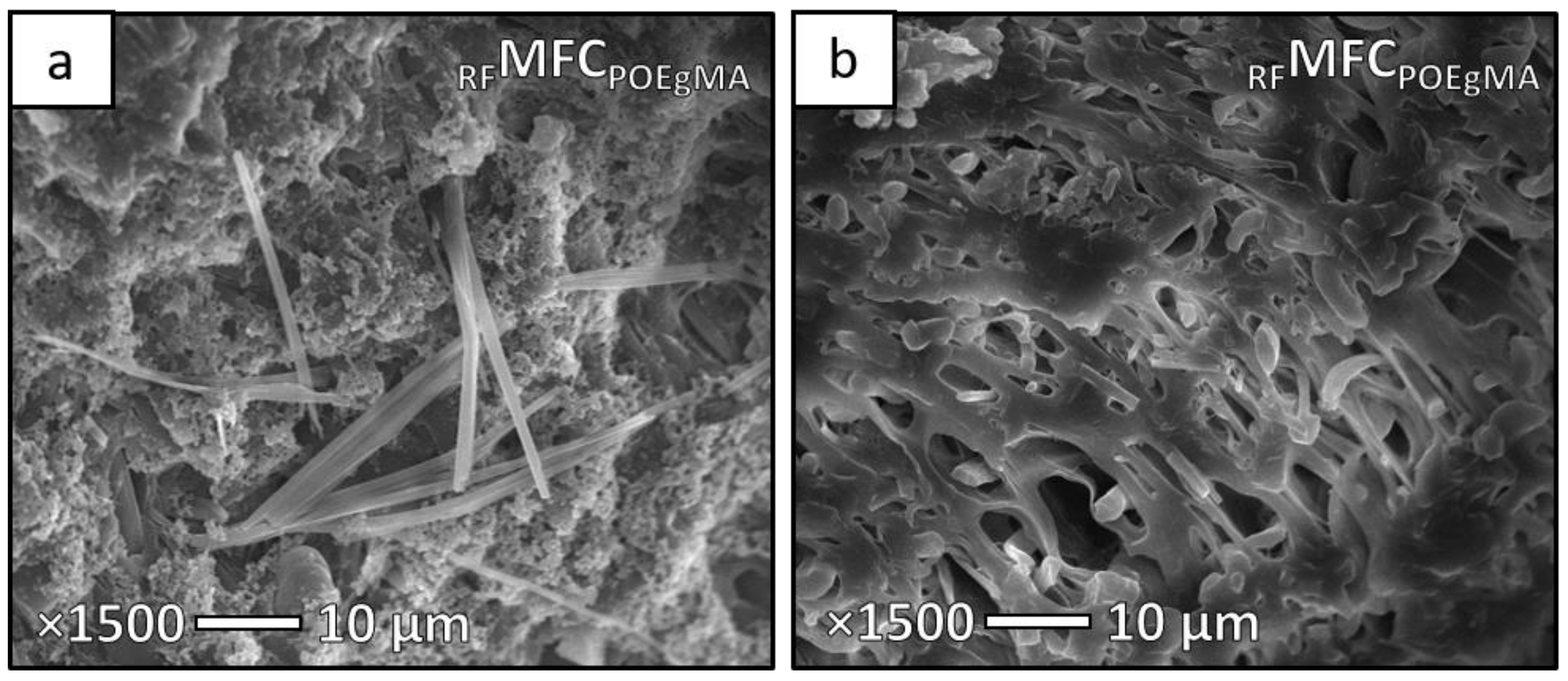
Furthermore, in the case of RFMFCPOEgMA, the average fibre diameter drastically decreased to 0.9 µm, and it seems that fibres with high aspect ratio are present (Figure 4a), which is unusual for compatibilized MFC samples, as reported in our recent study [27]. However, the presence of large cavities can be noted in Figure 4b around the fibres, which could be either an indication of lower adhesion along the sample or a dissolved PP matrix.
4.2. Morphology Development of RMPOIMBs and RMPOMFCs
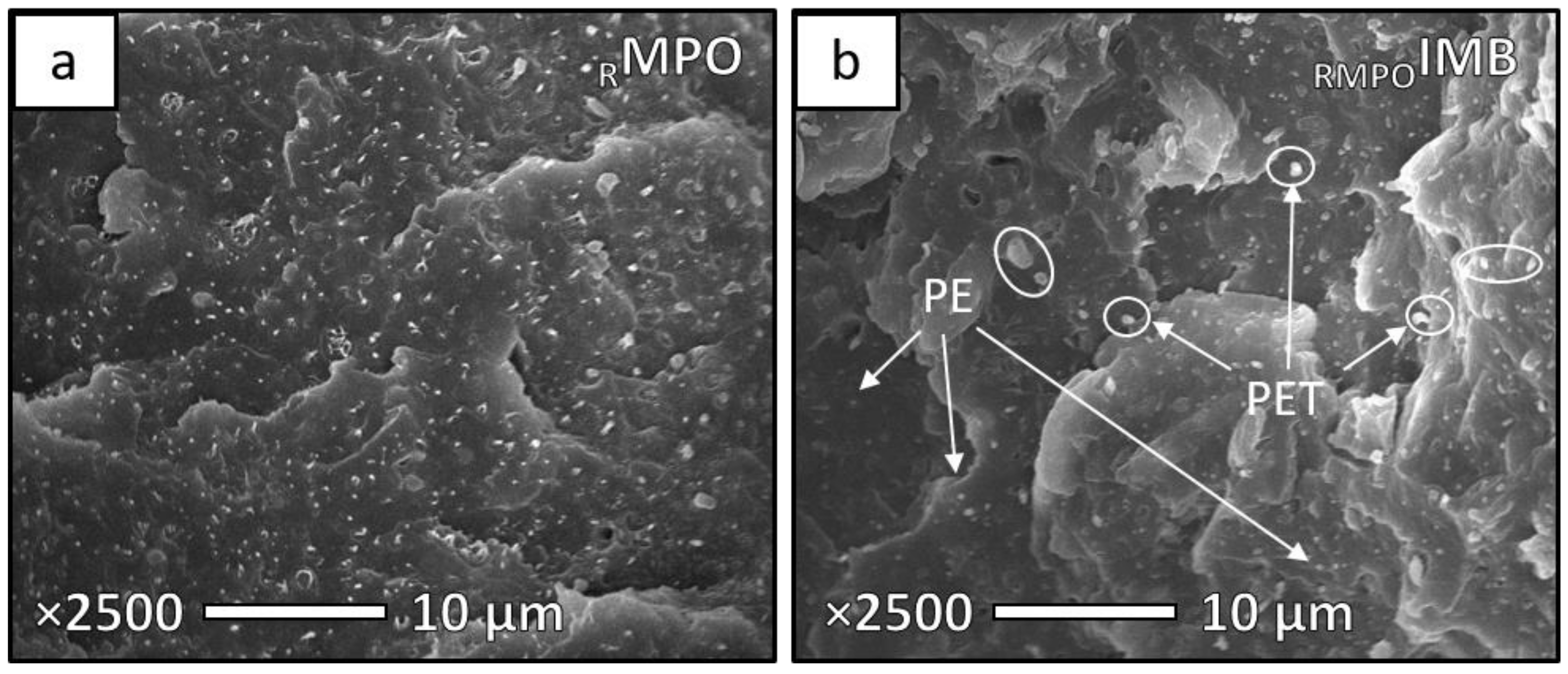
A second series of recycled samples was prepared using RMPO as a matrix. Figure 5 shows the morphologies of recycled RMPO and RMPOIMB. RMPO shows the uniform dispersion and distribution of RPE particles in the RPP matrix (micrograph 5a).
RMPO is considered as a binary blend composed of the PE and the PP (DSC analysis confirmed, thermograms available in Supplementary Data, Figure S3), although it is difficult to detect if only one type of RPE is present in RPP. In Figure 5b, the morphology of RMPOIMB can be observed. Both RPE and PET particles are present, with average diameters of 0.4 µm and 1.8 µm, respectively.
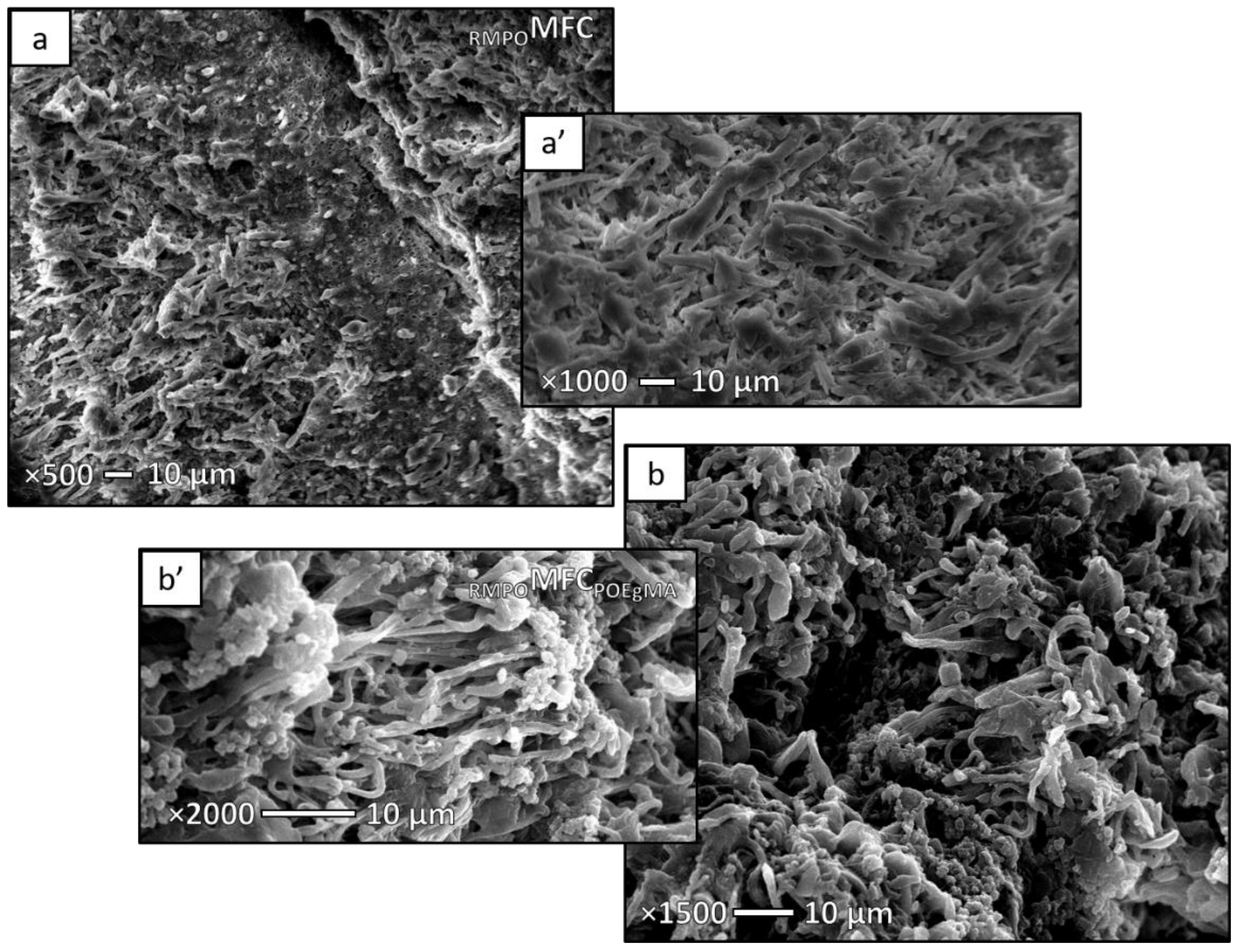
Chemically etched samples of RMPOMFC and RMPOMFCPOEgMA are represented in Figure 6. RMPOMFC shows well-distributed PET fibres within an RMPO matrix with an average diameter of 1.5 µm, while in the RMPOMFCPOEgMA sample, the diameter has halved to 0.8 µm. In this sample, it seems that high aspect ratio fibres are present (Figure 6b′). As the RMPO has a higher viscosity than the PET component, it is assumed that a higher degree of deformation of PET is present, increasing the level of coalescence during drawing and resulting in higher aspect ratio fibres in both RMPOMFC and RMPOMFCPOEgMA [57]. Similar results have been found in other studies [56,58]. Both Yi et al. [56] and Zhao et al. [58] reported that a finer fibrillar morphology may be achieved in matrices with low MFR.
4.3. Morphology Development of RPPtalcIMBs and RPPtalcMFCs
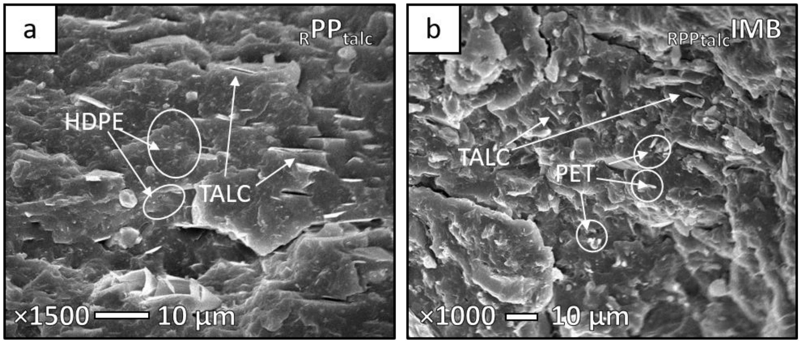
The morphology of IMBs and MFCs prepared with the talc-filled PP are shown in Figure 7 and Figure 8. From the micrograph presented in Figure 7a, dispersed talc plates can be seen. However, besides the talc, a certain amount of HDPE particles with average diameters of 0.4 µm are present in the matrix.
According to the datasheet provided by the supplier, it is considered that this PP contains a maximum of 10 wt% of HDPE, thus it is obvious to detect it under the microscope as a minor dispersed component.
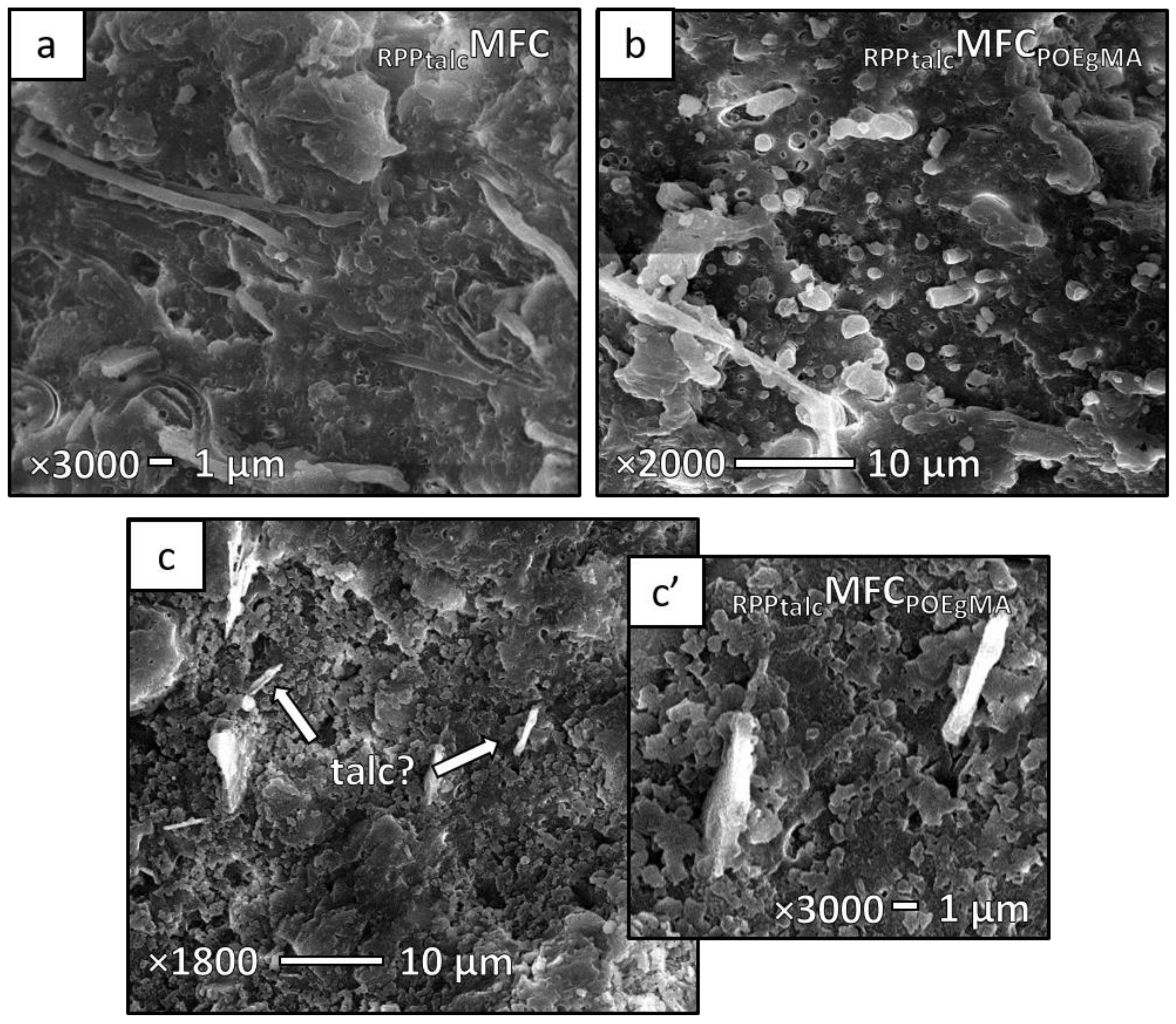
In RPPtalcIMB, the average diameter of the PET particles was found to be 2 µm. During the extraction of PP from these samples, a slower diffusion of xylene into the PP component than for other MFC samples was noticed, which resulted in partially dissolved PP (Figure 8c,c′), even after several hours of extraction. Probably, the presence of talc plates made the diffusion more difficult, as the talc starts to decompose and lose its hydroxyl groups above 900 °C [59], while the boiling point of m-xylene is 139 °C. Thus, at this temperature, it would be difficult to affect the structure of talc.
Even though the matrix was not completely removed, the PET microfibrillar structure is present in both RPPtalcMFC and RPPtalcMFCPOEgMA, showing long and thin fibres (Figure 8a,b). The average diameter was found to be 0.7 µm and 1.0 µm for RPPtalcMFC and RPPtalcMFCPOEgMA, respectively.
As shown above, it is possible to create fibrillar PET structures within the recycled matrices. However, it is believed that the main factor in forming a uniform and fine fibrillar morphology is the viscosity ratio of the matrix and the reinforcement. Overall, understanding how the viscosity ratio influences the fibre formation is of crucial importance for achieving an optimal morphology [60,61,62].
5. Thermal Properties
5.1. Crystallisation Behaviour of RFIMBs and RFMFCs
It has already been shown in numerous previous studies [22,23,28,42,52,56,58,63] that the crystallisation behaviour of virgin matrices can be affected by the PET component; hence, similar behaviour was expected to happen within the IMBs and MFCs from recycled materials. In Table 5, the thermal properties of the composites prepared from the recycled film are listed (DSC graphs are available in Supplementary Data).
It can be seen that there is no significant difference in the melting temperature (Tm) of the samples, while crystallinity (χc) increased in RFMFC and RFMFCPOEgMA when compared to RFIMB. This latter finding was to be expected, as the PET fibres have a significant nucleating effect on the PP matrix, particularly in RFMFCPOEgMA, due to the presence of POE-g-MA compatibilizer [27]. In this sample, it is most likely that POE-g-MA isolated particles have an additional nucleating effect which has contributed to the increased crystallinity. Moreover, the crystallisation temperature (Tc) in RFMFCPOEgMA shifted back to the level of RFIMB (see onset and endset Tc in Supplementary Data, Figure S2). Due to the presence of the compatibilizer, the coalescence of PET particles was constrained, leading to shorter PET fibres. Thus, the onset crystallisation is not affected in the same way as by long PET fibres [27].
5.2. Crystallisation Behaviour of RMPOIMBs and RMPOMFCs
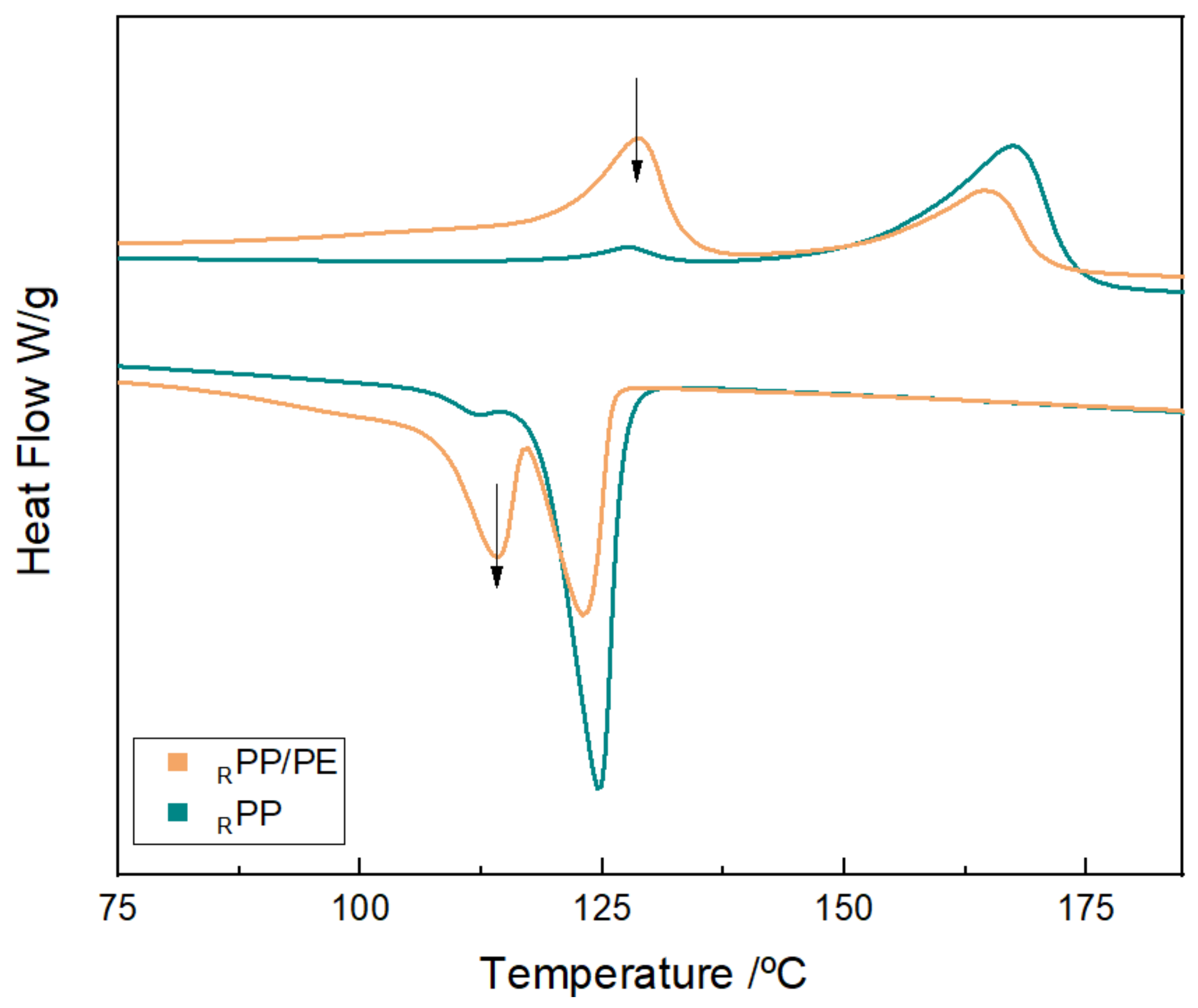
Pellets used for the RMPO blend were analysed as references for the RMPOIMBs and RMPOMFCs. From the graph shown in Figure 9, it can be noticed that Tc of RPP and RPP/PE was found at 124 and 123 °C, respectively.
A higher Tc for RPP/PE was expected, as it consists of 50 wt% PE and 50 wt% PP. However, RPP showed its Tc at the same level, which is unusual for PP if compared to the virgin material. It is known that PP architecture may be affected by chain scission, which can affect crystallisation behaviour, contributing to a higher Tc of PP. After multiple processing steps, it is expected that PP crystallises faster due to shorter chains [30]. By analysing the DSC curve, a low melting peak indicating the presence of the PE component was detected. Thus, the enhanced crystallisation of RPP may come from a certain amount of RPE too, which could influence both RPP and RPP/PE crystallisation temperatures.
Furthermore, the thermal properties of the recycled MPO materials are listed in Table 6.
For the RPP component, χc, Tm and Tc are listed, while for the PE component, the heat of fusion (ΔHmPE) is presented because the χc was not calculated as the exact percentage of RPE was not known; it may be assumed that between 10 and 15 wt% of RPE was present in the composites. However, it can be noticed that ΔHmPE decreases in blends and MFCs, which is an indication of a lower crystallinity (DSC curves may be found in Supplementary Data, Figures S3–S6).
Statistically, there are no significant differences between the crystallinities of the samples. The reason might lie in the presence of the RPE component, which could already act as a nucleating agent for RPP [64,65]. However, it may be noticed that Tm in RMPOIMB and both RMPOMFCs increased, while the Tc peak was found to be lower compared to the values reported for RMPO blend. This might be an indication of a reduction in RPP crystallite perfection [64].
It can also be detected that the presence of POE-g-MA did not affect Tc of PP in RMPOMFCPOEgMA like it did in RFMFCPOEgMA. The reason for such behaviour can be supported by the morphological study. From the microscopic observations (Figure 6b,b′), fibres with a high aspect ratio were detected, and as already known, they are strong nucleators for the matrix.
5.3. Crystallisation Behaviour of RPPtalcIMBs and RPPtalcMFCs
Table 7 shows the thermal properties of the PPtalc-based blends and MFCs. Crystallinity did not change among the samples, nor Tm, meaning that the addition of PET does not influence the thermal properties of RPPtalc. If compared to the values for virgin PP reported in previous studies [23,27], it can be noticed that the Tc of the PPtalc is already high (Tc = 126 °C), meaning that it was probably previously nucleated by the presence of talc and small amounts of PE (DSC thermograms available in Supplementary Data, Figures S7).
Talc and other inorganic fillers are considered to be strong nucleators for the crystallisation of PP. By inducing the nucleation of PP, a transcrystalline structure normal to the filler surface is formed at the interface and high heterogeneous nucleation occurs at the surface filler/matrix [66,67,68,69,70]. Good options for studying transcrystallinity are transmission electron microscopy (TEM) or wide-angle x-ray diffraction (WAXD) analyses, which could give insights into the lamellae orientation.
Furthermore, it is interesting to observe the crystallisation behaviour in RPPtalcIMB and RPPtalcMFCs. A similar effect to that in RMPOIMB and RMPOMFCs was noticed—the addition of the PET component to the already talc-filled PP matrix postponed the crystallisation. The delayed crystallisation might be a reason for the less perfect PP crystals present due to two reinforcements that competitively act as nucleating agents. Despite the addition of POE-g-MA into RPPtalcMFC, Tc slightly decreased. Thus, there are two reasons: one is the strong nucleating effect of the talc, which blocks the usually noticeable effect of the POE-g-MA in compatibilized MFCs [27]; the other is long microfibres which contribute to the heterogeneous nucleation of the matrix.
In general, we could notice that the crystallisation behaviour is quite complex for these multi-material systems.
6. Mechanical Behaviour
6.1. Mechanical Properties of RFIMB and RFMFCs
Mechanical behaviour plays a crucial role in defining the final application of recycled materials. The main goal is to achieve higher toughness and stiffness of these MFCs by introducing PET fibres.
The mechanical properties of RFIMB and RFMFCs are listed in Table 8. As can be seen, there is no significant difference between the values obtained for the impact strength, even though the values reported are already high for the recycled blends if compared to those reported for the virgin blends and MFCs in our previous studies [23,27]. However, the PP and PET grades used in these studies differ.
Nevertheless, the literature [24,52,63,71,72,73,74,75,76] based on virgin MFCs shows that, in most cases, the microfibres will affect the crystallinity and spherulite size of the matrix, contributing to a higher toughness. Hence, the same trend was expected to occur within the recycled MFCs, as an increment in crystallinities of both RFMFC and RFMFCPOEgMA was detected. The size of PP spherulites was not measured in the recycled samples. However, we have assumed that there is a decrease in these sizes due to the presence of PET and POE-g-MA [27]. Despite an achieved increase in crystallinity and relatively uniform fibre morphology, we see no particular improvement in RFMFC impact properties. Perhaps the reason lies in the long fibres found for RFMFC. In one of our studies [27], it was reported that short fibres are more effective in transmitting the stress to the matrix than long ones. Besides the impact strength, no improvement in tensile modulus was detected either; the tensile strength, however, significantly increased. This increase in tensile strength can be an indication that some interfacial contact still exists at the fibre–matrix interface due to the large surface area of the PET fibres [75]. Additionally, strain at yield for this sample surprisingly achieved the highest value, which means that cavitation was constrained and both polymer constituents could strain together.
Furthermore, the tensile modulus of RFMFCPOEgMA significantly decreased when compared to RFIMB and RFMFC. However, this decrease was expected due to the presence of the elastomeric backbone of the POE-g-MA [27,30,77]. It is interesting that for the yield strength of RFMFCPOEgMA, an increment of 20% was detected when compared to RFIMB. In spite of its slightly lower yield strength when compared to RFMFC, it can be assumed that the adhesion has been improved slightly due to the presence of the compatibilizer; on the other hand, a reduction in yield strain and strain at break would indicate the opposite. Therefore, the question arises—as toughness did not increase significantly, how effective was POE-g-MA in this mixture?
From the micrograph in Figure 4b, some large cavities can be noticed, which is not common for compatibilized MFC. The addition of POE-g-MA was expected to improve the adhesion between PP and PET. However, it is known that several mechanisms may occur during stretching—like decohesion at the interface PP–PET and PP–compatibilizer, or cavitation of the isolated POE-g-MA particles, which were probably pronounced, and the specimens could no longer withstand the applied stress and failure took place earlier [27,78].
6.2. Mechanical Properties of RMPOIMB and RMPOMFCs
RMPO samples show behaviour similar to samples made from the recycled film (Table 9). Although RMPO is already a recycled blend, quite a high impact strength was noted for this sample. On the one hand, this is not a surprising result for RMPOs, as PE is often added to PP to increase its toughness [36,64,65,79], so the same effect will be present in the recycled mixtures too. On the other hand, it is disappointing to notice the decrease in impact strength for the RMPOIMB and RMPOMFC. This decrease might be explained by the complicated three-component morphology and immiscibility of the components present in this sample.
It was shown by the SEM image of RMPOMFC (Figure 6) that a relatively good dispersion of the PET fibres is present, thus it is not expected to fail in the same way as RMPOIMB. In the RMPOMFC, both RPE particles and PET fibres should dissipate energy more actively to the matrix. However, a reduction in crystallinity was shown for both RMPOIMB and RMPOMFC. This could be linked to the reduction in impact strength, as the toughness would increase with an increase in χc [80].
Contrary to RMPOIMB and RMPOMFC, the impact strength of RMPOMFCPOEgMA shows an increase of 11% in comparison to RMPO, which is not significant if we consider that both PET and POE-g-MA were added to the recycled matrix. Although a toughening effect in RMPOMFCPOEgMA was detected, no increment was noticed in tensile strength or modulus. Even a reduction in strain at break can be seen when compared with RMPO, and this could mean that the concentration of POE-g-MA was either too low for this composition of recycled polymers or interacted with the small amount of RPE present in the mixture too. POE backbone is a copolymer of propylene–ethylene, and there is a strong possibility that this interaction took place due to miscibility with the RPE. The elastomer-based compatibilizers would probably show a slight preference for PE over PP [81,82]. Therefore, POE-g-MA could interact with both PP and PE, lowering interfacial tensions between them, as well as between PP and PET, and PE and PET, making the amount of POE-g-MA insufficient for the prime interaction between PP and PET.
For the samples RMPOIMB and RMPOMFC, the tensile properties also remained intact, and only a small and insignificant increase in tensile modulus can be noted. Altogether, it can be concluded that the addition of PET and the application of the MFC concept did not contribute to an increase in the MPO mechanical properties, because of the multi-component morphology, low interfacial contact between fibres and matrix or insufficient concentration of the compatibilizer.
6.3. Mechanical Properties of RPPtalcIMB and RPPtalcMFCs
The last set of samples are composites made with RPPtalc as the matrix (Table 10). RPPtalcIMB and RPPtalcMFC show the same behaviour as RMPOIMB and RMPOMFC, namely, an increase in impact strength, while tensile properties remained unaffected. RPPtalcMFCPOEgMA gained a little improvement in impact strength, but the rest of its properties are unchanged. Unfortunately, drawing MFCs from RPPtalc and PET does not contribute to improved properties.
To obtain significant improvements, the composition ratios could be adapted, increasing the percentage of the compatibilizer or even changing the type of compatibilizer; but still, the question is—what would be the added value of increasing concentrations of expensive additives? In this case, the manufacturers would probably add more talc to reach the desired properties for the final application.
In general, both the type of reinforcements and their aspect ratio are of huge importance. In this composite, both rigid (talc) and flexible (PET fibres) reinforcements were present. Obviously, due to differences in their individual behaviours, they might compete during sample deformation which could contribute to a reduction of the properties of the MFCs. Hence, the addition of different types of polymeric fibres might have a higher probability of success.
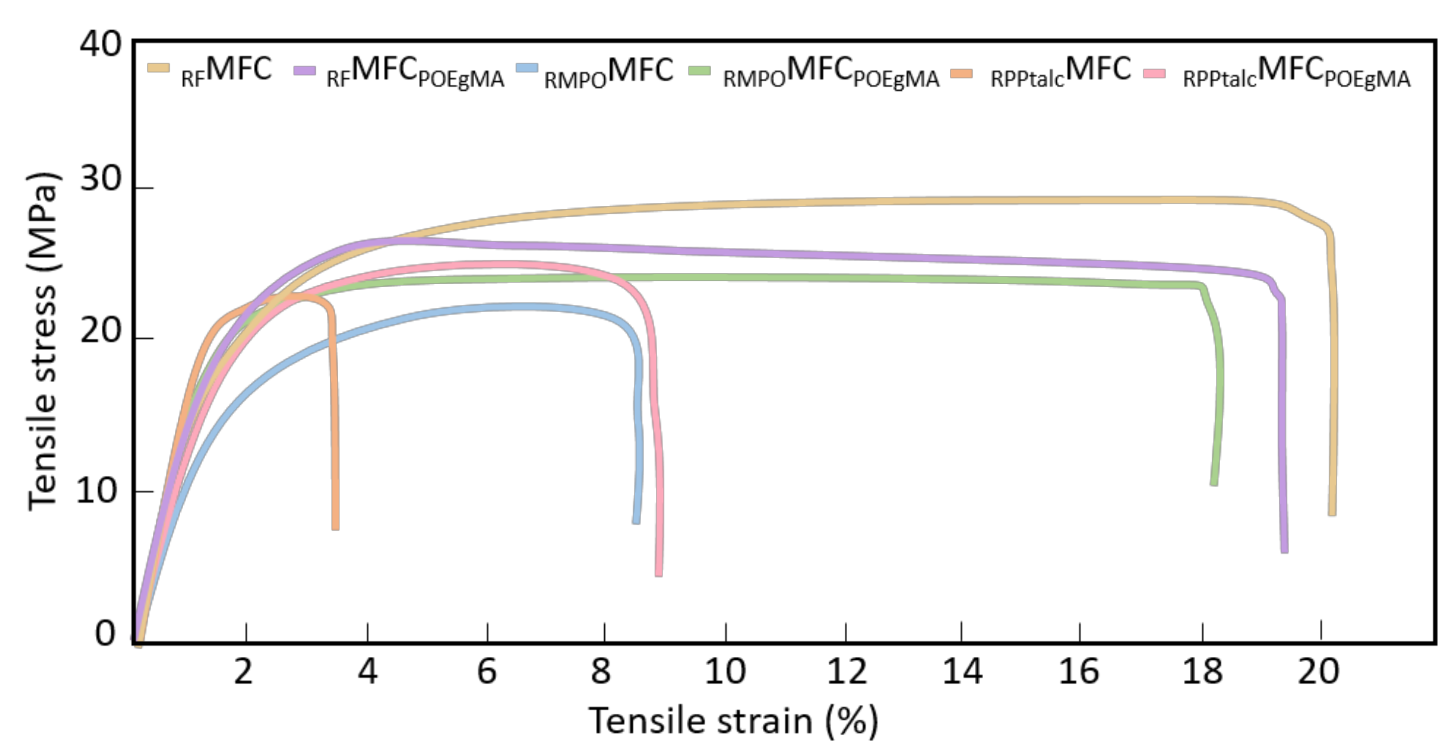
Figure 10 summarises the tensile behaviour of the recycled MFCs. It can be noticed that the most optimal stress–strain behaviour was achieved for the samples RFMFC and RFMFCPOEgMA in terms of high strength and strain at break. RMPOMFCPOEgMA kept the same level for strain at break, while achieved strength was lower, and RMPOMFC, RPPtalcMFCPOEgMA and RPPtalcMFC achieved the lowest values.
7. Conclusions
This manuscript presented the MFC concept as a possible solution for the upcycling of recycled materials. The aim of this study was to improve the properties of recycled matrices by incorporating PET microfibres as reinforcement. For this, three different matrices were studied: bilayer PP/PET film, MPO and talc-filled PP.
SEM microscopy confirmed a high level of coalescence present in RFIMB, due to the low viscosity of the recycled blend. In RFMFC, uniform dispersion and distribution of the microfibres were confirmed, but with larger fibre diameters, while the average fibre diameter decreased in the compatibilized RFMFC. Furthermore, the presence of the RPE component in RMPO-based IMBs and MFCs was shown, which confirmed the heterogeneity of these composites. A microfibrillar morphology was present in all MFC samples. However, it was shown that drawing of the dispersed component strongly depends on the type of matrix and its MFR. Hence, it can be concluded that the viscosity ratio of the blend is the key factor in forming uniform and fine fibrillar morphology.
Crystallisation behaviour was studied by DSC, and it has been shown that its interpretation in multi-material systems is a complex matter. It was demonstrated that PET fibres do not have any influence on melting behaviour and crystallinity in composites based on RMPO and RPPtalc, probably due to the presence of the RPE component, which already acted as a nucleating agent for RPP. In the case of RFMFCPOEgMA, a significant increase in crystallinity was detected due to the heterogeneous nucleation of both PET fibres and isolated compatibilizer particles, which agrees with previous studies reported on virgin MFCs. Furthermore, the talc present in PP has a stronger nucleating effect than the high aspect ratio PET fibres. Unfortunately, the mechanical results were quite disappointing; almost no or little improvement was achieved in recycled IMBs and MFCs. The MFC concept was used for mixed polymer waste with the intention of improving the original properties of the recycled materials. However, it has been shown that the MFC structure does not contribute significantly to the recycled materials investigated here. According to the presented results, it can be concluded that PET fibres, as reinforcement, in combination with these recycled materials, do not show effectiveness, especially with RMPO and RPPtalc used as matrices. This failure to achieve high mechanical properties might be a consequence of several issues:
- possible thermal degradation of the polymeric components;
- suboptimal viscosity ratios, which affect the mixing and drawing of fibres;
- unsuitable composition ratios;
- insufficient addition of the compatibilizer;
- the presence of other small % contaminations in the recycled plastics, such as remnants of adhesive layers or mis-sorted non-target plastics;
- the combination of flexible PET fibres with rigid reinforcement talc.
Moreover, the formation of transcrystallinity layers may be affected, and the stress transfer between the reinforcement and the matrix may be reduced in such multi-component blends, resulting in a recycled MFC with poor properties. However, with the judicious selection of recycled grades, which take account of their origin and application and physical and rheological properties, it is possible that MFCs with optimal microstructure and properties might be achieved.
Further research within the upcycling of mixed plastic waste using the MFC concept could focus on various factors such as the viscosity of the recycled materials and the presence of different additives. Thus, studying the rheology of the recycled blends and MFCs would be of crucial importance. The level of purity is very important when the recycled mixture is used as an input in the MFC production. Therefore, the different grades of recycled materials should be studied, as well as the level of degradation.
Besides these suggested research actions, cost–benefit analysis and life cycle assessment should be taken into account in the evaluation of the material, energy and environmental implications of the MFC process.
Eventually, it could be worth trying to investigate the effect of aging and the recyclability of the MFCs, and to evaluate their properties after re-processing [25], as this has not been widely studied. The purpose of such a study could be the replacement of existing polymer blends in the market with recyclable MFCs which might be re-processed without a large loss in properties.
Supplementary Materials
The following are available online at https://www.mdpi.com/2071-1050/13/2/689/s1, Figure S1: DSC thermograms of RFMFC. Figure S2: DSC thermograms of RFMFCPOEgMA, Figure S3: DSC thermograms of RMPO. Figure S4: DSC thermograms of RMPOIMB. Figure S5: DSC thermograms of RMPOMFC. Figure S6: DSC thermograms of RMPOMFCPOEgMA. Figure S7: DSC thermograms of RPPtalc pellet. Figure S8: DSC thermograms of RPPtalc. Figure S9: DSC thermograms of RPPtalcIMB. Figure S10: DCS thermograms of RPPtalcMFC. Figure S11: DSC thermograms of RPPtalcMFCPOEgMA.
Author Contributions
Conceptualisation and visualisation, M.K., L.D. and K.R.; investigation, data curation and formal analysis, M.K.; writing—original draft preparation, M.K.; writing—review and editing, M.K., L.D. and K.R.; supervision, K.R. and L.C. All authors have read and agreed to the published version of the manuscript.
Funding
This research was financially supported by Ghent University, Belgium.
Institutional Review Board Statement
Not applicable.
Informed Consent Statement
Not applicable.
Data Availability Statement
Data is contained within the article or supplementary material.
Acknowledgments
The authors gratefully acknowledge colleague Rudinei Fiorio for proofreading the English language.
Conflicts of Interest
The authors declare no conflict of interest. The funders had no role in the design of the study, in the collection, analyses, or interpretation of data, in the writing of the manuscript or in the decision to publish the results.
References
- Al-Salem, S.M.; Lettieri, P.; Baeyens, J. Recycling and recovery routes of plastic solid waste (PSW): A review. Waste Manag. 2009, 29, 2625–2643. [Google Scholar] [CrossRef]
- Evstatiev, M.; Fakirov, S.; Krasteva, B.; Friedrich, K.; Covas, J.A.; Cunha, A.M. Recycling of poly(ethylene terephthalate) as polymer-polymer composites. Polym. Eng. Sci. 2002, 42, 826–835. [Google Scholar] [CrossRef]
- Lei, Y.; Wu, Q.; Zhang, Q. Morphology and properties of microfibrillar composites based on recycled poly (ethylene terephthalate) and high density polyethylene. Compos. Part A Appl. Sci. Manuf. 2009, 40, 904–912. [Google Scholar] [CrossRef]
- Lei, Y.; Wu, Q.; Clemons, C.M.; Guo, W. Phase structure and properties of poly (ethylene terephthalate)/high-density polyethylene based on recycled materials. J. Appl. Polym. Sci. 2009, 113, 1710–1719. [Google Scholar] [CrossRef]
- Ragaert, K.; Hubo, S.; Delva, L.; Veelaert, L.; Du Bois, E. Upcycling of contaminated post-industrial polypropylene waste: A design from recycling case study. Polym. Eng. Sci. 2018, 58, 528–534. [Google Scholar] [CrossRef]
- Schiers, J. Polymer Recycling: Science, Technology and Applications; Wiley & Sons Ltd.: Chichester, UK, 1998. [Google Scholar]
- Ragaert, K.; Delva, L.; Van Geem, K. Mechanical and chemical recycling of solid plastic waste. Waste Manag. 2017, 69, 24–58. [Google Scholar] [CrossRef]
- Economics, M. The Circular Economy—A Powerful Force for Climate Mitigation; Material Economics Sverige AB: Stockholm, Sweden, 2018. [Google Scholar]
- Plastics Europe, EPRO. Plastics—The Facts 2019; Plastics Europe, EPRO: Brussels, Belgium, 2019; Volume 2019, p. 38. [Google Scholar]
- Brouwer, M.; Picuno, C.; van Velzen, E.U.T.; Kuchta, K.; De Meester, S.; Ragaert, K. The impact of collection portfolio expansion on key performance indicators of the Dutch recycling system for Post-Consumer Plastic Packaging Waste, a comparison between 2014 and 2017. Waste Manag. 2019, 100, 112–121. [Google Scholar] [CrossRef]
- Europian Commission. Closing the Loop—An EU Action Plan for the Circular Economy. COM 614 Final. 2015. Available online: https://eur-lex.europa.eu/legal-content/EN/TXT/HTML/?uri=CELEX:52015DC0614&from=ES (accessed on 2 December 2015).
- Ragaert, K. An Introductory Review Mechanical Recycling of Polymers for Dummies 2019. UBuntoo. Available online: https://ubuntoo.com/blogs/mechanical-recycling-for-dummies (accessed on 22 May 2019).
- Jiang, C.H.; Xu, X.B.; Li, Z.M. Application of in situ microfibrillization to recycling ultraviolet-aged poly (ethylene terephthalate) (PET) and high density polyethylene (HDPE). J. Macromol. Sci. Part B Phys. 2008, 47, 10–25. [Google Scholar] [CrossRef]
- Evstatiev, M.; Fakirov, S. Microfibrillar reinforcement of polymer blends. Polymer 1992, 33, 877–880. [Google Scholar] [CrossRef]
- Fakirov, S.; Evstatiev, M.; Schultz, J.M. Microfibrillar reinforced composite from drawn poly(ethylene terephthalate)/nylon-6 blend. Polymer 1993, 34, 4669–4679. [Google Scholar] [CrossRef]
- Evstatiev, M.; Fakirov, S.; Friedrich, K. Effect of blend composition on the morphology and mechanical properties of microfibrillar composites. Appl. Compos. Mater. 1995, 2, 93–106. [Google Scholar] [CrossRef]
- Evstatiev, M.; Nicolov, N.; Fakirov, S. Morphology of microfibrillar reinforced composites PET/PA 6 blend. Polymer 1996, 37, 4455–4463. [Google Scholar] [CrossRef]
- Fakirov, S. The Concept of Micro-or Nanofibrils Reinforced Polymer-Polymer Composites; Carl Hanser Verlag: Munich, Germany, 2012. [Google Scholar]
- Fuchs, C.; Bhattacharyya, D.; Fakirov, S. Microfibril reinforced polymer-polymer composites: Application of Tsai-Hill equation to PP/PET composites. Compos. Sci. Technol. 2006, 66, 3161–3171. [Google Scholar] [CrossRef]
- Li, Z.M.; Yang, W.; Xie, B.H.; Shen, K.Z.; Huang, R.; Yang, M.B. Morphology and tensile strength prediction of in situ microfibrillar poly(ethylene terephthalate)/polyethylene blends fabricated via slit-die extrusion-hot stretching-quenching. Macromol. Mater. Eng. 2004, 289, 349–354. [Google Scholar] [CrossRef]
- Friedrich, K.; Evstatiev, M.; Fakirov, S.; Evstatiev, O.; Ishii, M.; Harrass, M. Microfibrillar reinforced composites from PET/PP blends: Processing, morphology and mechanical properties. Compos. Sci. Technol. 2005, 65, 107–116. [Google Scholar] [CrossRef]
- Shields, R.J.; Bhattacharyya, D.; Fakirov, S. Fibrillar polymer-polymer composites: Morphology, properties and applications. J. Mater. Sci. 2008, 43, 6758–6770. [Google Scholar] [CrossRef]
- Kuzmanović, M.; Delva, L.; Cardon, L.; Ragaert, K. The effect of injection molding temperature on the morphology and mechanical properties of PP/PET blends and microfibrillar composites. Polymers 2016, 8, 13–18. [Google Scholar] [CrossRef] [Green Version]
- Kuzmanović, M.; Delva, L.; Cardon, L.; Ragaert, K. A Review: Relationship between Processing, Structure and Properties of the Microfibrillar Composites. Adv. Mater. 2020, 32, 2003938. [Google Scholar]
- Jiang, C.H.; Zhong, G.J.; Li, Z.M. Recyclability of in situ microfibrillar poly(ethylene terephthalate)/high-density polyethylene blends. Macromol. Mater. Eng. 2007, 292, 362–372. [Google Scholar] [CrossRef]
- Fakirov, S. Nano- and microfibrillar single-polymer composites: A review. Macromol. Mater. Eng. 2013, 298, 9–32. [Google Scholar] [CrossRef]
- Kuzmanović, M.; Delva, L.; Mi, D.; Martins, C.I.; Cardon, L.; Ragaert, K. Development of crystalline morphology and its relationship with mechanical properties of PP/PET microfibrillar composites containing POE and POE-g-MA. Polymers 2018, 10, 291. [Google Scholar] [CrossRef] [PubMed] [Green Version]
- Yi, X.; Chen, C.; Zhong, G.J.; Xu, L.; Tang, J.H.; Ji, X. Suppressing the skin-core structure of injection-molded isotactic polypropylene via combination of an in situ microfibrillar network and an interfacial compatibilizer. J. Phys. Chem. B 2011, 115, 7497–7504. [Google Scholar] [CrossRef] [PubMed]
- Xu, L.; Zhong, G.J.; Ji, X.; Li, Z.M. Crystallization behavior and morphology of one-step reaction compatibilized microfibrillar reinforced isotactic polypropylene/poly(ethylene terephthalate) (iPP/PET) blends. Chin. J. Polym. Sci. 2011, 29, 540–551. [Google Scholar] [CrossRef]
- Van Kets, K.; Delva, L.; Ragaert, K. Structural stabilizing effect of SEBSgMAH on a PP-PET blend for multiple mechanical recycling. Polym. Degrad. Stab. 2019, 166, 60–72. [Google Scholar] [CrossRef]
- Kaiser, K.; Schmid, M.; Schlummer, M. Recycling of polymer-based multilayer packaging: A review. Recycling 2018, 3, 1. [Google Scholar] [CrossRef] [Green Version]
- Delva, L.; Deceur, C.; Van Damme, N.; Ragaert, K. Compatibilization of PET-PE blends for the recycling of multilayer packaging foils. AIP Conf. Proc. 2019, 2055. [Google Scholar] [CrossRef] [Green Version]
- De Schrijver, I.; Desplentere, F.; Delva, L.; De Tandt, E.; Ragaert, K. Open-loop recycling of PET-PE post-industrial multi-layered plastic waste. In Proceedings of the International Conference on Polymers and Moulds Innovations-PMI 2018, Guimaraes, Portugal, 19–21 September 2018. [Google Scholar]
- Delva, L.; De Tandt, E.; Ragaert, K. Combining polymeric waste streams to improve functional properties of post-consumer mixed polyolefines. In Proceedings of the International Conference on Polymers and Moulds Innovations-PMI 2018, Guimaraes, Portugal, 19–21 September 2018. [Google Scholar]
- Roosen, M.; Mys, N.; Kusenberg, M.; Billen, P.; Dumoulin, A.; Dewulf, J. Detailed Analysis of the Composition of Selected Plastic Packaging Waste Products and Its Implications for Mechanical and Thermochemical Recycling. Environ. Sci. Technol. 2020, 54, 13282–13293. [Google Scholar] [CrossRef]
- Van Belle, A.; Demets, R.; Mys, N.; Van Kets, K.; Dewulf, J.; Van Geem KDe Meester, S.; Ragaert, K. Microstructural Contributions of Different Polyolefins to the Deformation Mechanisms of Their Binary Blends. Polymers 2020, 12, 1171. [Google Scholar] [CrossRef]
- Huysman, S.; De Schaepmeester, J.; Ragaert, K.; Dewulf, J.; De Meester, S. Performance indicators for a circular economy: A case study on post-industrial plastic waste. Resour. Conserv. Recycl. 2017, 120, 46–54. [Google Scholar] [CrossRef]
- Ragaert, K.; Huysveld, S.; Vyncke, G.; Hubo, S.; Veelaert, L.; Dewulf, J. Design from recycling: A complex mixed plastic waste case study. Resour. Conserv. Recycl. 2020, 155, 104646. [Google Scholar] [CrossRef]
- Shanks, R.A.; Li, J.; Yu, L. Polypropylene-polyethylene blend morphology controlled by time-temperature-miscibility. Polymer 2000, 41, 2133–2139. [Google Scholar] [CrossRef]
- Hubo, S.; Delva, L.; Van Damme, N.; Ragaert, K. Blending of recycled mixed polyolefins with recycled polypropylene: Effect on physical and mechanical properties. AIP Conf. Proc. 2016, 1779. [Google Scholar] [CrossRef] [Green Version]
- Hubo, S.; Leite, L.; Martins, C.; Ragaert, K. Evaluation of post-industrial and post-consumer polyolefin-based polymer waste streams for injection moulding. In Proceedings of the 6th Polymers & Mould Innovations International Conference, Guimarães, Portugal, 10–12 September 2014; pp. 201–206. [Google Scholar]
- Delva, L.; Cardon, L.; Ragaert, K. Evaluation of post-consumer mixed polyolefines and their injection moulded blends with virgin polyethylene. Environ. Eng. Manag. J. 2018, 17, 427–434. [Google Scholar] [CrossRef]
- Buekens, A.; Yang, J. Recycling of WEEE plastics: A review. J. Mater. Cycles Waste Manag. 2014, 16, 415–434. [Google Scholar] [CrossRef]
- Vyncke, G.; Onnekink, J.; Feenstra, T.; Ragaert, K. Design from Recycling for post-consumer WEEE plastics. In Proceedings of the International Conference on Polymers and Moulds Innovations-PMI 2018, Guimaraes, Portugal, 19–21 September 2018; p. 6. [Google Scholar]
- Schlummer, M.; Gruber, L.; Mäurer, A.; Wolz, G.; Van Eldik, R. Characterisation of polymer fractions from waste electrical and electronic equipment (WEEE) and implications for waste management. Chemosphere 2007, 67, 1866–1876. [Google Scholar] [CrossRef] [PubMed]
- Vyncke, G.; Fiorio, R.; Cardon, L.; Ragaert, K. The effect of polyethylene on the properties of talc-filled recycled polypropylene. Plast. Rubber Compos. 2020, 1–8. [Google Scholar] [CrossRef]
- Achilias, D.S.; Antonakou, E.V. Chemical and Thermochemical Recycling of Polymers from Waste Electrical and Electronic Equipment; InTech: Nappanee, IN, USA, 2015; pp. 306–315. [Google Scholar]
- Fu, S.Y.; Lauke, B. Fracture resistance of unfilled and calcite-particle-filled ABS composites reinforced by short glass fibers (SGF) under impact load. Compos. Part A Appl. Sci. Manuf. 1998, 29, 631–641. [Google Scholar] [CrossRef]
- Fu, S.Y.; Lauke, B. Characterization of tensile behaviour of hybrid short glass fibre/calcite particle/ABS composites. Compos. Part A Appl. Sci. Manuf. 1998, 29, 575–583. [Google Scholar] [CrossRef]
- Hargarter, N.; Friedrich, K.; Catsman, P. Mechanical properties of glass fiber/talc/polybutylene-terephthalate composites as processed by the radlite technique. Compos. Sci. Technol. 1993, 46, 229–244. [Google Scholar] [CrossRef]
- Hartikainen, J.; Lindner, M.; Harmia, T.; Friedrich, K. Mechanical properties of polypropylene composites reinforced with long glass fibres and mineral fillers. Plast. Rubber Compos. 2004, 33, 77–84. [Google Scholar] [CrossRef]
- Jayanarayanan, K.; Bhagawan, S.S.; Thomas, S.; Joseph, K. Morphology development and non isothermal crystallization behaviour of drawn blends and microfibrillar composites from PP and PET. Polym. Bull. 2008, 60, 525–532. [Google Scholar] [CrossRef]
- Badia, J.D.; Strömberg, E.; Karlsson, S.; Ribes-Greus, A. The role of crystalline, mobile amorphous and rigid amorphous fractions in the performance of recycled poly (ethylene terephthalate) (PET). Polym. Degrad. Stab. 2012, 97, 98–107. [Google Scholar] [CrossRef] [Green Version]
- González-González, V.A.; Neira-Velázquez, G.; Angulo-Sánchez, J.L. Polypropylene chain scissions and molecular weight changes in multiple extrusion. Polym. Degrad. Stab. 1998, 60, 33–42. [Google Scholar] [CrossRef]
- Meijer, H.E.H.; Govaert, L.E. Mechanical performance of polymer systems: The relation between structure and properties. Prog. Polym. Sci. 2005, 30, 915–938. [Google Scholar] [CrossRef]
- Yi, X.; Xu, L.; Wang, Y.L.; Zhong, G.J.; Ji, X.; Li, Z.M. Morphology and properties of isotactic polypropylene/poly(ethylene terephthalate) in situ microfibrillar reinforced blends: Influence of viscosity ratio. Eur. Polym. J. 2010, 46, 719–730. [Google Scholar] [CrossRef]
- Taylor, G.I. The viscosity of a fluid containing small drops of another fluid. Proc. R. Soc. Ser. A 1932, 138, 41–48. [Google Scholar]
- Zhao, C.; Mark, L.H.; Alshrah, M.; Soltani, I.; Lee, P.C.; Park, C.B. Challenge in manufacturing nanofibril composites with low matrix viscosity: Effects of matrix viscosity and fibril content. Eur. Polym. J. 2019, 121, 109310. [Google Scholar] [CrossRef]
- Daw, J.D.; Nicholson, P.S.; Embury, J.D. Inhomogeneous dehydroxylation of talc. J. Am. Ceram. Soc. 1972, 55, 149–151. [Google Scholar] [CrossRef]
- Fakirov, S.; Bhattacharyya, D.; Lin, R.J.T.; Fuchs, C.; Friedrich, K. Contribution of coalescence to microfibril formation in polymer blends during cold drawing. J. Macromol. Sci. Part B Phys. 2007, 46, 183–194. [Google Scholar] [CrossRef]
- Lin, X.D.; Cheung, W.L. Study of poly(ethylene terephthalate)/polypropylene microfibrillar composites. I. Morphological development in melt extrusion. J. Appl. Polym. Sci. 2003, 89, 1743–1752. [Google Scholar] [CrossRef]
- Lin, X.D.; Jia, D.; Leung, F.K.P.; Cheung, W.L. Study on poly (ethylene terephthalate)/polypropylene microfibrillar composites. II. Solid-state drawing behavior. J. Appl. Polym. Sci. 2004, 93, 1989–2000. [Google Scholar] [CrossRef]
- Evstatiev, M.; Apostolov, A.A.; Denchev, Z.; Fakirov, S.; Friedrich, K. Transcrystallization with reorientation of polyethylene in a drawn PET/PE blend as revealed by waxs of synchrotron radiation. Int. J. Polym. Mater. Polym. Biomater. 2004, 53, 847–857. [Google Scholar] [CrossRef]
- Aumnate, C.; Rudolph, N.; Sarmadi, M. Recycling of polypropylene/polyethylene blends: Effect of chain structure on the crystallization behaviors. Polymers 2019, 11, 1456. [Google Scholar] [CrossRef] [Green Version]
- Lin, J.H.; Pan, Y.J.; Liu, C.F.; Huang, C.L.; Hsieh, C.T.; Chen, C.K. Preparation and compatibility evaluation of polypropylene/high density polyethylene polyblends. Materials 2015, 8, 8850–8859. [Google Scholar] [CrossRef] [PubMed] [Green Version]
- Naiki, M.; Fukui, Y.; Matsumura, T.; Nomura, T.; Matsuda, M. Effect of talc on the crystallization of isotactic polypropylene. J. Appl. Polym. Sci. 2001, 79, 1693–1703. [Google Scholar] [CrossRef]
- Xavier, S.F.; Sharma, Y.N. Transcrystallinity and interfacial bondage in polypropylene-mica composites. Die. Angew. Makromol. Chem. 1984, 127, 145–152. [Google Scholar] [CrossRef]
- Velasco, J.I.; De Saja, J.A.; Martínez, A.B. Crystallization behavior of polypropylene filled with surface-modified talc. J. Appl. Polym. Sci. 1996, 61, 125–132. [Google Scholar] [CrossRef]
- Qiu, F.; Wang, M.; Hao, Y.; Guo, S. The effect of talc orientation and transcrystallization on mechanical properties and thermal stability of the polypropylene/talc composites. Compos. Part A Appl. Sci. Manuf. 2014, 58, 7–15. [Google Scholar] [CrossRef]
- Ammar, O.; Bouaziz, Y.; Haddar, N.; Mnif, N. Talc as Reinforcing Filler in Polypropylene Compounds: Effect on Morphology and Mechanical Properties. Polym. Sci. 2017, 3, 8. [Google Scholar] [CrossRef] [Green Version]
- Apostolov, A.A.; Samokovliyski, O.; Fakirov, S.; Stribeck, N.; Denchev, Z.; Evstatiev, M. Transcrystallisation with reorientation of polypropylene in drawn PET/PP and PA66/PP blends. Part 1. Study with WAXS of synchrotron radiation. Prog. Colloid. Polym. Sci. 2005, 130, 159–166. [Google Scholar] [CrossRef]
- Wan, H.Q.; Ji, X. Morphology and non-isothermal crystallization of in-situ microfibrillar poly(ethylene terephthalate)/polyethylene blend obtained via rod die extrusion and hot stretch. J. Mater. Sci. 2004, 39, 6839–6842. [Google Scholar] [CrossRef]
- Li, Z.M.; Yang, W.; Li, L.B.; Xie, B.H.; Huang, R.; Yang, M.B. Morphology and Nonisothermal Crystallization of in situ Microfibrillar Poly(ethylene terephthalate)/Polypropylene Blend Fabricated through Slit-Extrusion, Hot-Stretch Quenching. J. Polym. Sci. Part B Polym. Phys. 2004, 42, 374–385. [Google Scholar] [CrossRef]
- Li, Z.M.; Lu, A.; Lu, Z.Y.; Shen, K.Z.; Li, L.B.; Yang, M.B. In-situ microfibrillar PET/iPP blend via a slit die extrusion, hot stretching and quenching process: Influences of PET concentration on morphology and crystallization of iPP at a fixed hot stretching ratio. J. Macromol. Sci. Phys. 2005, 44, 203–216. [Google Scholar] [CrossRef]
- Chen, Y.H.; Zhong, G.J.; Li, Z.M. Microfibril reinforced polymer-polymer composites via hot stretching: Preparation, structure and properties. Synth. Polym. Compos. 2012, 401–436. [Google Scholar] [CrossRef]
- Lopez-Manchado, M.A.; Arroyo, M. Crystallization kinetics of polypropylene: Part 4: Effect of unmodified and azide-modified PET and PA short fibres. Polymer 1999, 40, 487–495. [Google Scholar] [CrossRef]
- Mys, N.; Delva, L.; Kuzmanovic, M.; Wieme, T.; Ragaert, K. Functional evaluation of compatibilization systems for recycled PP-PET blends. In Proceedings of the International Conference on Polymers and Moulds Innovations-PMI 2018, Guimaraes, Portugal, 19–21 September 2018. [Google Scholar]
- G’Sell, C.; Bai, S.L.; Hiver, J.M. Polypropylene/polyamide 6/polyethylene-octene elastomer blends. Part 2: Volume dilatation during plastic deformation under uniaxial tension. Polymer 2004, 45, 5785–5792. [Google Scholar] [CrossRef]
- Mofokeng, T.G.; Ray, S.S.; Ojijo, V. Influence of selectively localised nanoclay particles on non-isothermal crystallisation and degradation behaviour of PP/LDPE blend composites. Polymers 2018, 10, 245. [Google Scholar] [CrossRef] [Green Version]
- Schrauwen, B.A.G. Deformation and Failure of Semicrystalline Polymer Systems: Influence of Micro and Molecular Structure; Technische Universiteit Eindhoven: Eindhoven, The Netherlands, 2003. [Google Scholar] [CrossRef]
- Radusch, H.J.; Ding, J.; Akovali, G. Compatibilization of heterogeneous polymer mixtures from the plastics waste streams. In Frontiers in the Science and Technology of Polymer Recycling; Springer: Berlin/Heidelberg, Germany, 1998; pp. 153–189. [Google Scholar]
- Clemons, C. Elastomer modified polypropylene–polyethylene blends as matrices for wood flour–plastic composites. Compos. Part A Appl. Sci. Manuf. 2010, 41, 1559–1569. [Google Scholar] [CrossRef]
Figure 1.
Scheme of the basic principal steps in a mechanical recycling process [12].
Figure 1.
Scheme of the basic principal steps in a mechanical recycling process [12].

Figure 2.
Schematic overview of the introduced recycling methods of multilayer packaging. Adapted from reference [31].
Figure 2.
Schematic overview of the introduced recycling methods of multilayer packaging. Adapted from reference [31].

Figure 3.
SEM micrographs of freeze-fracture surfaces under liquid nitrogen of (a) RFIMB and (b) RFMFC (chemically etched).
Figure 3.
SEM micrographs of freeze-fracture surfaces under liquid nitrogen of (a) RFIMB and (b) RFMFC (chemically etched).

Figure 4.
SEM micrographs of chemically etched freeze-fracture surfaces under liquid nitrogen of (a) and (b) RFMFCPOEgMA taken at different locations across the sample surface.
Figure 4.
SEM micrographs of chemically etched freeze-fracture surfaces under liquid nitrogen of (a) and (b) RFMFCPOEgMA taken at different locations across the sample surface.

Figure 5.
SEM micrographs of freeze-fracture surfaces under liquid nitrogen of (a) RMPO and (b) RMPOIMB.
Figure 5.
SEM micrographs of freeze-fracture surfaces under liquid nitrogen of (a) RMPO and (b) RMPOIMB.

Figure 6.
SEM micrographs of chemically etched freeze-fracture surfaces under liquid nitrogen of (a,a′) RMPOMFC and (b,b′) RMPOMFCPOEgMA.
Figure 6.
SEM micrographs of chemically etched freeze-fracture surfaces under liquid nitrogen of (a,a′) RMPOMFC and (b,b′) RMPOMFCPOEgMA.

Figure 7.
SEM micrographs of freeze-fracture surfaces under liquid nitrogen of (a) RPPtalc and (b) RPPtalcIMB.
Figure 7.
SEM micrographs of freeze-fracture surfaces under liquid nitrogen of (a) RPPtalc and (b) RPPtalcIMB.

Figure 8.
SEM micrographs of chemically etched freeze-fracture surfaces under liquid nitrogen of (a) RPPtalcMFC and (b), (c,c′) RPPtalcMFCPOEgMA.
Figure 8.
SEM micrographs of chemically etched freeze-fracture surfaces under liquid nitrogen of (a) RPPtalcMFC and (b), (c,c′) RPPtalcMFCPOEgMA.

Figure 9.
Differential scanning calorimetry (DSC) thermograms of MPO pellets: RPP and RPP/PE.

Figure 10.
Tensile behaviour of recycled MFCs.


Table 1.
Recycled materials and their abbreviations.
| Material | Abbreviation |
|---|---|
| Recycled film | RF |
| Recycled mixed polyolefins | RMPO |
| Recycled polypropylene filled with talc | RPPtalc |
Table 2.
Abbreviations and compositions of recycled IMBs and MFCs.
| Abbreviations | Samples | Matrix Type wt% | PET wt% | POEgMA wt% | |
|---|---|---|---|---|---|
| RFIMB | IMB RFPP/PET | PP | 80.0 | 20.0 | - |
| RFMFC | MFC RFPP/PET | PP | 80.0 | 20.0 | - |
| RFMFCPOEgMA | MFC RFPP/PET/POEgMA | PP | 75.2 | 18.8 | 6 |
| RMPO | IMB RMPO (80PP/20PE) | MPO | 100 | - | - |
| RMPOIMB | IMB RMPO/PET | MPO | 80.0 | 20.0 | - |
| RMPOMFC | MFC RMPO/PET | MPO | 80.0 | 20.0 | - |
| RMPOMFCPOEgMA | MFC RMPO/PET/POEgMA | MPO | 75.2 | 18.8 | 6 |
| RPPtalc | IMB RPPtalc | PPtalc | 100 | - | - |
| RPPtalcIMB | IMB RPPtalc/PET | PPtalc | 80.0 | 20.0 | - |
| RPPtalcMFC | MFC RPPtalc/PET | PPtalc | 80.0 | 20.0 | - |
| RPPtalcMFCPOEgMA | MFC RPPtalc/PET/POEgMA | PPtalc | 75.2 | 18.8 | 6 |
IMB—injection moulding blend, MFC—microfibrillar composite, PET—poly(ethylene terephthalate). POEgMA—ethylene-propylene elastomer grafted maleic anhydride.
Table 3.
Melt flow rate (MFR) values of the virgin PP, virgin PET and RFPP/PET blend.
| Sample | MFR g/10 min |
|---|---|
| Virgin PP | 8.88 ± 0.24 |
| Virgin PET | 24.8 ± 1.08 |
| RFPP/PET blend | 43.2 ± 1.68 |
Table 4.
Average diameters and standard deviations of PET particles and fibres in IMBs and MFCs.
| Sample | Particle Size µm ± stdev | Fibre Diameter µm ± stdev |
|---|---|---|
| RFIMB | 8.4 ± 2.9 | - |
| RFMFC | - | 3.0 ± 0.1 |
| RFMFCPOEgMA | - | 0.9 ± 0.2 |
| RMPOIMB | 1.8 ± 0.5 | - |
| RMPOMFC | - | 0.8 ± 0.1 |
| RMPOMFCPOEgMA | - | 0.8 ± 0.1 |
| RPPtalcIMB | 1.9 ± 0.9 | - |
| RPPtalcMFC | - | 0.7 ± 0.1 |
| RPPtalcMFCPOEgMA | - | 1.0 ± 0.2 |
Table 5.
Thermal properties of the RFIMB, RFMFC and RFMFCPOEgMA.
| Sample | χcPP % | TmPP °C | TcPP °C |
|---|---|---|---|
| RFIMB | 32.3 ± 0.3 | 166.0 ± 0.5 | 116.0 ± 1.3 |
| RFMFC | 43.8 ± 3.2 | 167.0 ± 0.4 | 121.2 ± 0.8 |
| RFMFCPOEgMA | 48.6 ± 2.8 | 166.9 ± 0.5 | 115.4 ± 1.5 |
Table 6.
Thermal properties of the RMPO, RMPOIMB and RMPOMFCs.
| Sample | χcPP % | ΔHmPE J/g | TmPP °C | TcPP °C |
|---|---|---|---|---|
| RMPO | 38.8 ± 0.4 | 22.9 ± 2.2 | 162.0 ± 0.1 | 124.5 ± 0.1 |
| RMPOIMB | 37.9 ± 0.8 | 18.5 ± 0.7 | 165.8 ± 0.2 | 122.6 ± 0.2 |
| RMPOMFC | 37.6 ± 1.1 | 19.3 ± 1.7 | 164.9 ± 0.7 | 122.4 ± 0.8 |
| RMPOMFCPOEgMA | 38.2 ± 0.7 | 17.3 ± 0.3 | 165.8 ± 0.9 | 122.7 ± 0.4 |
Table 7.
Thermal properties of RPPtalc, RPPtalcIMB and RPPtalcMFCs.
| Sample | χcPP % | χcPE % | TmPP °C | TcPP °C |
|---|---|---|---|---|
| RPPtalc | 45.8 ± 1.1 | 13.4 ± 0.2 | 165.6 ± 1.8 | 125.8 ± 0.1 |
| RPPtalcIMB | 47.9 ± 0.3 | 15.0 ± 2.6 | 167.1 ± 0.3 | 122.9 ± 0.5 |
| RPPtalcMFC | 46.1 ± 0.7 | 13.3 ± 0.4 | 166.0 ± 0.3 | 123.7 ± 2.7 |
| RPPtalcMFCPOEgMA | 46.6 ± 0.5 | 10.7 ± 2.5 | 167.1 ± 0.4 | 122.2 ± 0.1 |
Table 8.
Mechanical properties of RFIMB, RFMFC and RFMFCPOEgMA.
| Sample | Impact Strength kJ/m2 | Tensile Modulus GPa | Yield Strength MPa | Strain at Yield % | Strain at Break % |
|---|---|---|---|---|---|
| RFIMB | 4.1 ± 0.1 | 1.57 ± 0.06 | 22.5 ± 0.8 | 7.80 ± 0.2 | 38.3 ± 7.8 |
| RFMFC | 4.6 ± 0.4 | 1.60 ± 0.11 | 28.2 ± 1.3 | 11.8 ± 3.1 | 20.3 ± 1.6 |
| RFMFCPOEgMA | 4.7 ± 0.4 | 1.21 ± 0.08 | 26.9 ± 0.5 | 9.90 ± 0.4 | 19.2 ± 4.1 |
Table 9.
Mechanical properties of the RMPO, RMPOIMB, RMPOMFC and RMPOMFCPOEgMA.
| Sample | Impact Strength kJ/m2 | Tensile Modulus GPa | Yield Strength MPa | Strain at Yield % | Strain at Break % |
|---|---|---|---|---|---|
| RMPO | 6.5 ± 0.4 | 1.03 ± 0.11 | 23.2 ± 0.4 | 12.2 ± 0.3 | 25.6 ± 6.0 |
| RMPOIMB | 4.4 ± 0.2 | 1.25 ± 0.08 | 22.1 ± 0.5 | 7.21 ± 0.5 | 11.9 ± 1.9 |
| RMPOMFC | 4.6 ± 0.5 | 1.30 ± 0.11 | 20.9 ± 1.3 | 6.18 ± 0.7 | 8.27 ± 2.1 |
| RMPOMFCPOEgMA | 7.2 ± 0.4 | 1.13 ± 0.08 | 23.0 ± 0.5 | 12.2 ± 0.1 | 18.2 ± 3.2 |
Table 10.
Mechanical properties of the RPPtalc, RPPtalcIMB, RPPtalcMFC, RPPtalcMFCPOEgMA.
| Sample | Impact Strength kJ/m2 | Tensile Modulus GPa | Yield Strength MPa | Strain at Yield % | Strain at Break % |
|---|---|---|---|---|---|
| RPPtalc | 4.2 ± 0.2 | 2.1 ± 0.09 | 23.9 ± 0.7 | 4.6 ± 0.1 | 11.3 ± 0.2 |
| RPPtalcIMB | 2.7 ± 0.1 | 2.2 ± 0.12 | 22.9 ± 0.4 | 2.8 ± 0.1 | 3.47 ± 0.3 |
| RPPtalcMFC | 2.8 ± 0.1 | 2.2 ± 0.08 | 22.4 ± 0.6 | 2.7 ± 0.1 | 3.33 ± 0.3 |
| RPPtalcMFCPOEgMA | 5.2 ± 0.2 | 1.7 ± 0.15 | 23.8 ± 1.3 | 5.9 ± 0.6 | 8.67 ± 1.0 |
Publisher’s Note: MDPI stays neutral with regard to jurisdictional claims in published maps and institutional affiliations. |
© 2021 by the authors. Licensee MDPI, Basel, Switzerland. This article is an open access article distributed under the terms and conditions of the Creative Commons Attribution (CC BY) license (http://creativecommons.org/licenses/by/4.0/).
Share and Cite
MDPI and ACS Style
Kuzmanović, M.; Delva, L.; Cardon, L.; Ragaert, K. The Feasibility of Using the MFC Concept to Upcycle Mixed Recycled Plastics. Sustainability 2021, 13, 689. https://doi.org/10.3390/su13020689
AMA Style
Kuzmanović M, Delva L, Cardon L, Ragaert K. The Feasibility of Using the MFC Concept to Upcycle Mixed Recycled Plastics. Sustainability. 2021; 13(2):689. https://doi.org/10.3390/su13020689
Chicago/Turabian StyleKuzmanović, Maja, Laurens Delva, Ludwig Cardon, and Kim Ragaert. 2021. "The Feasibility of Using the MFC Concept to Upcycle Mixed Recycled Plastics" Sustainability 13, no. 2: 689. https://doi.org/10.3390/su13020689
Note that from the first issue of 2016, this journal uses article numbers instead of page numbers. See further details here.