Development of a New Gob-Side Entry-Retaining Approach and Its Application


1
State Key Laboratory of Mining Disaster Prevention and Control Co-founded by Shandong Province and the Ministry of Science and Technology, Shandong University of Science and Technology, Qingdao 266590, China
2
Mine Safety Technology Branch of China Coal Research Institute, Beijing 100013, China
3
Dongtan Coal Mine, Yanzhou Mining Industry Group, Zoucheng 273512, China
*
Author to whom correspondence should be addressed.
Sustainability 2018, 10(2), 470; https://doi.org/10.3390/su10020470
Submission received: 11 January 2018
/
Revised: 29 January 2018
/
Accepted: 8 February 2018
/
Published: 10 February 2018
Abstract
:Gob-side entry retaining plays an important role in the sustainable exploitation of coal resources and has been widely used in coal mining. However; some disadvantages, such as high labour intensity and low efficiency of wall construction, have gravely restricted the application of this technique. To solve this issue, this paper developed a new gob-side entry retaining approach including a lightweight and high-strength foam concrete and a mortise-and-tenon structure hollow-block wall. The experiment results show that the preparation of foam concrete with a density of 1200 kg/m3; with uniaxial compressive strength greater than 15 MPa, can be realized by the chemical-foaming method. The method is performed by adding silica fume, slag and fly ash to a system of “cement and sand” structure collocation and by optimizing the proportioning of the materials. The density of foam concrete is reduced by 50% relative to that of common concrete which can greatly reduce the weight of the blocks. Compared with the conventional gob-side entry-retaining wall the new wall structure has many advantages. For example, it can improve stability by increasing the width-to-height ratio of the wall and save 44.44% of the material, and at the same time; it can save manpower and improve labour efficiency. Finally, the new approach was tested in the 3203 gob-side entry-retaining working face in a Chinese coal mine and the application effect proves that the new approach is well suited for entry retaining. The wall structure and parameters are reasonable. This work can contribute to the sustainable and efficient exploitation of underground coal resources.
1. Introduction
The longwall mining method has been widely used in coal mining, in which the entry is one of the most important aspects [1,2]. In the traditional longwall mining method, the entry will be abandoned after the working face is mined. Gob-side entry retaining is an efficient technique to retain the entry of current mining panels behind the working face to be reused for the next panel, in which the former entry is retained for transportation (or as a return air gate road) during the mining of the next panel by constructing an artificial wall along the gob-side [3,4,5]. The application of the gob-side entry-retaining technique can not only reduce the excavation work of the roadway, but can also increase coal-recovery rates, avoid outburst risk, and achieve huge economic benefits [6,7]. Gob-side entry retaining is an effective approach for sustainable and efficient exploitation of coal resources [8,9]. Generally, an artificial wall is required on the gob side to isolate the gob of previous panels and make sure that the cross section of the retained entry can still satisfy the service requirement after deformation [9,10]. Since the 1950s, gob-side entry retaining has been widely used in the UK, Germany, Poland, Russia, and China [11,12]. Reducing the entry-retaining cost and improving the entry-retaining speed have long been crucial issues that need to be further and continuously addressed by engineers and researchers. Hence, many different types of artificial walls have been developed, such as gangue walls, concrete-filled walls, high water-content material filled walls, concrete-block walls, and so on [13,14,15,16]. Among them, the concrete-block wall, as shown in Figure 1, has been widely used and has achieved good results because of its low cost and strong adaptability. Compared with other approaches, the major disadvantages of concrete-block walls are the heavy weight of the concrete blocks, high labour intensity of the work, and low construction efficiency. Fortunately, foam concrete can be used to address the aforementioned issues to a great extent because the weight of foam concrete is much lower than that of common concrete [17,18,19]. However, there are some defects in the foam concrete products sold on the market, such as low strength, large shrinkage, and easy cracking. For the above reasons, a lightweight and high-strength foam concrete (LHFC) was first developed that not only has the general properties of common concrete but also provides lightweight, anti-cracking protection and impact resistance, which is especially suitable for use in coal mine gob-side entry retaining. This was followed by the design of the mortise-and-tenon structure of a hollow block wall, which can save material and manpower as well as improve labour efficiency. Finally, the new gob-side entry-retaining approach was tested in a gob-side entry-retaining working face in a Chinese coal mine, and the application effect was analysed. This work can contribute to the sustainable and efficient exploitation of underground coal resources.
2. Materials and Methods
2.1. Engineering Geological Conditions
The Dongtan Coal Mine is located in Zoucheng City, Shandong, China, as shown in Figure 2. It is a large modern mine of the Yankuang Group. Its production capacity is 7,500,000 t/a. The main coal seams of the Dongtan Coal Mine are the No.2 coal seam, which is of 1.4 m thickness on average, and the No.3 coal seam, which has an 8.3 m thickness on average. To ensure production, the No.3 coal seam with large thickness must be exploited as soon as possible. However, the No.3 coal seam is underneath the No.2 coal seam, with an average distance of 20.6 m. The rational mining order is to mine the No.2 coal seam initially. In the third mining area of the Dongtan Coal Mine, there are many faults in the roadway excavation area of the No.2 coal seam, and the roadway excavation is slow. The slow mining speed of the No.2 coal seam area severely restricts the mining of the No.3 coal seam area. In addition, the mining depth of the Dongtan Coal Mine is close to 600 m. The traditional skip-mining method can easily cause stress concentration on the island working face and increase the risk of rock burst. Gob-side entry retaining can effectively solve the above problems. Therefore, it is imperative to utilize gob-side entry retaining in the Dongtan Coal Mine.
2.1.1. Working Face Overview
The 3203 working face is located in the south of the third mining area. The south side of the 3203 working face is the gob of the 3202 working face, and the east side is the third mining area roadway. The north side is the 3204 working face, which is not prepared. Under the 3203 working face is the 3303 fully mechanized caving face. The inclined length of the 3202 working face is 224.2 m, and the strike length is between 411.5 m and 431.5 m. The average buried depth of the No.2 coal seam is 557.4 m. The inclined longwall mining method is adopted in the C1661 working face. The arrangement of the working face is shown in Figure 3.
2.1.2. Coal Seam and Strata
The 3203 working face mines the No.2 coal seam area; the average thickness of the coal seam is 1.4 m. The dip angle of the coal seam is from 2° to 4° and 3°, on average. The Platts coefficient of the No.2 coal seam is 1.25~2.5. The main roof is fine sandstone, and the average thickness is 6.8 m. The immediate roof is siltstone, and the average thickness is 2.8 m. The immediate floor is mudstone, and the average thickness is 1.9 m. The main floor is medium-fine sandstone, and the average thickness is 13.9 m. There is a layer of carbonaceous mudstone under the coal seam, with an average thickness of approximately 0.6 m, which can be mined out with the coal seam. Figure 3 shows the stratigraphic column with the lithological character of the 3203 working face.
2.2. Development of a Lightweight and High-Strength Foam Concrete
2.2.1. Experiment Materials and Methods
Typically, the ingredients of foam concrete include Portland cement, standard sand, polycarboxylate superplasticizer, curing agent, activator, foaming agent, polypropylene fibres, and water [19]. However, in this paper, silica fume, slag and fly ash were chosen instead of a certain percentage of cement because they cannot only significantly improve the performance of the foam concrete, but they are also very common and cheap materials around the mining area.
The specimen preparation included (a) pre-treatment: screening of cement in the 0.08 mm square hole sieve to prevent lumps from depositing in the foam slurry; (b) weighing raw materials; (c) feeding and stirring by adding a small amount of water in the mixer (about 1/20) of the cylinder-wall lubrication barrel. Then the mixer was opened at low speed (30~40 r/min) under stirring conditions followed by adding cement, sand, fly ash, silica fume, superplasticizer, and fibres along with the curing agent and activator at the same time. According to the proportion of water feeding until complete, we continued to stir; (d) foaming and casting moulding: adding hydrogen peroxide at the same time of mixing the slurry, and then continue to stir for 10~15 s, and continue to pour the moulding; (e) natural conservation for 28 days.
Based on previous research findings, the base formula of foam concrete with a density of 1200 kg/m3, with uniaxial compressive strength greater than 15 MPa, contains: P II Portland cement 80%, standard sand (50 mesh) 20%, superplasticizer (solid content 40%) 0.2%, curing agent 0.2%, activator 0.6%, foaming agent 4.5%, and polypropylene fibre 0.5%. The ratio of water to materials is 0.3 (test scheme 1# in Table 1). To ensure that the uniaxial compressive strength of the foam concrete is above 15 MPa, the silica fume, slag and fly ash are used to match the structure of “cement + fine sand”, as shown in Table 1. Standard curing is adopted after specimen formation. The section of the foaming direction of the test specimen is shown in Figure 4.
2.2.2. Strength and Deformation Characteristics
In this paper, uniaxial compression tests of specimens with different mix ratios were carried out, and the failure modes are shown in Figure 5. The stress-strain curve of 7# foam concrete specimen at different periods is shown in Figure 6.
It can be seen that the failure process of concrete specimens can be divided into the following stages. The first stage is the stable crack-generation stage. At this point, the stress is small; when the load remains unchanged, there will be no new cracks, and the concrete is basically in the stage of elastic work. The second stage is the stable development stage of the fracture. At this stage, the length and width of the cracks have begun to extend. At this point, the development of the cracks will stop immediately if the load remains the same. The third stage is the unstable crack-development stage. The micro-cracks in concrete have been greatly developed, but there are still no visible through-cracks on the surface of the specimens. As the loading process continues, unstable cracks within the concrete begin to develop under constant load. The transverse deformation coefficient of lightweight high-strength concrete increases rapidly, and the volume of the specimen changes from compression to expansion. In the fourth stage, when the concrete reaches the ultimate bearing capacity, the load itself decreases gradually, while the strain of the specimen increases continuously. The first visible crack appears on the surface of the specimen, which is thin and short; it is parallel to the force direction of the specimen. With the increase of strain, there are many longitudinal short cracks on the surface of concrete specimens, and then the interface bond between the concrete aggregate and mortar cracks. The cracks inside the mortar continue to extend, expand, and connect. The bearing capacity of the whole concrete specimen drops rapidly and leads to the failure of the specimen. The angle between the failure surface and the load vertical is 53° to 76°, which shows the brittleness of the material.
It can be seen by comparing the three curves in Figure 6 that the longer the specimen is maintained, the greater the peak stress and the smaller the corresponding peak strain. With the increase of curing time, the stiffness of the specimen increases, and the brittleness increases when the specimen is broken.
2.2.3. Comparative Analysis
Table 2 shows the uniaxial compressive strength of foam concrete under different ratios.
(a) Compressive strength of one kind of admixture
It can be seen in Table 2 that when one kind of admixture was added, the 28-d compressive strength of foam concrete with added silica fume is the greatest. This is because silica fume is a very fine particle (particle size 0.1~1.0 µm, 1/50~1/100 of cement particle size) blending material with high activity (specific surface area 20~25 m2/g). When mixing concrete with superplasticizer, the silica fume reacted with Ca (OH)2, forming calcium silicate hydrate (C-S-H) gel. The gel fills the gap between the cement particles, improving the interface structure and bond strength of the concrete. Moreover, the internal structure of concrete with single silica fume is more compact (Figure 7a), thus increasing the strength of the foam concrete.
The effect of adding slag is better than that of ash because the activity of slag is better than that of fly ash. The slag can provide more hydration products (Figure 7b,c) and has obvious effects in reducing the porosity of the cement paste. When replacing some cement with fly ash, the concentration of the calcium ions in the solution is reduced, and the connection between particles is reduced. Therefore, the early compressive strength is reduced. When the fly ash and cement system hydrate at room temperature, the hydration degree of the fly ash is very low because the slurry basicity cannot meet the requirements of activated fly ash; only a small amount of CSH gel can be formed, thus reducing the compressive strength of the concrete. The activity of slag mainly depends on the content of vitreous body and ratio of CaO/SiO2 in the composition. The greater the vitreous content in the slag, the higher the activity. The greater the CaO/SiO2 ratio in the composition, the lower the degree of polymerization in the glass and the higher the activity. Because most of China’s slag glass content is greater than 80%, the ratio of CaO/SiO2 is approximately 1. Therefore, slag is a good substitute for cement.
(b) Compressive strength of two kinds of admixture
When two kinds of admixture were added, the 28-d compressive strength of the foam concrete with added silica fume and slag is the greatest. This is because, at the later stage, the pozzolanic effect of slag and silica fume has been brought into play, since a large amount of CH was generated. The slag and silica fume reacted continuously with CH; this decreased the content of CH in the interfacial transition zone and increased the amount of C-S-H gel. The gel can effectively fill the large holes in the slurry (Figure 8a), and the pore structure of the slurry is improved so that the compressive strength of the concrete is improved.
(c) Comparison of compressive strength of one kind and two kinds of admixture
The 28-d compressive strength of foam concrete with both fly ash and slag exceeds the compressive strength of foam concrete with only fly ash or slag. This is because the chemical composition of fly ash and slag is complementary. Therefore, when the fly ash and slag are mixed in proper proportions, they can produce a “superposition effect” upon the strength of the cement. As shown in Figure 8b, the microscopic test results further confirmed that the harmful hole of the composite concrete was reduced. The pore structure is uniform and compact, improving the mechanical properties of concrete, which fully reflects the superposition effect of various composite admixtures.
2.2.4. Main Conclusions
The results show that the preparation of foam concrete of density 1200 kg/m3, with a uniaxial compressive strength greater than 15 MPa, can be created by a chemical-foaming method, which adds silica fume, slag and fly ash to a system of “cement and sand” structure collocation and optimizes proportioning. The density of foam concrete is reduced by 50% relative to that of common concrete, which can greatly reduce the weight of the blocks. Furthermore, the failure mode of LHFC is similar to that of ordinary concrete, exhibiting a longitudinal splitting failure, and the angle between the failure surface and the load vertical is 53° to 76°, which shows the brittleness of the material. When only one mineral admixture was added, the 28-d compressive strength of LHFC is silica fume > slag > fly ash. When two mineral admixtures were added, the 28-d compressive strength of LHFC is silica fume + slag > silica fume + fly ash > slag + fly ash.
2.3. Design of the Wall Structure of Gob-Side Entry Retaining
The average thickness of No.2 coal seam is small (1.4 m), and its immediate roof can collapse in time. Hence, the pressure of the gob-side entry is not very large. To save material and improve labour efficiency, a new wall structure of gob-side entry retaining was designed.
2.3.1. New Wall Structure
On the basis of sufficient strength, the gob-side entry-retaining wall should save material as much as possible and have enough width to ensure the stability of the wall. Hence, a hollow wall structure was proposed. However, when using a hollow wall structure, common blocks cannot be closely connected. The blocks are easy to separate, which will cause the destruction of the wall. To overcome the defects of the common block wall structure, a mortise-and-tenon structure block wall was developed, as shown in Figure 9, which takes into consideration the requirements of wall stability. The mortise-and-tenon structure, which can connect parts to a high strength whole, is a common connection form of ancient architecture in China. In this wall, the mortar bonding between the blocks, coupled with the connection role of the block, can effectively avoid the movement between blocks and greatly improve the integrity of the wall. Compared with a conventional gob-side entry-retaining wall, the new wall structure has many advantages. For example, the prefabricated block has the advantages of simple processing, and the quality of the project is easy to guarantee; this method does not require large equipment, and has the advantages of low investment and low cost. Generally, the wall was designed as a hollow structure, which can improve the stability of the wall by increasing the width-to-height ratio of the wall and save 44.44% of the material. It can be seen that the economic benefits are considerable, and at the same time, it can save manpower and improve labour efficiency.
The concrete blocks are prefabricated with LHFC. Figure 10 and Figure 11 show the structure of the blocks and the wall. The width and height of concrete blocks is 160 mm and 180 mm, respectively. To achieve different combinations of requirements, the lengths of concrete blocks of different specifications are designed to 600 mm, 812.5 mm and 1200 mm, respectively. There are two grooves in the upper part of the block, which can connect the blocks together. The length, width, and height of the grooves are 175 mm, 160 mm, and 90 mm, respectively. In addition, a steel bar is added to the block to improve the strength and toughness of the block, as shown in Figure 10d.
2.3.2. Wall Construction
The roadway of the 3203 working face has a trapezoidal cross section supported by a bolt-mesh cable. The section is 4.6 m wide and 2.7 m high. After mining, the entry was retained to be reused for the 3204 mining panel with a foam concrete block wall of 1.2 m wide as the roadway support of the entry.
The construction of the gob-side entry-retaining wall is shown in Figure 12. The wall was set at the gob side of the roadway. The 3203 roadway adopted two rows of single props for advanced support, and the support distance was 30 m. The single props were located on the steel strip. During the mining, metal mesh was laid on the top of the face-end support, and it was firmly connected with the top net of the roadway. To facilitate the construction of the wall, the face-end support was no longer placed in the roadway. The distance between the face-end support and the roadway was at least 0.5 m. In addition, two rows of single props with a length of 6.0 m were set behind the face-end support in order to support the workspace of building the wall. The single props were withdrawn and reset next to the wall in the roadway with the advance of the working face. Finally, when the wall was built, concrete mortar was sprayed to the wall surface to prevent air leakage from the gob. The retained roadway was 3.4 m wide.
3. Field-Application Effect and Analysis
3.1. Application Effect
A field application was carried out in order to verify the effects of the new gob-side entry-retaining approach. The position for the field application was located at the 3203 working face of the Dongtan Mine owned by the Yankuang Group, Shandong Province, China. After mining, the entry was retained to be reused for the 3204 mining panel with a concrete block wall of 1.2 m wide as the roadway support of the entry.
At the 3203 working face, the gob-side entry with a length of 425 m was successfully retained. When using the gob-side entry-retaining method, it was found that the labour intensity of the workers was greatly reduced, and the efficiency of the retaining entry was remarkably improved when compared with the use of common concrete blocks. These differences were due to the lighter weight, and fewer blocks were required. Figure 13 shows pictures of the gob-side entry effect; it can be seen that the wall is basically intact (Figure 13a), and the problem of gob-side entry failure was solved (Figure 13b). Moreover, after cleaning the floor, the adjacent 3204 working face was successfully mined using the retained gob-side entry. This proves that the wall is well suited for gob-side entry retaining and that the material, structure and parameters of the wall are reasonable. In terms of economic benefits, the cost of each 1 m of gob-side entry retaining was 733 USD, and the cost of each 1 m of newly excavated entry was 782 USD. In addition, the section coal pillar a 3.5 m width was saved by the gob-side entry retaining method; the sell price of each 1-m-long coal pillar is 870 USD. Hence, an additional yield of 919 USD was increased for each 1 m of gob-side entry retaining. The additional yield of the 3203 working face was 390,575 USD.
3.2. Analysis and Discussion
To study the effects of the proposed gob-side entry-retaining method, the deformation law of surrounding rock of the gob-side entry and the stress state of the wall were monitored. The deformation values of surrounding rock, including roof subsidence, floor heave, wall movement, and coal rib deformation, were measured by steel tape. The stress state of the wall was monitored by pressure cells. There were two pressure cells at each observation station, located at the top and bottom of the wall. Figure 14 shows the pictures of the mine pressure observation.
The surrounding rock deformations of the gob-side entry retaining are shown in Figure 15. It can be seen that the deformation includes three stages. In stage I (0~200 m), the deformation of the roadway rapidly increased with the advance of the working face. In stage II (200~300 m), the deformation gradually increased, and the velocity of deformation was obviously reduced. In stage III (300~360 m), the deformation tended to be stable. The final deformation values of the roof subsidence, floor heave, wall movement and coal-rib deformation were 80 mm, 562 mm, 21 mm and 182 mm, respectively. Taken together, the deformation of the roadway was not large, and it can meet production requirements after the floor is cleaned.
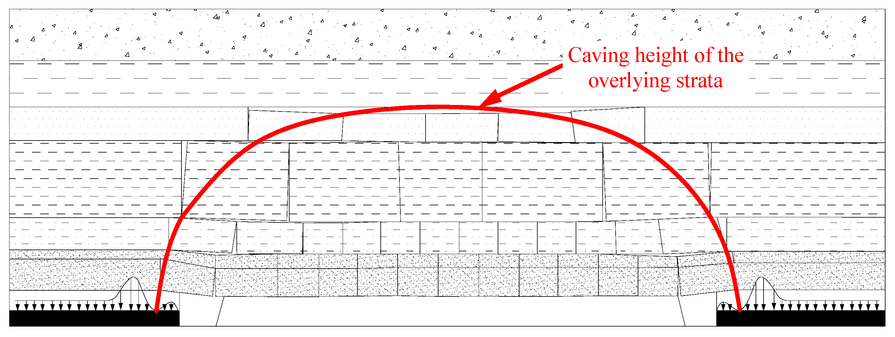
The maximum value of stress acting on the wall of the gob-side entry retaining is shown in Figure 16. It can be seen that the there are three stages according to the magnitude of the force acting on the wall. First (Stage I: 0~150 m), the maximum values measured by pressure cells at the top and bottom of the wall were both at 12.0 MPa. Next, (Stage II: 150~280 m), the maximum values measured by pressure cells at the top and bottom of the wall were 28.0 MPa and 21.8 MPa, respectively. Third (Stage III: 280~360 m), the maximum values measured by pressure cells at the top and bottom of the wall were 15.0 MPa and 9.0 MPa, respectively. Taken together, the stress at Stage II was larger than that of Stage I and Stage III. The occurrence of these three stages is closely related to the structure of the overlying strata. As shown in Figure 17, the caving height of the overlying strata in the middle of the stope is larger than that of the two ends, so the stress action on the wall in the middle of the stope is larger [20]. This phenomenon has a certain guiding significance for the support-strength design of the gob-side entry-retaining wall.
In addition, taking point A as an example in order to analyse the changing values of the stress acting on the wall, it can be seen that with the advance of the working face, the stress acting on the wall rapidly increased. When the distance between measuring points and the working face was 21 m, the stress reached a maximum value of 21.8 MPa. Then, with the caving of the roof, the wall and the caving gangue in the gob supported the upper rock together, and the stress acting on the wall was reduced to 11.0 MPa. Finally, it can be seen that the mean stresses measured by pressure cells at the top and bottom of the wall were 7.3 MPa and 8.3 MPa, respectively. The stress of the wall was not particularly great, and the hollow wall could meet the strength requirements. The pressure cells, which had readings of 0, were not counted.
4. Conclusions
In coal mine gob-side entry-retaining practices, reducing the retaining cost and improving the production rate have long been crucial issues that need to be further and continuously addressed by engineers and researchers. With this in mind, a new gob-side entry-retaining approach was proposed in this paper, which included the use of a lightweight and high-strength foam concrete along with a mortise-and-tenon structure hollow block wall.
The experimental results show that the preparation of foam concrete of density 1200 kg/m3, with uniaxial compressive strength greater than 15 MPa, can be created by using a chemical foaming method by adding silica fume, slag and fly ash to a system of “cement and sand” structure collocation along with optimizing the proportioning. The density of the foam concrete is reduced by 50% relative to that of common concrete, which can greatly reduce the weight of the blocks. Furthermore, the failure mode of LHFC is similar to that of ordinary concrete, exhibiting a longitudinal splitting failure, and the angle between the failure surface and the load vertical is 53° to 76°, which shows the brittleness of the material. When only one mineral admixture was added, the 28-d compressive strength of LHFC is silica fume > slag > fly ash. When two mineral admixtures were added, the 28-d compressive strength of LHFC is silica fume + slag > silica fume + fly ash > slag + fly ash.
A mortise-and-tenon structure block wall was developed. In this wall, the mortar bonding between the blocks, coupled with the connection role of the block, can effectively avoid the movement between blocks and greatly improve the integrity of the wall. The wall can improve stability by increasing the width-to-height ratio of the wall and save 44.44% of the material. It can be seen that its economic benefits are considerable, and at the same time, it can save manpower and improve labour efficiency.
The effectiveness of the proposed gob-side entry-retaining technology was tested in a case study of the 3203 panel in the Dongtan Coal Mine. It was found that the labour intensity of the workers was greatly reduced, and the efficiency of the retaining entry was remarkably improved. The application proves that the lightweight and high-strength foam concrete is well suited for entry retaining, and the wall structure and parameters are reasonable.
Acknowledgments
This work is supported by the National Natural Science Foundation of China (No. 51379117 and No. 51479108), the Taishan Scholar Talent Team Support Plan for Advantaged and Unique Discipline Areas, and the Scientific Research Foundation of Shandong University of Science and Technology for Recruited Talents (2015RCJJ048).
Author Contributions
All the authors contributed to publishing this paper. Hengjie Luan and Yujing Jiang contributed to the formulation of the overarching research goals and aims; Guofeng Li contributed to the experimental study of the foam concrete; Huili Lin contributed to the industrial test.
Conflicts of Interest
The authors declare no conflicts of interest.
References
- Vakili, A.; Hebblewhite, B.K. A new cavability assessment criterion for Longwall Top Coal Caving. Int. J. Rock Mech. Min. Sci. 2010, 47, 1317–1329. [Google Scholar] [CrossRef]
- Shabanimashcool, M.; Li, C.C. Numerical modelling of longwall mining and stability analysis of the gates in a coal mine. Int. J. Rock Mech. Min. Sci. 2012, 51, 24–34. [Google Scholar] [CrossRef]
- Gao, Y.; Liu, D.; Zhang, X.; He, M. Analysis and Optimization of Entry Stability in Underground Longwall Mining. Sustainability 2017, 9, 2079. [Google Scholar] [CrossRef]
- Deng, Y.; Wang, S. Feasibility analysis of gob-side entry retaining on a working face in a steep coal seam. Int. J. Min. Sci. Technol. 2014, 24, 499–503. [Google Scholar] [CrossRef]
- Ning, J.; Wang, J.; Bu, T.; Hu, S.; Liu, X. An Innovative Support Structure for Gob-Side Entry Retention in Steep Coal Seam Mining. Minerals 2017, 7, 75. [Google Scholar] [CrossRef]
- Zhang, Z.; Shimada, H.; Sasaoka, T.; Hamanaka, A. Stability Control of Retained Goaf-Side Gateroad under Different Roof Conditions in Deep Underground Y Type Longwall Mining. Sustainability 2017, 9, 1671. [Google Scholar] [CrossRef]
- Wang, P.; Jiang, L.; Jiang, J.; Zheng, P.; Li, W. Strata Behaviors and Rock Burst–Inducing Mechanism under the Coupling Effect of a Hard, Thick Stratum and a Normal Fault. Int. J. Geomech. 2017, 18, 04017135. [Google Scholar] [CrossRef]
- Tan, Y.L.; Yu, F.H.; Ning, J.G.; Zhao, T.B. Design and construction of entry retaining wall along a gob side under hard roof stratum. Int. J. Rock Mech. Min. Sci. 2015, 77, 115–121. [Google Scholar] [CrossRef]
- Zhang, Z.Y.; Hideki, S.; Qian, D.Y.; Takashi, S. Application of the retained gob-side gateroad in a deep underground coalmine. Int. J. Min. Reclam. Environ. 2016, 30, 371–389. [Google Scholar] [CrossRef]
- Wang, H.; Zhang, D.; Liu, L.; Guo, W.; Fan, G.; Song, K.; Wang, X. Stabilization of Gob-Side Entry with an Artificial Side for Sustaining Mining Work. Sustainability 2016, 8, 627. [Google Scholar] [CrossRef]
- Yang, H.; Cao, S.; Li, Y.; Sun, C.; Guo, P. Soft Roof Failure Mechanism and Supporting Method for Gob-Side Entry Retaining. Minerals 2015, 5, 707–722. [Google Scholar] [CrossRef]
- Yang, H.; Cao, S.; Wang, S.; Fan, Y.; Wang, S.; Chen, X. Adaptation assessment of gob-side entry retaining based on geological factors. Eng. Geol. 2016, 209, 143–151. [Google Scholar] [CrossRef]
- Han, C.; Zhang, N.; Li, B.; Si, G.; Zheng, X. Pressure relief and structure stability mechanism of hard roof for gob-side entry retaining. J. Cent. South Univ. 2015, 22, 4445–4455. [Google Scholar] [CrossRef]
- Zhang, Z.; Bai, J.; Chen, Y.; Yan, S. An innovative approach for gob-side entry retaining in highly gassy fully-mechanized longwall top-coal caving. Int. J. Rock Mech. Min. Sci. 2015, 80, 1–11. [Google Scholar] [CrossRef]
- Zhang, Y.; Tang, J.; Xiao, D.; Sun, L.; Zhang, W. Spontaneous caving and gob-side entry retaining of thin seam with large inclined angle. Int. J. Min. Sci. Technol. 2014, 24, 441–445. [Google Scholar] [CrossRef]
- Feng, X.; Zhang, N. Position-optimization on retained entry and backfilling wall in gob-side entry retaining techniques. Int. J. Coal Sci. Technol. 2015, 2, 186–195. [Google Scholar] [CrossRef]
- Yaseen, Z.M.; Deo, R.C.; Hilal, A.; Abd, A.M.; Bueno, L.C.; Salcedo-Sanz, S.; Nehdi, M.L. Predicting compressive strength of lightweight foamed concrete using extreme learning machine model. Adv. Eng. Softw. 2018, 115, 112–125. [Google Scholar] [CrossRef]
- Prabha, P.; Palani, G.S.; Lakshmanan, N.; Senthil, R. Behaviour of steel-foam concrete composite panel under in-plane lateral load. J. Constr. Steel Res. 2017, 139, 437–448. [Google Scholar]
- Nguyen, L.H.; Beaucour, A.L.; Ortola, S.; Noumowé, A. Experimental study on the thermal properties of lightweight aggregate concretes at different moisture contents and ambient temperatures. Constr. Build. Mater. 2017, 151, 720–731. [Google Scholar] [CrossRef]
- Xu, D.; Peng, S.; Xiang, S.; He, Y. A Novel Caving Model of Overburden Strata Movement Induced by Coal Mining. Energies 2017, 10, 476. [Google Scholar] [CrossRef]
Figure 1.
Picture of concrete-block wall for gob-side entry retaining (the number of concrete blocks used is very large).
Figure 1.
Picture of concrete-block wall for gob-side entry retaining (the number of concrete blocks used is very large).
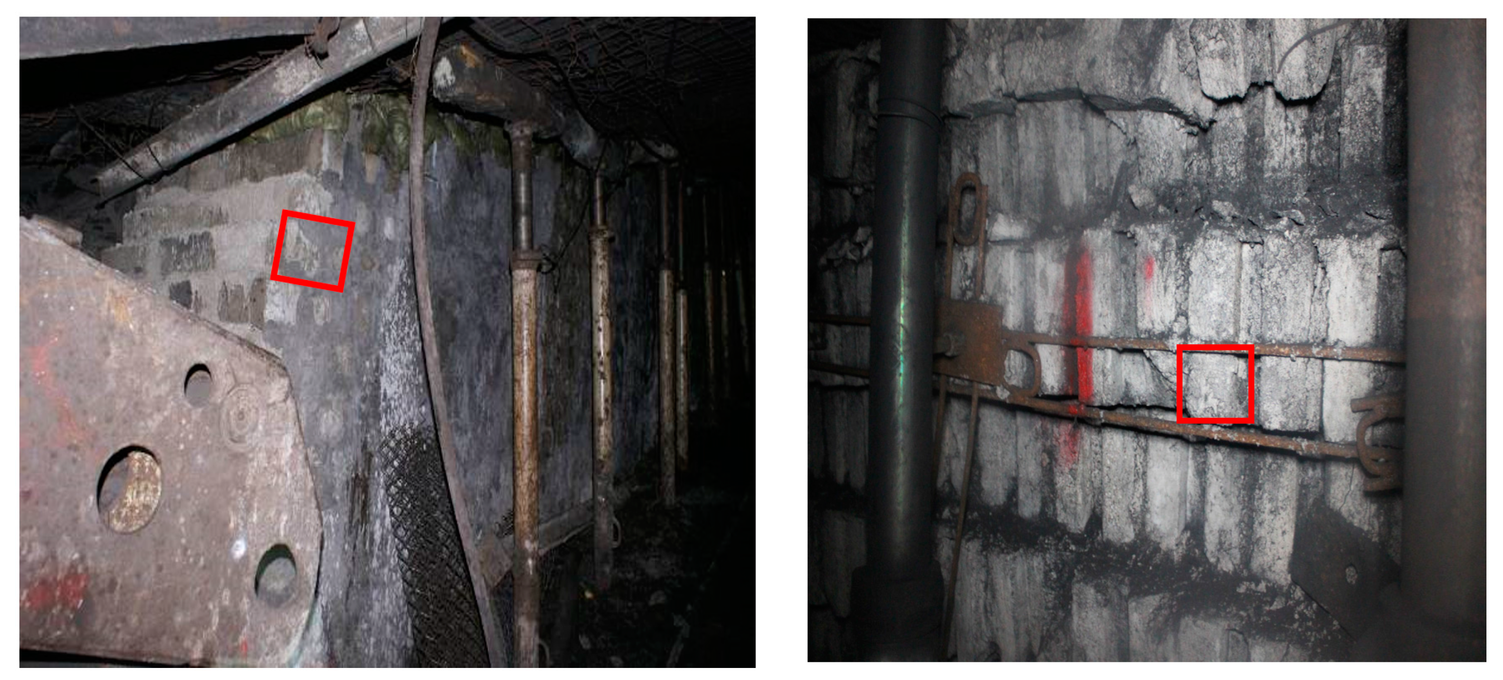
Figure 2.
Position of the Dongtan Coal Mine.
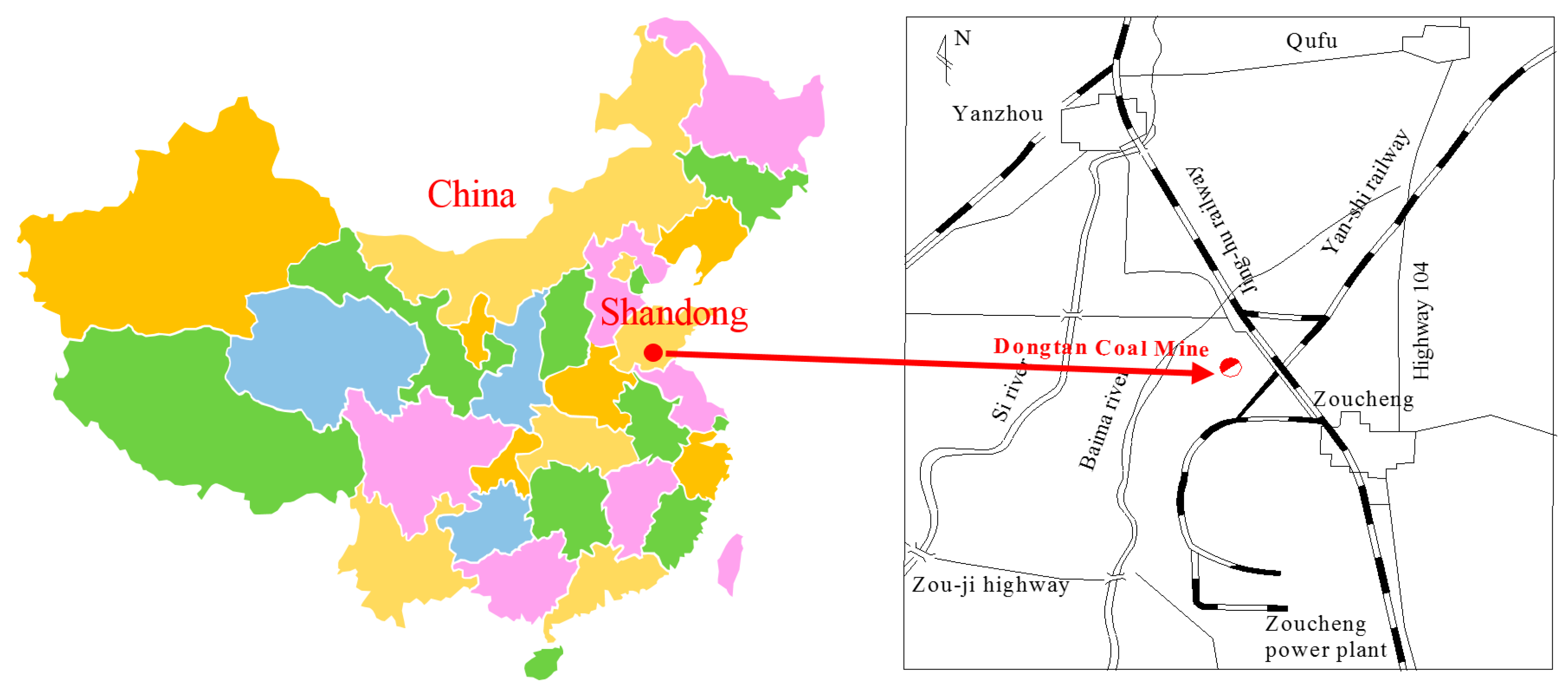
Figure 3.
The working-face arrangement and the stratigraphic column with the lithology character.
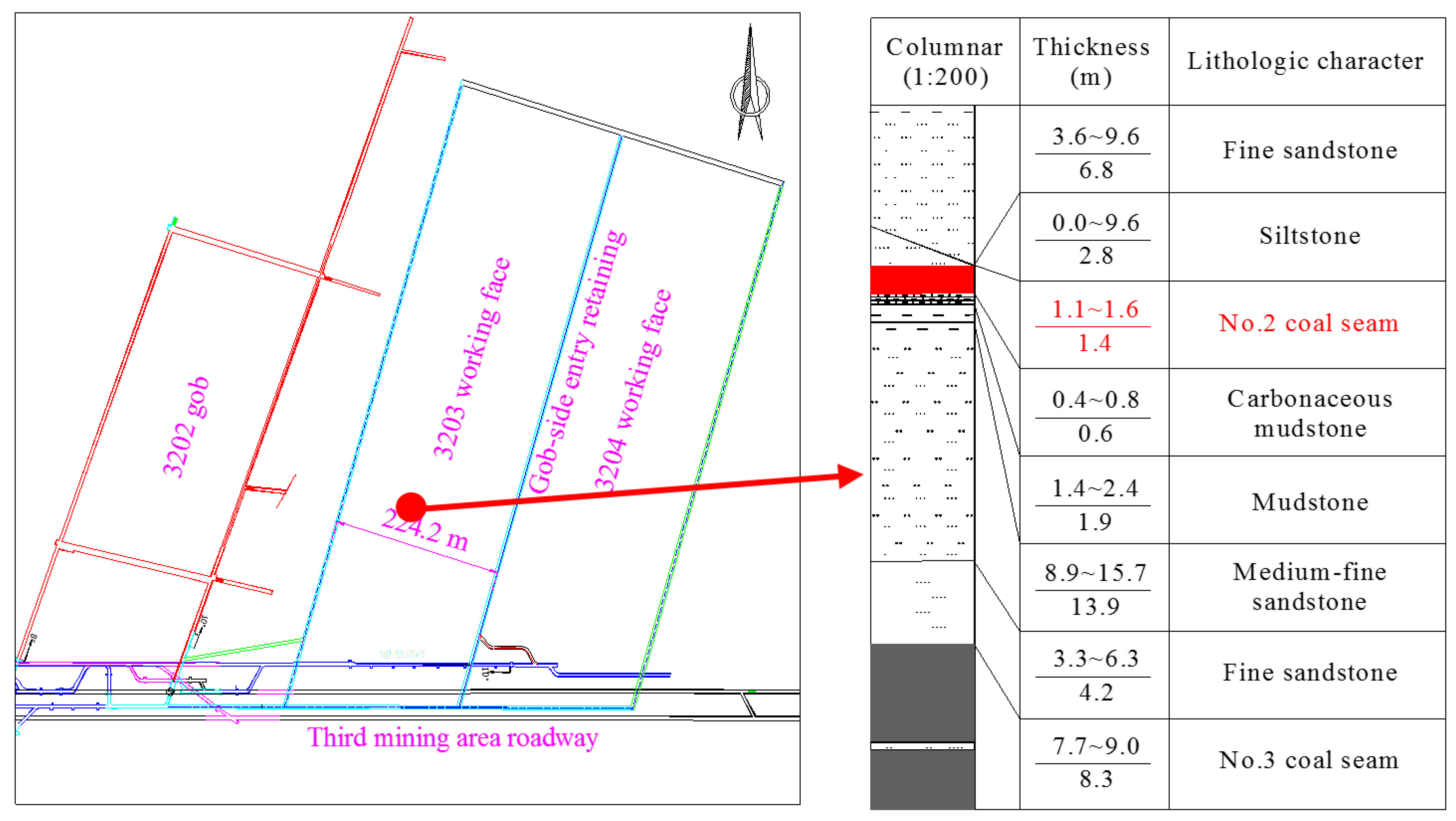
Figure 4.
Foam concrete: (a) foam concrete specimen; (b) microstructure diagram.
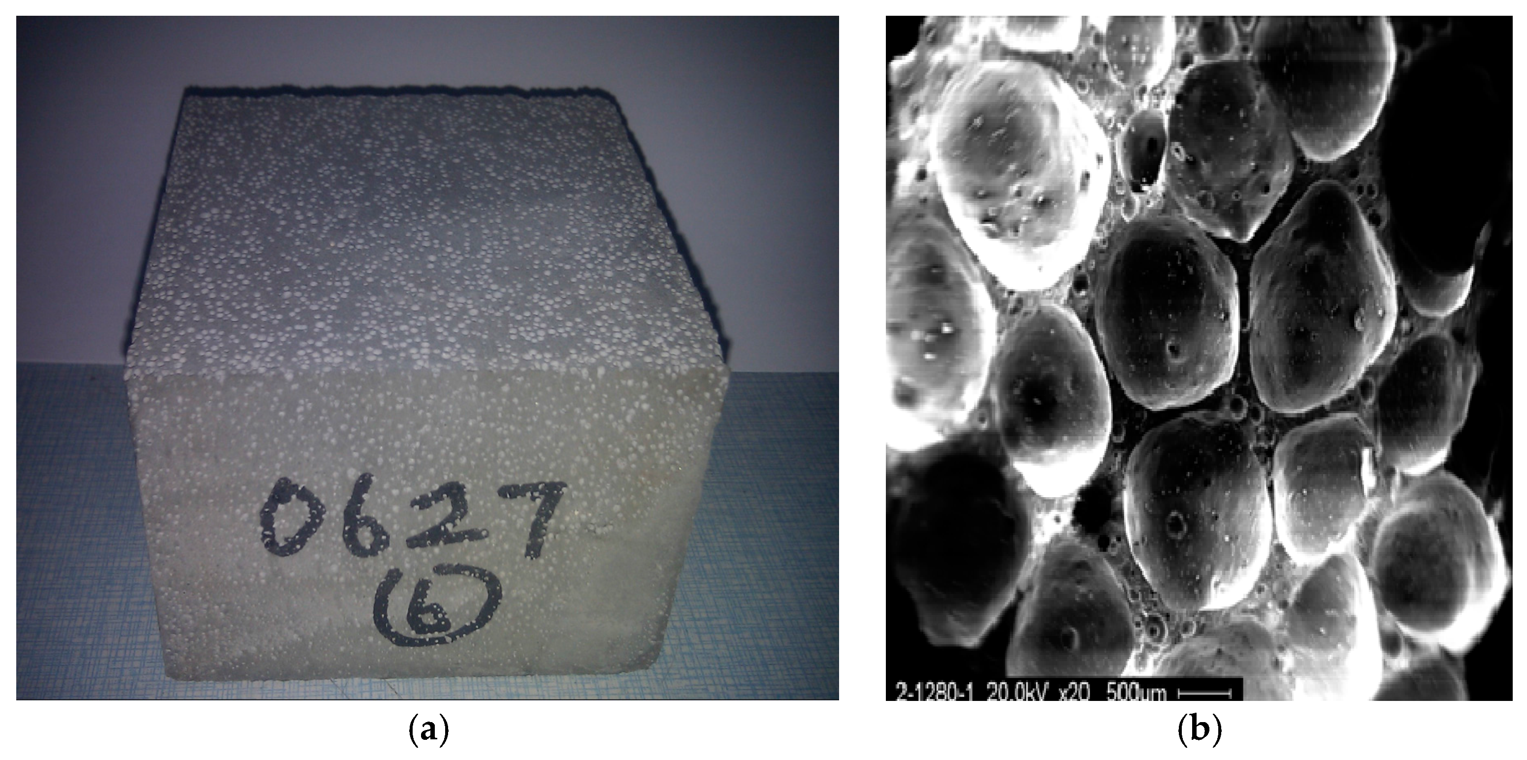
Figure 5.
Specimen failure modes: (a) crack-generation stage; (b) crack-development stage; (c) crack-coalescence stage.
Figure 5.
Specimen failure modes: (a) crack-generation stage; (b) crack-development stage; (c) crack-coalescence stage.
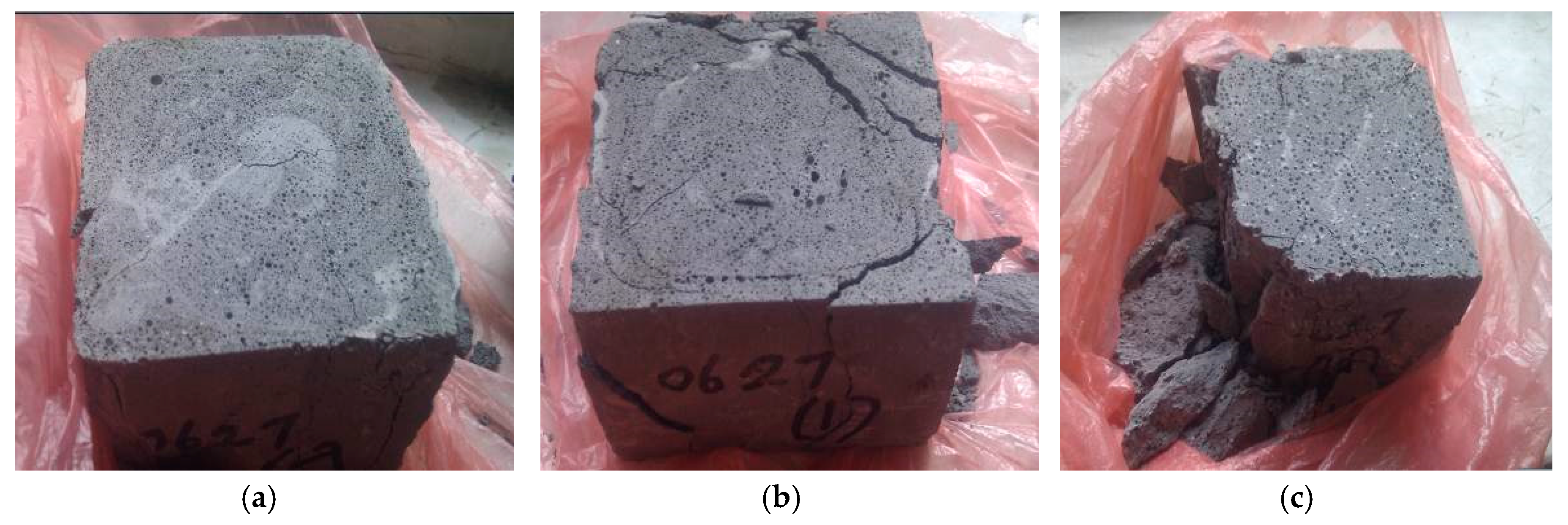
Figure 6.
Stress-strain curve of 7# foam concrete specimen at different periods.
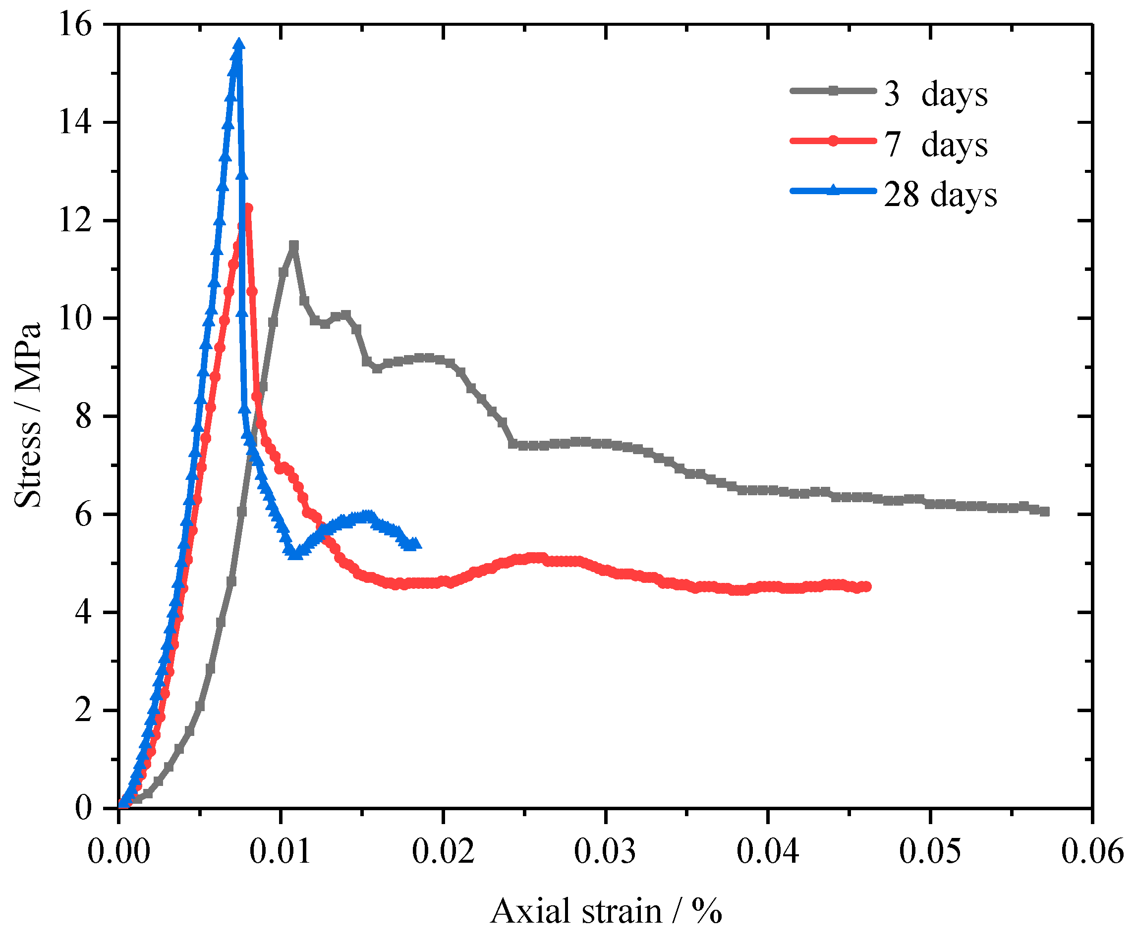
Figure 7.
Scanning electron microscope (SEM) images of foam concrete with different admixture: (a) silica fume; (b) fly ash; (c) slag.
Figure 7.
Scanning electron microscope (SEM) images of foam concrete with different admixture: (a) silica fume; (b) fly ash; (c) slag.
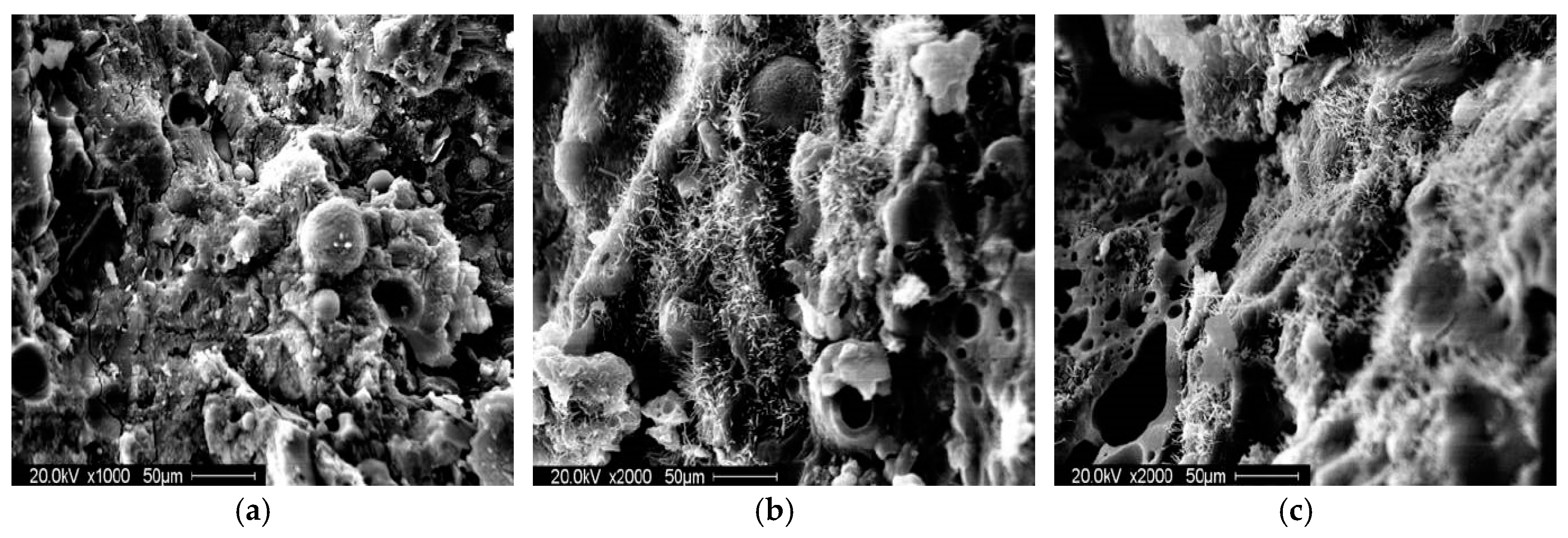
Figure 8.
SEM image of foam concrete: (a) with silica fume and slag; (b) with fly ash and slag.
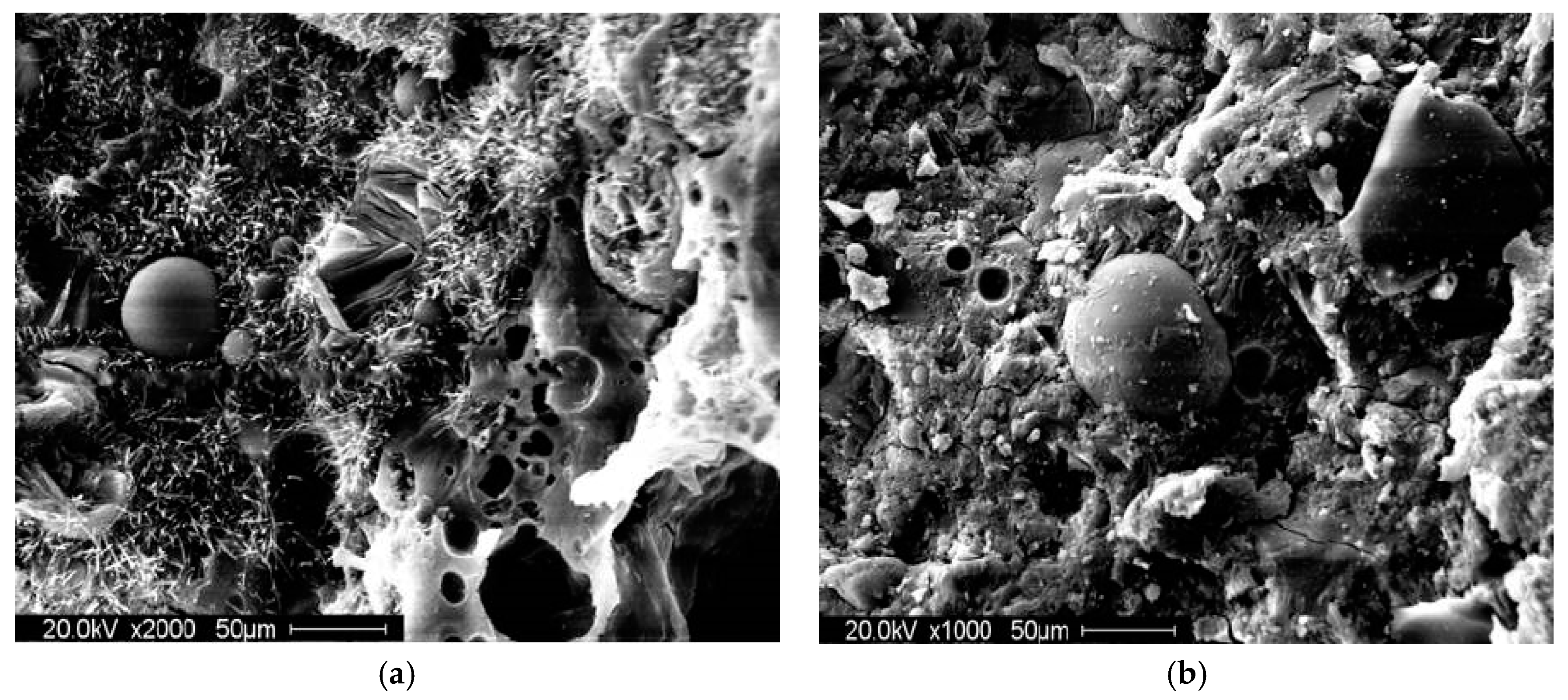
Figure 9.
Picture of the mortise-and-tenon structure hollow wall.
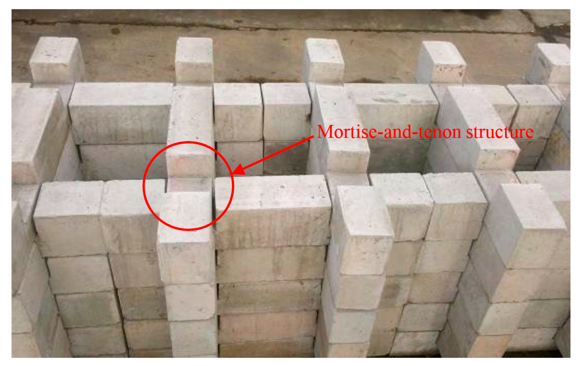
Figure 10.
Concrete blocks of different specifications: (a) 600 mm; (b) 812.5 mm; (c) 1200 mm; (d) steel bar in the block.
Figure 10.
Concrete blocks of different specifications: (a) 600 mm; (b) 812.5 mm; (c) 1200 mm; (d) steel bar in the block.
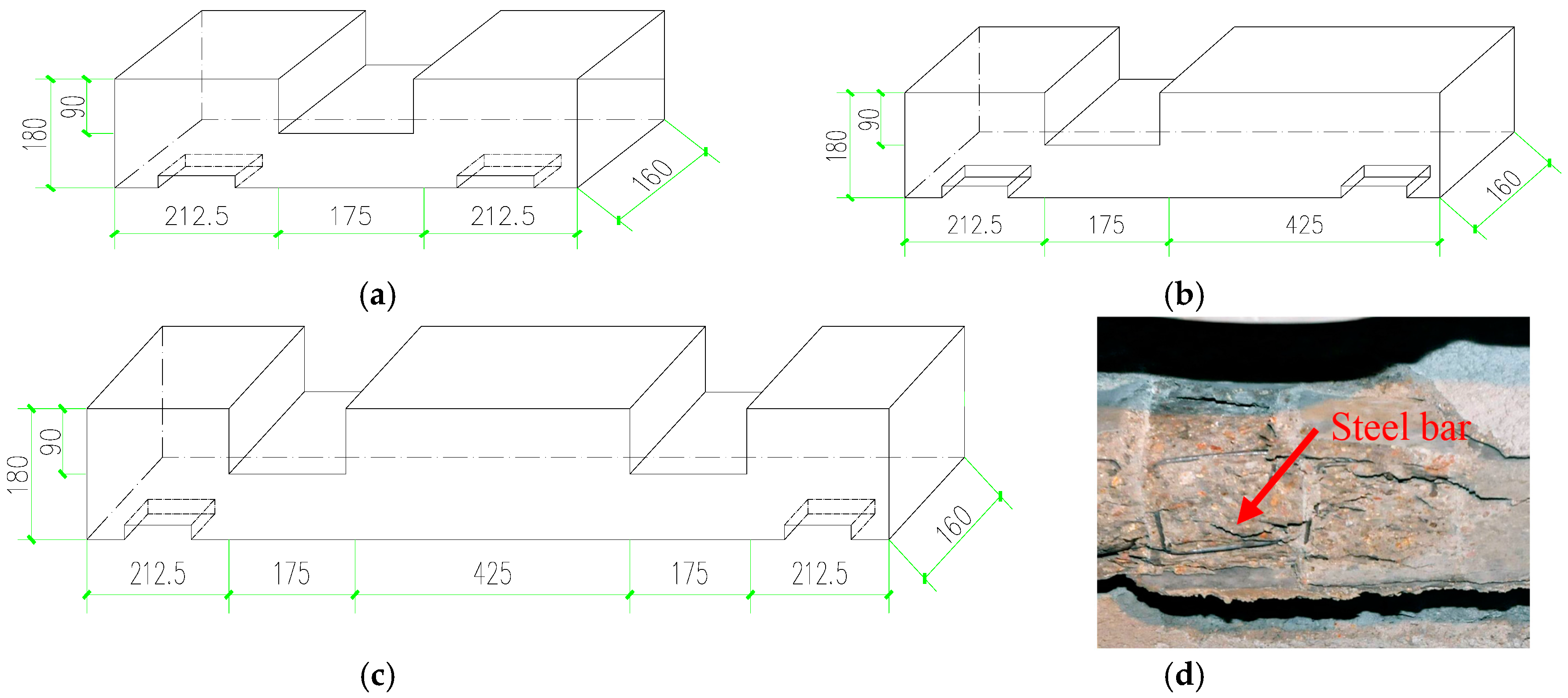
Figure 11.
Picture of the mortise-and-tenon structure hollow wall.
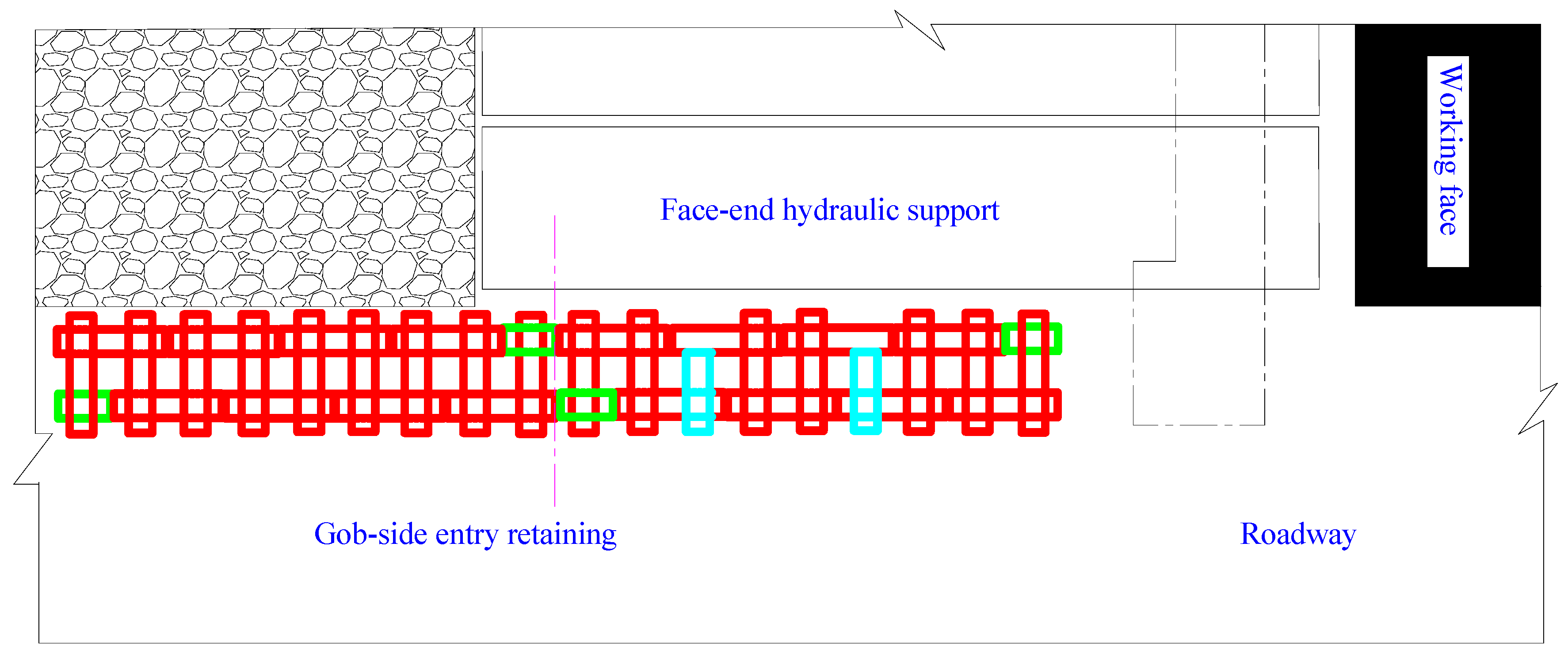
Figure 12.
Picture of the mortise-and-tenon structure hollow wall.
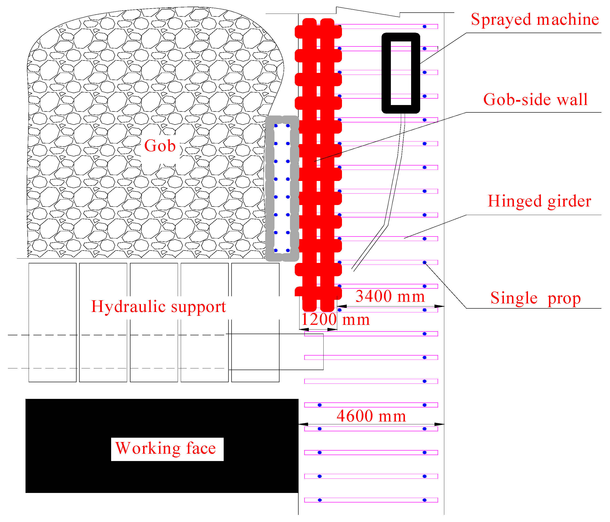
Figure 13.
Pictures of gob-side entry effect: (a) foam concrete block wall; (b) gob-side entry.
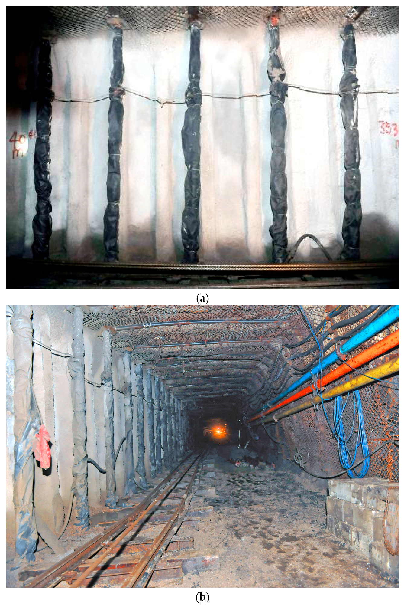
Figure 14.
Pictures of mine pressure observation: (a) deformation observation of roadway; (b) stress observation of wall.
Figure 14.
Pictures of mine pressure observation: (a) deformation observation of roadway; (b) stress observation of wall.

Figure 15.
Deformation law of surrounding rock of the gob-side entry.
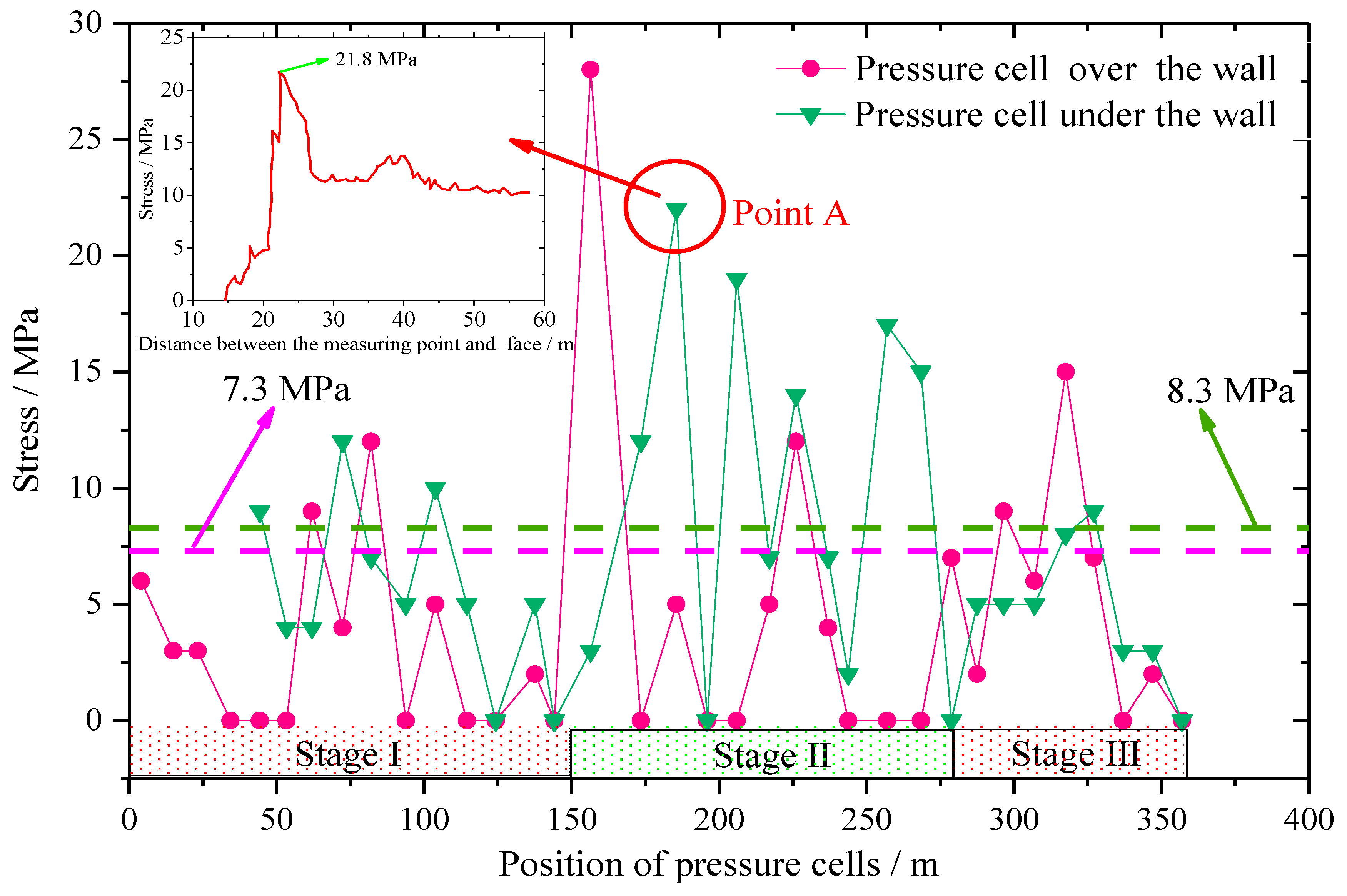
Figure 16.
The maximum value of stress acting on the wall.
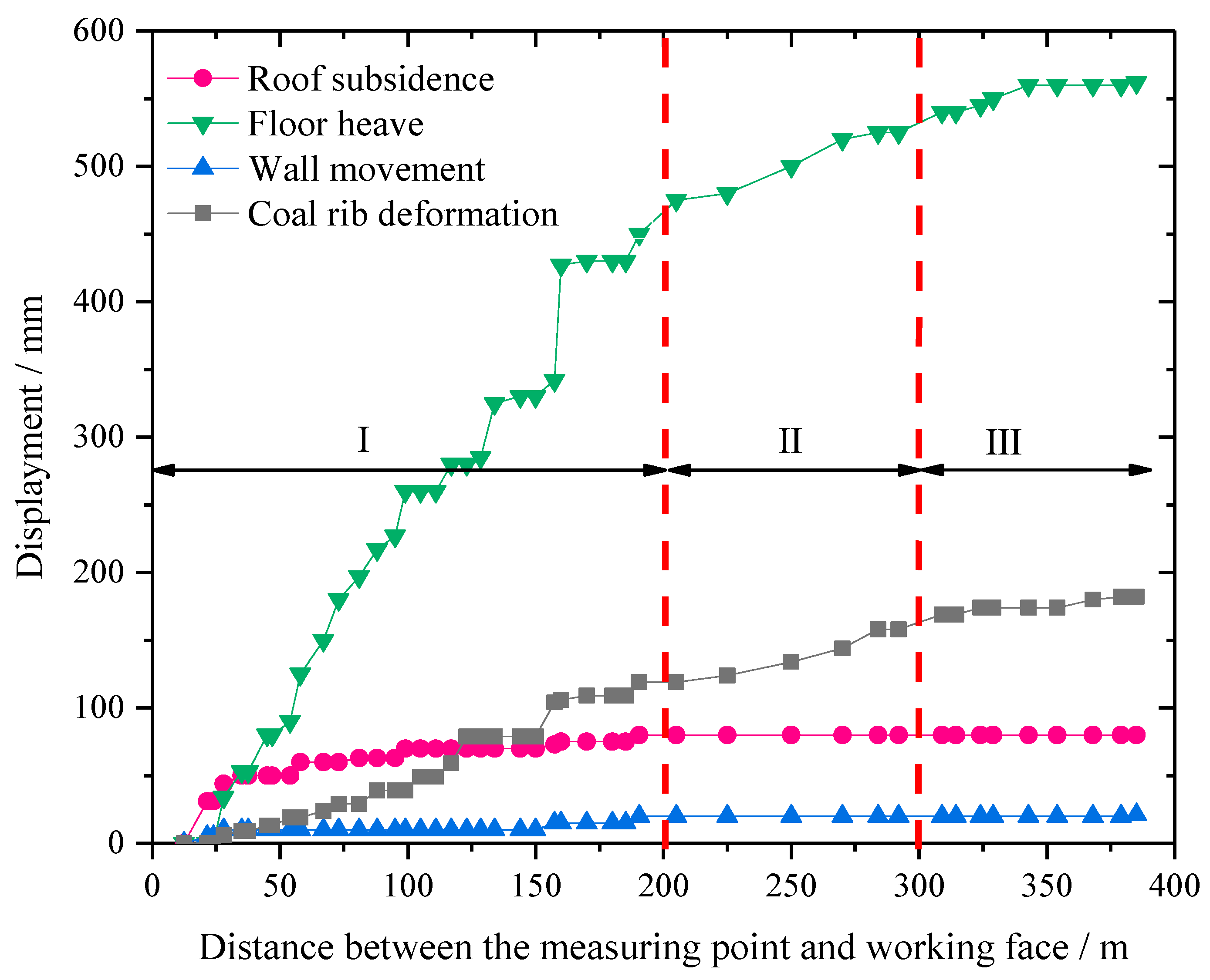
Figure 17.
The structure characteristics of the overlying strata.

Table 1.
Mix proportion of foam concrete.
| Specimen Number | Cement/g | Admixture/g | Sand/g | Foaming Agent/g | Polypropylene Fibre/g | Superplasticizer/g | Curing Agent/g | Activator/g |
|---|---|---|---|---|---|---|---|---|
| 1# | 960 | 0 | 240 | 45 | 5 | 1.6 | 20 | 6 |
| 2# | 840 | 120 (silica fume) | 240 | 45 | 5 | 1.6 | 20 | 6 |
| 3# | 840 | 120 (slag) | 240 | 45 | 5 | 1.6 | 20 | 6 |
| 4# | 840 | 120 (fly ash) | 240 | 45 | 5 | 1.6 | 20 | 6 |
| 5# | 840 | 60 (slag) + 60 (fly ash) | 240 | 45 | 5 | 1.6 | 20 | 6 |
| 6# | 840 | 60 (silica fume) + 60 (fly ash) | 240 | 45 | 5 | 1.6 | 20 | 6 |
| 7# | 840 | 60 (silica fume) + 60 (slag) | 240 | 45 | 5 | 1.6 | 20 | 6 |
Table 2.
Uniaxial compressive strength of foam concrete under different ratios.
| Specimen Number | Uniaxial Compressive Strength/MPa | ||
|---|---|---|---|
| 3 Days | 7 Days | 28 Days | |
| 1# | 8.52 | 10.51 | 12.27 |
| 2# | 9.89 | 12.83 | 14.72 |
| 3# | 9.64 | 13.32 | 14.38 |
| 4# | 7.20 | 10.68 | 13.26 |
| 5# | 11.04 | 13.96 | 14.75 |
| 6# | 10.80 | 12.40 | 15.02 |
| 7# | 11.40 | 12.20 | 15.55 |
© 2018 by the authors. Licensee MDPI, Basel, Switzerland. This article is an open access article distributed under the terms and conditions of the Creative Commons Attribution (CC BY) license (http://creativecommons.org/licenses/by/4.0/).
Share and Cite
MDPI and ACS Style
Luan, H.; Jiang, Y.; Lin, H.; Li, G. Development of a New Gob-Side Entry-Retaining Approach and Its Application. Sustainability 2018, 10, 470. https://doi.org/10.3390/su10020470
AMA Style
Luan H, Jiang Y, Lin H, Li G. Development of a New Gob-Side Entry-Retaining Approach and Its Application. Sustainability. 2018; 10(2):470. https://doi.org/10.3390/su10020470
Chicago/Turabian StyleLuan, Hengjie, Yujing Jiang, Huili Lin, and Guofeng Li. 2018. "Development of a New Gob-Side Entry-Retaining Approach and Its Application" Sustainability 10, no. 2: 470. https://doi.org/10.3390/su10020470
Note that from the first issue of 2016, this journal uses article numbers instead of page numbers. See further details here.