Article

Theoretical Investigation of Gas Filling and Leaking in Inertial Confinement Fusion Hohlraum

1
Key Laboratory of Energy Thermal Conversion and Control of Ministry of Education, School of Energy and Environment, Southeast University, Nanjing 210096, China
2
School of Hydraulic, Energy and Power Engineering, Yangzhou University, Yangzhou 225127, China
*
Author to whom correspondence should be addressed.
Sustainability 2018, 10(10), 3763; https://doi.org/10.3390/su10103763
Submission received: 28 August 2018 / Revised: 15 October 2018 / Accepted: 16 October 2018 / Published: 18 October 2018
(This article belongs to the Section Energy Sustainability)

Abstract

:
The gas filling and retention of inertial confinement fusion (ICF) hohlraum is an important issue in ICF studies. In this study, a theoretical model of gas filling and leaking processes for ICF hohlraum is developed based on the unified flow theory. The effects of the fill tube size and the filling pressure on the gas filling and leaking performance are investigated. The results indicate that an increase in the variation rate of the filling/leaking pressure leads to a larger maximum pressure difference between the inside and outside of the ICF hohlraum during the filling/leaking process. The critical pressure difference of the filling process is nearly equal to that of the leaking process. Increase in fill tube diameter and decrease in its length both lead to a lower probability of the rupture of polymeric films at two ends of the hohlraum, and thus increases the security of the hohlraum. In addition, a departure in cross sectional shape of fill tube from circle to rectangle triggers an increase in pressure difference between the inside and outside of the ICF hohlraum, which raises the risk of polymeric films rupture and decreases the security of the hohlraum structure.

1. Introduction

Inertial confinement fusion (ICF) [1,2,3] is considered as a promising way to achieve controlled thermonuclear fusion that can provide individuals with high-quality sustainable energy [4,5,6]. In inertial confinement fusion [7], there are two approaches to drive an ICF implosion, namely direct drive and indirect drive. In the direct drive approach, laser beams are directly aimed at a spherical target containing fusion fuel that is typically from the emulsion droplet prepared by the microfluidics [8,9,10,11]. In the indirect drive approach [12,13], energy from a laser is first absorbed by a typically cylindrical-shaped enclosure termed as a hohlraum to produce X-rays using the high-Z material inside the hohlraum to irradiate the target [14,15]. Given the relaxed requirements on laser-beam uniformity, the indirect drive approach is the subject of intense interest in ICF recently. To ensure the symmetry of the implosion, ICF hohlraum is initially filled with a low-density and low-Z gas as a symmetry-control technique to suppress the interaction of the plasma in the hohlraum, thereby resulting in a reduction in the energy loss of the laser [16,17]. Considering that, the gas filling and retention of ICF hohlraum has become a key issue in the ICF studies [18]. Aiming to select and optimize the process parameters of ICF hohlraum, it is of particular importance to study the gas flow behaviors during gas filling and leaking processes of the ICF hohlraum.
To prevent the gas in the hohlraum from leaking, a gas barrier film (mainly a polyimide film) is placed on the diagnosis port and laser entrance port of the hohlraum. When the variation rate of the gas filling/leaking pressure is excessively high, the pressure difference across the film exceeds its pressure tolerance, thereby resulting in the rupture of the film and failure of gas filling or leaking. A few investigations focus on gas filling and leaking processes of ICF hohlraum [19]. With respect to the Nova experiments, the hydrocarbons were used as low-Z gas fill [20,21,22]. Unfortunately, it is not possible to provide a definitive answer with respect to the gas flow behaviors during the gas filling and leaking processes due to restrictions on measurement of the gas pressure in the hohlraum and the gas mass flow in the fill tube using existing experimental measurement devices [23]. Thus, a theoretical method is necessary to determine the gas filling and leaking processes and hence to evaluate the extreme rupture condition of the hohlraum film.
During gas filling and leaking processes, the pressure in the hohlraum changes significantly in the range of 0 atm–1 atm. It should be noted that the gas flow at standard atmospheric pressure is in the continuum flow region, however the gas flow at nearly 0 atm is in the free-molecular flow region of rarefied gas [24,25,26]. In addition to the continuum flow region, the continuum approach of the classical Navier–Stokes equations is no longer valid in the transitional flow region and free molecular flow region, which is attributed to the gradually dominant gas rarefaction effect [27,28]. However, there is a paucity of theoretical studies on gas filling and leaking processes in the hohlraum where the multiscale gas flow involved.
While several attempts have been conducted to investigate the gas filling and retention of the ICF hohlraum, it is impossible to measure the dynamic gas pressure in the hohlraum directly due to the small size of the hohlraum [29,30,31]. Thus, the applicability of the pressure variation rate during the gas filling and leaking processes with the required critical pressure value for safe gas filling/leaking of the hohlraum has not been well clarified, resulting in the potential risk of the hohlraum rupture. In addition, in order to optimally design the gas fill tube and the hohlraum, the gas flow behaviors as well as the dependences of the geometries of the gas fill tube and the hohlraum on the performance of the gas filling and leaking processes are still waiting to be explored. For these reasons, it is extremely important to develop a quantitative analysis and prediction method that considers the gas rarefaction effect, to provide a guideline for the parameters selection and optimization of gas filling and leaking processes in the ICF hohlraum.
To provide a guideline for the parameters selection and optimization of gas filling and leaking processes in the ICF hohlraum, it is extremely important to develop a quantitative analysis and prediction method that considers the gas rarefaction effect. In this study, a theoretical model of the gas flow behaviors during gas filling and leaking processes of ICF hohlraum is developed. Furthermore, the model is numerically analyzed to investigate the effects of the gas fill tube size and the filling pressure on gas filling and leaking processes. The current study provides a deep understanding of the gas filling and leaking processes of the ICF hohlraum.

2. Mathematical Model

To further insight into the gas flow behaviors in ICF hohlraum, a theoretical model of gas filling and leaking processes of ICF hohlraum are developed in this study. As shown in Figure 1, the hohlraum with the shape of a hollow cylindrical cavity is placed in an infinitely large gas filling chamber and connected to the gas filling chamber through a fill tube. The initial pressure in the hohlraum is Pi, and the ambient pressure outside the hohlraum, i.e. the pressure of the gas filling chamber, is Po. The cylindrical hohlraum is of a cross-sectional diameter of dh = 2.2 mm and a length of Lh = 4.6 mm. The diameter and the length of the fill tube for the hohlraum are dx = 0.1 mm and Lx = 500 mm, respectively. The temperature of the hohlraum during the filling and leaking processes is maintained constant, i.e., Ti = To = 298.15 K. The hohlraum is filled with helium as low-Z gas, and this is considered as an ideal gas and satisfies the ideal gas state equation. The pressure difference between the inside and outside of the hohlraum is defined as ΔP = PoPi. It is assumed that the film of the hohlraum ruptures at a pressure difference exceeding 0.5 atm, and thus the critical pressure value for safe gas filling/ leaking of the hohlraum is set as ΔPc = 0.5 atm [32].

2.1. Governing Equations

To evaluate the rarefaction effects during the gas filling and leaking processes of ICF hohlraum, the Knudsen number (Kn) is introduced as [33,34]
K n = λ d x
where dx denotes the diameter of the fill tube and λ denotes the molecular average free path. Based on the theory of gas dynamics, the molecular average free path λ is related to the dynamic viscosity μ, pressure P, and temperature T as
λ = μ P π R T 2
The relationship between the Knudsen number and pressure is
K n = μ P d x π R T 2 ,
During the gas filling and leaking processes, the Knudsen number ranges from 0.001 to 50, indicating that the gas flow goes through the continuum flow region, slip flow region, transition flow region, and free-molecular flow region [35,36]. When the Knudsen number is sufficiently large, it is not possible to ignore the gas rarefaction effect, and this results in invalid Navier–Stokes equations based on continuity assumption [37,38]. Therefore, Beskok, and Karniadak is proposed a unified flow model [39] in the entire Knudsen regime, and this effectively predicts the velocity distribution, pressure drop, and mass flow rate in microtubules. In the model, a rarefaction coefficient is introduced to correct the gas velocity distribution in the transitional flow zone and free molecular flow zone. The results are in good agreement with the analytical solutions of the linearized Boltzmann equation. Thus, the gas flow behaviors in the fill tube during the gas filling and leaking processes of ICF hohlraum are described by the unified flow model in the entire Knudsen regime. This is coupled with the description of the gas state equation inside the hohlraum to analyze the gas flow behaviors during gas filling and leaking processes of ICF hohlraum.
The differentiating gas state equation in the hohlraum PV = mRT is derived as
d P d t = 1 V ( m R d T d t + R T d m d t )
The gas filling and leaking processes are simplified by ignoring the temperature change, so Equation (4) is modified as
d P d t = R T V d m d t = R T V M ˙
where M ˙ denotes the gas mass flow rate. When the gas flow goes into the hohlraum, M ˙ is positive and vice versa.
Based on the unified flow theory model, the gas mass flow rate in the gas fill tube is calculated by
M ˙ = π a d 4 P avg 8 μ 0 R T × Δ P L ( 1 + α K n avg ) ( 1 + 4 K n avg 1 b K n avg )
where b = −1, R denotes the gas constant of helium, T denotes the system temperature, Pavg denotes the average pressure drop, i.e., the average pressure between the inlet and outlet of the fill tube in which Pavg = (Pi + Po)/2. Furthermore, μ0 denotes the dynamic viscosity that is assumed to be constant in this study, and Knavg is obtained from Pavg using Equation (3).
The parameter α varies with Kn, and this is calculated by
α = α 0 2 π tan 1 ( α 1 K n ¯ β )
where α1 = 4, β = 0.4, and α0 = 1.19, and these parameters are derived from the air flow experiment in the finite-length tube by Tison [40].

2.2. Boundary Conditions and Numerical Solution

The pressures of the hohlraum and gas filling chamber are both 0 atm at the initial time of the gas filling process. Subsequently, the gas is filled into the gas filling chamber until the pressure of gas filling chamber increases to 15 atm. The pressure variation rate of gas filling chamber is Φ. Through the gas fill tube, the hohlraum is filled with gas gradually until the pressure inside and outside of the hohlraum are balanced.
P i | t = 0 = P o | t = 0 = 0   atm
P i | t = P o | t = 15   atm
d P o d t = Φ
During the gas leaking process, the pressures of the hohlraum and gas filling chamber are both initially assumed as 15 atm. Subsequently, the gas in the gas filling chamber leaks into vacuum until the pressure of gas filling chamber decreases to 0 atm. The pressure variation rate of gas filling chamber is the same as Φ. Through the gas fill tube, the gas in the hohlraum also leaks into the gas filling chamber until the pressure inside and outside of the hohlraum are balanced.
P i | t = 0 = P o | t = 0 = 15   atm
P i | t = P o | t = 0   atm
d P o d t = Φ
With above external pressure boundary conditions, Equations (2), (3), and (6) are solved using the Newton-iterative method to obtain the time evolution of pressure in the hohlraum and in the gas filling chamber.

2.3. Case Validation

The dimensionless gas mass flow rate in Equation (6) is
M ¯ = 3 π 64 K n ¯ ( 1 + α K n ¯ ) ( 1 + 4 K n ¯ 1 b K n ¯ )
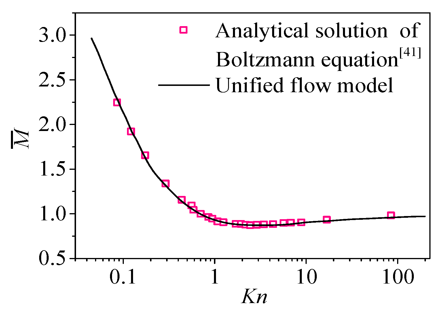
To validate the model, a theoretical case of the linearized Boltzmann solution on the gas flow in an elongated channel obtained by Loyalka and Hamoodi [41] is simulated and examined in the present study. As shown in Figure 2, the present simulation results for the dimensionless gas mass flow rate agree with the available linearized Boltzmann solutions at different scales. The agreement between the analytic solutions and simulation data indicates that the unified flow model predicts the gas flow characteristics during gas filling and leaking processes of the ICF hohlraum.

3. Results and Discussion

3.1. Gas Filling and Leaking Processes

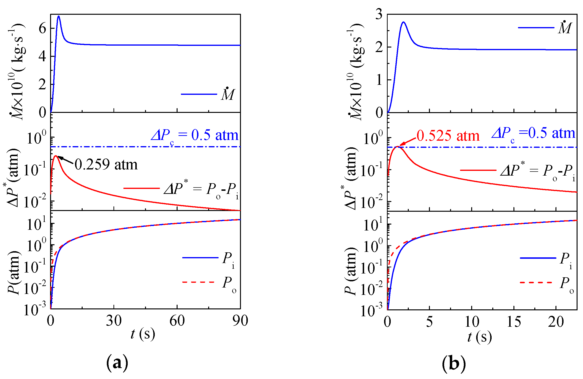
To more clearly understand the effect of pressure variation rate as well as the extreme rupture condition of the hohlraum film, this study investigates the gas flow behaviors of the gas filling and leaking processes in the hohlraum and the maximum of pressure difference between the inside and outside of the ICF hohlraum through varying the pressure variation rate. The gas flow behaviors during the gas filling process are shown in Figure 3. In the initial stage of the gas filling process, the gas mass flow rate quickly rises to its peak value and rapidly decreases to a steady-state value. Furthermore, the pressure difference between the inside and outside of the hohlraum ΔP initially reaches a maximum value ΔPmax, and this is followed by a gradually decrease. This phenomenon indicates that the pressure in the hohlraum and gas filling chamber tends to balance with respect to time. Moreover, an increase in the variation rate of the filling/leaking pressure leads to a larger maximum pressure difference between the inside and outside of the ICF hohlraum during the filling/leaking process ΔPmax.
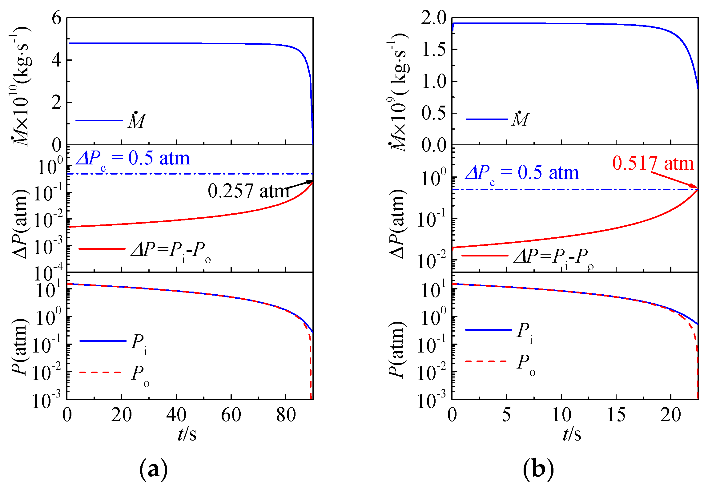
The gas flow behaviors during the gas leaking process are shown in Figure 4. The gas leaking mass flow rate is maintained at a stable value for a long period of time after the leaking process begins, and this is attributed to the extremely low pressure variation rate at this stage. At the end of the leaking process, the mass flow rate decreases abruptly. Furthermore, the pressure difference between the inside and outside of the hohlraum ΔP increases slowly during the initial period of the leaking process and reaches a maximum ΔPmax finally. Additionally, ΔPmax increases when the pressure variation rate of the gas leaking increases.
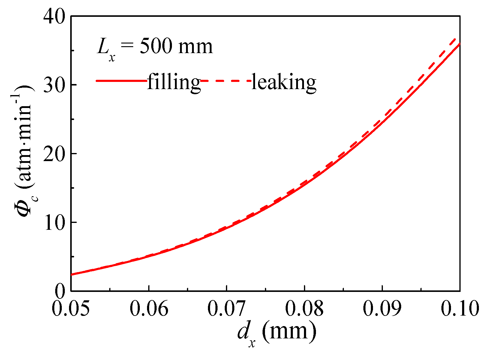
To avoid ICF hohlraum film rupture, it is necessary to analyze the critical rate of pressure variation Φc for the critical pressure value ΔPc. The effect of the pressure variation rate Φ during gas filling and leaking process on the maximum of pressure difference between the inside and outside of the ICF hohlraum ΔPmax is shown in Figure 5. As shown in the figure, under the same physical property and working condition, increases in the rate of pressure variation Φ lead to a larger maximum pressure difference ΔPmax. Additionally, the curves of gas filling and leaking process nearly collapse on each other, and the critical rates of the pressure variation Φc for the gas filling and leaking processes are approximately equal.

3.2. Influence Factor Analysis

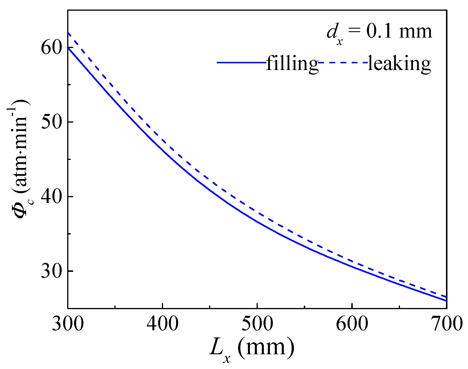
To improve the control capability of gas filling and leaking processes, the influence factors are analyzed in this study. To elucidate the role of the structure parameters of the gas fill tube in the gas flow behaviors during gas filling and leaking processes Figure 6 and Figure 7 compare the critical rate of pressure variation Φc with different structure parameters of the gas fill tube, i.e., diameter dx and length Lx. With the increases in the diameter of the gas fill tube dx and decreases in the length of the gas fill tube Lx, the critical rate of the pressure variation Φc during the gas filling/leaking process gradually increases, thereby leading to a lower probability of the ICF hohlraum film rupture and an increase in the security of the hohlraum.
As mentioned above, the cross-section of the gas fill tube is circular. To examine the effect of the cross-sectional shape of the gas fill tube on the filling/leaking process, a tube with a length of 500 mm and a rectangular cross section is applied to the gas filling and leaking processes. Differing from the equation for the mass flow rate of the tube with circular cross-section, the gas mass flow rate in tube with the rectangular cross-section is calculated as follows [39]:
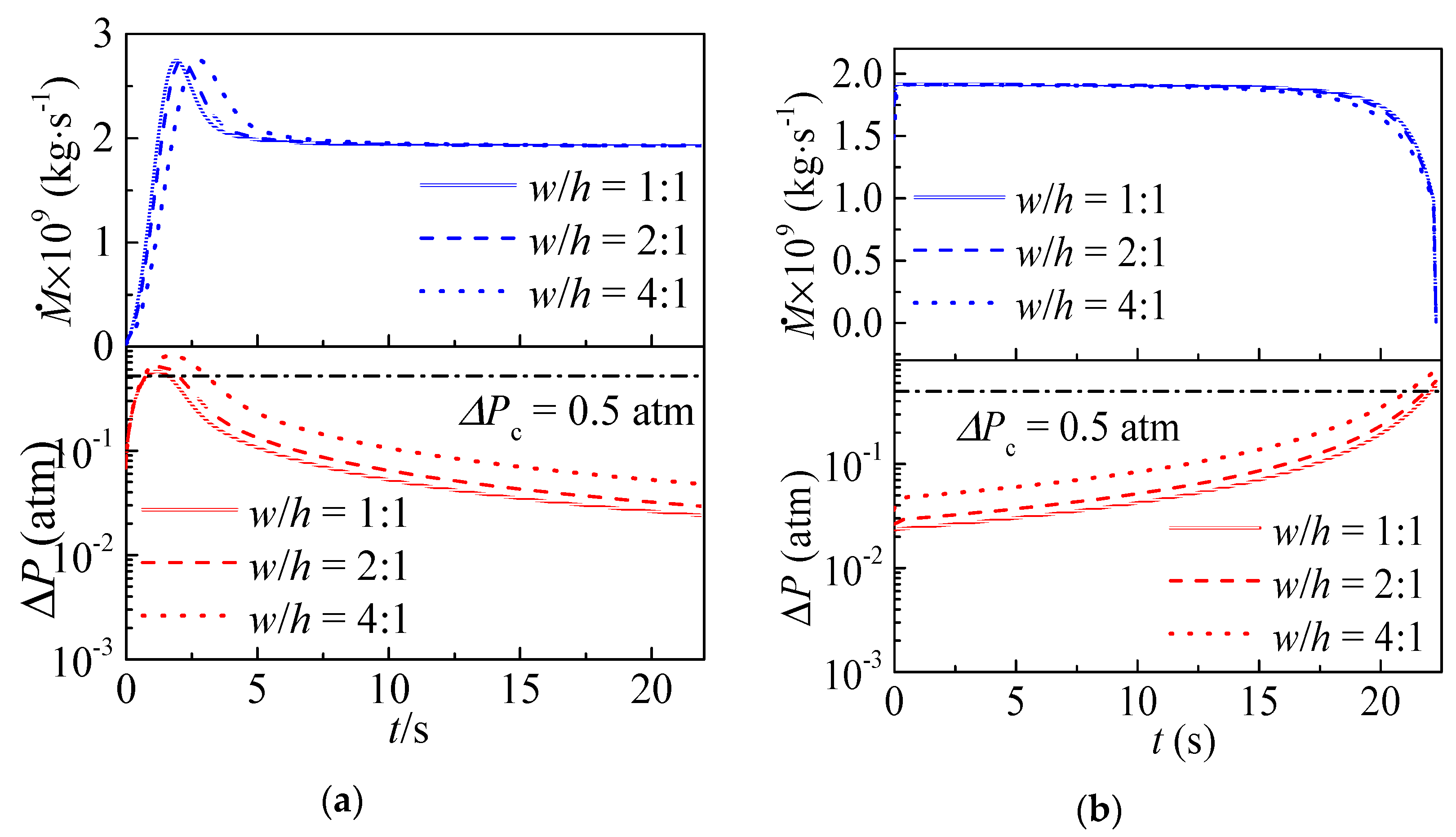
M ˙ = C ( AR ) w h 3 P avg 12 μ 0 R T × Δ P L ( 1 + α K n avg ) ( 1 + 6 K n avg 1 b K n avg )
where w denotes the width of the rectangular cross-section, h denotes the height of the rectangular cross-section, and b = −1. The parameter β = 0.5. C(AR) is a correction coefficient in which the value is related to the aspect ratio of a rectangular section as follows:
C ( AR ) = { 0.42173 , w / h = 1 : 1 0.68605 , w / h = 2 : 1 0.84244 , w / h = 4 : 1
As the aspect ratio of a rectangular section increases, the cross-sectional shape of the gas fill tube departs from a circle to a rectangle. Therefore, the aspect ratio w/h of the gas fill tube with the same rectangular cross section area is varied to understand the effect of cross-sectional shape on the gas flow behaviors during gas filling and leaking processes. Figure 8 shows the time revolution of the gas mass flowrate Φ and the pressure difference between the inside and outside of the hohlraum ΔP. Compared with the gas fill tube with circular cross-section, the pressure difference between the inside and outside of the hohlraum ΔP follows a trend similar to that when the cross-sectional shape of the gas fill tube is rectangular. The maximum pressure difference also occurs at the initial stage of gas filling process or the final stage of gas leaking process. However, increases in the aspect ratio gradually increase the maximum pressure difference ΔPmax, and this is not conducive for the safety of the hohlraum during the gas filling and leaking processes. When compared with the gas filling and leaking processes shown in Figure 3b and Figure 4b with the same pressure rise/drop rate, the maximum pressure difference ΔPmax for the circular cross-section tube is lower than that for the rectangular section tube. Therefore, a departure in cross sectional shape of fill tube from circle to rectangle triggers an increase in pressure difference between the inside and outside of the ICF hohlraum, which raises the risk of polymeric films rupture and decreases the security of the hohlraum structure.
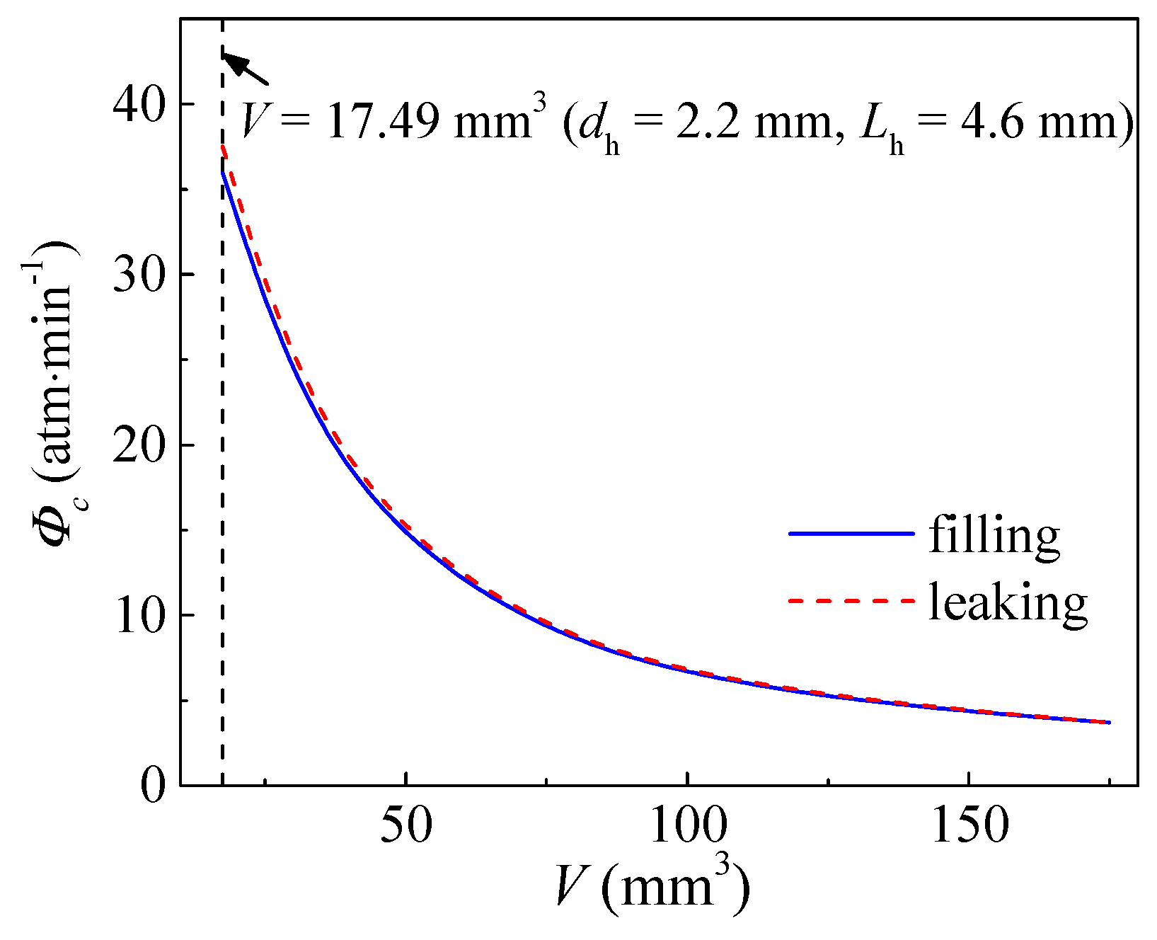
Apart from the structure parameters of the gas fill tube, the size of the hohlraum also significantly affect the gas flow behaviors during gas filling and leaking processes. Figure 9 shows the effect of the hohlraum volume V on the critical rate of the pressure variation Φc during the gas filling and leaking processes. When the hohlraum volume V increases, the critical rate of the pressure variation Φc gradually decreases, thereby resulting in high probability of hohlraum film rupture and a decrease in the security of the hohlraum. Therefore, with respect to the design of the hohlraum, the volume of the target cavity should be reduced to the maximum possible extent based on the premise that the physical requirement is satisfied.
It is well-known that ICF experiments will need to be performed at 10–60 Hz to be of interest for real application of inertial confinement fusion energy. The hohlraums will be filled within an extremely short amount of time before the next one will be filled. In particular, in fact, for the preconceived application of inertial confinement fusion energy, the setting filling pressure of the hohlraum is much less than 15 atm investigated in the current work [29,42]. Therefore, Figure 10 compares the gas fill time of the hohlraum versus the pressure variation during the gas filling processes under different setting filling pressure of the hohlraum. As shown, there is a positive linear relationship between the pressure variation during the gas filling processes and the gas fill time of the hohlraum. That is to say, in order to get a short gas fill time of the hohlraum, we should increase pressure variation rate. If the setting filling pressure is 0.1 atm, which is lower than the critical pressure difference ΔPc = 0.5 atm, the gas fill time of the hohlraum is much smaller than that of 1 atm and 15 atm. In this condition, the gas fill time of the hohlraum may be reduced to 0.1 s as pressure variation rate Φ is 68.2 atm/min.

4. Conclusions

Based on unified flow theory, a theoretical model of the gas flow behaviors during the gas filling and leaking processes of the ICF hohlraum is developed to evaluate and analyze the gas mass flowrate and rate of pressure variation. The role of the fill tube size and the filling pressure on the gas filling and leaking performance are examined and analyzed. The guidelines for safe filling and leaking of the ICF hohlraum are provided. The conclusion are summarized as follows:
  • An increase in the variation rate of the filling/leaking pressure leads to a larger maximum pressure difference between the inside and outside of the ICF hohlraum during the filling/leaking process, and the critical pressure difference of the gas filling process is nearly equal to that of the gas leaking process.
  • Increase in fill tube diameter and decrease in its length both lead to a lower probability of the rupture of polymeric films at two ends of the ICF hohlraum, and thus increases the security of the hohlraum.
  • A departure in cross sectional shape of fill tube from circle to rectangle triggers an increase in pressure difference between the inside and outside of the ICF hohlraum, which raises the risk of polymeric films rupture and decreases the security of the hohlraum structure.
This investigation not only provides a deep understanding of gas filling and leaking processes of the ICF hohlraum with multiscale gas flow problems but also contributes to precisely controlling the gas mass flow rate and pressure variation rate via the optimized fill tube structure and hohlraum volume, which is of significance for the design of the ICF hohlraum with target microgripper. Since the gas flow in ICF hohlraum is a complex multiscale flow problem, the future research work could focus on the hydrodynamics of gas filling and retention via the multiscale three-dimensional unsteady numerical simulation.

Author Contributions

W.Y. provided the guidance and supervision. C.Y. and S.W. implemented the main research, discussed the results, and wrote the paper. All authors read and approved the final manuscript.

Funding

This research was funded by National Natural Science Foundation of China (Nos. 51776037 and 51706194).

Conflicts of Interest

The authors declare no conflict of interest.

References

  1. Nuckolls, J.; Wood, L.; Thiessen, A.; Zimmerman, G. Laser compression of matter to super-high densities: Thermonuclear (CTR) applications. Nature 1972, 239, 139–142. [Google Scholar] [CrossRef]
  2. Lindl, J. Development of the indirect-drive approach to inertial confinement fusion and the target physics basis for ignition and gain. Phys. Plasmas 1995, 2, 3933–4024. [Google Scholar] [CrossRef]
  3. Lan, K.; Liu, J.; Li, Z.; Xie, X.; Huo, W.; Chen, Y.; Ren, G.; Zheng, C.; Yang, D.; Li, S.; et al. Progress in octahedral spherical hohlraum study. Matter Radiat. Extremes 2016, 1, 8–27. [Google Scholar] [CrossRef]
  4. Kirkwood, R.K.; Moody, J.D.; Kline, J.; Dewald, E.; Glenzer, S.; Divol, L.; Michel, P.; Hinkel, D.; Berger, R.; Williams, E.; et al. A review of laser–plasma interaction physics of indirect-drive fusion. Plasma Phys Control. Fusion 2013, 55, 103001. [Google Scholar] [CrossRef]
  5. Itoh, Y.; Fujii-E, Y. Constricted liquid metal curtain for inertial confinement fusion reactors. J. Nucl. Sci. Technol. 1981, 18, 241–248. [Google Scholar] [CrossRef]
  6. Bardi, U. Extracting minerals from seawater: An energy analysis. Sustainability 2010, 2, 980–992. [Google Scholar] [CrossRef]
  7. Gabbar, H.; Stoute, C.A.B.; Bondarenko, D.; Tarsitano, N.; Abdel Rihem, A.; Sirakov, S.; Jani, S.; Menashi, S. X-pinch plasma generation testing for neutron source development and nuclear fusion. Energies 2018, 11, 988–1005. [Google Scholar] [CrossRef]
  8. Wang, J.; Gao, W.; Zhang, H.; Zou, M.; Chen, Y.; Zhao, Y. Programmable wettability on photocontrolled graphene film. Sci. Adv. 2018, 4, 1–6. [Google Scholar] [CrossRef] [PubMed]
  9. Chen, Y.; Liu, X.; Shi, M. Hydrodynamics of double emulsion droplet in shear flow. Appl. Phys. Lett. 2013, 102, 051609. [Google Scholar] [CrossRef]
  10. Chen, Y.; Gao, W.; Zhang, C.; Zhao, Y. Three-dimensional splitting microfluidics. Lab Chip 2016, 16, 1332–1339. [Google Scholar] [CrossRef] [PubMed]
  11. Chen, Y.; Liu, X.; Zhang, C.; Zhao, Y. Enhancing and suppressing effects of an inner droplet on deformation of a double emulsion droplet under shear. Lab Chip 2015, 15, 1255–1261. [Google Scholar] [CrossRef] [PubMed]
  12. Campbell, E.M.; Goncharov, V.N.; Sangster, T.C.; Regan, S.P.; Radha, P.B.; Betti, R.; Myatt, J.F.; Froula, D.H.; Rosenberg, M.J.; Igumenshchev, I.V.; et al. Laser-direct-drive program: Promise, challenge, and path forward. Matter Radiat. Extremes 2017, 2, 37–54. [Google Scholar] [CrossRef]
  13. Murakami, M.; Nishi, D. Optimization of laser illumination configuration for directly driven inertial confinement fusion. Matter Radiat. Extremes 2017, 2, 55–68. [Google Scholar] [CrossRef]
  14. Craxton, R.S.; Anderson, K.S.; Boehly, T.R.; Goncharov, V.N.; Harding, D.R.; Knauer, J.P.; McCrory, R.L.; McKenty, P.W.; Meyerhofer, D.D.; Myatt, J.F.; et al. Direct-drive inertial confinement fusion: A review. Phys. Plasmas 2015, 22, 110501–110654. [Google Scholar] [CrossRef]
  15. Li, F.; Zhang, Z.; Li, J.; Pan, D.; Feng, J.; Shi, R.; Li, B. Study on the strength of titanium doped hollow glass microspheres. J. Non-Cryst. Solids 2017, 459, 18–25. [Google Scholar] [CrossRef]
  16. Wang, T.; Du, K.; He, Z.B.; He, X.S. Development of target fabrication for laser-driven inertial confinement fusion at research center of laser fusion. High Power Laser Sci. Eng. 2017, 5, 1–9. [Google Scholar] [CrossRef]
  17. Kauffman, R.L.; Powers, L.V.; Dixit, S.N.; Glendinning, S.G.; Glenzer, S.H.; Kirkwood, R.K.; Landen, O.L.; MacGowan, B.J.; Moody, J.D.; Orzechowski, T.J.; et al. Improved gas-filled hohlraum performance on nova with beam smoothing. Phys. Plasmas 1998, 5, 1927–1934. [Google Scholar] [CrossRef]
  18. Liu, M.; Zheng, Y.; Li, J.; Chen, S.; Liu, Y.; Li, J.; Li, B.; Zhang, Z. Effects of molecular weight of pva on formation, stability and deformation of compound droplets for icf polymer shells. Nucl. Fusion 2017, 57, 016018. [Google Scholar] [CrossRef]
  19. Vu, H.X.; Wallace, J.M.; Bezzerides, B. An analytical and numerical investigation of ion acoustic waves in a two-ion plasma. Phys. Plasmas 1994, 1, 3542–3556. [Google Scholar] [CrossRef]
  20. Tanaka, K.A.; Yamanaka, T.; Nishihara, K.; Norimatsu, T.; Miyanaga, N.; Shiraga, H.; Nakai, M.; Kitagawa, Y.; Kodama, R.; Kanabe, T.; et al. Cryogenic deuterium target experiments with the gekko xii, green laser system. Phys. Plasmas 1995, 2, 2495–2503. [Google Scholar] [CrossRef] [Green Version]
  21. Williams, E.A.; Berger, R.L.; Drake, R.P.; Rubenchik, A.M.; Bauer, B.S.; Meyerhofer, D.D.; Gaeris, A.C.; Johnston, T.W. The frequency and damping of ion acoustic waves in hydrocarbon (ch) and two-ion-species plasmas. Phys. Plasmas 1995, 2, 129–138. [Google Scholar] [CrossRef]
  22. Fernández, J.C.; Goldman, S.R.; Kline, J.L.; Dodd, E.S.; Gautier, C.; Grim, G.P.; Hegelich, B.M.; Montgomery, D.S.; Lanier, N.E.; Rose, H.; et al. Gas-filled hohlraum experiments at the national ignition facility. Phys. Plasmas 2006, 13, 056319. [Google Scholar] [CrossRef]
  23. Yi, S.; Zhang, Z.; Huang, Q.; Zhang, Z.; Wang, Z.; Wei, L.; Liu, D.; Cao, L.; Gu, Y. Note: Tandem kirkpatrick–baez microscope with sixteen channels for high-resolution laser-plasma diagnostics. Rev. Sci. Instrum. 2018, 89, 036105. [Google Scholar] [CrossRef] [PubMed]
  24. Chen, Y.P.; Deng, Z.L. Hydrodynamics of a droplet passing through a microfluidic t-junction. J. Fluid Mech. 2017, 819, 401–434. [Google Scholar] [CrossRef]
  25. Zhang, C.B.; Chen, Y.P.; Deng, Z.L.; Shi, M.H. Role of rough surface topography on gas slip flow in microchannels. Phys. Rev. E 2012, 86, 016319. [Google Scholar] [CrossRef] [PubMed]
  26. Chen, Y.; Wu, L.; Zhang, C. Emulsion droplet formation in coflowing liquid streams. Phys. Rev. E 2013, 87, 013002. [Google Scholar] [CrossRef] [PubMed]
  27. Zhang, C.B.; Deng, Z.L.; Chen, Y.P. Temperature jump at rough gas-solid interface in couette flow with a rough surface described by cantor fractal. Int. J. Heat Mass Transf. 2014, 70, 322–329. [Google Scholar] [CrossRef]
  28. Deng, Z.; Liu, X.; Zhang, C.; Huang, Y.; Chen, Y. Melting behaviors of pcm in porous metal foam characterized by fractal geometry. Int. J. Heat Mass Transfer 2017, 113, 1031–1042. [Google Scholar] [CrossRef]
  29. Zhang, Z.W.; Li, B.; Tang, Y.J.; Wang, C.Y.; Chen, S.F.; Lin, B.; Chu, X.M.; Huang, Y.H.; Huang, L.Z.; Zhou, L.; et al. Fabrication of the hohlraum gas-filled target connected with gas source. High Power Laser and Part. Beams 2005, 17, 209–212. [Google Scholar]
  30. Zhang, Z.; Huang, Y.; Liu, Y.; Li, B.; Qi, X.; Chen, S. Fabrication of gas-filled targets without gas source. High Power Laser Part. Beams 2009, 21, 79–82. [Google Scholar]
  31. Kline, J.L.; Hager, J.D. Aluminum x-ray mass-ablation rate measurements. Matter Radiat. Extremes 2017, 2, 16–21. [Google Scholar] [CrossRef]
  32. Lindl, J.D.; Amendt, P.; Berger, R.L.; Glendinning, S.G.; Glenzer, S.H.; Haan, S.W.; Kauffman, R.L.; Landen, O.L.; Suter, L.J. The physics basis for ignition using indirect-drive targets on the national ignition facility. Phys. Plasmas 2004, 11, 339–491. [Google Scholar] [CrossRef]
  33. Deng, Z.L.; Chen, Y.P.; Shao, C.X. Gas flow through rough microchannels in the transition flow regime. Phys. Rev. E 2016, 93, 013128. [Google Scholar] [CrossRef] [PubMed]
  34. Chen, Y.P.; Zhang, C.B.; Shi, M.H.; Peterson, G.P. Slip boundary for fluid flow at rough solid surfaces. Appl. Phys. Lett. 2012, 100, 1–4. [Google Scholar] [CrossRef]
  35. Chen, Y.P.; Zhang, C.B.; Shi, M.H.; Wu, J.F. Three-dimensional numerical simulation of heat and fluid flow in noncircular microchannel heat sinks. Int. Commun. Heat Mass Transf. 2009, 36, 917–920. [Google Scholar] [CrossRef]
  36. Wu, J.F.; Shi, M.H.; Chen, Y.P.; Li, X. Visualization study of steam condensation in wide rectangular silicon microchannels. Int. J. Therm. Sci. 2010, 49, 922–930. [Google Scholar] [CrossRef]
  37. Liu, X.; Chen, Y.; Shi, M. Dynamic performance analysis on start-up of closed-loop pulsating heat pipes (CLPHPS). Int. J. Therm. Sci. 2013, 65, 224–233. [Google Scholar] [CrossRef]
  38. Chen, Y.; Zhang, C.; Shi, M.; Yang, Y. Thermal and hydrodynamic characteristics of constructal tree-shaped minichannel heat sink. AIChE J. 2010, 56, 2018–2029. [Google Scholar] [CrossRef]
  39. Karniadakis, G.E.; Beskok, A.; Aluru, N. Microflows and Nanoflows: Fundamentals and Simulation; Springer: New York, NY, USA, 2005. [Google Scholar]
  40. Tison, S.A. Experimental data and theoretical modeling of gas flows through metal capillary leaks. Vacuum 1993, 44, 1171–1175. [Google Scholar] [CrossRef]
  41. Loyalka, S.K.; Hamoodi, S.A. Poiseuille flow of a rarefied gas in a cylindrical tube: Solution of linearized boltzmann equation. Phys. Fluids A 1990, 2, 2061–2065. [Google Scholar] [CrossRef]
  42. Zhang, Z.; Huang, Y.; Liu, Y.; Li, B.; Tang, Y.; Chen, S. Application of polyimide in innertial confinement fusion targets. J. Funct. Mater. 2007, 38, 1678–1682. [Google Scholar]
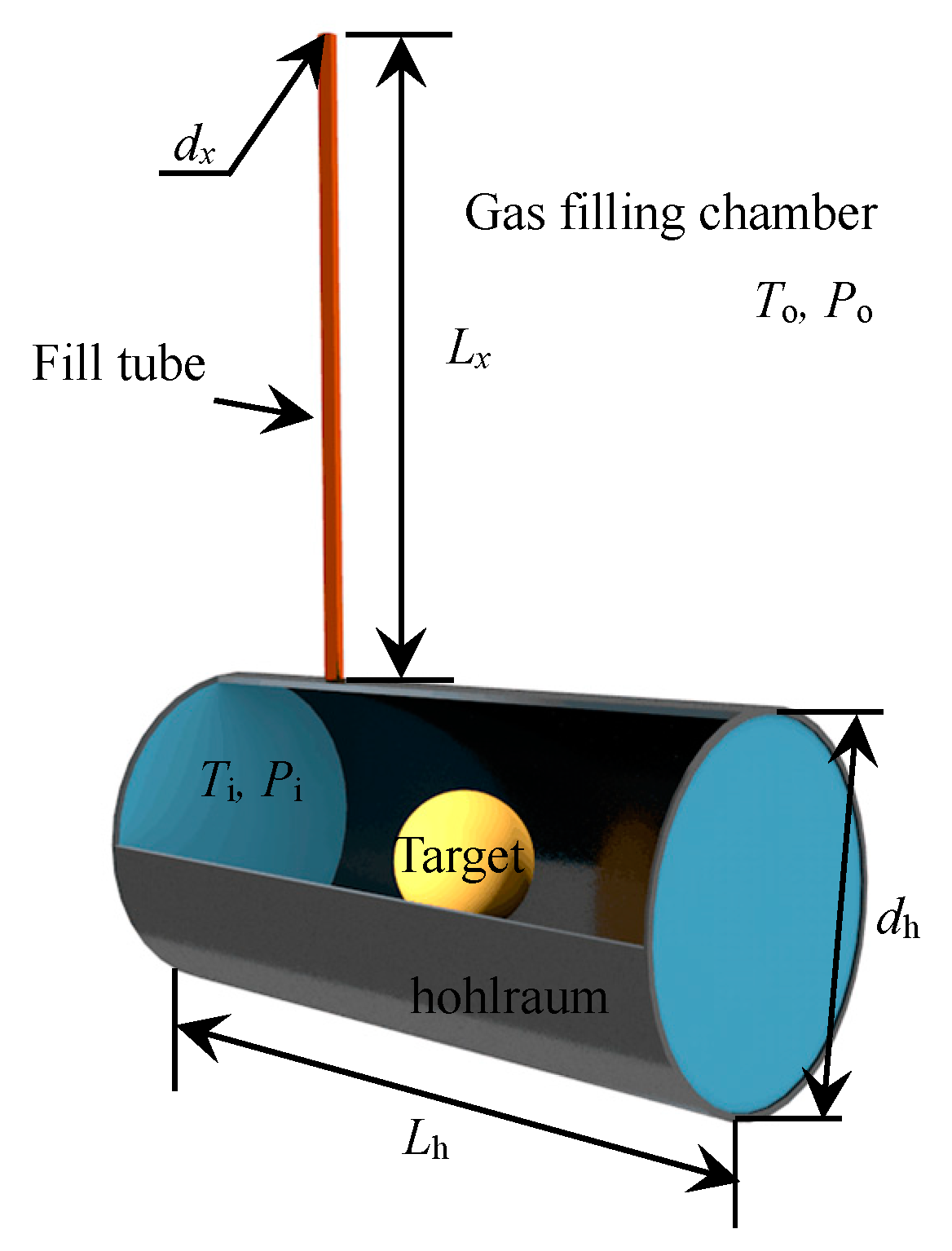
Figure 1. Schematic diagram of the physical model of the gas filling and leaking processes.
Sustainability 10 03763 g001
Figure 2. Effect of the Knudsen number on the gas mass flow rate: comparison between the analytical solution of the Boltzmann equation [41] and numerical simulation based on the unified flow model.
Sustainability 10 03763 g002
Figure 3. Gas flow behaviors during the gas filling process: (a) the pressure rise rate is 10 atm/min; (b) the pressure rise rate is 40 atm/min.
Sustainability 10 03763 g003
Figure 4. Gas flow behaviors during the gas leaking process (pressure decreases from 15 atm to 0.001 atm): (a) the pressure drop rate is 10 atm/min; (b) the pressure drop rate is 40 atm/min.
Sustainability 10 03763 g004
Figure 5. Effect of the critical rate of pressure variation during the gas filling and leaking processes on the maximum pressure difference between the inside and outside of the ICF hohlraum.
Sustainability 10 03763 g005
Figure 6. Effect of the diameter of the gas tube on the critical rate of pressure variation during the gas filling and leaking processes.
Sustainability 10 03763 g006
Figure 7. Effect of the length of the gas tube on the critical rate of pressure variation during the gas filling and leaking processes.
Sustainability 10 03763 g007
Figure 8. Effect of the rectangular tube aspect ratio on (a) the gas filling and (b) the gas leaking processes (both the pressure rise rate and drop rate of gas filling chamber are 40 atm/min).
Sustainability 10 03763 g008
Figure 9. Effect of the hohlraum volume on the critical rate of pressure variation during the gas filling and leaking processes.
Sustainability 10 03763 g009
Figure 10. Effect of the pressure variation during the gas filling processes on the gas fill time of the hohlraum.
Sustainability 10 03763 g010