Technical Note

Mode 2 Charging—Testing and Certification for International Market Access

VDE Pruef- und Zertifizierungsinstitut GmbH, Merianstrasse 28, D-63069 Offenbach, Germany
World Electr. Veh. J. 2018, 9(2), 26; https://doi.org/10.3390/wevj9020026
Submission received: 8 May 2018 / Revised: 25 June 2018 / Accepted: 18 July 2018 / Published: 20 July 2018

Abstract

:
This paper provides an analysis of the current IEC 62752 standard. Establishing measures to protect against electric shock is one of the major tasks in the development of safe electric appliances. For electric vehicles this is very important too, because they are movable and in a public area most of the time. Even during recharge of the batteries, it is very likely that the electric vehicle is accessible to playing children or other people. IEC 62752 is a standard for a product which connects the electric vehicle with a standard household socket. This connection is required to provide electricity to the on-board charger of the electric vehicle and is called Mode 2 charging. In this article, the complexity of worldwide standardization for eMobility products is shown. Because the development of these products is still going on, some special requirements of IEC 62752 are explained, and some unique tests are described to help development engineers to design a safe, reliable, and durable product.

Graphical Abstract

1. International Standardization and Regulation

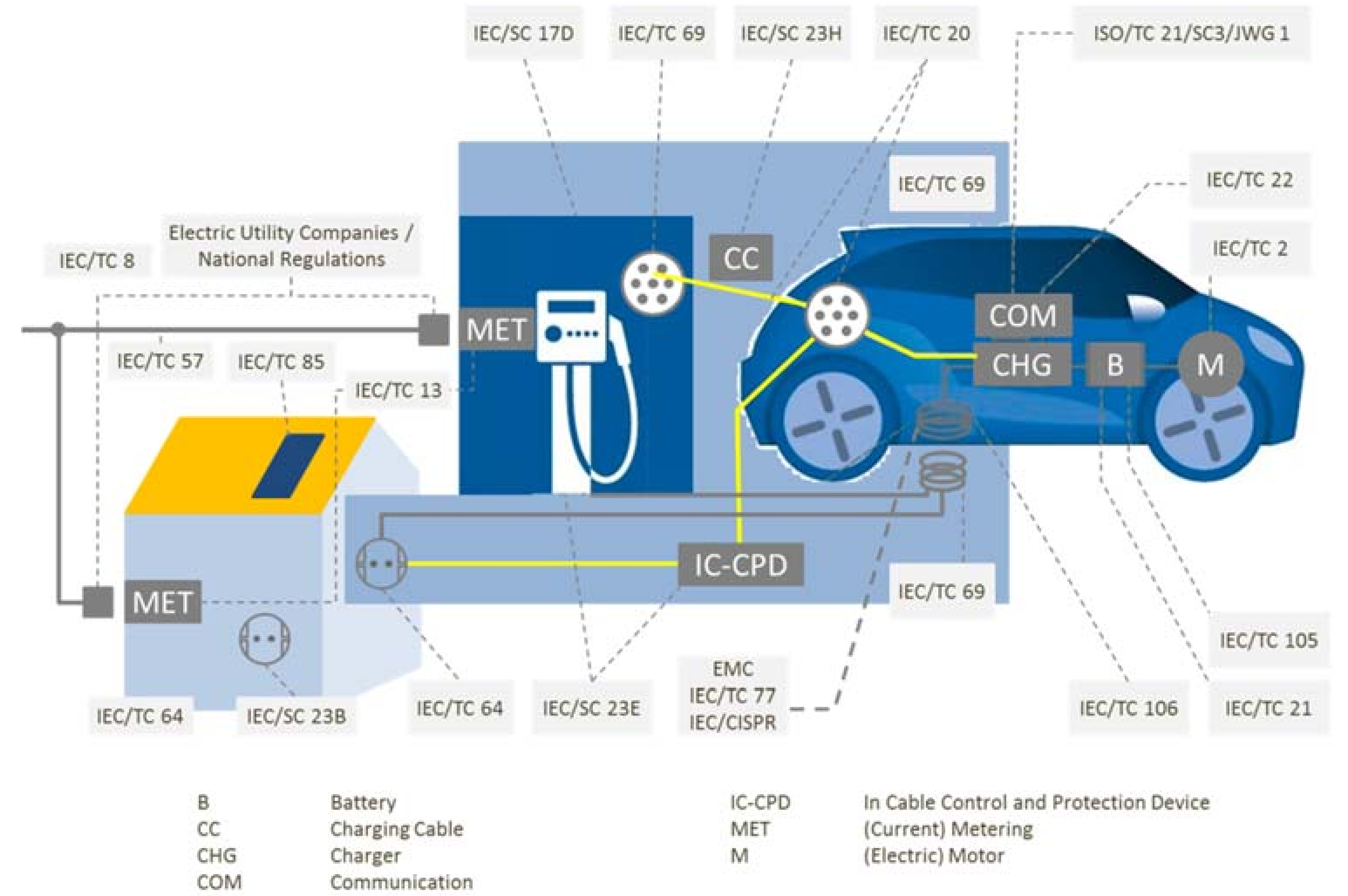
1.1. Standardization Groups and Trading Zones

For historical reasons, national standardization has been established to achieve interoperability and to ensure a minimum safety standard to reduce risk while using applicable products. Because of the global nature of business activities, harmonization of standards has started. This is an ongoing process. For electrotechnical issues, the IEC—“International Electrotechnical Commission”—is the leading organization for international standardization.
Because the eMobility market is a relatively new market, there is a great deal of standardization occurring. Figure 1 provides a rough overview of different working groups within the standardization groups IEC (International Electrotechnical Commission) and ISO (International Organization for Standardization). The responsibility of the different standardization organizations is shown in Table 1.
These international standards have to be transferred to national standards and regulations. Table 1 gives a rough overview about international standardization and its relationship to regulation.
International standards will normally be transferred to the different trading zones. Within the trading zones, these (adopted) standards are transferred to national (adopted) standards. The legislative authorities normally use the corresponding standards as a basis for regulations. So even having a “worldwide” standard for technical or political reasons, there are still national or local specialties. Therefore, to achieve international market access, a lot of work has to be done.
Figure 2 gives a rough overview of the complexity of the worldwide market access.
Some countries require separate testing at local laboratories, and some accept tests done, for instance, according to the CB Scheme of IECEE. This is a system for mutual recognition of test certificates for electrotechnical equipment and components [1]. The VDE Certification and Testing Institute is able to test and certify according to the required certification for our customers to achieve access to the local market.

1.2. Current Activities in Standardization

The eMobility market has seen many improvements in products. New technical improvements have to be considered to ensure interoperability and safe operation. Therefore, existing standards go into maintenance status more or less when almost published.
The following examples of ongoing and “new” standardization give an overview of the existing market and future trends within eMobility (see also Figure 1):
  • Improving the IEC 62752 standard to implement actual development.
  • Standardization for pluggable/portable Electric Vehicle Supply Equipment (EVSE) will be implemented in the Amendment of IEC 62752:2016. An Amendment will be published next year.
  • IEC 61851-1:2017 has become a system standard for charging electric and hybrid electric vehicles.
  • The standard for Residual Direct Current Detecting Devices (RDC-DD) IEC 62955:2017 is on revision at the European Committee for Electrotechnical Standardization (CENELEC).
  • Charging cables are specified in IEC 62893-1:2017, IEC 62893-2:2017, and IEC 62892-3:2017.
  • Requirements for Electromagnetic compatibility (EMC) with respect to charging of electric and hybrid electric vehicles have been published in IEC 61851-21-1:2017 for “on-board charger” and IEC 61851-21-2:2018 for “off-board charger”.
  • Standardization for high-power DC charging, as an extension of IEC 61851-23, is in CD state. The scope has been extended to 1500 V DC charging voltage. Within the 2nd CD a maximum nominal current of 400 A is specified. But this value is in discussion.
  • Standardization for bi-directional charging (load leveling) has been started and will be implemented in IEC 61851-23.
  • IEC 61851-24 is in maintenance status and will include so-called high-power charging with cooling.
  • Extension of IEC 62196-1 for high-power charging is in CD state.
  • New IEC 62196-3-1 for so-called high-power charging with cooling is also in CD state.
  • Standardization for wireless charging is ongoing (IEC 61980-1:2015).
  • Standardization for e-Bikes, e-Scooters, and even trucks and buses has started.
  • etc.
Even eMobility is starting to become a real mass market which has to ensure interoperability, reliability, and safety. Because it is a new market, the public is very sensitive to injuries.
Sometimes standards for certain products are not available or finished. Therefore, a partner being familiar with electric safety, risk assessments, functional safety, interoperability, etc. can be very helpful during design and validation. Furthermore, it is mandatory to do a risk assessment and implement the results in the design and validation stages. Because of its fundamental knowledge about the application, VDE is able to help the manufacturer.

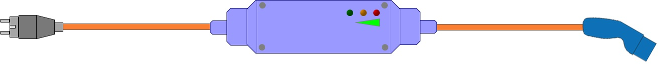
2. Mode 2 Charging Equipment

Here, the IC-CPD (in-cable control and protection device) is used as an example to illustrate the interaction and subjects of different standardization groups (Figure 1).

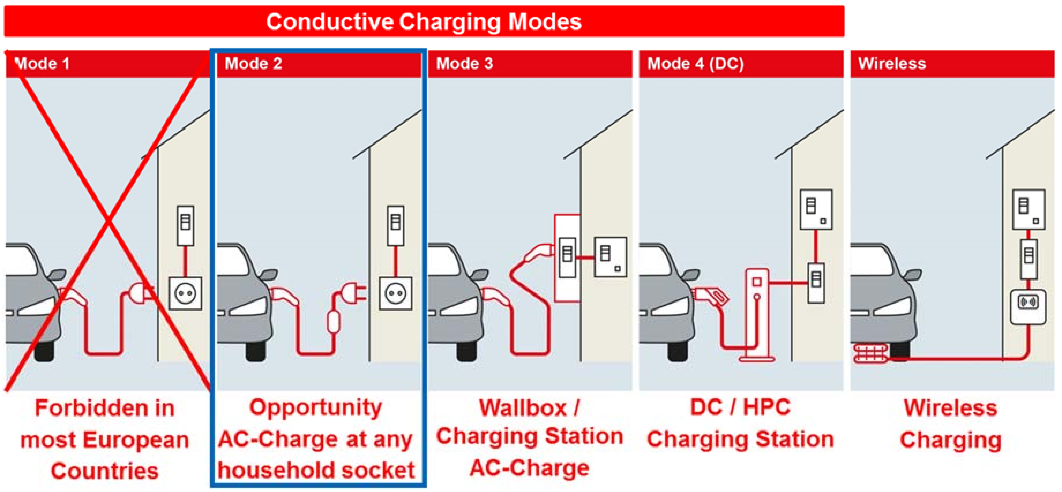
2.1. Overview of Different Charging Modes

Before starting a description of Mode 2 charging, a short overview about the actual global situation shall be given.
Similar to the different household connecting systems all over the world, there are different types of connection systems for electric and hybrid vehicles. In case the charger for the battery is in the vehicle, alternating current (AC) is transferred from the supply to the vehicle. If the charger is outside the vehicle (at a certain location) direct current (DC) is transferred to the vehicle in order the charge the battery directly.
  • Type 1 connection is based on the standard SAE J1772. SAE International is a standardization organization in the United States of America.
  • Type 2 connection will be the standard AC connection within Europe
  • Type 3 connection is a special AC connecting system using shutters
  • AA describes a connection according to CHAdeMO specification
  • BB connection is used in China
  • EE connection is a combination of DC and Type 1 (SAE J1772) connections
  • FF connection is a combination of DC and Type 2 connections
Figure 3 shows different charging modes. Table 2 states a description of different charging modes and their major electrical parameters.

2.2. Technical Issues: Why to Use Mode 2 Charging

Electric power supply in normal household is not always according to actual standards or regulations because of preservation of the status quo. The electric vehicle has a large touchable surface, and it may be connected to electric power supply for a long time outside and open to the public. Therefore, specialists all over the world decided to establish a so-called Mode 2 charging to reduce the risk of electric shock.
For the following a TN supply system according to IEC 60364-1 Clause 312.2.1 [6] will be considered. It is used as an example to understand why there are requirements like residual current device (RCD) function and upstream protective conductor identification.
Different failures within the electric supply in houses have been found even in well-developed countries like Germany [7].
  • Example 1 of Figure 4: Within households, installation of a broken phase (L) or neutral (N) line can happen because of a loose connection over time. This fault is obvious, because the electric equipment does not work. So, an electrician can be ordered to fix it.
  • Example 2 of Figure 4: A broken protective ground (PE) line is not obvious, but a concealed defect. Because this is not an obvious fault, it can be there for a long time before being recognized. The reason for this can also be a loose connection over time. If a ground fault occurs in cable-connected Class I equipment, an electric shock can happen. This is the reason for installing RCDs in the house. As mentioned before, this is not always available in older houses. This example illustrates why there is the demand for the detection of an “open protective conductor” within IEC 62752.
  • Example 3 of Figure 4: In older houses, PEN lines might be installed. If there is an open PEN line, the cable-connected equipment does not work, like in Example 1. This obvious fault can be repaired by an electrician.
  • Examples 4 and 5 of Figure 4: If somebody did a job incorrectly, phase (L) and protective ground (PE) or PEN may have been connected incorrectly, as indicated. If Class II appliances are used, they do not work, and because of the nature of Class II, there is no danger. However, if Class I appliances are connected to this socket, the enclosure of the appliance is connected to phase (L). In this case, even an RCD is of no value, because there is no difference in current flow between PE and N or PEN and L.
  • These examples show the need for a product with a “switched protective conductor”. A life protective conductor can be switched off and, therefore, no line voltage is on the vehicle chassis any longer.
These examples show how important the knowledge about the supply is to develop a standard for IC-CPDs.
Because of these known faults, some countries do not allow Mode 1 charging. The above-described and other possible failures are the reason that Mode 2 charging for conductive low-power charging has been established.
Furthermore, some countries limit the charging current in a household. Even for a 16A electric power supply, 10A or 8A are allowed only to reduce the hazard of fire in the electric power supply in older houses. Therefore, despite the established standards, these limitations have to be considered. This can be done by implementing the correct duty factor of the control pilot signal.

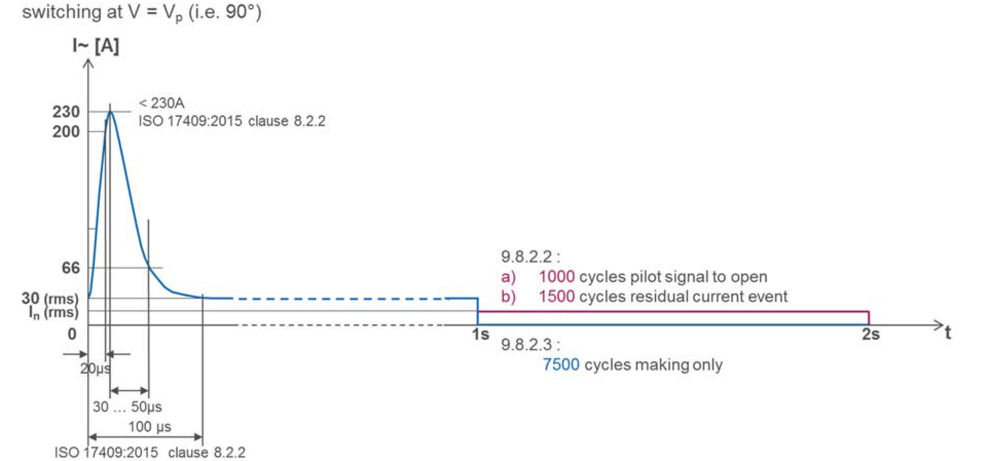
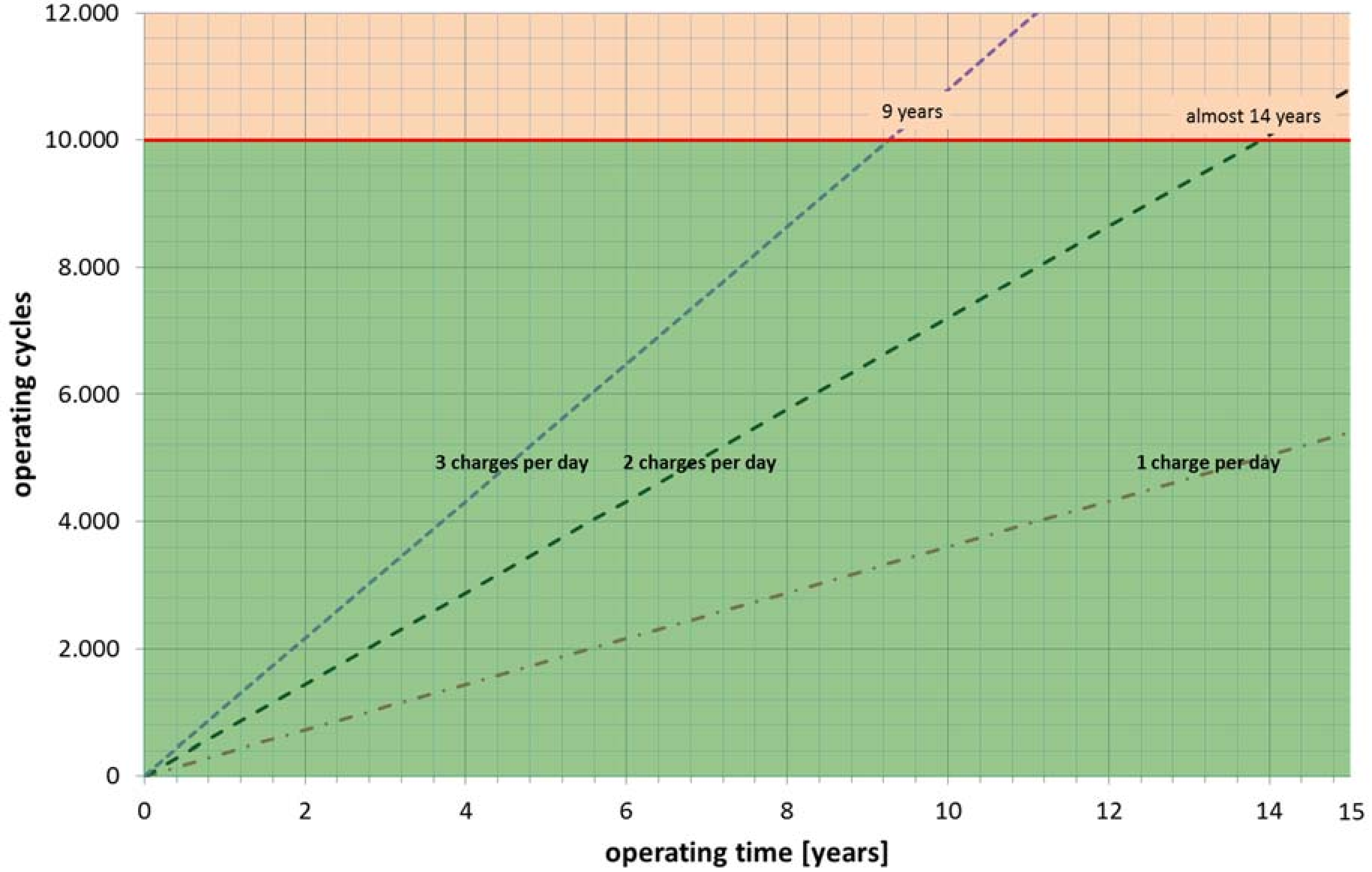
2.3. Contactor Requirements

Protection against electric shock can be achieved by disconnecting the electrical device from the supply. Therefore, contactors are very important. Measurements in electric vehicles have shown a very special inrush current pulse (ISO 17409). This has to be considered for the design. So, requirements on the contactors are now not only because of the supply, but also because of the electric vehicle.
Some contactors show different service lives when used in different orientations (see Figure 5). Therefore, for the design of the function box, it has to be considered that the endurance of a contactor may depend on how it is implemented in the function box of the IC-CPD.
The endurance test of the IC-CPD is much different from other applications. Figure 6 illustrates the test procedure according to IEC 62752 stating the corresponding clauses. In total, 10000 duty cycles have to be passed.
  • 7500 duty cycles are done by closing the contacts at inrush current (the pulse within Figure 6) and opening the contact without any electric current flowing (blue line within Figure 5, see IEC 62752 clause 9.8.2.3).
  • 2500 duty cycles are done by closing contacts at inrush current (the pulse within Figure 6) and opening the contacts at rated current (red line within Figure 5, see IEC 62752 clause 9.8.2.2 (a) and (b)).
How the product is used has a large impact on the service life of the IC-CPD (Figure 7). As stated above, the contactors of the IC-CPD have to pass 10,000 duty cycles. If the IC-CPD is used three times daily (i.e., twice during daytime and one overnight recharge), it takes roughly 9 years to do 10,000 duty cycles. If the IC-CPD is used for overnight charging and one more time during the day (twice a day) it takes almost 14 years to get 10,000 duty cycles. If it is used only once a day, it takes more than 15 years. So, the specified number of duty cycles is to ensure the service life of the IC-CPD is more or less the same than the expected vehicle (battery) life.

2.4. DC Residual Current Protection

Direct residual current (DC) protection is in place due to the possible operating conditions of the electric vehicles. During operation of high-frequency chargers, it is possible that DC residual currents (pulsed or smooth) will occur. If this happens, it is possible to “blind” the RCD Type C in the electric power supply of the house. Therefore, it is recommended to use RCD Type B for Mode 3 and Mode 4 charging. For Mode 1, it is forbidden to use a charger producing a DC residual current of more than 6 mA. For Mode 2, there has to be a protection against this. In other words, switch off the power if a DC residual current exceeds 6 mA! Since 1 January 2018, it is no longer allowed to sell IC-CPDs without this feature. This period was provided to provide a chance to develop such a protection device. Otherwise, ISO 17409 [8] would have to include the requirement that DC residual currents (pulsed or smooth) are prohibited.

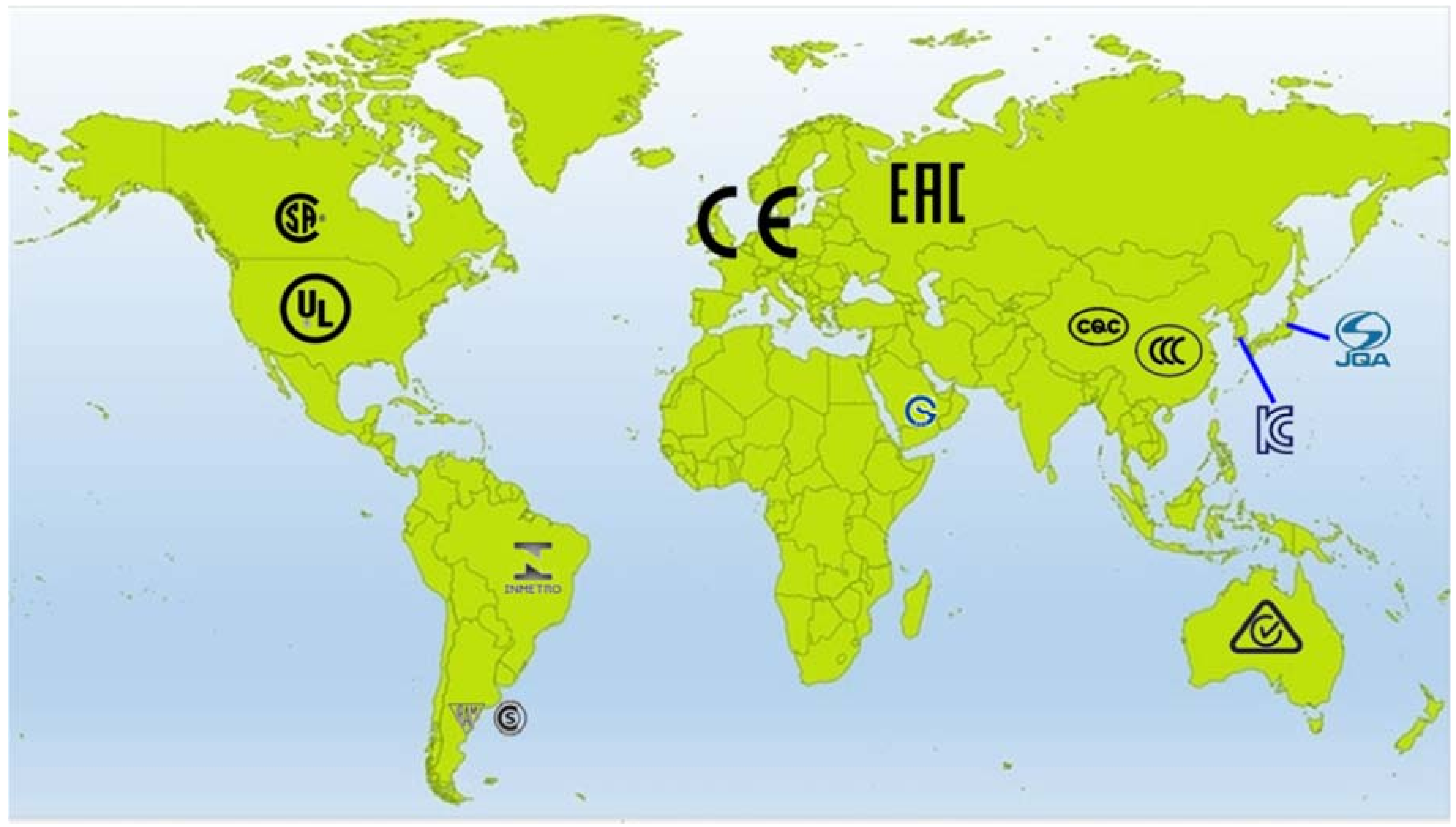
2.5. National Requirements

The reasons for clause 2.2 requirements with respect to the supply have been explained, and the special requirements in clause 2.3 for electric vehicles have been discussed. The discussion will be concluded by mentioning additional country regulations.
Besides the technical requirements stated within IEC 62752, there are sometimes additional national requirements for IC-CPDs. There are countries which require, e.g., a suspension system to prevent excessive forces from the function box to the wall socket outlet. In some countries, the cable length between the plug and function box is limited to 30 cm.
The following countries have national requirements not based on IEC standards:
  • USA;
  • Canada;
  • Mexico;
  • Japan; and
  • China.
These national requirements have to be fulfilled to get market access. This information and more are part of our international certification service. So, the customer receives testing and certification activities, allowing worldwide market access, from VDE.

3. Conclusions

eMobility has become a real market. Users and country authorities have become sensitive to electric safety. Because of a growing market, accidents become more likely. The manufacturer has product responsibility. Therefore, it is mandatory to develop and produce products at least according to international standards, as well as to regional requirements.

Funding

This research received no external funding.

Conflicts of Interest

The author declares no conflicts of interest.

References

  1. IEC System of Conformity Assessment Schemes for Electrotechnical Equipment and Components (IECEE). IECEE and CB Scheme; International Electrotechnical Commission: Geneva, Switzerland, 2016; Available online: https://www.iecee.org/documents/presentations/ppt/iecee-and-cb-scheme_2016-08.pptx (accessed on 20 July 2018).
  2. International Electrotechnical Commission. IEC 61851-1:2017-02 “Electric Vehicle Conductive Charging System—Part 1: General Requirements”; International Electrotechnical Commission: Geneva, Switzerland, 2017. [Google Scholar]
  3. International Electrotechnical Commission. IEC 62196-1:2014-6 “Plugs, Socket-Outlets, Vehicle Connectors and Vehicle Inlets—Conductive Charging of Electric Vehicles—Part 1: General Requirements”; International Electrotechnical Commission: Geneva, Switzerland, 2014. [Google Scholar]
  4. International Electrotechnical Commission. IEC 62196-2:2016-02 “Plugs, Socket-Outlets, Vehicle Connectors and Vehicle Inlets—Conductive Charging of Electric Vehicles—Part 2: Dimensional Compatibility and Interchangeability Requirements for a.c. Pin and Contact-Tube Accessories”; International Electrotechnical Commission: Geneva, Switzerland, 2016. [Google Scholar]
  5. International Electrotechnical Commission. IEC 62752:2016-03 “In-Cable Control and Protection Device for Mode 2 Charging of Electric Road Vehicles (IC-CPD)”; International Electrotechnical Commission: Geneva, Switzerland, 2016. [Google Scholar]
  6. International Electrotechnical Commission. IEC 60364-1:2005-11 “Low-Voltage Electrical Installations—Part 1: Fundamental Principles, Assessment of General Characteristics, Definitions”; International Electrotechnical Commission: Geneva, Switzerland, 2005. [Google Scholar]
  7. Elektro-Beratung Bayern, Landwirtschaftlicher Prüfdienst (EBB). Statistik der Prüfung der elektrischen Anlagen und Energieverbrauchsgeräte von Landwirtschaftlichen Betrieben in Bayern im Jahr 2008—Gesamtübersicht; Elektro-Beratung Bayern, Landwirtschaftlicher Prüfdienst: Munich, Germany, 2009. [Google Scholar]
  8. International Organization for Standardization. ISO 17409:2015-11 “Electrically Propelled Road Vehicles—Connection to an External Electric Power Supply—Safety Requirements”; International Organization for Standardization: Geneva, Switzerland, 2015. [Google Scholar]
Figure 1. Different working groups within IEC and ISO to establish or adopt existing standards for eMobility to ensure interoperability and safe use of different products.
Wevj 09 00026 g001
Figure 2. Rough overview of different certifications for market access.
Wevj 09 00026 g002
Figure 3. Illustration of different charging modes. Mode 2 is discussed in this paper.
Wevj 09 00026 g003
Figure 4. Possible failures within (private) power supply and possible risks using Class I appliances (like electric vehicles). As can be seen from Figure 4, different failures in electric power supply can result in different risks.
Wevj 09 00026 g004
Figure 5. Orientations of contactors.
Wevj 09 00026 g005
Figure 6. Endurance test pulses for in-cable control and protection device (IC-CPD) according to IEC 62752.
Wevj 09 00026 g006
Figure 7. Calendric life for different use cases.
Wevj 09 00026 g007
Table 1. Example for international standardization and the relationship to regulations.
Standardization Regulation
GeneralElectro-Technics /ElectronicsTelecommunication
International StandardizationWevj 09 00026 i001Wevj 09 00026 i002Wevj 09 00026 i003Wevj 09 00026 i004
European StandardizationWevj 09 00026 i005Wevj 09 00026 i006Wevj 09 00026 i007Wevj 09 00026 i008
National Standardization
(example Germany)
Wevj 09 00026 i009Wevj 09 00026 i010Wevj 09 00026 i011National Regulation
Table 2. Description of different charging modes and their major parameters [2,3,4,5].
Charging ModeDescriptionMaximum Current and Voltage
Mode 1conductive connection between a standard socket-outlet of an AC supply network and electric vehicle (EV) without communication or additional safety features16 A and 250 V AC, 1-phase
16 A and 480 V AC, 3-phase
Mode 2conductive connection between a standard socket-outlet of an AC supply network and electric vehicle with communication and additional safety features32 A and 250 V AC, 1-phase
32 A and 480 V AC, 3-phase
Mode 3conductive connection of an EV to an AC EV supply equipment permanently connected to an AC supply network with communication and additional safety features1: 32A and 250 V AC, 1-phase
2: 70 A and 250 V AC, 1-phase
63 A and 480 V AC, 3-phase
3: 16/32 A and 250 A AC,
1-phase 63 A and 480 V AC, 3-phase
Mode 4conductive connection of an EV to an AC or DC supply network utilizing a DC EV supply equipment, with (high-level) communication and additional safety featuresAA: 200 A and 600 V DC
BB: 250 A and 600 V DC
EE: 200 A and 600 V DC
FF: 200 A and 1000 V DC

